

Page 1

Application Report
SLLU043B – JANUARY 2006
TUSB3410UARTPDK User’s Guide
Connectivity Solutions
Contents
Overview..........................................................................................................................................2
1
1.1 What’s Included.........................................................................................................................2
1.2 Hardware/Software Requirements for TUSB3410UARTPDK ...................................................2
1.3 TUSB3410UART EVM Board Overview....................................................................................3
2 System Setup and Procedure ........................................................................................................3
2.1 A Note on PIDs for TUSB3410UART EVM...............................................................................6
3 EVM Materials..................................................................................................................................9
3.1 BOM .......................................................................................................................................9
3.2 Layout .....................................................................................................................................10
3.3 Schematic................................................................................................................................10
Figures
Figure 1.
Figure 2. Typical System Setup........................................................................................................4
Figure 3. Enumeration on Windows 98............................................................................................5
Figure 4. Enumeration on Windows 2000/XP ..................................................................................6
TUSB3410UART Evaluation Module.................................................................................3
1
Page 2

SLLU043B
1 Overview
The TUSB3410UARTPDK is a product design kit (PDK) intended to showcase the TUSB3410
as a compact USB to serial interface bridge. Together with TI’s Virtual COM Port (VCP)
software, it produces a turnkey, configurable USB/serial bridge solution.
TI provides all components necessary to complete the solution:
• the integrated circuit devices
• firmware to run on the device
• drivers (Windows, Mac OS, Linux)
• utilities and instructions necessary for the designer to implement the solution in the end
design.
The information in this kit is subject to change, and software updates are ongoing. For the latest
information pertaining to this kit, please visit http://www.ti.com/rd/tusb3410uart
version of the software, please visit www.ti.com/rd/tusbwinvcp
1.1 What’s Included
. For the latest
.
This kit contains the following:
• “Getting Started” document (SLLU048B)
• TUSB3410UART EVM
• USB cable (certified by the USB-IF)
• Serial cable
• An application note, “Application of TI’s VCP Software Solution” (SLLA170) which walks the
designer through the process of implementing the VCP solution.
The driver/firmware software package must be downloaded from TI’s website (www.ti.com). TI
distributes this software via the web so that you are sure to get the latest build. Please see the
“Getting Started” document for specific instructions in obtaining the software.
1.2 Hardware/Software Requirements for the TUSB3410UARTPDK
The TUSB3410UART EVM is designed for use with a personal computer running a USB–
enabled operating system. The PC should be compliant with the USB 1.1 or 2.0 specifications.
This implies that the BIOS, chipsets, and operating system are all USB specification compliant.
The TUSB3410UARTPDK is primarily intended for evaluation with the Windows version of the
VCP driver. All descriptions provided in this user’s guide assume that Windows is the software
environment. While the Linux and Mac OS versions could be used as well, they may require
additional configuration. Contact TI if you’re interested in these alternate versions of the driver.
2 TUSB3410UARTPDK User’s Guide
Page 3
SLLU043B
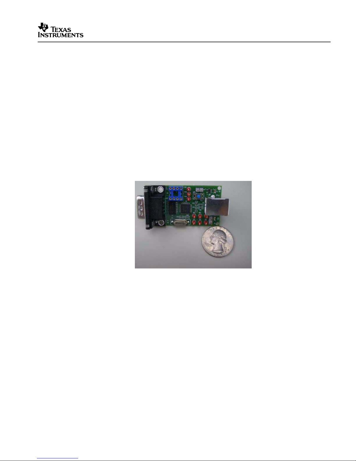
1.3 TUSB3410UART EVM Board Overview
The TUSB3410UART evaluation module (EVM) provided in this kit is specifically designed to
showcase the TUSB3410 as a compact USB to serial interface bridge. TUSB3410 interfaces
full-speed (12Mbps) USB to a high-speed UART. The EVM adds an RS232 driver to interface to
standard serial port devices.
Included in the TUSB3410 EVM design are an I2C serial EEPROM, a 12MHz crystal, and a 5Vto-.3V low-dropout voltage regulator. The EEPROM contains code to boot the TUSB3410’s
internal 8052 micro controller and other configuration parameters while the 12MHz crystal
provides the clock source for the device. The 5V-to-3.3V voltage regulator converts the 5V USB
bus power to 3.3V, which is required by the TUSB3410.
The EVM operates from 5V USB bus power. A TUSB3410 solution may be either self-powered
or bus powered.
The EVM is 3cm by 6cm. See Fig. 1.
Figure 1. TUSB3410UART Evaluation Module
2 System Setup and Procedure
Download the software per the instructions in the “Getting Started” document accompanying this
kit. Install the driver according to the instructions.
Please run the installer included in the driver package rather than allowing Windows to conduct
the installation. While it is possible to do a proper install by first attaching the EVM and allowing
Windows to complete the installation, running the installer is more automated. The installer
seeks out and resolves any conflicts that could prevent the driver from working properly.
Be sure to run the appropriate version of the installer depending on your version of Windows
(Windows 98/ME or Windows 2000/XP). The installer places both the driver and a firmware file
that will be downloaded to the EVM when it is attached.
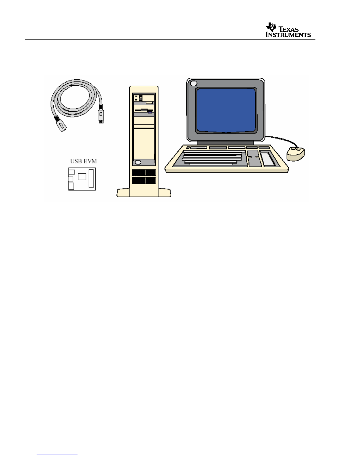
Fig. 2 shows the typical system setup.
TUSB3410UARTPDK User’s Guide 3
Page 4
SLLU043B
Figure 2. Typical System Setup
Attach a serial device to the TUSB3410UART EVM using the serial cable and attach the EVM to
the PC using the USB cable. The first time you attach the EVM to the host PC, Windows
displays “bubble” information in the lower right corner, showing text that originates in the
EEPROM device located on the board. This is information you can customize for your product.
Also located in the EEPROM is a device descriptor containing a Vendor ID (VID) and Product ID
(PID). For the TUSB3410UART EVM, these values are 0x0451 (the VID assigned to TI by the
USB Implementers Forum) and 0x341A (the PID TI has assigned to this EVM), respectively.
The operating system uses the VID/PID combination to identify the type of device that has been
attached, and therefore what driver it needs to load. The VCP driver is configured to respond to
the 0451/341A VID/PID pair.
Furthermore, the EEPROM includes a string descriptor containing a serial number for this EVM.
The operating system uses the combination of the VID, PID, and serial number to distinguish
this particular EVM from other instances off this EVM. For example, COM port settings will be
associated with that particular combination of VID, PID, and serial number. Windows presents
the “Found New Hardware” dialog whenever it sees a new combination of these three values.
If the VCP installer setup was run before attaching the EVM, the installation will occur
automatically. If the installer was not run first, guide Windows to the correct INF files within the
installer directory.
4 TUSB3410UARTPDK User’s Guide
Page 5

SLLU043B
Note that Windows may state that the driver is not certified by Microsoft. TI has verified that the
driver passes Microsoft’s HCT test setup, but to date has not submitted the driver for
certification. Any certification TI acquires will have to be performed again by target companies
prior to their specific product release due to regulations by Microsoft and the USB IF.
Nevertheless, TI is pursuing certification in the first quarter of 2005.
Because the VCP driver architecture contains two modules, one for the USB functionality and
one for the COM port functionality, Windows will present the “Found New Hardware” dialog
twice. For the same reason, you should be able to see the solution enumerate in two places in
the Windows Device Manager when installation is complete. For the Windows 9x driver, it
enumerates as a “VCP device” and also as a new COM port, as shown in Fig. 3.
Figure 3. Enumeration on Windows 98
For the Windows 2000/XP driver, it enumerates as a “multiport serial adapter”, and also as a
new COM port, as shown in Fig. 4.
TUSB3410UARTPDK User’s Guide 5
Page 6

SLLU043B
Figure 4. Enumeration on Windows 2000/XP
The serial device should now be accessible.
2.1 A Note on PIDs for TUSB3410UART EVM
Prior to March 2005, the EVM shipped without an EEPROM device in socket U5. As a result,
the TUSB3410 reported its default VID, PID, and serial number to the host, and the INF files for
the VCP driver were configured to associate with these values. TI provides another driver
(AppLoader) that associates with this same VID/PID pair and has found that many users have
run into conflicts due to having both drivers installed on the same host machine. In addition, TI
is planning to release a new utility in 2Q05 that also uses the default VID/PID.
In order to resolve these common conflicts, as well as enable the use of both the VCP software
and the new utility on the same machine, TI has changed the PID reported by the EVM to
“341A”. An EEPROM is now included on each TUSB3410UART EVM to implement this change.
6 TUSB3410UARTPDK User’s Guide
Page 7

SLLU043B
NOTE: Starting with v104 of the driver, TI is removing PID “3410” from the VCP driver INF files.
Prior versions of the VCP driver are able to recognize either “3410” or “341A”; v104 and later
versions only recognize “341A”. (See Sec. 2.2 for instructions on determining which version is
installed.)
2.2 Identifying Version of VCP Driver
The firmware and Windows driver are characterized by the same versioning nomenclature.
Although there are no known conflicts when the driver/firmware versions do not match, it is
recommended to use matching versions when possible. For example, the v103 driver should be
used with the v103 firmware. If firmware is not included in the EEPROM – as is the case with
the TUSB3410UART EVM – then firmware is downloaded from the host, and this ensures that
the driver and firmware are of the same version.
To determine the version of the Windows 2000/XP driver, locate the “Multi-port serial” device in
the Device Manager, double-click, and click on the “Driver” tab. Look at the last subfield in the
value of the “Driver Version” field (the number after the last decimal).
Figure 5. Windows Driver Properties
TUSB3410UARTPDK User’s Guide 7
Page 8

SLLU043B
In Fig. 5, this value is “3”. This indicates version v103 of the driver. A “4” would indicate v104,
and so forth.
Prior to v100, there were two digits in this subfield. For example, a “96” indicated v096 of the
driver. (Only two digits are allowed in the field, and the leading 0 is dropped. As a result, this
number rolled to 0 with v100 of the driver.)
Text files within the driver installer also document the version of the driver.
8 TUSB3410UARTPDK User’s Guide
Page 9

3 EVM Materials
3.1 BOM
Item Reference Designator Part Part Number
1 CN1 Connector-DB9 DB9-HM
SLLU043B
8 C1, C13, C14, C15,
C16, C17, C18, C21
1 C2 4.7 µF C3216X7R1C475M SMT_0805
4 C3, C6, C8, C10 0.1 µF C1608X7R1H104K SMT_0603
2 C4, C5 0.01 µF C1608X7R1H103K SMT_0603
2 C9, C7 0.001 µF C1608X7R1H102K SMT_0603
2 C11, C12 22 pF C1608C0G1H220J SMT_0603
2 C20 ,C19 33 pF C1608C0G1H330J SMT_0603
1 D1 sot-23-Diode BAS21ZXCT-ND SOT23-DIODE
1 D2 LED 160-1421-1-ND SMT_0805
1 F2 TDK MPZ2012S331A MPZ2012S331A MPZ2012
2 JP1, JP2 Jumper HDR1X2
1 R1 90.9 kΩ P100KCCT-ND SMT_0603
1 R2 100 kΩ P100KCCT-ND SMT_0603
1 R3 1.5 kΩ P1.50KCCT-ND SMT_0603
2 R4, R5 RES 33.2 OHM 1/10W 1% P33.2HTR-ND 0603 SMD
3 R9, R10, R15 1 kΩ P1.00KCCT-ND SMT_0603
1 µF C2012X7R1C105M SMT_0805
1 R11 RES 32.4K OHM 1/10W 1% P32.4KHTR-ND 0603 SMD
1 R12 10 kΩ P10.0KCCT-ND SMT_0603
1 R13 15 kΩ P15.0KCCT-ND SMT_0603
1 R20 10 kΩ P1.50KCCT-ND SMT_0603
1 SW1 Switch 7914G-1-000E MOM-SW
7 TP1, TP2, TP3, TP4,
TP5, TP6, TP9
2 TP7, TP8 Test point small TP52
1 U1 TUSB3410 TUSB3410 LQFP-32
1 U2 TPS76933 TPS76933DBVT SOT-5P
1 U3 Type B USB–shield AE1085-ND 4P-B-RECEP
1 U4 SN75LV4737A SN75LV473A SN75LV4737ADB
1 U5 8–pin socket for 24LCxx A400-ND DIP8_SKT
T point R HDR1X1 TP52
TUSB3410UARTPDK User’s Guide 9
Page 10

SLLU043B
1 Y1 12–MHz crystal HC49SMD P-16695 CRYSTEK
3.2 Layout
3.3 Schematic
10 TUSB3410UARTPDK User’s Guide
Page 11

5
5
4
4
3
3
2
2
1
1
D D
C C
B B
A A
SUSPEND
ESR=0.2ohm
Voltage Divider Network
TUSB3410 UART Demo
Board 6/04/2002
A
1
2
Sheet of
SIZE
SCALE: NONE
DWG NO:
GPIO1_RXD
X2
GPIO3
NCTS
SDA
SIN
NDTR
X1
SOUT
NDCD
NDSR
GPIO4
GPIO2_TXD
ENn
RI/CP
NRTS
RSTIn
SUSP
SUSP
EARTHGND
DM0
DP0
+1V8
/RW
CLK
SUSP
SIN
RI/CP
SOUT
NDTR
NDCD
NRTS
NCTS
NDSR
+3V3
+3V3
+3V3
+5V
+3V3
+3V3
TP4
1
R2
100k
C11
22pF
TP3
1
TP1
1
SW1
R20
10K
C2033pF
U2
TPS76933
2
3
1 5
4
GND
EN
IN OUT
NC/FB
C12
22pF
R1
90.9k
JP1
12
TP7
1
TP8
1
C2
4.7uF
+5V
DM
DP
GND
U3
Type B USB-Shield
3
1
2
45
6
TP9
1
U5
8pin Socket for 24LCxx
8
5
1
2
3
4
6
7
Vcc
SDA
A0
A1
A2
Vss
SCL
WP
D1
3
1
C1933pF
R3 1.5K
F2
TDK MPZ2012S331A
1 2
12
R12
10K
Y1
12 MHz Crystal HC49SMD
U1
TUSB3410
9
6
7
3
5
2
26
27
28
23
24
1
4
21
20
19
17
16
15
14
13
25
32
31
30
10
11
18
8
29
22
12
RESET
DP0
DM0
VCC
PUR
SUSP
X2
X1/CLKI
GND
TEST0
TEST1
VREGEN
VDD1V8
DTR
RTS
SOUT/IR_SOUT
SIN/IR_SIN
RI/CP
DCD
DSR
CTS
VCC
P3_0
P3_1
P3_3
SDA
SCL
GND
GND
P3_4
CLKOUT
WAKEUP
R10
1K
TP6
1
R15
1K
R9
1K
D2
12
R13
15K
JP2
12
R11
32K
R4
33
TP2
1
R5
33
C21
1uF
C1
1uF
TP5
1
Page 12

5
5
4
4
3
3
2
2
1
1
D D
C C
B B
A A
RS-232
Male
CONNECTION
+1V8
LDO
I2C
SDA
D+
SCL
+3V3
TUSB3410
CRYSTAL
I2C
EPROM
USB Full
Speed
TUSB 3410 Demo
BLOCK DIAGRAM
+5V Bus Power
D-
32-Pin LQFP
RS-232
VDD18
12Mhz
TUSB3410 UART Demo Board 6/04/2002
A
22
Title
Size Document Number Rev
Date: Sheet
of
NDSR2
NCTS2
RI2
SIN2
NRTS2
NDTR2
SOUT2
NDSR
NRTS2
SOUT
NCTS2
SOUT2
NCTS
RI2
NDTR2
NDSR2
NDTR
SIN2
NDCD2
SIN
NDCD2
NRTS
NDCD
RI/CP
SUSP
NDTR
NRTS
SOUT
SIN
NDCD
NCTS
NDSR
RI/CP
+1V8
+1V8 +1V8
+3V3
+3V3 +3V3 +3V3
+3V3 +3V3
C10
0.1uF
C9
0.001uF
C3
0.1uF
U4
SN75LV4737A
2
1
6
3
4
8
28
7
5
9
10
11
12
13
14
27
26
25
24
23
22
21
20
19
18
17
16
15
C2+
VDD
C1+
VCC
C2-
DIN2
C3+
DIN1
EN
DIN3
ROUT1
ROUT2
ROUT3
ROUT4
ROUT5*
GND
C3-
VSS
C1-
STBY
DOUT1
DOUT2
DOUT3
RIN1
RIN2
RIN3
RIN4
RIN5*
C4
0.01uF
C15
1uF
C14
1uF
C13
1uF
C7
0.001uF
C17
1uF
CN1
Connector-DB9
1
2
3
4
5
6
7
8
9
10
11
C8
0.1uF
C18
1uF
C6
0.1uF
C16
1uF
C5
0.01uF
Page 13

IMPORTANT NOTICE
Texas Instruments Incorporated and its subsidiaries (TI) reserve the right to make corrections, modifications,
enhancements, improvements, and other changes to its products and services at any time and to discontinue
any product or service without notice. Customers should obtain the latest relevant information before placing
orders and should verify that such information is current and complete. All products are sold subject to TI’s terms
and conditions of sale supplied at the time of order acknowledgment.
TI warrants performance of its hardware products to the specifications applicable at the time of sale in
accordance with TI’s standard warranty. Testing and other quality control techniques are used to the extent TI
deems necessary to support this warranty. Except where mandated by government requirements, testing of all
parameters of each product is not necessarily performed.
TI assumes no liability for applications assistance or customer product design. Customers are responsible for
their products and applications using TI components. To minimize the risks associated with customer products
and applications, customers should provide adequate design and operating safeguards.
TI does not warrant or represent that any license, either express or implied, is granted under any TI patent right,
copyright, mask work right, or other TI intellectual property right relating to any combination, machine, or process
in which TI products or services are used. Information published by TI regarding third-party products or services
does not constitute a license from TI to use such products or services or a warranty or endorsement thereof.
Use of such information may require a license from a third party under the patents or other intellectual property
of the third party, or a license from TI under the patents or other intellectual property of TI.
Reproduction of information in TI data books or data sheets is permissible only if reproduction is without
alteration and is accompanied by all associated warranties, conditions, limitations, and notices. Reproduction
of this information with alteration is an unfair and deceptive business practice. TI is not responsible or liable for
such altered documentation.
Resale of TI products or services with statements different from or beyond the parameters stated by TI for that
product or service voids all express and any implied warranties for the associated TI product or service and
is an unfair and deceptive business practice. TI is not responsible or liable for any such statements.
Following are URLs where you can obtain information on other Texas Instruments products and application
solutions:
Products Applications
Amplifiers amplifier.ti.com Audio www.ti.com/audio
Data Converters dataconverter.ti.com Automotive www.ti.com/automotive
DSP dsp.ti.com Broadband www.ti.com/broadband
Interface interface.ti.com Digital Control www.ti.com/digitalcontrol
Logic logic.ti.com Military www.ti.com/military
Power Mgmt power.ti.com Optical Networking www.ti.com/opticalnetwork
Microcontrollers microcontroller.ti.com Security www.ti.com/security
Telephony www.ti.com/telephony
Video & Imaging www.ti.com/video
Wireless www.ti.com/wireless
Mailing Address: Texas Instruments
Post Office Box 655303 Dallas, Texas 75265
Copyright 2006, Texas Instruments Incorporated
 Loading...