

Page 1

TMS320C55x DSP
Programmer’s Guide
Preliminary Draft
This document contains preliminary data
current as of the publication date and is
subject to change without notice.
SPRU376A
August 2001
Page 2

IMPORTANT NOTICE
Texas Instruments and its subsidiaries (TI) reserve the right to make changes to their products
or to discontinue any product or service without notice, and advise customers to obtain the latest
version of relevant information to verify, before placing orders, that information being relied on
is current and complete. All products are sold subject to the terms and conditions of sale supplied
at the time of order acknowledgment, including those pertaining to warranty, patent infringement,
and limitation of liability.
TI warrants performance of its products to the specifications applicable at the time of sale in
accordance with TI’s standard warranty. Testing and other quality control techniques are utilized
to the extent TI deems necessary to support this warranty . Specific testing of all parameters of
each device is not necessarily performed, except those mandated by government requirements.
Customers are responsible for their applications using TI components.
In order to minimize risks associated with the customer’s applications, adequate design and
operating safeguards must be provided by the customer to minimize inherent or procedural
hazards.
TI assumes no liability for applications assistance or customer product design. TI does not
warrant or represent that any license, either express or implied, is granted under any patent right,
copyright, mask work right, or other intellectual property right of TI covering or relating to any
combination, machine, or process in which such products or services might be or are used. TI’s
publication of information regarding any third party’s products or services does not constitute TI’ s
approval, license, warranty or endorsement thereof.
Reproduction of information in TI data books or data sheets is permissible only if reproduction
is without alteration and is accompanied by all associated warranties, conditions, limitations and
notices. Representation or reproduction of this information with alteration voids all warranties
provided for an associated TI product or service, is an unfair and deceptive business practice,
and TI is not responsible nor liable for any such use.
Resale of T I’ s p roducts o r s ervices w ith statements d ifferent f rom o r b eyond the parameters
by TI for that products or service voids all express and any implied warranties for the associated
TI product or service, is an unfair and deceptive business practice, and TI is not responsible nor
liable for any such use.
Also see: Standard Terms and Conditions of Sale for Semiconductor Products.
www.ti.com/sc/docs/stdterms.htm
Mailing Address:
Texas Instruments
Post Office Box 655303
Dallas, Texas 75265
Copyright 2001, Texas Instruments Incorporated
stated
Page 3

About This Manual
This manual describes ways to optimize C and assembly code for the
TMS320C55x DSPs and recommends ways to write TMS320C55x code for
specific applications.
Notational Conventions
This document uses the following conventions.
- The device number TMS320C55x is often abbreviated as C55x.
- Program listings, program examples, and interactive displays are shown
Preface
in a special typeface similar to a typewriter’s. Examples use a bold
version of the special typeface for emphasis; interactive displays use a
bold version of the special typeface to distinguish commands that you
enter from items that the system displays (such as prompts, command
output, error messages, etc.).
Here is a sample program listing:
0011 0005 0001 .field 1, 2
0012 0005 0003 .field 3, 4
0013 0005 0006 .field 6, 3
0014 0006 .even
Here is an example of a system prompt and a command that you might
enter:
C: csr −a /user/ti/simuboard/utilities
- In syntax descriptions, the instruction, command, or directive is in a bold
typeface font and parameters are in an italic typeface. Portions of a syntax
that are in bold should be entered as shown; portions of a syntax that are
in italics describe the type of information that should be entered. Here is
an example of a directive syntax:
.asect “section name”, address
.asect is the directive. This directive has two parameters, indicated by sec-
tion name and address. When you use .asect, the first parameter must be
an actual section name, enclosed in double quotes; the second parameter
must be an address.
Read This First
iii
Page 4

Notational Conventions
Some directives can have a varying number of parameters. For example,
-
the .byte directive can have up to 100 parameters. The syntax for this directive is:
.byte value
[, ... , valuen]
1
This syntax shows that .byte must have at least one value parameter, but
you have the option of supplying additional value parameters, separated
by commas.
- In most cases, hexadecimal numbers are shown with the suffix h. For ex-
ample, the following number is a hexadecimal 40 (decimal 64):
40h
Similarly, binary numbers usually are shown with the suffix b. For example,
the following number is the decimal number 4 shown in binary form:
0100b
- Bits are sometimes referenced with the following notation:
Notation Description Example
Register(n−m) Bits n through m of Register AC0(15−0) represents the 16
least significant bits of the register AC0.
iv
Page 5

Related Documentation From Texas Instruments
The following books describe the TMS320C55x devices and related support
tools. To obtain a copy of any of these TI documents, call the Texas
Instruments Literature Response Center at (800) 477-8924. When ordering,
please identify the book by its title and literature number.
TMS320C55x T echnical Overview (literature number SPRU393). This over-
view is an introduction to the TMS320C55x digital signal processor
(DSP). The TMS320C55x is the latest generation of fixed-point DSPs in
the TMS320C5000 DSP platform. Like the previous generations, this
processor is optimized for high performance and low-power operation.
This book describes the CPU architecture, low-power enhancements,
and embedded emulation features of the TMS320C55x.
TMS320C55x DSP CPU Reference Guide (literature number SPRU371)
describes the architecture, registers, and operation of the CPU.
TMS320C55x DSP Mnemonic Instruction Set Reference Guide (literature
number SPRU374) describes the mnemonic instructions individually. It
also includes a summary of the instruction set, a list of the instruction
opcodes, and a cross-reference to the algebraic instruction set.
Related Documentation From Texas Instruments
TMS320C55x DSP Algebraic Instruction Set Reference Guide (literature
number SPRU375) describes the algebraic instructions individually. It
also includes a summary of the instruction set, a list of the instruction
opcodes, and a cross-reference to the mnemonic instruction set.
TMS320C55x Optimizing C Compiler User’s Guide (literature number
SPRU281) describes the C55x C compiler. This C compiler accepts
ANSI standard C source code and produces assembly language source
code for TMS320C55x devices.
TMS320C55x Assembly Language Tools User’s Guide (literature number
SPRU280) describes the assembly language tools (assembler, linker,
and other tools used to develop assembly language code), assembler
directives, macros, common object file format, and symbolic debugging
directives for TMS320C55x devices.
TMS320C55x DSP Library Programmer’s Reference (literature number
SPRU422) describes the optimized DSP Function Library for C programmers on the TMS320C55x DSP.
The CPU, the registers, and the instruction sets are also described in online
documentation contained in Code Composer Studio.
Read This First
v
Page 6

Trademarks
Trademarks
Code Composer Studio, TMS320C54x, C54x, TMS320C55x, and C55x are
trademarks of Texas Instruments.
vi
Page 7

Contents
1 Introduction 1-1. . . . . . . . . . . . . . . . . . . . . . . . . . . . . . . . . . . . . . . . . . . . . . . . . . . . . . . . . . . . . . . . . . . . .
Lists some key features of the TMS320C55x DSP architecture and recommends a process for
code development.
1.1 TMS320C55x Architecture 1-2. . . . . . . . . . . . . . . . . . . . . . . . . . . . . . . . . . . . . . . . . . . . . . . . . . .
1.2 Code Development Flow for Best Performance 1-3. . . . . . . . . . . . . . . . . . . . . . . . . . . . . . . . .
2 Tutorial 2-1. . . . . . . . . . . . . . . . . . . . . . . . . . . . . . . . . . . . . . . . . . . . . . . . . . . . . . . . . . . . . . . . . . . . . . . . .
Uses example code to walk you through the code development flow for the TMS320C55x DSP.
2.1 Introduction 2-2. . . . . . . . . . . . . . . . . . . . . . . . . . . . . . . . . . . . . . . . . . . . . . . . . . . . . . . . . . . . . . . .
2.2 Writing Assembly Code 2-3. . . . . . . . . . . . . . . . . . . . . . . . . . . . . . . . . . . . . . . . . . . . . . . . . . . . . .
2.2.1 Allocate Sections for Code, Constants, and Variables 2-5. . . . . . . . . . . . . . . . . . . .
2.2.2 Processor Mode Initialization 2-7. . . . . . . . . . . . . . . . . . . . . . . . . . . . . . . . . . . . . . . . . .
2.2.3 Setting up Addressing Modes 2-8. . . . . . . . . . . . . . . . . . . . . . . . . . . . . . . . . . . . . . . . .
2.3 Understanding the Linking Process 2-10. . . . . . . . . . . . . . . . . . . . . . . . . . . . . . . . . . . . . . . . . .
2.4 Building Your Program 2-13. . . . . . . . . . . . . . . . . . . . . . . . . . . . . . . . . . . . . . . . . . . . . . . . . . . . .
2.4.1 Creating a Project 2-13. . . . . . . . . . . . . . . . . . . . . . . . . . . . . . . . . . . . . . . . . . . . . . . . . .
2.4.2 Adding Files to the Workspace 2-14. . . . . . . . . . . . . . . . . . . . . . . . . . . . . . . . . . . . . . .
2.4.3 Modifying Build Options 2-17. . . . . . . . . . . . . . . . . . . . . . . . . . . . . . . . . . . . . . . . . . . . .
2.4.4 Building the Program 2-18. . . . . . . . . . . . . . . . . . . . . . . . . . . . . . . . . . . . . . . . . . . . . . . .
2.5 Testing Your Code 2-19. . . . . . . . . . . . . . . . . . . . . . . . . . . . . . . . . . . . . . . . . . . . . . . . . . . . . . . . .
2.6 Benchmarking Your Code 2-21. . . . . . . . . . . . . . . . . . . . . . . . . . . . . . . . . . . . . . . . . . . . . . . . . . .
3 Optimizing C Code 3-1. . . . . . . . . . . . . . . . . . . . . . . . . . . . . . . . . . . . . . . . . . . . . . . . . . . . . . . . . . . . . .
Describes how you can maximize the performance of your C code by using certain compiler
options, C code transformations, and compiler intrinsics.
3.1 Introduction to Writing C/C++ Code for a C55x DSP 3-2. . . . . . . . . . . . . . . . . . . . . . . . . . . . .
3.1.1 Tips on Data Types 3-2. . . . . . . . . . . . . . . . . . . . . . . . . . . . . . . . . . . . . . . . . . . . . . . . . .
3.1.2 How to Write Multiplication Expressions Correctly in C Code 3-3. . . . . . . . . . . . . .
3.1.3 Memory Dependences 3-4. . . . . . . . . . . . . . . . . . . . . . . . . . . . . . . . . . . . . . . . . . . . . . .
3.1.4 Analyzing C Code Performance 3-6. . . . . . . . . . . . . . . . . . . . . . . . . . . . . . . . . . . . . . .
3.2 Compiling the C/C++ Code 3-7. . . . . . . . . . . . . . . . . . . . . . . . . . . . . . . . . . . . . . . . . . . . . . . . . .
3.2.1 Compiler Options 3-7. . . . . . . . . . . . . . . . . . . . . . . . . . . . . . . . . . . . . . . . . . . . . . . . . . . .
3.2.2 Performing Program-Level Optimization (−pm Option) 3-9. . . . . . . . . . . . . . . . . . . .
3.2.3 Using Function Inlining 3-11. . . . . . . . . . . . . . . . . . . . . . . . . . . . . . . . . . . . . . . . . . . . . .
3.3 Profiling Your Code 3-13. . . . . . . . . . . . . . . . . . . . . . . . . . . . . . . . . . . . . . . . . . . . . . . . . . . . . . . .
3.3.1 Using the clock() Function to Profile 3-13. . . . . . . . . . . . . . . . . . . . . . . . . . . . . . . . . . .
3.3.2 Using CCS 2.0 to Profile 3-14. . . . . . . . . . . . . . . . . . . . . . . . . . . . . . . . . . . . . . . . . . . . .
vii
Page 8

Contents
3.4 Refining the C/C++ Code 3-15. . . . . . . . . . . . . . . . . . . . . . . . . . . . . . . . . . . . . . . . . . . . . . . . . . .
3.4.1 Generating Efficient Loop Code 3-16. . . . . . . . . . . . . . . . . . . . . . . . . . . . . . . . . . . . . .
3.4.2 Efficient Use of MAC hardware 3-21. . . . . . . . . . . . . . . . . . . . . . . . . . . . . . . . . . . . . . .
3.4.3 Using Intrinsics 3-29. . . . . . . . . . . . . . . . . . . . . . . . . . . . . . . . . . . . . . . . . . . . . . . . . . . . .
3.4.4 Using Long Data Accesses for 16-Bit Data 3-34. . . . . . . . . . . . . . . . . . . . . . . . . . . . .
3.4.5 Simulating Circular Addressing in C 3-35. . . . . . . . . . . . . . . . . . . . . . . . . . . . . . . . . . .
3.4.6 Generating Efficient Control Code 3-39. . . . . . . . . . . . . . . . . . . . . . . . . . . . . . . . . . . .
3.4.7 Summary of Coding Idioms for C55x 3-40. . . . . . . . . . . . . . . . . . . . . . . . . . . . . . . . . .
3.5 Memory Management Issues 3-42. . . . . . . . . . . . . . . . . . . . . . . . . . . . . . . . . . . . . . . . . . . . . . . .
3.5.1 Avoiding Holes Caused by Data Alignment 3-42. . . . . . . . . . . . . . . . . . . . . . . . . . . . .
3.5.2 Local vs. Global Symbol Declarations 3-43. . . . . . . . . . . . . . . . . . . . . . . . . . . . . . . . .
3.5.3 Stack Configuration 3-43. . . . . . . . . . . . . . . . . . . . . . . . . . . . . . . . . . . . . . . . . . . . . . . . .
3.5.4 Allocating Code and Data in the C55x Memory Map 3-44. . . . . . . . . . . . . . . . . . . . .
3.5.5 Allocating Function Code to Different Sections 3-48. . . . . . . . . . . . . . . . . . . . . . . . .
4 Optimizing Assembly Code 4-1. . . . . . . . . . . . . . . . . . . . . . . . . . . . . . . . . . . . . . . . . . . . . . . . . . . . . .
Describes some of the opportunities for optimizing TMS320C55x assembly code and provides
corresponding code examples.
4.1 Efficient Use of the Dual-MAC Hardware 4-2. . . . . . . . . . . . . . . . . . . . . . . . . . . . . . . . . . . . . . .
4.1.1 Implicit Algorithm Symmetry 4-4. . . . . . . . . . . . . . . . . . . . . . . . . . . . . . . . . . . . . . . . . .
4.1.2 Loop Unrolling 4-6. . . . . . . . . . . . . . . . . . . . . . . . . . . . . . . . . . . . . . . . . . . . . . . . . . . . . .
4.1.3 Multichannel Applications 4-14. . . . . . . . . . . . . . . . . . . . . . . . . . . . . . . . . . . . . . . . . . . .
4.1.4 Multi-Algorithm Applications 4-15. . . . . . . . . . . . . . . . . . . . . . . . . . . . . . . . . . . . . . . . . .
4.2 Using Parallel Execution Features 4-16. . . . . . . . . . . . . . . . . . . . . . . . . . . . . . . . . . . . . . . . . . .
4.2.1 Built-In Parallelism 4-16. . . . . . . . . . . . . . . . . . . . . . . . . . . . . . . . . . . . . . . . . . . . . . . . . .
4.2.2 User-Defined Parallelism 4-16. . . . . . . . . . . . . . . . . . . . . . . . . . . . . . . . . . . . . . . . . . . .
4.2.3 Architectural Features Supporting Parallelism 4-17. . . . . . . . . . . . . . . . . . . . . . . . . .
4.2.4 User-Defined Parallelism Rules 4-20. . . . . . . . . . . . . . . . . . . . . . . . . . . . . . . . . . . . . .
4.2.5 Process for Implementing User-Defined Parallelism 4-22. . . . . . . . . . . . . . . . . . . . .
4.2.6 Parallelism Tips 4-24. . . . . . . . . . . . . . . . . . . . . . . . . . . . . . . . . . . . . . . . . . . . . . . . . . . .
4.2.7 Examples of Parallel Optimization Within CPU Functional Units 4-25. . . . . . . . . .
4.2.8 Example of Parallel Optimization Across the A-Unit, P-Unit, and D-Unit 4-35. . . .
4.3 Implementing Efficient Loops 4-42. . . . . . . . . . . . . . . . . . . . . . . . . . . . . . . . . . . . . . . . . . . . . . . .
4.3.1 Nesting of Loops 4-42. . . . . . . . . . . . . . . . . . . . . . . . . . . . . . . . . . . . . . . . . . . . . . . . . . .
4.3.2 Efficient Use of repeat(CSR) Looping 4-46. . . . . . . . . . . . . . . . . . . . . . . . . . . . . . . . .
4.3.3 Avoiding Pipeline Delays When Accessing Loop-Control Registers 4-48. . . . . . . .
4.4 Minimizing Pipeline and IBQ Delays 4-49. . . . . . . . . . . . . . . . . . . . . . . . . . . . . . . . . . . . . . . . . .
4.4.1 Process to Resolve Pipeline and IBQ Conflicts 4-53. . . . . . . . . . . . . . . . . . . . . . . . .
4.4.2 Recommendations for Preventing Pipeline Delays 4-54. . . . . . . . . . . . . . . . . . . . . .
4.4.3 Memory Accesses and the Pipeline 4-72. . . . . . . . . . . . . . . . . . . . . . . . . . . . . . . . . . .
4.4.4 Recommendations for Preventing IBQ Delays 4-79. . . . . . . . . . . . . . . . . . . . . . . . . .
viii
Page 9

Contents
5 Fixed-Point Arithmetic 5-1. . . . . . . . . . . . . . . . . . . . . . . . . . . . . . . . . . . . . . . . . . . . . . . . . . . . . . . . . . .
Explains important considerations for doing fixed-point arithmetic with the TMS320C55x DSP.
Includes code examples.
5.1 Fixed-Point Arithmetic − a Tutorial 5-2. . . . . . . . . . . . . . . . . . . . . . . . . . . . . . . . . . . . . . . . . . . .
5.1.1 2s-Complement Numbers 5-2. . . . . . . . . . . . . . . . . . . . . . . . . . . . . . . . . . . . . . . . . . . .
5.1.2 Integers Versus Fractions 5-3. . . . . . . . . . . . . . . . . . . . . . . . . . . . . . . . . . . . . . . . . . . . .
5.1.3 2s-Complement Arithmetic 5-5. . . . . . . . . . . . . . . . . . . . . . . . . . . . . . . . . . . . . . . . . . . .
5.2 Extended-Precision Addition and Subtraction 5-9. . . . . . . . . . . . . . . . . . . . . . . . . . . . . . . . . . .
5.2.1 A 64-Bit Addition Example 5-9. . . . . . . . . . . . . . . . . . . . . . . . . . . . . . . . . . . . . . . . . . . .
5.2.2 A 64-Bit Subtraction Example 5-11. . . . . . . . . . . . . . . . . . . . . . . . . . . . . . . . . . . . . . . .
5.3 Extended-Precision Multiplication 5-14. . . . . . . . . . . . . . . . . . . . . . . . . . . . . . . . . . . . . . . . . . . .
5.4 Division 5-17. . . . . . . . . . . . . . . . . . . . . . . . . . . . . . . . . . . . . . . . . . . . . . . . . . . . . . . . . . . . . . . . . .
5.4.1 Integer Division 5-17. . . . . . . . . . . . . . . . . . . . . . . . . . . . . . . . . . . . . . . . . . . . . . . . . . . .
5.4.2 Fractional Division 5-23. . . . . . . . . . . . . . . . . . . . . . . . . . . . . . . . . . . . . . . . . . . . . . . . . .
5.5 Methods of Handling Overflows 5-24. . . . . . . . . . . . . . . . . . . . . . . . . . . . . . . . . . . . . . . . . . . . . .
5.5.1 Hardware Features for Overflow Handling 5-24. . . . . . . . . . . . . . . . . . . . . . . . . . . . .
6 Bit-Reversed Addressing 6-1. . . . . . . . . . . . . . . . . . . . . . . . . . . . . . . . . . . . . . . . . . . . . . . . . . . . . . . . .
Introduces bit-reverse addressing and its implementation on the TMS320C55x DSP. Includes
code examples.
6.1 Introduction to Bit-Reverse Addressing 6-2. . . . . . . . . . . . . . . . . . . . . . . . . . . . . . . . . . . . . . . .
6.2 Using Bit-Reverse Addressing In FFT Algorithms 6-4. . . . . . . . . . . . . . . . . . . . . . . . . . . . . . .
6.3 In-Place Versus Off-Place Bit-Reversing 6-6. . . . . . . . . . . . . . . . . . . . . . . . . . . . . . . . . . . . . . .
6.4 Using the C55x DSPLIB for FFTs and Bit-Reversing 6-7. . . . . . . . . . . . . . . . . . . . . . . . . . . . .
7 Application-Specific Instructions 7-1. . . . . . . . . . . . . . . . . . . . . . . . . . . . . . . . . . . . . . . . . . . . . . . . .
Explains how to implement some common DSP algorithms using specialized TMS320C55x
instructions. Includes code examples.
7.1 Symmetric and Asymmetric FIR Filtering (FIRS, FIRSN) 7-2. . . . . . . . . . . . . . . . . . . . . . . . .
7.1.1 Symmetric FIR Filtering With the firs Instruction 7-3. . . . . . . . . . . . . . . . . . . . . . . . .
7.1.2 Antisymmetric FIR Filtering With the firsn Instruction 7-4. . . . . . . . . . . . . . . . . . . . .
7.1.3 Implementation of a Symmetric FIR Filter on the TMS320C55x DSP 7-4. . . . . . .
7.2 Adaptive Filtering (LMS) 7-6. . . . . . . . . . . . . . . . . . . . . . . . . . . . . . . . . . . . . . . . . . . . . . . . . . . . .
7.2.1 Delayed LMS Algorithm 7-7. . . . . . . . . . . . . . . . . . . . . . . . . . . . . . . . . . . . . . . . . . . . . .
7.3 Convolutional Encoding (BFXPA, BFXTR) 7-10. . . . . . . . . . . . . . . . . . . . . . . . . . . . . . . . . . . .
7.3.1 Bit-Stream Multiplexing and Demultiplexing 7-12. . . . . . . . . . . . . . . . . . . . . . . . . . . .
7.4 Viterbi Algorithm for Channel Decoding (ADDSUB, SUBADD, MAXDIFF) 7-16. . . . . . . . .
8 TI C55x DSPLIB 8-1. . . . . . . . . . . . . . . . . . . . . . . . . . . . . . . . . . . . . . . . . . . . . . . . . . . . . . . . . . . . . . . . .
Introduces the features and the C functions of the TI TMS320C55x DSP function library.
8.1 Features and Benefits 8-2. . . . . . . . . . . . . . . . . . . . . . . . . . . . . . . . . . . . . . . . . . . . . . . . . . . . . . .
8.2 DSPLIB Data Types 8-2. . . . . . . . . . . . . . . . . . . . . . . . . . . . . . . . . . . . . . . . . . . . . . . . . . . . . . . . .
8.3 DSPLIB Arguments 8-2. . . . . . . . . . . . . . . . . . . . . . . . . . . . . . . . . . . . . . . . . . . . . . . . . . . . . . . . .
8.4 Calling a DSPLIB Function from C 8-3. . . . . . . . . . . . . . . . . . . . . . . . . . . . . . . . . . . . . . . . . . . .
8.5 Calling a DSPLIB Function from Assembly Language Source Code 8-4. . . . . . . . . . . . . . .
8.6 Where to Find Sample Code 8-4. . . . . . . . . . . . . . . . . . . . . . . . . . . . . . . . . . . . . . . . . . . . . . . . .
8.7 DSPLIB Functions 8-5. . . . . . . . . . . . . . . . . . . . . . . . . . . . . . . . . . . . . . . . . . . . . . . . . . . . . . . . . .
Contents
ix
Page 10

Contents
A Special D-Unit Instructions A-1. . . . . . . . . . . . . . . . . . . . . . . . . . . . . . . . . . . . . . . . . . . . . . . . . . . . . . .
Lists the D-unit instructions where A-unit registers are read (“pre-fetched”) in the Read phase
of the execution pipeline.
B Algebraic Instructions Code Examples B-1. . . . . . . . . . . . . . . . . . . . . . . . . . . . . . . . . . . . . . . . . . . .
Shows the algebraic instructions code examples that correspond to the mnemonic instructions
code examples shown in Chapters 2 through 7.
x
Page 11

Figures
1−1 Code Development Flow 1-3. . . . . . . . . . . . . . . . . . . . . . . . . . . . . . . . . . . . . . . . . . . . . . . . . . . . . . .
2−1 Section Allocation 2-6. . . . . . . . . . . . . . . . . . . . . . . . . . . . . . . . . . . . . . . . . . . . . . . . . . . . . . . . . . . . .
2−2 Extended Auxiliary Registers Structure (XARn) 2-9. . . . . . . . . . . . . . . . . . . . . . . . . . . . . . . . . . .
2−3 Project Creation Dialog Box 2-14. . . . . . . . . . . . . . . . . . . . . . . . . . . . . . . . . . . . . . . . . . . . . . . . . . .
2−4 Add tutor.asm to Project 2-15. . . . . . . . . . . . . . . . . . . . . . . . . . . . . . . . . . . . . . . . . . . . . . . . . . . . . .
2−5 Add tutor.cmd to Project 2-16. . . . . . . . . . . . . . . . . . . . . . . . . . . . . . . . . . . . . . . . . . . . . . . . . . . . . .
2−6 Build Options Dialog Box 2-17. . . . . . . . . . . . . . . . . . . . . . . . . . . . . . . . . . . . . . . . . . . . . . . . . . . . . .
2−7 Rebuild Complete Screen 2-18. . . . . . . . . . . . . . . . . . . . . . . . . . . . . . . . . . . . . . . . . . . . . . . . . . . . .
4−1 Data Bus Usage During a Dual-MAC Operation 4-2. . . . . . . . . . . . . . . . . . . . . . . . . . . . . . . . . . .
4−2 Computation Groupings for a Block FIR (4-Tap Filter Shown) 4-7. . . . . . . . . . . . . . . . . . . . . . .
4−3 Computation Groupings for a Single-Sample FIR With an
4−4 Computation Groupings for a Single-Sample FIR With an
4−5 Matrix to Find Operators That Can Be Used in Parallel 4-18. . . . . . . . . . . . . . . . . . . . . . . . . . . .
4−6 CPU Operators and Buses 4-20. . . . . . . . . . . . . . . . . . . . . . . . . . . . . . . . . . . . . . . . . . . . . . . . . . . .
4−7 Process for Applying User-Defined Parallelism 4-23. . . . . . . . . . . . . . . . . . . . . . . . . . . . . . . . . . .
4−8 First Segment of the Pipeline (Fetch Pipeline) 4-49. . . . . . . . . . . . . . . . . . . . . . . . . . . . . . . . . . . .
4−9 Second Segment of the Pipeline (Execution Pipeline) 4-50. . . . . . . . . . . . . . . . . . . . . . . . . . . . .
3−1 Dependence Graph for Vector Sum 3-5. . . . . . . . . . . . . . . . . . . . . . . . . . . . . . . . . . . . . . . . . . . . . .
5−1 4-Bit 2s-Complement Integer Representation 5-4. . . . . . . . . . . . . . . . . . . . . . . . . . . . . . . . . . . . .
5−2 8-Bit 2s-Complement Integer Representation 5-4. . . . . . . . . . . . . . . . . . . . . . . . . . . . . . . . . . . . .
5−3 4-Bit 2s-Complement Fractional Representation 5-5. . . . . . . . . . . . . . . . . . . . . . . . . . . . . . . . . .
5−4 8-Bit 2s-Complement Fractional Representation 5-5. . . . . . . . . . . . . . . . . . . . . . . . . . . . . . . . . .
5−5 Effect on CARRY of Addition Operations 5-11. . . . . . . . . . . . . . . . . . . . . . . . . . . . . . . . . . . . . . . .
5−6 Effect on CARRY of Subtraction Operations 5-13. . . . . . . . . . . . . . . . . . . . . . . . . . . . . . . . . . . . .
5−7 32-Bit Multiplication 5-14. . . . . . . . . . . . . . . . . . . . . . . . . . . . . . . . . . . . . . . . . . . . . . . . . . . . . . . . . .
6−1 FFT Flow Graph Showing Bit-Reversed Input and In-Order Output 6-4. . . . . . . . . . . . . . . . . .
7−1 Symmetric and Antisymmetric FIR Filters 7-3. . . . . . . . . . . . . . . . . . . . . . . . . . . . . . . . . . . . . . . . .
7−2 Adaptive FIR Filter Implemented With the Least-Mean-Squares (LMS) Algorithm 7-6. . . . . .
7−3 Example of a Convolutional Encoder 7-10. . . . . . . . . . . . . . . . . . . . . . . . . . . . . . . . . . . . . . . . . . .
7−4 Generation of an Output Stream G0 7-11. . . . . . . . . . . . . . . . . . . . . . . . . . . . . . . . . . . . . . . . . . . .
7−5 Bit Stream Multiplexing Concept 7-12. . . . . . . . . . . . . . . . . . . . . . . . . . . . . . . . . . . . . . . . . . . . . . .
7−6 Butterfly Structure for K = 5, Rate 1/2 GSM Convolutional Encoder 7-17. . . . . . . . . . . . . . . . .
Even Number of TAPS (4-Tap Filter Shown) 4-12. . . . . . . . . . . . . . . . . . . . . . . . . . . . . . . . . . . . .
Odd Number of TAPS (5-Tap Filter Shown) 4-13. . . . . . . . . . . . . . . . . . . . . . . . . . . . . . . . . . . . . .
Contents
xi
Page 12

Tables
3−1 Compiler Options to Avoid on Performance-Critical Code 3-7. . . . . . . . . . . . . . . . . . . . . . . . . . .
3−2 Compiler Options for Performance 3-8. . . . . . . . . . . . . . . . . . . . . . . . . . . . . . . . . . . . . . . . . . . . . .
3−3 Compiler Options That May Degrade Performance and Improve Code Size 3-8. . . . . . . . . . .
3−4 Compiler Options for Information 3-9. . . . . . . . . . . . . . . . . . . . . . . . . . . . . . . . . . . . . . . . . . . . . . . .
3−5 Summary of C/C++ Code Optimization Techniques 3-15. . . . . . . . . . . . . . . . . . . . . . . . . . . . . . .
3−6 TMS320C55x C Compiler Intrinsics 3-32. . . . . . . . . . . . . . . . . . . . . . . . . . . . . . . . . . . . . . . . . . .
3−7 C Coding Methods for Generating Efficient C55x Assembly Code 3-40. . . . . . . . . . . . . . . . . .
3−8 Section Descriptions 3-45. . . . . . . . . . . . . . . . . . . . . . . . . . . . . . . . . . . . . . . . . . . . . . . . . . . . . . . . . .
3−9 Possible Operand Combinations 3-46. . . . . . . . . . . . . . . . . . . . . . . . . . . . . . . . . . . . . . . . . . . . . . .
4−1 CPU Data Buses and Constant Buses 4-19. . . . . . . . . . . . . . . . . . . . . . . . . . . . . . . . . . . . . . . . . .
4−2 Basic Parallelism Rules 4-21. . . . . . . . . . . . . . . . . . . . . . . . . . . . . . . . . . . . . . . . . . . . . . . . . . . . . . .
4−3 Advanced Parallelism Rules 4-22. . . . . . . . . . . . . . . . . . . . . . . . . . . . . . . . . . . . . . . . . . . . . . . . . . .
4−4 Steps in Process for Applying User-Defined Parallelism 4-23. . . . . . . . . . . . . . . . . . . . . . . . . . .
4−5 Pipeline Activity Examples 4-51. . . . . . . . . . . . . . . . . . . . . . . . . . . . . . . . . . . . . . . . . . . . . . . . . . . .
4−6 Recommendations for Preventing Pipeline Delays 4-54. . . . . . . . . . . . . . . . . . . . . . . . . . . . . . .
4−7 Bit Groups for STx Registers 4-63. . . . . . . . . . . . . . . . . . . . . . . . . . . . . . . . . . . . . . . . . . . . . . . . . .
4−8 Pipeline Register Groups 4-64. . . . . . . . . . . . . . . . . . . . . . . . . . . . . . . . . . . . . . . . . . . . . . . . . . . . . .
4−9 Memory Accesses 4-72. . . . . . . . . . . . . . . . . . . . . . . . . . . . . . . . . . . . . . . . . . . . . . . . . . . . . . . . . . .
4−10 C55x Data and Program Buses 4-73. . . . . . . . . . . . . . . . . . . . . . . . . . . . . . . . . . . . . . . . . . . . . . . .
4−11 Half-Cycle Accesses to Dual-Access Memory (DARAM) and the Pipeline 4-73. . . . . . . . . . . .
4−12 Memory Accesses and the Pipeline 4-74. . . . . . . . . . . . . . . . . . . . . . . . . . . . . . . . . . . . . . . . . . . . .
4−13 Cross-Reference Table Documented By Software Developers to Help
6−1 Syntaxes for Bit-Reverse Addressing Modes 6-2. . . . . . . . . . . . . . . . . . . . . . . . . . . . . . . . . . . . . .
6−2 Bit-Reversed Addresses 6-3. . . . . . . . . . . . . . . . . . . . . . . . . . . . . . . . . . . . . . . . . . . . . . . . . . . . . . .
6−3 Typical Bit-Reverse Initialization Requirements 6-5. . . . . . . . . . . . . . . . . . . . . . . . . . . . . . . . . . . .
7−1 Operands to the firs or firsn Instruction 7-4. . . . . . . . . . . . . . . . . . . . . . . . . . . . . . . . . . . . . . . . . . .
Software Integrators Generate an Optional Application Mapping 4-78. . . . . . . . . . . . . . . . . . .
xii
Page 13

Examples
2−1 Final Assembly Code of tutor.asm 2-4. . . . . . . . . . . . . . . . . . . . . . . . . . . . . . . . . . . . . . . . . . . . . . .
2−2 Partial Assembly Code of tutor.asm (Step 1) 2-6. . . . . . . . . . . . . . . . . . . . . . . . . . . . . . . . . . . . . .
2−3 Partial Assembly Code of tutor.asm (Step 2) 2-7. . . . . . . . . . . . . . . . . . . . . . . . . . . . . . . . . . . . . .
2−4 Partial Assembly Code of tutor.asm (Part3) 2-9. . . . . . . . . . . . . . . . . . . . . . . . . . . . . . . . . . . . . . .
2−5 Linker command file (tutor.cmd) 2-10. . . . . . . . . . . . . . . . . . . . . . . . . . . . . . . . . . . . . . . . . . . . . . . .
2−6 Linker map file (test.map) 2-11. . . . . . . . . . . . . . . . . . . . . . . . . . . . . . . . . . . . . . . . . . . . . . . . . . . . .
2−7 x Memory Window 2-20. . . . . . . . . . . . . . . . . . . . . . . . . . . . . . . . . . . . . . . . . . . . . . . . . . . . . . . . . . .
3−1 Generating a 16x16−>32 Multiply 3-3. . . . . . . . . . . . . . . . . . . . . . . . . . . . . . . . . . . . . . . . . . . . . . .
3−2 C Code for Vector Sum 3-4. . . . . . . . . . . . . . . . . . . . . . . . . . . . . . . . . . . . . . . . . . . . . . . . . . . . . . . .
3−3 Main Function File 3-10. . . . . . . . . . . . . . . . . . . . . . . . . . . . . . . . . . . . . . . . . . . . . . . . . . . . . . . . . . .
3−4 Sum Function File 3-10. . . . . . . . . . . . . . . . . . . . . . . . . . . . . . . . . . . . . . . . . . . . . . . . . . . . . . . . . . . .
3−5 Assembly Code Generated With −o3 and −pm Options 3-11. . . . . . . . . . . . . . . . . . . . . . . . . . .
3−6 Assembly Generated Using −o3, −pm, and −oi50 3-12. . . . . . . . . . . . . . . . . . . . . . . . . . . . . . . . .
3−7 Using the clock() Function 3-13. . . . . . . . . . . . . . . . . . . . . . . . . . . . . . . . . . . . . . . . . . . . . . . . . . . . .
3−8 Simple Loop That Allows Use of localrepeat 3-16. . . . . . . . . . . . . . . . . . . . . . . . . . . . . . . . . . . . .
3−9 Assembly Code for localrepeat Generated by the Compiler 3-17. . . . . . . . . . . . . . . . . . . . . . . .
3−10 Inefficient Loop Code for Loop Variable and Constraints (C) 3-18. . . . . . . . . . . . . . . . . . . . . . .
3−11 Inefficient Loop Code for Variable and Constraints (Assembly) 3-19. . . . . . . . . . . . . . . . . . . . .
3−12 Using the MUST_ITERATE Pragma 3-19. . . . . . . . . . . . . . . . . . . . . . . . . . . . . . . . . . . . . . . . . . . .
3−13 Assembly Code Generated With the MUST_ITERATE Pragma 3-20. . . . . . . . . . . . . . . . . . . . .
3−14 Use Local Rather Than Global Summation Variables 3-22. . . . . . . . . . . . . . . . . . . . . . . . . . . . .
3−15 Returning Q15 Result for Multiply Accumulate 3-22. . . . . . . . . . . . . . . . . . . . . . . . . . . . . . . . . . .
3−16 C Code for an FIR Filter 3-24. . . . . . . . . . . . . . . . . . . . . . . . . . . . . . . . . . . . . . . . . . . . . . . . . . . . . . .
3−17 FIR C Code After Unroll-and-Jam Transformation 3-25. . . . . . . . . . . . . . . . . . . . . . . . . . . . . . . .
3−18 FIR Filter With MUST_ITERATE Pragma and restrict Qualifier 3-27. . . . . . . . . . . . . . . . . . . . .
3−19 Generated Assembly for FIR Filter Showing Dual-MAC 3-28. . . . . . . . . . . . . . . . . . . . . . . . . . .
3−20 Implementing Saturated Addition in C 3-29. . . . . . . . . . . . . . . . . . . . . . . . . . . . . . . . . . . . . . . . . . .
3−21 Inefficient Assembly Code Generated by C Version of Saturated Addition 3-30. . . . . . . . . . . .
3−22 Single Call to _sadd Intrinsic 3-31. . . . . . . . . . . . . . . . . . . . . . . . . . . . . . . . . . . . . . . . . . . . . . . . . . .
3−23 Assembly Code Generated When Using Compiler Intrinsic for Saturated Add 3-31. . . . . . . .
3−24 Using ETSI Functions to Implement sadd 3-31. . . . . . . . . . . . . . . . . . . . . . . . . . . . . . . . . . . . . . .
3−25 Block Copy Using Long Data Access 3-34. . . . . . . . . . . . . . . . . . . . . . . . . . . . . . . . . . . . . . . . . . .
3−26 Simulating Circular Addressing in C 3-35. . . . . . . . . . . . . . . . . . . . . . . . . . . . . . . . . . . . . . . . . . . .
3−27 Assembly Output for Circular Addressing C Code 3-36. . . . . . . . . . . . . . . . . . . . . . . . . . . . . . . .
3−28 Circular Addressing Using Modulus Operator 3-37. . . . . . . . . . . . . . . . . . . . . . . . . . . . . . . . . . . .
3−29 Assembly Output for Circular Addressing Using Modulus Operator 3-38. . . . . . . . . . . . . . . . .
Contents
xiii
Page 14

Examples
3−30 Considerations for Long Data Objects in Structures 3-42. . . . . . . . . . . . . . . . . . . . . . . . . . . . . . .
3−31 Declaration Using DATA_SECTION Pragma 3-46. . . . . . . . . . . . . . . . . . . . . . . . . . . . . . . . . . . . .
3−32 Sample Linker Command File 3-47. . . . . . . . . . . . . . . . . . . . . . . . . . . . . . . . . . . . . . . . . . . . . . . . .
4−1 Complex Vector Multiplication Code 4-6. . . . . . . . . . . . . . . . . . . . . . . . . . . . . . . . . . . . . . . . . . . . .
4−2 Block FIR Filter Code (Not Optimized) 4-9. . . . . . . . . . . . . . . . . . . . . . . . . . . . . . . . . . . . . . . . . . .
4−3 Block FIR Filter Code (Optimized) 4-10. . . . . . . . . . . . . . . . . . . . . . . . . . . . . . . . . . . . . . . . . . . . . .
4−4 A-Unit Code With No User-Defined Parallelism 4-26. . . . . . . . . . . . . . . . . . . . . . . . . . . . . . . . . . .
4−5 A-Unit Code in Example 4−4 Modified to Take Advantage of Parallelism 4-28. . . . . . . . . . . . .
4−6 P-Unit Code With No User-Defined Parallelism 4-31. . . . . . . . . . . . . . . . . . . . . . . . . . . . . . . . . . .
4−7 P-Unit Code in Example 4−6 Modified to Take Advantage of Parallelism 4-32. . . . . . . . . . . . .
4−8 D-Unit Code With No User-Defined Parallelism 4-34. . . . . . . . . . . . . . . . . . . . . . . . . . . . . . . . . .
4−9 D-Unit Code in Example 4−8 Modified to Take Advantage of Parallelism 4-35. . . . . . . . . . . . .
4−10 Code That Uses Multiple CPU Units But No User-Defined Parallelism 4-36. . . . . . . . . . . . . . .
4−11 Code in Example 4−10 Modified to Take Advantage of Parallelism 4-39. . . . . . . . . . . . . . . . . .
4−12 Nested Loops 4-43. . . . . . . . . . . . . . . . . . . . . . . . . . . . . . . . . . . . . . . . . . . . . . . . . . . . . . . . . . . . . . .
4−13 Branch-On-Auxiliary-Register-Not-Zero Construct
(Shown in Complex FFT Loop Code) 4-44. . . . . . . . . . . . . . . . . . . . . . . . . . . . . . . . . . . . . . . . . . .
4−14 Use of CSR (Shown in Real Block FIR Loop Code) 4-47. . . . . . . . . . . . . . . . . . . . . . . . . . . . . . .
4−15 A-Unit Register (Write in X Phase/Read in AD Phase) Sequence 4-56. . . . . . . . . . . . . . . . . . .
4−16 A-Unit Register Read/(Write in AD Phase) Sequence 4-58. . . . . . . . . . . . . . . . . . . . . . . . . . . . .
4−17 Register (Write in X Phase)/(Read in R Phase) Sequence 4-59. . . . . . . . . . . . . . . . . . . . . . . . .
4−18 Good Use of MAR Instruction (Write/Read Sequence) 4-60. . . . . . . . . . . . . . . . . . . . . . . . . . . .
4−19 Bad Use of MAR Instruction (Read/Write Sequence) 4-61. . . . . . . . . . . . . . . . . . . . . . . . . . . . . .
4−20 Solution for Bad Use of MAR Instruction (Read/Write Sequence) 4-61. . . . . . . . . . . . . . . . . . .
4−21 Stall During Decode Phase 4-62. . . . . . . . . . . . . . . . . . . . . . . . . . . . . . . . . . . . . . . . . . . . . . . . . . . .
4−22 Unprotected BRC Write 4-65. . . . . . . . . . . . . . . . . . . . . . . . . . . . . . . . . . . . . . . . . . . . . . . . . . . . . . .
4−23 BRC Initialization 4-66. . . . . . . . . . . . . . . . . . . . . . . . . . . . . . . . . . . . . . . . . . . . . . . . . . . . . . . . . . . . .
4−24 CSR Initialization 4-67. . . . . . . . . . . . . . . . . . . . . . . . . . . . . . . . . . . . . . . . . . . . . . . . . . . . . . . . . . . . .
4−25 Condition Evaluation Preceded by a X-Phase Write to the Register
Affecting the Condition 4-68. . . . . . . . . . . . . . . . . . . . . . . . . . . . . . . . . . . . . . . . . . . . . . . . . . . . . . . .
4−26 Making an Operation Conditional With XCC 4-69. . . . . . . . . . . . . . . . . . . . . . . . . . . . . . . . . . . . .
4−27 Making an Operation Conditional With execute(D_unit) 4-70. . . . . . . . . . . . . . . . . . . . . . . . . . .
4−28 Conditional Parallel Write Operation Followed by an
AD-Phase Write to the Register Affecting the Condition 4-71. . . . . . . . . . . . . . . . . . . . . . . . . . .
4−29 A Write Pending Case 4-76. . . . . . . . . . . . . . . . . . . . . . . . . . . . . . . . . . . . . . . . . . . . . . . . . . . . . . . .
4−30 A Memory Bypass Case 4-77. . . . . . . . . . . . . . . . . . . . . . . . . . . . . . . . . . . . . . . . . . . . . . . . . . . . . .
3−33 Allocation of Functions Using CODE_SECTION Pragma 3-48. . . . . . . . . . . . . . . . . . . . . . . . . .
5−1 Signed 2s-Complement Binary Number Expanded to Decimal Equivalent 5-3. . . . . . . . . . . .
5−2 Computing the Negative of a 2s-Complement Number 5-3. . . . . . . . . . . . . . . . . . . . . . . . . . . . .
5−3 Addition With 2s-Complement Binary Numbers 5-6. . . . . . . . . . . . . . . . . . . . . . . . . . . . . . . . . . .
5−4 Subtraction With 2s-Complement Binary Numbers 5-7. . . . . . . . . . . . . . . . . . . . . . . . . . . . . . . . .
5−5 Multiplication With 2s-Complement Binary Numbers 5-8. . . . . . . . . . . . . . . . . . . . . . . . . . . . . . .
5−6 64-Bit Addition 5-10. . . . . . . . . . . . . . . . . . . . . . . . . . . . . . . . . . . . . . . . . . . . . . . . . . . . . . . . . . . . . . .
5−7 64-Bit Subtraction 5-12. . . . . . . . . . . . . . . . . . . . . . . . . . . . . . . . . . . . . . . . . . . . . . . . . . . . . . . . . . . .
xiv
Page 15

Examples
5−8 32-Bit Integer Multiplication 5-15. . . . . . . . . . . . . . . . . . . . . . . . . . . . . . . . . . . . . . . . . . . . . . . . . . . .
5−9 32-Bit Fractional Multiplication 5-16. . . . . . . . . . . . . . . . . . . . . . . . . . . . . . . . . . . . . . . . . . . . . . . . .
5−10 Unsigned, 16-Bit By 16-Bit Integer Division 5-18. . . . . . . . . . . . . . . . . . . . . . . . . . . . . . . . . . . . . .
5−11 Unsigned, 32-Bit By 16-Bit Integer Division 5-19. . . . . . . . . . . . . . . . . . . . . . . . . . . . . . . . . . . . . .
5−12 Signed, 16-Bit By 16-Bit Integer Division 5-21. . . . . . . . . . . . . . . . . . . . . . . . . . . . . . . . . . . . . . . .
5−13 Signed, 32-Bit By 16-Bit Integer Division 5-22. . . . . . . . . . . . . . . . . . . . . . . . . . . . . . . . . . . . . . . .
6−1 Sequence of Auxiliary Registers Modifications in Bit-Reversed Addressing 6-2. . . . . . . . . . .
6−2 Off-Place Bit Reversing of a Vector Array (in Assembly) 6-6. . . . . . . . . . . . . . . . . . . . . . . . . . . .
6−3 Using DSPLIB cbrev() Routine to Bit Reverse a Vector Array (in C) 6-7. . . . . . . . . . . . . . . . . .
7−1 Symmetric FIR Filter 7-5. . . . . . . . . . . . . . . . . . . . . . . . . . . . . . . . . . . . . . . . . . . . . . . . . . . . . . . . . . .
7−2 Delayed LMS Implementation of an Adaptive Filter 7-9. . . . . . . . . . . . . . . . . . . . . . . . . . . . . . . .
7−3 Generation of Output Streams G0 and G1 7-11. . . . . . . . . . . . . . . . . . . . . . . . . . . . . . . . . . . . . . .
7−4 Multiplexing Two Bit Streams With the Field Expand Instruction 7-13. . . . . . . . . . . . . . . . . . . .
7−5 Demultiplexing a Bit Stream With the Field Extract Instruction 7-15. . . . . . . . . . . . . . . . . . . . . .
7−6 Viterbi Butterflies for Channel Coding 7-19. . . . . . . . . . . . . . . . . . . . . . . . . . . . . . . . . . . . . . . . . . .
7−7 Viterbi Butterflies Using Instruction Parallelism 7-20. . . . . . . . . . . . . . . . . . . . . . . . . . . . . . . . . . .
B−1 Partial Assembly Code of test.asm (Step 1) B-2. . . . . . . . . . . . . . . . . . . . . . . . . . . . . . . . . . . . . . .
B−2 Partial Assembly Code of test.asm (Step 2) B-2. . . . . . . . . . . . . . . . . . . . . . . . . . . . . . . . . . . . . . .
B−3 Partial Assembly Code of test.asm (Part3) B-3. . . . . . . . . . . . . . . . . . . . . . . . . . . . . . . . . . . . . . . .
B−4 Assembly Code Generated With −o3 and −pm Options B-4. . . . . . . . . . . . . . . . . . . . . . . . . . . .
B−5 Assembly Generated Using −o3, −pm, and −oi50 B-5. . . . . . . . . . . . . . . . . . . . . . . . . . . . . . . . . .
B−6 Assembly Code for localrepeat Generated by the Compiler B-5. . . . . . . . . . . . . . . . . . . . . . . . .
B−7 Inefficient Loop Code for Variable and Constraints (Assembly) B-6. . . . . . . . . . . . . . . . . . . . . .
B−8 Assembly Code Generated With the MUST_ITERATE Pragma B-6. . . . . . . . . . . . . . . . . . . . . .
B−9 Generated Assembly for FIR Filter Showing Dual-MAC B-7. . . . . . . . . . . . . . . . . . . . . . . . . . . .
B−10 Inefficient Assembly Code Generated by C Version of Saturated Addition B-8. . . . . . . . . . . . .
B−11 Assembly Code Generated When Using Compiler Intrinsic for Saturated Add B-9. . . . . . . . .
B−12 Assembly Output for Circular Addressing C Code B-9. . . . . . . . . . . . . . . . . . . . . . . . . . . . . . . . .
B−13 Assembly Output for Circular Addressing Using Modulo B-10. . . . . . . . . . . . . . . . . . . . . . . . . . .
B−14 Complex V ector Multiplication Code B-11. . . . . . . . . . . . . . . . . . . . . . . . . . . . . . . . . . . . . . . . . . . .
B−15 Block FIR Filter Code (Not Optimized) B-12. . . . . . . . . . . . . . . . . . . . . . . . . . . . . . . . . . . . . . . . . .
B−16 Block FIR Filter Code (Optimized) B-13. . . . . . . . . . . . . . . . . . . . . . . . . . . . . . . . . . . . . . . . . . . . . .
B−17 A-Unit Code With No User-Defined Parallelism B-14. . . . . . . . . . . . . . . . . . . . . . . . . . . . . . . . . . .
B−18 A-Unit Code in Example B−17 Modified to Take Advantage of Parallelism B-16. . . . . . . . . . .
B−19 P-Unit Code With No User-Defined Parallelism B-18. . . . . . . . . . . . . . . . . . . . . . . . . . . . . . . . . . .
B−20 P-Unit Code in Example B−19 Modified to Take Advantage of Parallelism B-19. . . . . . . . . . .
B−21 D-Unit Code With No User-Defined Parallelism B-20. . . . . . . . . . . . . . . . . . . . . . . . . . . . . . . . . .
B−22 D-Unit Code in Example B−21 Modified to Take Advantage of Parallelism B-21. . . . . . . . . . .
B−23 Code That Uses Multiple CPU Units But No User-Defined Parallelism B-22. . . . . . . . . . . . . . .
B−24 Code in Example B−23 Modified to Take Advantage of Parallelism B-25. . . . . . . . . . . . . . . . .
B−25 Nested Loops B-28. . . . . . . . . . . . . . . . . . . . . . . . . . . . . . . . . . . . . . . . . . . . . . . . . . . . . . . . . . . . . . .
B−26 Branch-On-Auxiliary-Register-Not-Zero Construct
(Shown in Complex FFT Loop Code) B-28. . . . . . . . . . . . . . . . . . . . . . . . . . . . . . . . . . . . . . . . . . .
B−27 64-Bit Addition B-30. . . . . . . . . . . . . . . . . . . . . . . . . . . . . . . . . . . . . . . . . . . . . . . . . . . . . . . . . . . . . . .
Contents
xv
Page 16

Examples
B−28 64-Bit Subtraction B-31. . . . . . . . . . . . . . . . . . . . . . . . . . . . . . . . . . . . . . . . . . . . . . . . . . . . . . . . . . . .
B−29 32-Bit Integer Multiplication B-32. . . . . . . . . . . . . . . . . . . . . . . . . . . . . . . . . . . . . . . . . . . . . . . . . . . .
B−30 32-Bit Fractional Multiplication B-33. . . . . . . . . . . . . . . . . . . . . . . . . . . . . . . . . . . . . . . . . . . . . . . . .
B−31 Unsigned, 16-Bit By 16-Bit Integer Division B-33. . . . . . . . . . . . . . . . . . . . . . . . . . . . . . . . . . . . . .
B−32 Unsigned, 32-Bit By 16-Bit Integer Division B-34. . . . . . . . . . . . . . . . . . . . . . . . . . . . . . . . . . . . . .
B−33 Signed, 16-Bit By 16-Bit Integer Division B-35. . . . . . . . . . . . . . . . . . . . . . . . . . . . . . . . . . . . . . . .
B−34 Signed, 32-Bit By 16-Bit Integer Division B-36. . . . . . . . . . . . . . . . . . . . . . . . . . . . . . . . . . . . . . . .
B−35 Off-Place Bit Reversing of a Vector Array (in Assembly) B-37. . . . . . . . . . . . . . . . . . . . . . . . . . .
B−36 Delayed LMS Implementation of an Adaptive Filter B-38. . . . . . . . . . . . . . . . . . . . . . . . . . . . . . .
B−37 Generation of Output Streams G0 and G1 B-39. . . . . . . . . . . . . . . . . . . . . . . . . . . . . . . . . . . . . . .
B−38 Viterbi Butterflies for Channel Coding B-39. . . . . . . . . . . . . . . . . . . . . . . . . . . . . . . . . . . . . . . . . . .
B−39 Viterbi Butterflies Using Instruction Parallelism B-40. . . . . . . . . . . . . . . . . . . . . . . . . . . . . . . . . . .
xvi
Page 17

Chapter 1
This chapter lists some of the key features of the TMS320C55x (C55x) DSP
architecture and shows a recommended process for creating code that runs
efficiently.
Topic Page
1.1 TMS320C55x Architecture 1-2. . . . . . . . . . . . . . . . . . . . . . . . . . . . . . . . . . . . .
1.2 Code Development Flow for Best Performance 1-3. . . . . . . . . . . . . . . . . .
1-1
Page 18

TMS320C55x Architecture
1.1 TMS320C55x Architecture
The TMS320C55x device is a fixed-point digital signal processor (DSP). The
main block of the DSP is the central processing unit (CPU), which has the following characteristics:
- A unified program/data memory map. In program space, the map contains
16M bytes that are accessible at 24-bit addresses. In data space, the map
contains 8M words that are accessible at 23-bit addresses.
- An input/output (I/O) space of 64K words for communication with peripher-
als.
- Software stacks that support 16-bit and 32-bit push and pop operations.
You can use these stack for data storage and retreival. The CPU uses
these stacks for automatic context saving (in response to a call or interrupt) and restoring (when returning to the calling or interrupted code sequence).
- A large number of data and address buses, to provide a high level of paral-
lelism. One 32-bit data bus and one 24-bit address bus support instruction
fetching. Three 16-bit data buses and three 24-bit address buses are used
to transport data to the CPU. Two 16-bit data buses and two 24-bit address
buses are used to transport data from the CPU.
1-2
- An instruction buffer and a separate fetch mechanism, so that instruction
fetching is decoupled from other CPU activities.
- The following computation blocks: one 40-bit arithmetic logic unit (ALU),
one 16-bit ALU, one 40-bit shifter, and two multiply-and-accumulate units
(MACs). In a single cycle, each MAC can perform a 17-bit by 17-bit multiplication (fractional or integer) and a 40-bit addition or subtraction with optional 32-/40-bit saturation.
- An instruction pipeline that is protected. The pipeline protection mecha-
nism inserts delay cycles as necessary to prevent read operations and
write operations from happening out of the intended order.
- Data address generation units that support linear, circular, and bit-reverse
addressing.
- Interrupt-control logic that can block (or mask) certain interrupts known as
the maskable interrupts.
- A TMS320C54x-compatible mode to support code originally written for a
TMS320C54x DSP.
Page 19
Code Development Flow for Best Performance
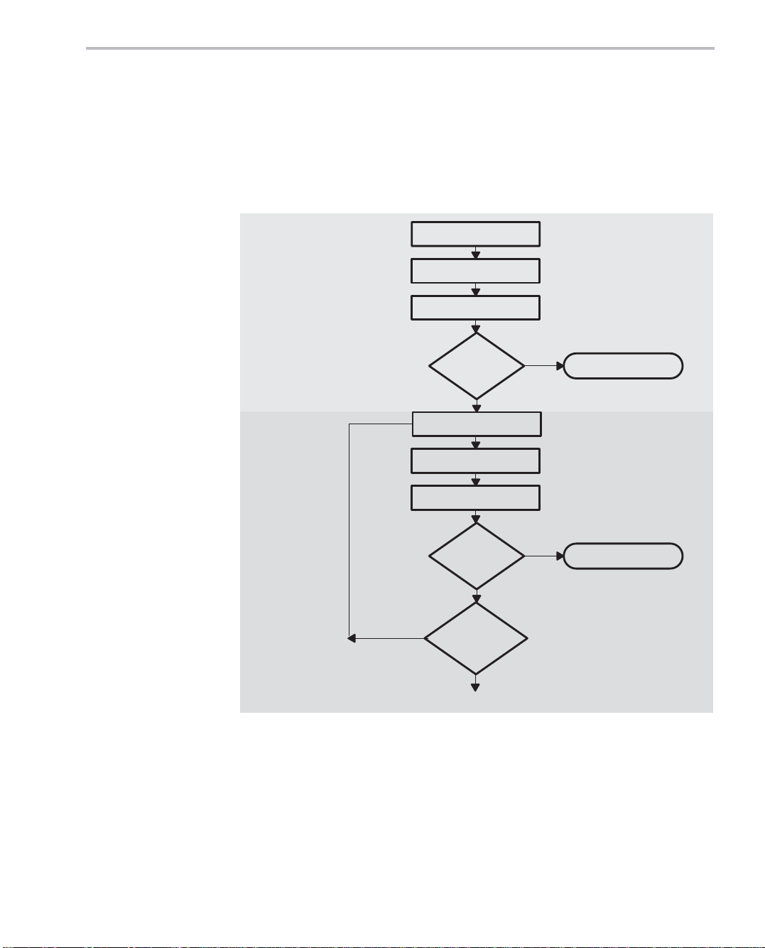
1.2 Code Development Flow for Best Performance
The following flow chart shows how to achieve the best performance and codegeneration efficiency from your code. After the chart, there is a table that describes the phases of the flow.
Figure 1−1. Code Development Flow
Step 1:
Write C Code
Step 2:
Optimize
C Code
Write C code
Optimize C code
Yes
optimization?
Compile
Profile
Efficient
enough?
No
Compile
Profile
Efficient
enough?
No
More C
Yes
Yes
Done
Done
No
To Step 3 (next page)
Introduction
1-3
Page 20
Code Development Flow for Best Performance
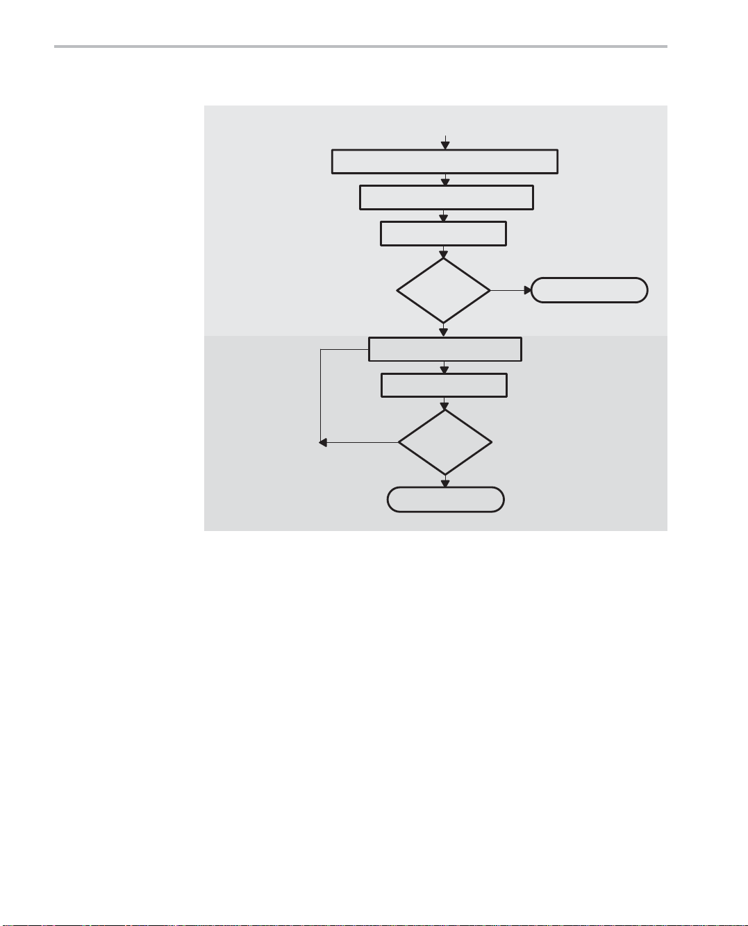
Figure 1−1. Code Development Flow (Continued)
From Step 2 (previous page)
Step 3:
Write
Assembly
Code
Step 4:
Optimize
Assembly
Code
Identify time-critical portions of C code
Write them in assembly code
Profile
Efficient
enough?
Yes
No
Optimize assembly code
Profile
No
Efficient
enough?
Yes
Done
Done
1-4
Page 21

Code Development Flow for Best Performance
Step
Goal
1 Write C Code: You can develop your code in C using the ANSI-
compliant C55x C compiler without any knowledge of the C55x DSP.
Use Code Composer Studio to identify any inefficient areas that
you might have in your C code. After making your code functional,
you can improve its performance by selecting higher-level optimization compiler options. If your code i s s ti l l n ot as efficient as you would
like it to be, proceed to step 2.
2 Optimize C Code: Explore potential modifications to your C code
to achieve better performance. Some of the techniques you can apply include (see Chapter 3):
- Use specific types (register, volatile, const).
- Modify the C code to better suit the C55x architecture.
- Use an ETSI intrinsic when applicable.
- Use C55x compiler intrinsics.
After modifying your code, use the C55x profiling tools again, to
check its performance. If your code is still not as efficient as you
would like it to be, proceed to step 3.
3 Write Assembly Code: Identify the time-critical portions of your C
code and rewrite them as C-callable assembly-language functions.
Again, profile your code, and if it is still not as efficient as you would
like it to be, proceed to step 4.
4
Optimize Assembly Code: After making your assembly code functional, try to optimize the assembly-language functions by using
some of the techniques described in Chapter 4, Optimizing Your As-
sembly Code. The techniques include:
- Place instructions in parallel.
- Rewrite or reorganize code to avoid pipeline protection delays.
- Minimize stalls in instruction fetching.
Introduction
1-5
Page 22

1-6
Page 23

Chapter 2
This tutorial walks you through the code development flow introduced in Chapter 1, and introduces you to basic concepts of TMS320C55x (C55x) DSP programming. It uses step-by-step instructions and code examples to show you
how to use the software development tools integrated under Code Composer
Studio (CCS).
Installing CCS before beginning the tutorial allows you to edit, build, and debug
DSP target programs. For more information about CCS features, see the CCS
Tutorial. You can access the CCS Tutorial within CCS by choosing
Help!Tutorial.
The examples in this tutorial use instructions from the mnemonic instruction
set, but the concepts apply equally for the algebraic instruction set.
Topic Page
2.1 Introduction 2-2. . . . . . . . . . . . . . . . . . . . . . . . . . . . . . . . . . . . . . . . . . . . . . . . . .
2.2 Writing Assembly Code 2-3. . . . . . . . . . . . . . . . . . . . . . . . . . . . . . . . . . . . . . .
2.3 Understanding the Linking Process 2-10. . . . . . . . . . . . . . . . . . . . . . . . . . .
2.4 Building Your Program 2-13. . . . . . . . . . . . . . . . . . . . . . . . . . . . . . . . . . . . . . .
2.5 Testing Your Code 2-19. . . . . . . . . . . . . . . . . . . . . . . . . . . . . . . . . . . . . . . . . . .
2.6 Benchmarking Your Code 2-21. . . . . . . . . . . . . . . . . . . . . . . . . . . . . . . . . . . . .
2-1
Page 24

Introduction
2.1 Introduction
This tutorial presents a simple assembly code example that adds four numbers together (y = x0 + x3 + x1 + x2). This example helps you become familiar
with the basics of C55x programming.
After completing the tutorial, you should know:
- The four common C55x addressing modes and when to use them.
- The basic C55x tools required to develop and test your software.
This tutorial does not replace the information presented in other C55x documentation and is not intended to cover all the topics required to program the
C55x efficiently.
Refer to the related documentation listed in the preface of this book for more
information about programming the C55x DSP. Much of this information has
been consolidated as part of the C55x Code Composer Studio online help.
For your convenience, all the files required to run this example can be downloaded with the TMS320C55x Programmer’s Guide (SPRU376) from
http://www.ti.com/sc/docs/schome.htm. The examples in this chapter can be
found in the 55xprgug_srccode\tutor directory.
2-2
Page 25

2.2 Writing Assembly Code
Writing your assembly code involves the following steps:
- Allocate sections for code, constants, and variables.
- Initialize the processor mode.
- Set up addressing modes and add the following values: x0 + x1 + x2 + x3.
The following rules should be considered when writing C55x assembly code:
- Labels
The first character of a label must be a letter or an underscore ( _ ) followed by a let t e r, and must begin in the first column of the text file. Labels
can contain up to 32 alphanumeric characters.
- Comments
When preceded by a semicolon ( ; ), a comment may begin in any column.
When preceded by an asterisk ( * ), a comment must begin in the first
column.
Writing Assembly Code
The final assembly code product of this tutorial is displayed in Example 2−1,
Final Assembly Code of tutor.asm. This code performs the addition of the elements in vector x. Sections of this code are highlighted in the three steps used
to create this example.
For more information about assembly syntax, see the TMS320C55x Assembly
Language Tools User’s Guide (SPRU280).
Tutorial
2-3
Page 26

Writing Assembly Code
Example 2−1. Final Assembly Code of tutor.asm
* Step 1: Section allocation
* −−−−−−
x .usect ”vars”,4 ; reserve 4 uninitalized 16-bit locations for x
y .usect ”vars”,1 ; reserve 1 uninitialized 16-bit location for y
.def x,y,init
init .int 1,2,3,4 ; contain initialization values for x
start
* Step 2: Processor mode initialization
* −−−−−−
BCLR C54CM ; set processor to ’55x native mode instead of
BCLR AR0LC ; set AR0 register in linear mode
BCLR AR6LC ; set AR6 register in linear mode
* Step 3a: Copy initialization values to vector x using indirect addressing
* −−−−−−−
copy
AMOV #x, XAR0 ; XAR0 pointing to variable x
AMOV #init, XAR6 ; XAR6 pointing to initialization table
MOV *AR6+, *AR0+ ; copy starts from ”init” to ”x”
MOV *AR6+, *AR0+
MOV *AR6+, *AR0+
MOV *AR6, *AR0
* Step 3b: Add values of vector x elements using direct addressing
* −−−−−−−
add
AMOV #x, XDP ; XDP pointing to variable x
.dp x ; and the assembler is notified
.sect ”table” ; create initialized section ”table” to
.text ; create code section (default is .text)
.def start ; define label to the start of the code
; ’54x compatibility mode (reset value)
MOV @x, AC0
ADD @(x+3), AC0
ADD @(x+1), AC0
ADD @(x+2), AC0
* Step 3c. Write the result to y using absolute addressing
* −−−−−−−
MOV AC0, *(#y)
end
NOP
B end
2-4
Page 27

2.2.1 Allocate Sections for Code, Constants, and Variables
The first step in writing this assembly code is to allocate memory space for the
different sections of your program.
Sections are modules consisting of code, constants, or variables needed to
successfully run your application. These modules are defined in the source file
using assembler directives. The following basic assembler directives are used
to create sections and initialize values in the example code.
- .sect “section_name” creates initialized name section for code/data. Ini-
tialized sections are sections defining their initial values.
- .usect “section_name”, size creates uninitialized named section for data.
Uninitialized sections declare only their size in 16-bit words, but do not define their initial values.
- .int value reserves a 16-bit word in memory and defines the initialization
value
- .def symbol makes a symbol global, known to external files, and indicates
that the symbol is defined in the current file. External files can access the
symbol by using the .ref directive. A symbol can be a label or a variable.
Writing Assembly Code
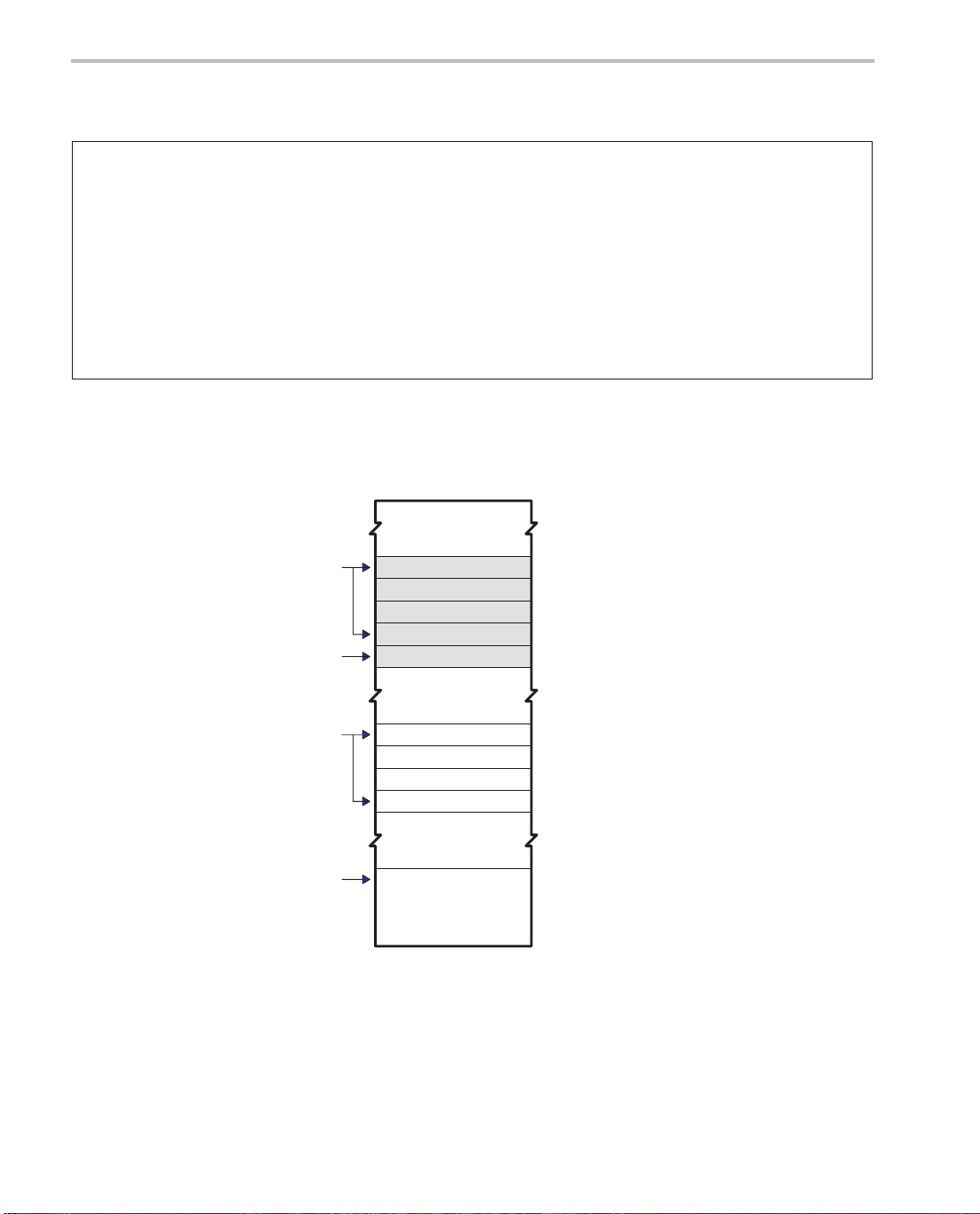
As shown in Example 2−2 and Figure 2−1, the example file tutor.asm contains
three sections:
- vars, containing five uninitialized memory locations
J The first four are reserved for vector x (the input vector to add).
J The last location, y, will be used to store the result of the addition.
- table, to hold the initialization values for x. The init label points to the begin-
ning of section table.
- .text, which contains the assembly code
Example 2−2 shows the partial assembly code used for allocating sections.
Tutorial
2-5
Page 28
Writing Assembly Code
Example 2−2. Partial Assembly Code of tutor.asm (Step 1)
* Step 1: Section allocation
* −−−−−−
.def x, y, init
x .usect “vars”, 4 ; reserve 4 uninitialized 16−bit locations for x
y .usect “vars”, 1 ; reserve 1 uninitialized 16−bit location for y
.sect “table” ; create initialized section “table” to
init .int 1, 2, 3, 4 ; contain initialization values for x
.text ; create code section (default is .text)
.def start ; define label to the start of the code
start
Note: The algebraic instructions code example for Partial Assembly Code of tutor.asm (Step 1) is shown in Example B−1 on
page B-2.
Figure 2−1. Section Allocation
x
y
Init
Start
1
2
3
4
Code
2-6
Page 29

2.2.2 Processor Mode Initialization
The second step is to make sure the status registers (ST0_55, ST1_55,
ST2_55, and ST3_55) are set to configure your processor . You will either need
to set these values or use the default values. Default values are placed in the
registers after processor reset. You can locate the default register values after
reset in the TMS320C55x DSP CPU Reference Guide (SPRU371).
As shown in Example 2−3:
- The AR0 and AR6 registers are set to linear addressing (instead of circular
addressing) using bit addressing mode to modify the status register bits.
- The processor has been set in C55x native mode instead of C54x-compat-
ible mode.
Example 2−3. Partial Assembly Code of tutor.asm (Step 2)
* Step 2: Processor mode initialization
* −−−−−−
BCLR C54CM ; set processor to ’55x native mode instead of
; ’54x compatibility mode (reset value)
BCLR AR0LC ; set AR0 register in linear mode
BCLR AR6LC ; set AR6 register in linear mode
Writing Assembly Code
Note: The algebraic instructions code example for Partial Assembly Code of tutor.asm (Step 2) is shown in Example B−2 on
page B-2.
Tutorial
2-7
Page 30

Writing Assembly Code
2.2.3 Setting up Addressing Modes
Four of the most common C55x addressing modes are used in this code:
- ARn Indirect addressing (identified by *), in which you use auxiliary regis-
ters (ARx) as pointers.
- DP direct addressing (identified by @), which provides a positive offset ad-
dressing from a base address specified by the DP register. The offset is
calculated by the assembler and defined by a 7-bit value embedded in the
instruction.
- k23 absolute addressing (identified by #), which allows you to specify the
entire 23-bit data address with a label.
- Bit addressing (identified by the bit instruction), which allows you to modify
a single bit of a memory location or MMR register.
For further details on these addressing modes, refer to the TMS320C55x DSP
CPU Reference Guide (SPRU371). Example 2−4 demonstrates the use of the
addressing modes discussed in this section.
In Step 3a, initialization values from the table section are copied to vector x (the
vector to perform the addition) using indirect addressing. Figure 2−2 illustrates
the structure of the extended auxiliar registers (XARn). The XARn register is
used only during register initialization. Subsequent operations use ARn because only the lower 16 bits are affected (ARn operations are restricted to a
64k main data page). AR6 is used to hold the address of table, and AR0 is used
to hold the address of x.
In Step 3b, direct addressing is used to add the four values. Notice that the
XDP register was initialized to point to variable x. The .dp assembler directive
is used to define the value of XDP, so the correct offset can be computed by
the assembler at compile time.
Finally , i n Step 3c, the result was stored in the y vector using absolute addressing. Absolute addressing provides an easy way to access a memory location
without having to make XDP changes, but at the expense of an increased code
size.
2-8
Page 31

Writing Assembly Code
n
Example 2−4. Partial Assembly Code of tutor.asm (Part3)
* Step 3a: Copy initialization values to vector x using indirect addressing
* −−−−−−−
copy
AMOV #x, XAR0 ; XAR0 pointing to variable x
AMOV #init, XAR6 ; XAR6 pointing to initialization table
MOV *AR6+, *AR0+ ; copy starts from ”init” to ”x”
MOV *AR6+, *AR0+
MOV *AR6+, *AR0+
MOV *AR6, *AR0
* Step 3b: Add values of vector x elements using direct addressing
* −−−−−−−
add
AMOV #x, XDP ; XDP pointing to variable x
.dp x ; and the assembler is notified
MOV @x, AC0
ADD @(x+3), AC0
ADD @(x+1), AC0
ADD @(x+2), AC0
* Step 3c: Write the result to y using absolute addressing
* −−−−−−−
MOV AC0, *(#y)
end
NOP
B end
Note: The algebraic instructions code example for Partial Assembly Code of tutor.asm (Part3) is shown in Example B−3 on
page B-3.
Figure 2−2. Extended Auxiliary Registers Structure (XARn)
22−16 15−0
XAR
Note: ARnH (upper 7 bits) specifies the 7-bit main data page. ARn (16-bit register) specifies a
ARnH
16-bit offset to the 7-bit main data page to form a 23-bit address.
ARn
Tutorial
2-9
Page 32

Understanding the Linking Process
2.3 Understanding the Linking Process
The linker (lnk55.exe) assigns the final addresses to your code and data sections. This is necessary for your code to execute.
The file that instructs the linker to assign the addresses is called the linker command file (tutor.cmd) and is shown in Example 2−5. The linker command file
syntax is covered in detail in the TMS320C55x Assembly Language Tools
User’s Guide (SPRU280).
- All addresses and lengths given in the linker command file uses byte ad-
dresses and byte lengths. This is in contrast to a TMS320C54x linker command file that uses 16-bit word addresses and word lengths.
- The MEMORY linker directive declares all the physical memory available
in your system (For example, a DARAM memory block at location 0x100
of length 0x8000 bytes). Memory blocks cannot overlap.
- The SECTIONS linker directive lists all the sections contained in your input
files and where you want the linker to allocate them.
When you build your project in Section 2.4, this code produces two files, tutor.out and a tutor.map. Review the test.map file, Example 2−6, to verify the
addresses for x, y, and table. Notice that the linker reports byte addresses for
program labels such as start and .text, and 16-bit word addresses for data labels like x, y , and table. The C55x DSP uses byte addressing to acces variable
length instructions. Instructions can be 1-6 bytes long.
Example 2−5. Linker command file (tutor.cmd)
MEMORY /* byte address, byte len */
{
DARAM: org= 000100h, len = 8000h
SARAM: org= 010000h, len = 8000h
}
SECTIONS /* byte address, byte len */
{
vars :> DARAM
table: > SARAM
.text:> SARAM
}
2-10
Page 33

Understanding the Linking Process
Example 2−6. Linker map file (test.map)
******************************************************************************
TMS320C55xx COFF Linker
******************************************************************************
>> Linked Mon Feb 14 14:52:21 2000
OUTPUT FILE NAME: <tutor.out>
ENTRY POINT SYMBOL: ”start” address: 00010008
MEMORY CONFIGURATION
name org (bytes) len (bytes) used (bytes) attributes fill
−−−− −−−−−−−−−−− −−−−−−−−−−− −−−−−−−−−−−− −−−−−−−−−− −−−−
DARAM 00000100 000008000 0000000a RWIX
SARAM 00010000 000008000 00000040 RWIX
SECTION ALLOCATION MAP
output attributes/
section page orgn(bytes) orgn(words) len(bytes) len(words) input sections
−−−−−−−− −−−− −−−−−−−−−−− −−−−−−−−−−− −−−−−−−−−− −−−−−−−−−− −−−−−−−−−−−−−−
vars 0 00000080 00000005 UNINITIALIZED
00000080 00000005 test.obj (vars)
table 0 00008000 00000004
00008000 00000004 test.obj
(table)
.text 0 00010008 00000038
00010008 00000037 test.obj
(.text)
0001003f 00000001 −−HOLE−− [fill
= 2020]
.data 0 00000000 00000000 UNINITIALIZED
00000000 00000000 test.obj
(.data)
.bss 0 00000000 00000000 UNINITIALIZED
00000000 00000000 test.obj (.bss)
Tutorial
2-11
Page 34

Understanding the Linking Process
Example 2−6. Linker map file (test.map), (Continued)
GLOBAL SYMBOLS: SORTED ALPHABETICALLY BY Name
abs. value/
byte addr word addr name
−−−−−−−−− −−−−−−−−− −−−−
00000000 .bss
00000000 .data
00010008 .text
00000000 ___bss__
00000000 ___data__
00000000 ___edata__
00000000 ___end__
00010040 ___etext__
00010008 ___text__
00000000 edata
00000000 end
00010040 etext
00008000 init
00010008 start
00000080 x
00000084 y
GLOBAL SYMBOLS: SORTED BY Symbol Address
abs. value/
byte addr word addr name
−−−−−−−−− −−−−−−−−− −−−−
00000000 ___end__
00000000 ___edata__
00000000 end
00000000 edata
00000000 ___data__
00000000 .data
00000000 .bss
00000000 ___bss__
00000080 x
00000084 y
00008000 init
00010008 start
00010008 .text
00010008 ___text__
00010040 ___etext__
00010040 etext
[16 symbols]
2-12
Page 35

2.4 Building Your Program
At this point, you should have already successfully installed CCS and selected
the C55x Simulator as the CCS configuration driver to use. Y ou can select the
configuration driver to be used in the CCS setup.
Before building your program, you must set up your work environment and
create a .pjt file. Setting up your work environment involves the following tasks:
- Creating a project
- Adding files to the work space
- Modifying the build options
- Building your program
2.4.1 Creating a Project
Create a new project called tutor.pjt.
1) From the Project menu, choose New and enter the values shown in
Figure 2−3.
Building Your Program
2) Select Finish.
You have now created a project named tutor.pjt and saved it in the new
c:\ti\myprojects\tutor folder.
Tutorial
2-13
Page 36

Building Your Program
Figure 2−3. Project Creation Dialog Box
2.4.2 Adding Files to the Workspace
Copy the tutorial files (tutor .asm and tutor.cmd) to the tutor project directory.
1) Navigate to the directory where the tutorial files are located (the
55xprgug_srccode\tutor directory) and copy them into the c:\ti\myprojects\tutor directory. As an alternative, you can create your own source
files by choosing File!New!Source File and typing the source code from
the examples in this book.
2) Add the two files to the tutor.pjt project. Highlight tutor.pjt, right-click the
mouse, select Add Files, browse for the tutor.asm file, select it, and click
Open, as shown in Figure 2−4. Do the same for tutor.cmd, as shown in
Figure 2−5.
2-14
Page 37

Figure 2−4. Add tutor.asm to Project
Building Your Program
Tutorial
2-15
Page 38

Building Your Program
Figure 2−5. Add tutor.cmd to Project
2-16
Page 39

2.4.3 Modifying Build Options
Modify the Linker options.
1) From the Project menu, choose Build Options.
2) Select the Linker tab and enter fields as shown in Figure 2−6.
3) Click OK when finished.
Figure 2−6. Build Options Dialog Box
Building Your Program
Tutorial
2-17
Page 40

Building Your Program
2.4.4 Building the Program
From the Project menu, choose Rebuild All. After the Rebuild process
completes, the screen shown in Figure 2−7 should display.
When you build your project, CCS compiles, assembles, and links your code
in one step. The assembler reads the assembly source file and converts C55x
instructions to their corresponding binary encoding. The result of the assembly
processes is an object file, tutor.obj, in industry standard COFF binary format.
The object file contains all of your code and variables, but the addresses for
the different sections of code are not assigned. This assignment takes place
during the linking process.
Because there is no C code in your project, no compiler options were used.
Figure 2−7. Rebuild Complete Screen
2-18
Page 41

2.5 Testing Your Code
To test your code, inspect its execution using the C55x Simulator.
Load tutor.out
1) From the File menu, choose Load program.
2) Navigate to and select tutor.out (in the \debug directory), then choose
CCS now displays the tutor.asm source code at the beginning of the start label
because of the entry symbol defined in the linker command file (-e start).
Otherwise, it would have shown the location pointed to by the reset vector.
Display arrays x, y, and init by setting Memory Window options
1) From the View menu, choose Memory.
2) In the Title field, type x.
3) In the Address field, type x.
Testing Your Code
Open.
4) Repeat 1−3 for y.
5) Display the init array by selecting View→ Memory.
6) In the Title field, type Table.
7) In the Address field, type init.
8) Display AC0 by selecting View→CPU Registers→CPU Registers.
The labels x, y, and init are visible to the simulator (using View→ Memory) be-
cause they were exported as symbols (using the .def directive in tutor.asm).
The -g option was used to enable assembly source debugging.
Now, single-step through the code to the end label by selecting Debug→Step
Into. Examine the X Memory window to verify that the table values populate
x and that y gets the value 0xa (1 + 2 + 3 + 4 = 10 = 0xa), as shown in
Example 2−7.
Tutorial
2-19
Page 42

Testing Your Code
Example 2−7. x Memory Window
2-20
Page 43

2.6 Benchmarking Your Code
After verifying the correct functional operation of your code, you can use CCS
to calculate the number of cycles your code takes to execute.
Reload your code
From the File menu, choose Reload Program.
Enable clock for profiling
1) From the Profiler menu, choose Enable Clock.
2) From the Profiler menu, choose View Clock.
Set breakpoints
1) Select the tutor.asm window.
2) Set one breakpoint at the beginning of the code you want to benchmark
(first instruction after start): Right-click on the instruction next to the copy
label and choose Toggle Breakpoint.
Benchmarking Your Code
3) Set one breakpoint marking the end: Right-click on the instruction next to
the end label and choose Toggle Breakpoint.
Benchmark your code
1) Run to the first breakpoint by selecting Debug→ Run.
2) Double-click in the Clock Window to clear the cycle count.
3) Run to the second breakpoint by selecting Debug→ Run.
4) The Clock Window displays the number of cycles the code took to execute
between the breakpoints, which was approximately 17.
Tutorial
2-21
Page 44

2-22
Page 45

Chapter 3
You can maximize the performance of your C code by using certain compiler
options, C code transformations, and compiler intrinsics. This chapter discusses features of the C language relevant to compilation on the
TMS320C55x (C55x) DSP, performance-enhancing options for the compiler,
and C55x-specific code transformations that improve C code performance. All
assembly language examples were generated for the large memory model via
the −ml compiler option.
Topic Page
3.1 Introduction to Writing C/C++ Code for a C55x DSP 3-2. . . . . . . . . . . . . .
3.2 Compiling the C/C++ Code 3-7. . . . . . . . . . . . . . . . . . . . . . . . . . . . . . . . . . . . .
3.3 Profiling Your Code 3-13. . . . . . . . . . . . . . . . . . . . . . . . . . . . . . . . . . . . . . . . . .
3.4 Refining the C/C++ Code 3-15. . . . . . . . . . . . . . . . . . . . . . . . . . . . . . . . . . . . .
3.5 Memory Management Issues 3-42. . . . . . . . . . . . . . . . . . . . . . . . . . . . . . . . . .
3-1
Page 46

Introduction to Writing C/C++ Code for a C55x DSP
3.1 Introduction to Writing C/C++ Code for a C55x DSP
This section describes some general issues to keep in mind when writing
C/C++ code for the TMS320C55x (C55x) architecture (or any DSP architecture). Keep this information in mind when working in Step 1 of code development as described in Chapter 1. Refer to TMS320C55x Optimizing C/C++
Compiler User’s Guide (SPRU281) for additional language issues.
3.1.1 Tips on Data Types
Give careful consideration to the data type size when writing your code. The
C55x compiler defines a size for each C data type (signed and unsigned):
char 16 bits
short 16 bits
int 16 bits
long 32 bits
long long 40 bits
float 32 bits
double 64 bits
Floating point values are in the IEEE format. Based on the size of each data
type, follow these guidelines when writing your code:
- Avoid code that assumes that int and long types are the same size.
- Use the int data type for fixed-point arithmetic (especially multiplication)
whenever possible. Using type long for multiplication operands will result
in calls to a run-time library routine.
- Use int or unsigned int types rather than long for loop counters.
The C55x has mechanisms for efficient hardware loops, but hardware
loop counters are only 16 bits wide.
- Avoid code that assumes char is 8 bits or long long is 64 bits.
When writing code to be used on multiple DSP targets, it may be wise to define
“generic” types for the standard C types. For example, one could use the types
Int16 and Int32 for a 16 bit integer type and 32 bit integer type respectively.
When compiling for the C55x DSP, these types would be type defined to int
and long, respectively.
In general it is best to use the type int for loop index variables and other inte-
ger variables where the number of bits is unimportant as int typically repre-
sents the most efficient integer type for the target to manipulate, regardless of
architecture.
3-2
Page 47

Introduction to Writing C/C++ Code for a C55x DSP
3.1.2 How to Write Multiplication Expressions Correctly in C Code
Writing multiplication expressions in C code so that they are both correct and
efficient can be confusing, especially when technically illegal expressions can,
in some circumstances, generate the code you wanted in the first place. This
section will help you choose the correct expression for your algorithm.
The correct expression for a 16x16−>32 multiplication on a C55x DSP is:
long res = (long)(int)src1 * (long)(int)src2;
According to the C arithmetic rules,this is actually a 32x32−>32 multiplication,
but the compiler will notice that each operand fits in 16 bits, so it will issue an
efficient single-instruction multiplication.
A 16-bit multiplication with a 32-bit result is an operation which does not directly exist in the C language, but does exist on C55x hardware, and is vital for multiply-and-accumulate (MAC)-like algorithm performance.
Example 3−1 shows two incorrect ways and a correct way to write such a multiplication in C code.
Example 3−1. Generating a 16x16−>32 Multiply
long mult(int a, int b)
{
long result;
/* incorrect */
result = a * b;
/* incorrect */
result = (long)(a * b);
/* correct */
result = (long)a * b;
return result;
}
Note that the same rules also apply for other C arithmetic operators. For example, if you want to add two 16-bit numbers and get a full 32 bit result, the correct
syntax is:
(long) res = (long)(int)src1 + (long)(int)src;
Optimizing C Code
3-3
Page 48

Introduction to Writing C/C++ Code for a C55x DSP
3.1.3 Memory Dependences
To maximize the efficiency or your code, the C55x compiler reorders instructions to minimize pipeline stalls, puts certain assembly instructions in parallel,
and generates dual multiply-and-accumulate (dual-MAC) instructions. These
transformations require the compiler to determine the relationships, or dependences, between instructions. Dependence means that one instruction must
occur before another. For example, a variable may need to be loaded from
memory before it can be used. Because only independent instructions can be
scheduled in parallel or reordered, dependences inhibit parallelism and code
movement. If the compiler cannot prove that two instructions are independent,
it must assume that instructions must remain in the order they originally appeared and must not be scheduled in parallel.
Often it is difficult for the compiler to determine whether instructions that access memory are independent. The following techniques help the compiler determine which instructions are independent:
- Use the restrict keyword to indicate that a pointer is the only pointer
than can point to a particular object in the scope in which the pointer is declared.
- Use the –pm option which gives the compiler global access to the whole
program and allows it to be more aggressive in ruling out dependences.
To illustrate the concept of memory dependences, it is helpful to look at the algorithm code in a dependence graph. Example 3−2 shows code for a simple
vector sum. Figure 3−1 shows a simplified dependence graph for that piece of
code.
Example 3−2. C Code for Vector Sum
void vecsum(int *sum, short *in1, short *in2, int N)
{
int i;
for (i = 0; i < N; i++)
sum[i] = in1[i] + in2[i];
}
3-4
Page 49

Figure 3−1. Dependence Graph for Vector Sum
Introduction to Writing C/C++ Code for a C55x DSP
Load
in1[i]
Add
Store
sum[i]
Load
in2[i]
The dependence graph in Figure 3−1 shows that:
- The paths from the store of sum[i] back to the loads of in1[i] and
in2[i] indicate that writing to sum may have an effect on the memory
pointed to by either in1 or in2.
- A read from in1 or in2 cannot begin until the write to sum finishes, which
creates an aliasing problem. Aliasing occurs when two pointers can point
to the same memory location. For example, if vecsum() is called in a program with the following statements, in1 and sum alias each other because they both point to the same memory location:
short a[10], b[10];
vecsum(a, a, b, 10);
To help the compiler resolve memory dependences, you can qualify a pointer
or array with the restrict keyword. Its use represents a guarantee by the
programmer that within the scope of the pointer declaration, the object pointed
to can be accessed only by that pointer. Any violation of this guarantee renders
the behavior of the program undefined. This practice helps the compiler optimize certain sections of code because aliasing information can be more easily
determined.
In the declaration of the vector sum function you can use the restrict key-
word to tell the compiler that sum is the only pointer that points to that object:
void vecsum(int * restrict sum, int *in1, int *in2, int N)
Optimizing C Code
3-5
Page 50

Introduction to Writing C/C++ Code for a C55x DSP
(Likewise, you could add restrict to in1 and in2 as well.) The next piece of
code shows how to us e restrict with an array function parameter instead of
a pointer:
void vecsum(int sum[restrict], int *in1, int *in2, int N)
Caution must be exercised when using restrict. Consider this call of vecsum()
(with the sum parameter qualified by restrict):
vecsum(a, a, b, 10);
Undefined behavior would result because sum and in1 would point to the
same object, which violates sum’s declaration as restrict.
3.1.4 Analyzing C Code Performance
Use the following techniques to analyze the performance of specific code regions:
- Use the clock() and printf() functions in C/C++ code to time and dis-
play the performance of specific code regions. You can use the standalone simulator (load55) for this purpose. Remember to subtract out the
overhead time of calling the clock() function.
- Enable the clock and use profile points and the RUN command in the Code
Composer Studio debugger to track the number of CPU clock cycles consumed by a particular section of code.
- Put each loop into a separate file that can be rewritten, recompiled, and
run with the stand-alone simulator (load55).The critical performance
areas in your code are most often loops.
As you use the techniques described in this chapter to optimize your C/C++
code, you can then evaluate the performance results by running the code and
looking at the instructions generated by the compiler. More detail on performance analysis can be found in section 3.3.
3-6
Page 51

3.2 Compiling the C/C++ Code
The C55x compiler offers high-level language support by transforming your
C/C++ code into assembly language source code. The compiler tools include
a shell program (cl55), which you use to compile, optimize, assemble, and link
programs in a single step. To invoke the compiler shell, enter:
cl55 [options] [filenames] [−z [linker options] [object files]]
For a complete description of the C/C++ compiler and the options discussed in
this section, see the TMS320C55x Optimizing C Compiler User’s Guide
(SPRU281).
3.2.1 Compiler Options
Options control the operation of the compiler. This section introduces you to
the recommended options for performance, information gathering, and code
size.
First make note of the options to avoid using on performance critical code.The
options described in Table 3−1 are intended for debugging, and could potentially decrease performance and increase code size.
Compiling the C/C++ Code
Table 3−1. Compiler Options to Avoid on Performance-Critical Code
Option Description
−g, −s, −ss, −gp These options are intended for debugging and can limit the
amount of optimization across C statements leading to larger
code size and slower execution.
−o1, −o0 Always use −o2/−o3 to maximize compiler analysis and optimization
−mr
The options in Table 3−2 can be used to improve performance. The options
−o3, −pm, −mb, −oi50, and −op2 are recommended for maximum performance.
Prevents generation of hardware loops to reduce context
save/restore for interrupts. As hardware loops greatly improve
performance of loop code, avoid this option on performance
critical code.
Optimizing C Code
3-7
Page 52

Compiling the C/C++ Code
Table 3−2. Compiler Options for Performance
Option Description
−o3 Represents the highest level of optimization available. Various loop
optimizations are performed, and various file-level characteristics
are also used to improve performance.
−pm Combines source files to perform program-level optimization by
allowing the compiler visibility to the entire application source.
−oi<size> Enables inlining of functions based on a maximum size. (Enabled
with −o3.) Size here is determined internally by the optimizer and
does not correspond to bytes or any other known standard unit.
Use a −onx option to check sizes of individual functions.
−mb Asserts to the compiler that all data is on-chip. This option is used
to enable the compiler to generate dual-MAC. See section 3.4.2.2
for more details.
−op2 When used with −pm, this option allows the compiler to assume
that the program being compiled does not contain any functions or
variables called or modified from outside the current file. The compiler is free to remove any functions or variables that are unused in
the current file.
−mn
Re-enables optimizations disabled when using −g option (symbolic
debugging). Use this option when it is necessary to debug optimized code.
The options described in Table 3−3, can be used to improve code size with a
possible degradation in performance.
Table 3−3. Compiler Options That May Degrade Performance and Improve Code Size
Option Description
−ms Encourages the compiler to optimize for code space. (Default is to
optimize for performance.)
−oi0 Disables all automatic size-controlled inlining enabled by −o3.
User specified inlining of functions is still allowed.
The options described in Table 3−4 provide information to the programmer.
Some of them may negatively affect performance and/or code size.
3-8
Page 53

Table 3−4. Compiler Options for Information
Option Description
−k The assembly file is not deleted. This allows you to inspect the
generated code. This option has no impact on performance or
code size.
−s/−ss Interlists optimizer comments/C source in the assembly. The −s
option may show minor performance degradation. The –ss option
may show more severe performance degradation.
−mg Generate algebraic assembly code. (Default is mnemonic.) There
is no performance or code size impact.
−onx When x is 1, the optimizer generates an information file (.nfo file-
name extension). When x is 2, a more verbose information file is
generated. There is no performance or code size impact.
3.2.2 Performing Program-Level Optimization (−pm Option)
You can specify program-level optimization by using the −pm option with the
−o3 option. With program-level optimization, all your source files are compiled
into one intermediate file giving the compiler complete program view during
compilation. Because the compiler has access to the entire program, it performs several optimizations that are rarely applied during file-level optimization:
Compiling the C/C++ Code
- If the number of iterations of a loop is determined by a value passed into
the function and the compiler can determine what the value is from the calling function, the compiler will have more information about the number of
iterations of the loop, resulting in more efficient loop code.
- If a particular argument to a function always has the same value, the com-
piler replaces the occurrences of the argument in the function with the
value.
- If a return value of a function is never used, the compiler deletes the return
code in the function.
- If a function is not called, directly or indirectly, the compiler removes the
code in the function.
Program-level optimization increases compilation time because the compiler
performs more complex optimizations on a larger amount of code. For this reason you may not want to use this option for every build of large programs.
Example 3−3 and Example 3−4 show the content of two files. One file contains
the source for the main function and the second file contains source for a small
function called sum.
Optimizing C Code
3-9
Page 54

Compiling the C/C++ Code
Example 3−3. Main Function File
extern int sum(const int *a, int n);
const int a[10] = {1,2,3,4,5,6,7,8,9,10};
const int b[10] = {11,12,13,14,15,16,17,18,19,20};
int sum1, sum2;
int main(void)
{
sum1 = sum(a,10);
sum2 = sum(b,10);
return(0);
}
Example 3−4. Sum Function File
int sum(const int *a, int n)
{
int total = 0;
int i;
for(i=0; i<n; i++)
{
total += a[i];
}
return total;
}
3-10
When this code is compiled with −o3 and −pm options, the optimizer has
enough information about the calls to sum to determine that the same loop
count is used for both calls. It therefore eliminates the argument n from the call
to the function and explicitly uses the count in the repeat single instruction as
shown in Example 3−5.
Page 55

Compiling the C/C++ Code
Example 3−5. Assembly Code Generated With −o3 and −pm Options
_sum:
;** Parameter deleted n == 9u
MOV #0, T0 ; |3|
RPT #9
ADD *AR0+, T0, T0
return ; |11|
_main:
AADD #−1, SP
AMOV #_a, XAR0 ; |9|
call #_sum ; |9|
; call occurs [#_sum] ; |9|
MOV T0, *(#_sum1) ; |9|
AMOV #_b, XAR0 ; |10|
call #_sum ; |10|
; call occurs [#_sum] ; |10|
MOV T0, *(#_sum2) ; |10|
AADD #1, SP
return
; return occurs
Note: The algebraic instructions code example for Assembly Code Generated With −o3 and −pm Options is shown in
Example B−4 on page B-4.
Caution must be exercised when using program mode (−pm) compilation on
code that consists of a mixture of C/C++ and assembly language functions.
These issues are described in detail in the TMS320C55x Optimizing C Compil-
er User’s Guide (SPRU281).
3.2.3 Using Function Inlining
There are two ways to enable the compiler to inline functions:
- Inlining controlled by the inline keyword. To enable this mode you must
run the optimizer (that is, you must choose at least −o0.)
- Automatic inlining of small functions that are not declared as inline in
your C/C++ code. To enable this mode use the −o3 and −oi<size> compiler options.
Optimizing C Code
3-11
Page 56

Compiling the C/C++ Code
The −oi<size> option may be used to specify automatic inlining of small
functions even if they have not been declared with the inline keyword. The
size of a function is an internal compiler notion of size. To see the size of a particular function use the −onx options described in Table 3−4 on page 3-9.
Example 3−6 shows the resulting assembly instructions when the code in
Example 3−3 and Example 3−4 is compiled with −o3, −pm, and −oi50 op-
tions.
In main, the function calls to sum have been inlined. However, code for the
body of function sum has still been generated. The compiler must generate this
code because it does not have enough information to eliminate the possibility
that the function sum may be called by some other externally defined function.
If no external function calls sum, it can be declared as static inline. The
compiler will then be able to eliminate the code for sum after inlining.
Example 3−6. Assembly Generated Using −o3, −pm, and −oi50
_sum:
MOV #0, T0 ; |3|
RPT #9
ADD *AR0+, T0, T0
return ; |11|
_main:
AMOV #_a, XAR3 ; |9|
RPT #9
|| MOV #0, AR1 ; |3|
ADD *AR3+, AR1, AR1
MOV AR1, *(#_sum1) ; |11|
MOV #0, AR1 ; |3|
AMOV #_b, XAR3 ; |10|
RPT #9
ADD *AR3+, AR1, AR1
MOV AR1, *(#_sum2) ; |11|
return
Note: The algebraic instructions code example for Assembly Generated Using −o3, −pm, and −oi50 is shown in Example B−5
3-12
on page B-5.
Page 57

3.3 Profiling Your Code
In large applications, it makes sense to optimize the most important sections of
code first. You can use the information generated by profiling options to get
started. This section describes profiling methods to determine whether to
move from Step 1 to Step 2 of the code development flow as described in
Chapter 1 (or from Step 2 to Step 3). You can use several different methods to
profile your code.
3.3.1 Using the clock() Function to Profile
To get cycle count information for a function or region of code with the standalone simulator, embed the clock() function in your C code. Example 3−7
demonstrates this technique.
Example 3−7. Using the clock() Function
#include <stdio.h>
#include <time.h> /* Need time.h in order to call clock() */
int main()
{
clock_t start, stop, overhead;
start = clock(); /* Calculate the overhead of calling clock */
stop = clock(); /* and subtract this amount from the results. */
overhead = stop − start;
start = clock();
/* Function or Code Region to time goes here */
stop = clock();
printf(”cycles: %ld\n”,(long)(stop − start – overhead));
return(0);
}
Profiling Your Code
Caution: Using clock() to time a region of code could increase the cycle
count of that region due to the extra variables needed to hold the timing information (the stop, start, and overhead variables above). Wrapping
clock() around a function call should not affect the cycle count of that function.
Optimizing C Code
3-13
Page 58

Profiling Your Code
3.3.2 Using CCS 2.0 to Profile
Code Composer Studio (CCS) 2.0 has extensive profiling options that can be
used to profile your C code. First you must enable the clock by selecting Enable Clock from the Profiler menu. Selecting Start New Session from the Profiler menu starts a new profiling session. To profile all functions, click on the Profile All Functions button in the profiler session window. To profile certain functions or regions of code, click the Create Profile Area and enter the starting and
ending line numbers of the code you wish to profile. (Note that you must build
your code for debugging (−g option) to enable this feature.) Then, run your program and the profile information will be updated in the profiler session window .
More information on profiling with CCS 2.0 can be found in the online documentation.
3-14
Page 59

3.4 Refining the C/C++ Code
This section describes C55x-specific optimization techniques that you can use
to improve your C/C++ code performance. These techniques should be used
in Step 2 of the code development flow as described in Chapter 1. Consider
these tips when refining your code:
- Create loops that efficiently use C55x hardware loops, MAC hardware,
and dual-MAC hardware.
- Use intrinsics to replace complicated C/C++ code
- Avoid the modulus operator when simulating circular addressing
- Use long accesses to reference 16-bit data in memory
- Write efficient control code
It is recommended that the following optimization techniques be applied in the
order presented here. The code can be profiled after implementing the optimization described in each section to determine if further optimization is needed. If so, proceed to the next optimization. The six techniques presented in this
section are summarized in Table 3−5. The indications (high, moderate, low,
easy, many, some, few) in the table apply to typical DSP code. Potential per-
formance gain estimates the performance improvement over no modifications to the code. Ease of implementation reflects both the required amount
of change to the code and the complexity of the optimization. Opportunities
are the number of places the optimization can be applied in typical DSP code.
Refining the C/C++ Code
Table 3−5. Summary of C/C++ Code Optimization Techniques
Potential
Optimization Technique
Generate efficient loop
code
Use MAC hardware
efficiently
Use Intrinsics High Moderate Many Reduces portability
Avoid modulus in circular
addressing
Use long accesses for
16-bit data
Generate efficient control
code
Performance Gain
High Easy Many
High Moderate Many
Moderate Easy Some
Low Moderate Few
Low Easy Few
Ease of
Implementation
Opportunities Issues
Optimizing C Code
3-15
Page 60

Refining the C/C++ Code
3.4.1 Generating Efficient Loop Code
You can realize substantial gains from the performance of your C/C++ loop
code by refining your code in the following areas:
- Avoid function calls within the body of repeated loops. This enables the
compiler to use very efficient hardware looping constructs (repeat,
localrepeat, and blockrepeat, or RPT, RPTBLOCAL, and RPTB in
mnemonic syntax).
- Keep loop code small to enable the compiler to use localrepeat.
- Analyze trip count issues.
- Use the MUST_ITERATE pragma.
- Use the −o3 and −pm compiler options.
3.4.1.1 Avoid Function Calls within Loops
Whenever possible avoid using function calls within loops. Because repeat labels and counts would have to be preserved across calls, the compiler decides
never to generate hardware loops that contain function calls. This leads to inefficient loop code.
3.4.1.2 Keep Loops Small to Enable localrepeat
Keeping loop code small enables the compiler to make use of the native
localrepeat instruction. The compiler will generate localrepeat for
small loops that do not contain any control flow structures other than forward
conditionals. Localrepeat loops consume less power than other looping
constructs. An example of a small loop that can use localrepeat is shown in
Example 3−8 and Example 3−9. Example 3−8 shows C code and
Example 3−9 shows the assembly code generated by the compiler.
Example 3−8. Simple Loop That Allows Use of localrepeat
void vecsum(const short *a, const short *b, short *c, unsigned int n)
{
unsigned int i;
for (i=0; i<=n−1; i++)
{
*c++ = *a++ + *b++;
}
}
3-16
Page 61

Refining the C/C++ Code
Example 3−9. Assembly Code for localrepeat Generated by the Compiler
_vecsum:
SUB #1, T0, AR3
MOV AR3, BRC0
RPTBLOCAL L2−1
ADD *AR0+, *AR1+, AC0 ; |7|
MOV HI(AC0), *AR2+ ; |7|
L2:
return
Note: The algebraic instructions code example for Assembly Code for localrepeat Generated by the Compiler is shown in
Example B−6 on page B-5.
3.4.1.3 Trip Count Issues
A trip count is the number of times that a loop executes; the trip counter is the
variable used to count each iteration. When the trip counter reaches the limit
equal to the trip count, the loop terminates. Maximum performance for loop
code is gained when the compiler can determine the exact minimum and maximum for the trip count. T o this end, use the following techniques to convey trip
count information to the compiler:
- Use int (or unsigned int) type for trip counter variable, whenever
possible.
- Use the MUST_ITERATE pragma to eliminate code to skip around loops
and help the compiler generate efficient hardware loops. This pragma can
also be used to aid in loop unrolling.
- Be sure to use the −o3 and −pm compiler options to allow the optimizer
access to the whole program or large parts of it and to characterize the behavior of loop trip counts.
Using int Type. Using the type int for the trip counter is important to allow
the compiler to generate hardware looping constructs.
In Example 3−10, consider this simple for loop:
for(i = 0; i<n; i++)
If, for example, i and n were declared to be of type long, no hardware loop
could be generated. This is because the C55x internal loop iteration count register is only 16 bits wide. If i and n are declared as type int, then the compiler
will generate a hardware loop.
Optimizing C Code
3-17
Page 62

Refining the C/C++ Code
3.4.1.4 Using the MUST_ITERATE Pragma
The MUST_ITERATE pragma is used to convey programmer knowledge about
loops to the compiler. It should be used as much as possible to aid the compiler
in the optimization of loops.
Example 3−10 shows code to compute the sum of a vector . The corresponding
assembly code is shown in Example 3−11. Notice the conditional branch that
jumps around the loop body in the generated assembly code. The compiler
must insert this additional code if there is any possibility that the loop could execute zero times. In this particular case the loop upper bound n is an integer.
Thus, n could be zero or negative in which case C semantics would dictate that
the for loop body would not execute. A hardware loop must execute at least
once, so the jump around code ensures correct execution in cases where
n <= 0.
Example 3−10. Inefficient Loop Code for Loop Variable and Constraints (C)
int sum(const short *a, int n)
{
int sum = 0;
int i;
for(i=0; i<n; i++)
{
sum += a[i];
}
return sum;
}
3-18
Page 63

Refining the C/C++ Code
Example 3−11. Inefficient Loop Code for Variable and Constraints (Assembly)
_sum:
MOV #0, AR1 ; |3|
BCC L2,T0 <= #0 ; |6|
; branch occurs ; |6|
SUB #1, T0, AR2
MOV AR2, CSR
RPT CSR
ADD *AR0+, AR1, AR1
MOV AR1, T0 ; |11|
return ; |11|
Note: The algebraic instructions code example for Inefficient Loop Code for V ariable and Constraints (Assembly) is shown in
Example B−7 on page B-6.
If it is known that the loop always executes at least once, this fact can be communicated to the compiler via the MUST_ITERATE pragma. Example 3−12
shows how to use the pragma for this piece of code. Example 3−13 shows the
more efficient assembly code that can now be generated because of the pragma.
Example 3−12. Using the MUST_ITERATE Pragma
int sum(const short *a, int n)
{
int sum = 0;
int i;
#pragma MUST_ITERATE(1)
for(i=0; i<n; i++)
{
sum += a[i];
}
return sum;
}
(Note that the same effect could be generated by using an _nassert, to assert to the compiler that n is greater than zero: _nassert(n>0
Optimizing C Code
)).
3-19
Page 64

Refining the C/C++ Code
Example 3−13. Assembly Code Generated With the MUST_ITERATE Pragma
_sum:
SUB #1, T0, AR2
MOV AR2, CSR
MOV #0, AR1 ; |3|
RPT CSR
ADD *AR0+, AR1, AR1
MOV AR1, T0 ; |12|
return ; |12|
Note: The algebraic instructions code example for Assembly Code Generated With the MUST_ITERATE Pragma is shown in
Example B−8 on page B-6.
MUST_ITERATE can be used to communicate several different pieces of information to the compiler. The format of the pragma is:
#pragma MUST_ITERATE(min, max, mult)
All fields are optional. min is the minimum number of iterations of the loop, max
is the maximum number of iterations of the loop, and mult tells the compiler
that the l o o p always executes a multiple of
mult times. If some of these values
are not known until run time, do not include them in the pragma. Incorrect information communicated via the pragma could result in undefined program behavior. The MUST_ITERATE pragma must appear immediately before the loop
that it is meant to describe in the C code. MUST_ITERATE can be used in the
following ways:
- It can convey that the trip count will be greater than some minimum value.
/* This loop will always execute at least 30 times */
#pragma MUST_ITERATE(30)
for(j=0; j<x; j++)
- It can convey the maximum trip count.
/* The loop will execute no more than 100 times */
#pragma MUST_ITERATE(,100)
for (j=0; j<x; j++)
3-20
- It can convey that the trip count is always divisible by a value.
/* The loop will execute some multiple of 4 times */
#pragma MUST_ITERATE(,,4)
for (j=0; j<x; j++)
Page 65

Consider the following loop header (from the ETSI gsmefr benchmark):
for(i=a[0]; i < 40; i +=5)
To generate a hardware loop, the compiler would need to emit code that would
determine the number of loop iterations at run time. This code would require an
integer division. Since this is computationally expensive, the compiler will not
generate such code and will not generate a hardware loop. However , if the programmer knows that, for example, a[0] is always less than or equal to 4, then
the loop always executes exactly eight times. This can be communicated via a
MUST_ITERATE pragma enabling the compiler to generate an efficient hardware loop:
#pragma MUST_ITERATE(8,8)
3.4.2 Efficient Use of MAC hardware
Multiply-and-accumulate (MAC) is a very common paradigm in DSP algorithms, and a C55x DSP has hardware to perform MAC operations efficiently. It
can perform a single MAC (or multiply, multiply and subtract) operation or two
MAC operations in a single cycle (a dual-MAC operation). The next section describes how to write efficient, small loops that use a single MAC operation.
Section 3.4.2.2 describes how to enable the compiler to generate dual-MAC
operations from your C/C++ code.
Refining the C/C++ Code
3.4.2.1 Special Considerations When Using MAC Constructs
The compiler can generate a very efficient single repeat MAC construct (that
is, a repeat (RPT) loop with a MAC as its only instruction.) To facilitate the
generation of single repeat MAC constructs, use local rather than global variables for the summation, as shown in Example 3−14. If a global variable is
used, the compiler is obligated to perform an intervening storage to the global
object. This prevents it from generating a single repeat.
In the case where Q15 arithmetic is being simulated, the result of the MAC operation may be accumulated into a long object. The result may then be shifted
and truncated before the return, as shown in Example 3−15.
Optimizing C Code
3-21
Page 66

Refining the C/C++ Code
Example 3−14. Use Local Rather Than Global Summation Variables
/* Not recommended */
int gsum=0;
void dotp1(const int *x, const int *y, unsigned int n)
{
unsigned int i;
for(i=0; i<=n−1; i++)
gsum += x[i] * y[i];
}
/* Recommended */
int dotp2(const int *x, const int *y, unsigned int n)
{
unsigned int i;
int lsum=0;
for(i=0; i<=n−1; i++)
lsum += x[i] * y[i];
return lsum;
}
Example 3−15. Returning Q15 Result for Multiply Accumulate
int dotp(const int *x, const int *y, unsigned int n)
{
unsigned int i;
long sum=0;
for(i=0; i<=n−1; i++)
sum += (long)x[i] * y[i];
return (int)((sum>>15) & 0x0000FFFFL);
}
3.4.2.2 Generating Dual-MAC Operations
A dual-MAC operation (2 multiply-and-accumulate/subtract instructions in a
single cycle) is one of the most important hardware features of a C55x DSP.
(Note, the term dual-MAC will be used to refer to dual multiplies, dual multiplyand-accumulates and dual multiply-and-subtracts.) You must follow several
guidelines in your C code to help the compiler generate dual-MAC operations.
3-22
Page 67

Refining the C/C++ Code
In order for the compiler to generate a dual-MAC operation, the code must
have two consecutive MAC (or MAS/multiply) instructions that get all their multiplicands from memory and share one multiplicand. The two operations must
not write their results to the same variable or location. The compiler can easily
turn this example into a dual-MAC:
int *a,*b, onchip *c;
long s1,s2;
[...]
s1 = s1 + (*a++ * *c);
s2 = s2 + (*b++ * *c++);
This is a sequence of two MAC instructions that share the *c memory reference. Intrinsics can also be transformed into dual-MACs:
s1 = _smac(s1,*a++,*c);
s2 = _smac(s2,*b++,*c++);
You must inform the compiler that the memory pointed to by the shared dualMAC operand is on chip (a requirement for the addressing mode used for the
shared operand). There are two ways to do this. The first (and preferred) way
involves the use of the onchip type qualifier. It is used like this:
void foo(int onchip *a)
{
int onchip b[10];
...
}
This keyword can be applied to any pointer or array and indicates that the
memory pointed to by that pointer or array is always on chip.
The second technique is to compile with the −mb switch (passed to cl55). This
asserts to the compiler that all data pointed to by the shared dual-MAC pointer
will be on chip. This switch is a shortcut. Instead of putting many onchip qualifiers into the code, −mb can be used instead. You must ensure that all required
data will be on chip. If −mb is used and some data pointed to by a shared dualMAC pointer is not on chip, undefined behavior may result. Remember, this is a
shortcut. The onchip keyword should be used to enable dual-MAC opera-
tions in most circumstances. Using −mb could result in dual-MACs being generated in unexpected or undesirable places.
Unfortunately, a lot of C code that could benefit from using dual-MACs is not
written in such a way as to enable the compiler to generate them. However, the
compiler can sometimes transform the code in such a way to generate a dualMAC. For example, look at Example 3−16 which shows a C version of a simple
Optimizing C Code
3-23
Page 68

Refining the C/C++ Code
FIR filter. (Notice the onchip keyword used for the pointer parameter h.) In
order to ge n erate a dual-MAC in this case, the compiler must somehow generate two consecutive MAC operations from the single MAC operation in the
code. This is done via a loop transformation called unroll-and-jam. This transformation replicates the outer loop and then fuses the two resulting inner loops
back together. Example 3−17 shows what the code in Example 3−16 would
look like if unroll-and-jam were applied manually.
Example 3−16. C Code for an FIR Filter
void fir(short onchip *h, short *x, short * y, short m, short n)
{
short i,j;
long y0;
for (j = 0; j < m; j++)
{
y0 = 0;
for (i = 0; i < n; i++)
y0 += (long)x[i + j] * h[i];
y[j] = (short) (y0 >> 16);
}
}
3-24
Page 69

Example 3−17. FIR C Code After Unroll-and-Jam Transformation
void fir(short onchip *h, short *x, short *y, short m, short n)
{
short i,j;
long y0,y1;
for (j = 0; j < m; j+=2)
{
y0 = 0;
y1 = 0;
for (i = 0; i < n; i++)
{
y0 += (long)x[i + j] * h[i];
y1 += (long)x[i + j+1] * h[i];
}
y[j] = (short) (y0 >> 16);
y[j+1] = (short) (y1 >> 16);
}
}
Refining the C/C++ Code
Notice that now we are computing two separate sums (y0 and y1) for each
iteration of the outer loop. If this C code were fed to the compiler, it would generate a dual-MAC in the inner loop. The compiler can perform the unroll-andjam transformation automatically, but the programmer must provide additional
information to ensure that the transformation is safe.
- The compiler must determine that the outer loop repeats an even number
of times. If the loop bounds are provably constant, the compiler can determine this automatically. Otherwise, if the user knows that the loop always
repeats an even number of times, a MUST_ITERATE pragma can be
used immediately preceding the outer loop:
#pragma MUST_ITERATE(1,,2)
(Note that the first parameter (1) indicates that the outer loop always executes at least once. This is to eliminate loop jump-around code as described in section 3.4.1.4 on page 3-18.)
Optimizing C Code
3-25
Page 70

Refining the C/C++ Code
- The compiler must also know that the inner loop executes at least once.
This can be specified by inserting the following MUST_ITERATE pragma
just before the for statement of the inner loop:
#pragma MUST_ITERATE(1)
- The compiler must also know that there are no memory conflicts in the loop
nest. In our example, that means the compiler must know that all the writes
to array y cannot affect the values in array x or h. Consider the code in
Example 3−17 on page 3-25. We have changed the order of memory accesses by performing unroll-and-jam. In the transformed code, twice as
many reads from x (and h) occur before any writes to y. If writes to y could
affect the data pointed to by x (or h), the transformed code could produce
different results. If these three arrays were locally declared arrays, the
compiler would not have a problem. In this case we pass the arrays into
the function via pointer parameters. If the programmer is sure that writes
to y will not affect the arrays x and h within the function, the restrict
keyword can be used in the function declaration:
void fir(short onchip *h, short *x, short * restrict
y, short m, short n)
The restrict keyword tells the compiler that no other variable will point
at the memory that y points to. (See section 3.1.3 for more information on
memory dependences and restrict.) The final C code is shown in
Example 3−18, and the corresponding assembly code in Example 3−19.
3-26
Even using the MUST_ITERATE pragma and restrict qualifiers, some
loops may still be too complicated for the compiler to generate as dualMACs. If there is a piece of code you feel could benefit from dual-MAC operations, it may be necessary to transform the code by hand. This process
is similar to the transformations described for writing dual-MAC operations
in assembly code as described in section 4.1.
Page 71

Refining the C/C++ Code
Example 3−18. FIR Filter With MUST_ITERATE Pragma and restrict Qualifier
void fir(short onchip *h, short *x, short * restrict y, short m,
short n)
{
short i,j;
long y0;
#pragma MUST_ITERATE(1,,2)
for (j = 0; j < m; j++)
{
y0 = 0;
#pragma MUST_ITERATE(1)
for (i = 0; i < n; i++)
y0 += (long)x[i + j] * h[i];
y[j] = (short) (y0 >> 16);
}
}
Optimizing C Code
3-27
Page 72

Refining the C/C++ Code
Example 3−19. Generated Assembly for FIR Filter Showing Dual-MAC
_fir:
ADD #1, T0, AR3
SFTS AR3, #−1
SUB #1, AR3
MOV AR3, BRC0
PSH T3, T2
MOV #0, T3 ; |6|
|| MOV XAR0, XCDP
AADD #−1, SP
RPTBLOCAL L4−1
SUB #1, T1, T2
MOV XAR1, XAR3
MOV T2, CSR
ADD T3, AR3
MOV XAR3, XAR4
ADD #1, AR4
MOV #0, AC0 ; |8|
RPT CSR
|| MOV AC0, AC1 ; |8|
MAC *AR4+, *CDP+, AC0 :: MAC *AR3+, *CDP+, AC1
; loop ends
L3:
MOV XCDP, XAR0
ADD #2, T3
SUB T1, AR0
|| MOV HI(AC0), *AR2(short(#1))
ADD #2, AR2
|| MOV HI(AC1), *AR2
MOV XAR0, XCDP
AADD #1, SP
POP T3,T2
return
Note: The algebraic instructions code example for Generated Assembly for FIR Filter Showing Dual-MAC is shown in
3-28
Example B−9 on page B-7.
Page 73

3.4.3 Using Intrinsics
The C55x compiler provides intrinsics, special functions that map directly to
inlined C55x in st r uctions, to optimize your C code quickly. Intrinsics are specified with a leading underscore ( _ ) and are accessed by calling them as you
would call a function.
For example, without intrinsics, saturated addition can only be expressed in C
code by writing a multicycle function, such as the one in Example 3−20.
Example 3−21 shows the resultant inefficient assembly language code generated by the compiler.
Example 3−20. Implementing Saturated Addition in C
int sadd(int a, int b)
{
int result;
result = a + b;
// Check to see if ’a’ and ’b’ have the same sign
if (((a^b) & 0x8000) == 0)
{
// If ’a’ and ’b’ have the same sign, check for underflow
// or overflow
if ((result ^ a) & 0x8000)
{
// If the result has a different sign than ’a’
// then underflow or overflow has occurred.
// if ’a’ is negative, set result to max negative
// If ’a’ is positive, set result to max positive
// value
result = ( a < 0) ? 0x8000 : 0x7FFF;
}
}
return result;
}
Refining the C/C++ Code
Optimizing C Code
3-29
Page 74

Refining the C/C++ Code
Example 3−21. Inefficient Assembly Code Generated by C Version of Saturated Addition
_sadd:
MOV T1, AR1 ; |5|
XOR T0, T1 ; |9|
BTST @#15, T1, TC1 ; |9|
ADD T0, AR1
BCC L2,TC1 ; |9|
; branch occurs ; |9|
MOV T0, AR2 ; |9|
XOR AR1, AR2 ; |9|
BTST @#15, AR2, TC1 ; |9|
BCC L2,!TC1 ; |9|
; branch occurs ; |9|
BCC L1,T0 < #0 ; |22|
; branch occurs ; |22|
MOV #32767, T0 ; |22|
B L3 ; |22|
; branch occurs ; |22|
L1:
MOV #−32768, AR1 ; |22|
L2:
MOV AR1, T0 ; |25|
L3:
return ; |25|
; return occurs ; |25|
Note: The algebraic instructions code example for Inefficient Assembly Code Generated by C Version of Saturated Addition is
shown in Example B−10 on page B-8.
The code for the C simulated saturated addition can be replaced by a single
call to the _sadd intrinsic as is shown in Example 3−22. The assembly code
generated for this C source is shown in Example 3−23.
3-30
Page 75

Note that using compiler intrinsics reduces the portability of your code. You
may consider using ETSI functions instead of intrinsics. These functions can
be mapped to intrinsics for various targets. For C55x code, the file gsm.h defines the ETSI functions using compiler intrinsics. (The actual C code ETSI
functions can be used when compiling on the host or other target without intrinsics.) For example, the code in Example 3−22 could be rewritten to use the
ETSI add function as shown in Example 3−24. The ETSI add function is
mapped to the _sadd compiler intrinsic in the header file gsm.h. (Of course,
you probably want to replace calls to the sadd function with calls to the ETSI
add function.)
Table 3−6 lists the intrinsics supported by the C55x compiler. For more information on using intrinsics, please refer to the TMS320C55x Optimizing C
Compiler User’s Guide (SPRU281).
Example 3−22. Single Call to _sadd Intrinsic
int sadd(int a, int b)
{
return _sadd(a,b);
}
Refining the C/C++ Code
Example 3−23. Assembly Code Generated When Using Compiler Intrinsic for
Saturated Add
_sadd:
BSET ST3_SATA
ADD T1, T0 ; |3|
BCLR ST3_SATA
return ; |3|
; return occurs ; |3|
Note: The algebraic instructions code example for Assembly Code Generated When Using Compiler Intrinsic for Saturated
Add is shown in Example B−11 on page B-9.
Example 3−24. Using ETSI Functions to Implement sadd
#include <gsm.h>
int sadd(int a, int b)
{
return add(a,b);
}
Optimizing C Code
3-31
Page 76

Refining the C/C++ Code
Table 3−6. TMS320C55x C Compiler Intrinsics
Intrinsic C Compiler Intrinsic Description
int _sadd(int src1, int src2); Adds two 16-bit integers, producing a saturated 16-bit re-
sult (SATA bit set)
long _lsadd(long src1, long src2); Adds two 32-bit integers, producing a saturated 32-bit re-
sult (SATD bit set)
long long _llsadd(long long src1, long long src2); Adds two 40-bit integers, producing a saturated 40-bit re-
sult (SATD bit set)
int _ssub(int src1, int src2); Subtracts src2 from src1, producing a saturated 16-bit
result (SATA bit set)
long _lssub(long src1, long src2); Subtracts src2 from src1, producing a saturated 32-bit
result (SATD bit set)
long long _llssub(long long src1, long long src2); Subtracts src2 from src1, producing a saturated 40-bit
result (SATD bit set)
int _smpy(int src1, int src2); Multiplies src1 and src2, and shifts the result left by 1. Pro-
duces a saturated 16-bit result. (SATD and FRCT bits set)
long _lsmpy(int src1, int src2); Multiplies src1 and src2, and shifts the result left by 1. Pro-
duces a saturated 32-bit result. (SATD and FRCT bits set)
long _smac(long src, int op1, int op2); Multiplies op1 and op2, shifts the result left by 1, and adds
it to src. Produces a saturated 32-bit result. (SATD, SMUL,
and FRCT bits set)
long _smas(long src, int op1, int op2); Multiplies op1 and op2, shifts the result left by 1, and sub-
tracts it from src. Produces a 32-bit result. (SATD, SMUL
and FRCT bits set)
int _abss(int src); Creates a saturated 16-bit absolute value.
_abss(8000h) results in 7FFFh (SATA bit set)
long _labss(long src); Creates a saturated 32-bit absolute value.
_labss(8000000h) results in 7FFFFFFFh (SATD bit set)
long long _llabss(long long src); Creates a saturated 40-bit absolute value.
_llabss(800000000h) results in 7FFFFFFFFFh (SATD bit
set)
int _sneg(int src); Negates the 16-bit value with saturation.
_sneg(8000h) results in 7FFFh
long _lsneg(long src); Negates the 32-bit value with saturation.
_lsneg(80000000h) results in 7FFFFFFFh
long long _llsneg(long long src);
Negates the 40-bit value with saturation.
_llsneg(8000000000h) results in 7FFFFFFFFFh
3-32
Page 77

Table 3−6. TMS320C55x C Compiler Intrinsics (Continued)
Intrinsic C Compiler Intrinsic Description
Refining the C/C++ Code
long _smpyr(int src1, int src2); Multiplies src1 and src2, shifts the result left by 1, and
rounds by adding 2
15
to the result and zeroing out the low-
er 16 bits. (SATD and FRCT bits set)
long _smacr(long src, int op1, int op2); Multiplies op1 and op2, shifts the result left by 1, adds the
result to src, and then rounds the result by adding 2
zeroing out the lower 16 bits.
(SATD , SMUL, and FRCT
15
and
bits set)
long _smasr(long src, int op1, int op2); Multiplies op1 and op2, shifts the result left by 1, subtracts
the result from src, and then rounds the result by adding
15
2
and zeroing out the lower 16 bits. (SATD , SMUL and
FRCT bits set)
int _norm(int src); Produces the number of left shifts needed to normalize
16-bit value.
int _lnorm(long src); Produces the number of left shifts needed to normalize
32-bit value.
long _rnd(long src); Rounds src by adding 2
15
. Produces a 32-bit saturated
result with the lower 16 bits zeroed out. (SATD bit set)
int _sshl(int src1, int src2); Shifts src1 left by src2 and produces a 16-bit result. The
result is saturated if src2 is less than or equal to 8. (SATD
bit set)
long _lsshl(long src1, int src2); Shifts src1 left by src2 and produces a 32-bit result. The
result is saturated if src2 is less than or equal to 8. (SATD
bit set)
int _shrs(int src1, int src2); Shifts src1 right by src2 and produces a 16-bit result. Pro-
duces a saturated 16-bit result. (SATD bit set)
long _lshrs(long src1, int src2);
Shifts src1 right by src2 and produces a 32-bit result. Produces a saturated 32-bit result. (SATD bit set)
Optimizing C Code
3-33
Page 78

Refining the C/C++ Code
3.4.4 Using Long Data Accesses for 16-Bit Data
The primary use of treating 16-bit data as long is to transfer data quickly from
one memory location to another. Since 32-bit accesses also can occur in a
single cycle, this could reduce the data-movement time by half. The only limitation is that the data must be aligned on a double word boundary (that is, an
even word boundary). The code is even simpler if the number of items transferred is a multiple of 2. To align the data use the DATA_ALIGN pragma:
short x[10];
#pragma DATA_ALIGN(x,2)
Example 3−25 shows a memory copy function that copies 16-bit data via
32-bit pointers.
Example 3−25. Block Copy Using Long Data Access
void copy(const short *a, const short *b, unsigned short n)
{
unsigned short i;
unsigned short na;
long *src, *dst;
// This code assumes that the number of elements to transfer ’n’
// is a multiple of 2. Divide the number of 1 word transfers
// by 2 to get the number of double word transfers.
na = (n>>1) −1;
// Set beginning address of SRC and DST for long transfer.
src = (long *)a;
dst = (long *)b;
for (i=0; i<= na; i++)
{
*dst++ = *src++;
}
}
3-34
Page 79

3.4.5 Simulating Circular Addressing in C
When simulating circular addressing in C, avoid using the modulus operator
(%). Modulus can take several cycles to implement and often results in a call to
a run-time library routine. Instead, use the macros shown in Example 3−26.
Use of these macros is only valid when the index increment amount (inc) is
less than the buffer size (size), and when the code of CIRC_UPDATE is al-
ways used to update the array index. Example 3−28 shows the same example
using modulus.
Notice that CIRC_REF simply expands to (var). In the future, using modulus
will be the more efficient way to implement circular addressing in C. The compiler will be able to transform certain uses of modulus into efficient C55x circular addressing code. At that time, the CIRC_UPDATE and CIRC_REF macros
can be updated to use modulus. Use of these macros will improve current performance and minimize future changes needed to take advantage of improved
compiler functionality with regards to circular addressing.
Example 3−27 displays the resulting assembly code generated by the
compiler.
Refining the C/C++ Code
The (much less efficient) resulting assembly code is shown in Example 3−29.
Example 3−26. Simulating Circular Addressing in C
#define CIRC_UPDATE(var,inc,size)\
(var) +=(inc); if ((var)>=(size)) (var)−=(size);
#define CIRC_REF(var,size) (var)
long circ(const int *a, const int *b, int nb, int na)
{
int i,x=0;
long sum=0;
for(i=0; i<na; i++)
{
sum += (long)a[i] * b[CIRC_REF(x,nb)];
CIRC_UPDATE(x,1,nb)
}
return sum;
}
Optimizing C Code
3-35
Page 80

Refining the C/C++ Code
Example 3−27. Assembly Output for Circular Addressing C Code
_circ:
MOV #0, AC0 ; |7|
BCC L2,T1 <= #0 ; |9|
; branch occurs ; |9|
SUB #1, T1, AR3
MOV AR3, BRC0
MOV #0, AR2 ; |6|
RPTBLOCAL L2−1
; loop starts
L1:
MACM *AR1+, *AR0+, AC0, AC0 ; |11|
|| ADD #1, AR2
CMP AR2 < T0, TC1 ; |12|
XCCPART !TC1 ||
SUB T0, AR1
XCCPART !TC1 ||
SUB T0, AR2
; loop ends ; |13|
L2:
return ; |14|
; return occurs ; |14|
Note: The algebraic instructions code example for Assembly Output for Circular Addressing C Code is shown in Example B−12
3-36
on page B-9.
Page 81

Example 3−28. Circular Addressing Using Modulus Operator
long circ(const int *a, const int *b, int nb, int na)
{
int i,x=0;
long sum=0;
for(i=0; i<na; i++)
{
sum += (long)a[i] * b[x % mb];
x++;
}
return sum;
}
Refining the C/C++ Code
Optimizing C Code
3-37
Page 82

Refining the C/C++ Code
Example 3−29. Assembly Output for Circular Addressing Using Modulus Operator
_circ:
PSH T3, T2
AADD #−7, SP
MOV XAR1, dbl(*SP(#0))
|| MOV #0, AC0 ; |4|
MOV AC0, dbl(*SP(#2)) ; |4|
|| MOV T0, T2 ; |2|
BCC L2,T1 <= #0 ; |6|
; branch occurs ; |6|
MOV #0, T0 ; |3|
MOV T1, T3
|| MOV XAR0, dbl(*SP(#4))
L1:
MOV dbl(*SP(#0)), XAR3
MOV *AR3(T0), T1 ; |8|
MOV dbl(*SP(#4)), XAR3
MOV dbl(*SP(#2)), AC0 ; |8|
ADD #1, T0, T0
MACM *AR3+, T1, AC0, AC0 ; |8|
MOV AC0, dbl(*SP(#2)) ; |8|
MOV XAR3, dbl(*SP(#4))
call #I$$MOD ; |9|
|| MOV T2, T1 ; |9|
; call occurs [#I$$MOD] ; |9|
SUB #1, T3
BCC L1,T3 != #0 ; |10|
; branch occurs ; |10|
L2:
MOV dbl(*SP(#2)), AC0
AADD #7, SP ; |11|
POP T3,T2
return ; |11|
; return occurs ; |11|
Note: The algebraic instructions code example for Assembly Output for Circular Addressing Using Modulo is shown in
3-38
Example B−13 on page B-10.
Page 83

3.4.6 Generating Efficient Control Code
Control code typically tests a number of conditions to determine the appropriate action to take.
The compiler generates similar constructs when implementing nested if-thenelse and switch/case constructs when the number of case labels is fewer than
eight. Because the first true condition is executed with the least amount of
branching, it is best to allocate the most often executed conditional first. When
the number of case labels exceeds eight, the compiler generates a .switch label section. In this case, it is still optimal to place the most often executed code
at the first case label.
In the case of single conditionals, it is best to test against zero. For example,
consider the following piece of C code:
if (a!=1) /* Test against 1 */
<inst1>
else
<inst2>
Refining the C/C++ Code
If the programmer knows that a is always 0 or 1, the following more efficient C
code can be used:
if (a==0) /* Test against 0 */
<inst1>
else
<inst2>
In most cases this test against zero will result in more efficient compiled code.
Optimizing C Code
3-39
Page 84

Refining the C/C++ Code
3.4.7 Summary of Coding Idioms for C55x
Table 3−7 shows the C coding methods that should be used for some basic
DSP operations to generate the most efficient assembly code for the C55x.
Table 3−7. C Coding Methods for Generating Efficient C55x Assembly Code
Operation Recommended C Code Idiom
16bit * 16bit => 32bit (multiply) int a,b;
Q15 * Q15 => Q15 (multiply)
Fractional mode with saturation
Q15 * Q15 => Q31 (multiply)
Fractional mode with saturation
32bit + 16bit * 16bit => 32 bit (MAC)
Q31 + Q15 * Q15 => Q31 (MAC)
Fractional mode with saturation
32bit – 16bit * 16bit => 32 bit (MAS)
Q31 – Q15 * Q15 => Q31 (MAS)
Fractional mode with saturation
16bit +/− 16bit => 16bit
32bit +/− 32bit => 32bit
40bit +/− 40bit => 40bit (addition or subtraction)
long c;
c = (long)a * b;
int a,b,c;
c = _smpy(a,b);
int a,b;
long c;
c = _lsmpy(a,b);
int a,b;
long c;
c = c + ((long)a * b));
int a,b;
long c;
c = _smac(c,a,b);
int a,b;
long c;
c = c – ((long)a * b));
int a,b;
long c;
c = _smas(c,a,b);
<int, long, long long> a,b,c;
c = a + b;
/* or */
c = a – b;
16bit + 16bit => 16bit (addition)
with saturation
32bit + 32bit => 32bit (addition)
with saturation
40bit + 40bit => 40bit (addition)
with saturation
3-40
int a,b,c;
c = _sadd(a,b);
long a,b,c;
c = _lsadd(a,b);
long long a,b,c;
c = _llsadd(a,b);
Page 85

Refining the C/C++ Code
Table 3−7. C Coding Methods for Generating Efficient C55x Assembly Code (Continued)
Operation Recommended C Code Idiom
16bit – 16bit => 16bit (subtraction)
with saturation
32bit – 32bit => 32bit (subtraction)
with saturation
40bit – 40bit => 40bit (subtraction)
with saturation
|16bit| => 16bit
|32bit| => 32bit
|40bit| => 40bit (absolute value)
|16bit| => 16bit
|32bit| => 32bit
|40bit| => 40bit (absolute value)
with saturation
round(Q31) = > Q15 (rounding towards infinity)
with saturation
Q39 => Q31 (format change) long long a;
Q30 = > Q31 (format change)
with saturation
int a,b,c;
c = _ssub(a,b);
long a,b,c;
c = _lssub(a,b);
long long a,b,c;
c = _llssub(a,b);
<int, long, long long> a,b;
b = abs(a); /* or */
b = labs(a); /* or */
b = llabs(a);
<int, long, long long> a,b;
b = _abss(a); /* or */
b = _labss(a); /* or */
b = _llabss(a);
long a;
int b;
b = _rnd(a)>>16;
long b;
b = a >> 8;
long a;
long b;
b = _lsshl(a,1);
40bit => 32bit both Q31 (size change)
long long a;
long b;
b = a;
Optimizing C Code
3-41
Page 86

Memory Management Issues
3.5 Memory Management Issues
This section provides a brief discussion on managing data and code in
memory. Memory usage and subsequent code speed may be affected by a
number of factors. The discussion in this section will focus on the following
areas that affect memory usage. The information in this section is valid regardless of object code format (COFF or DWARF).
- Avoiding holes caused by data alignment
- Local versus global symbol declarations
- Stack configuration
- Allocating code and data in the C55x memory map
3.5.1 Avoiding Holes Caused by Data Alignment
The compiler requires that all values of type long be stored on an even word
boundary. When declaring data objects (such as structures) that may contain a
mixture of multi-word and single-word elements, place variables of type long
in the structure definition first to avoid holes in memory. The compiler automatically aligns structure objects on an even word boundary. Placing these items
first takes advantage of this alignment.
Example 3−30. Considerations for Long Data Objects in Structures
/* Not recommended */
typedef struct abc{
int a;
long b;
int c;
} ABC;
/* Recommended */
typedef struct abc{
long a;
int b,c;
} ABC;
3-42
Page 87

3.5.2 Local vs. Global Symbol Declarations
Locally declared symbols (symbols declared within a C function), are allocated
space by the compiler on the software stack. Globally declared symbols (symbols declared at the file level) and static local variables are allocated space in
the compiler generated .bss section by default. The C operating environment
created by the C boot routine, _c_int00, places the C55x DSP in CPL mode.
CPL mode enables stack-based offset addressing and disables DP offset addressing. The compiler accesses global objects via absolute addressing
modes. Because the full address of the global object is encoded as part of the
instruction in absolute addressing modes, this can lead to larger code size and
potentially slower code. CPL mode favors the use of locally declared objects,
since it takes advantage of stack of fset addressing. Therefore, if at all possible,
it is better to declare and manipulate local objects rather than global objects.
When function code requires multiple uses of a non-volatile global object, it is
better to declare a local object and assign it the appropriate value:
extern int Xflag;
int function(void)
{
int lflag = Xflag;
Memory Management Issues
.
x = lflag ? lflag & 0xfffe : lflag;
.
.
return x;
}
3.5.3 Stack Configuration
The C55x has two software stacks: the data stack (referenced by the pointer
SP) and the system stack (referenced by the pointer SSP). These stacks can
be indexed independently or simultaneously depending on the chosen operating mode. There are three possible operating modes for the stack:
- Dual 16-bit stack with fast return
- Dual 16-bit stack with slow return
- 32-bit stack with slow return
Optimizing C Code
3-43
Page 88

Memory Management Issues
In the 32-bit mode, SSP is incremented whenever SP is incremented. The primary use of SSP is to hold the upper 8 bits of the return address for context
saving. It is not used for data accesses. Because the C compiler allocates
space on the data stack for all locally declared objects, operating in this mode
doubles the space allocated for each local object. This can rapidly increase
memory usage. In the dual 16-bit modes, the SSP is only incremented for context saving (function calls, interrupt handling). Allocation of memory for local
objects does not affect the system stack when either of the dual 16-bit modes is
used.
Additionally, the selection of fast return mode enables use of the RETA and
CFCT registers to effect return from functions. This potentially increases execution speed because it reduces the number of cycles required to return from a
function.
It is recommended to use dual 16-bit fast return mode to reduce memory space
requirements and increase execution speed. The stack operating mode is selected by setting bits 28 and 29 of the reset vector address to the appropriate
values. Dual 16-bit fast return mode may be selected by using the .ivec assembler directive when creating the address for the reset vector. For example:
.ivec reset_isr_addr, USE_RETA
(This is the default mode for the compiler as setup by the supplied runtime support library .) The assembler will automatically set the correct value for bits 28
and 29 when encoding the reset vector address. For more information on stack
modes, see the TMS320C55x DSP CPU Reference Guide (SPRU371).
3.5.4 Allocating Code and Data in the C55x Memory Map
The compiler groups generated code and data into logical units called sections. Sections are the building blocks of the object files created by the assembler. They are the logical units operated on by the linker when allocating space
for code and data in the C55x memory map.
The compiler/assembler can create any of the sections described in
Table 3−8.
3-44
Page 89

Table 3−8. Section Descriptions
Section Description
.cinit Initialization record table for global and static C variables
.pinit A list of constructor function pointers called at boot time
.const Explicitly initialized global and static const symbols
.text Executable code and constants
.bss Global and static variables
.ioport Uninitialized global and static variables of type ioport
.stack Data stack (local variables, lower 16 bits of return address, etc.)
.sysstack System stack (upper 8 bits of 24 bit return address)
.sysmem Memory for dynamic allocation functions
.switch Labels for switch/case
Memory Management Issues
.cio
For CIO Strings and buffers
These sections are encoded in the object file produced by the assembler.
When linking the objects, it is important to pay attention to where these sections are linked in memory to avoid as many memory conflicts as possible. Following are some recommendations:
- Allocate .stack and .sysstack in DARAM (dual-access RAM): the .stack
and .sysstack sections are often accessed at the same time when a function call/return occurs. If these sections are allocated in the same SARAM
(single-access RAM) block, then a memory conflict will occur, adding additional cycles to the call/return operation. If they are allocated in DARAM
or separate SARAM blocks, this will avoid such a conflict.
- The start address of the .stack and .sysstack sections are used to initialize
the data stack pointer (SP) and the system stack pointer (SSP), respectively. Because these two registers share a common data page pointer
register (SPH) these sections must be allocated on the same 64K-word
memory page.
- Allocate the .bss and .stack sections in a single DARAM or separate SA-
RAM memory spaces. Local variable space is allocated on the stack. It is
possible that there may be conflicts when global variables, whose allocation is in .bss section, are accessed within the same instruction as a locally
declared variable.
Optimizing C Code
3-45
Page 90

Memory Management Issues
- Use the DATA_SECTION pragma: If an algorithm uses a set of coefficients
that is applied to a known data array, use the DATA_SECTION pragma to
place these variables in their own named section. Then explicitly allocate
these sections in separate memory blocks to avoid conflicts.
Example 3−31 shows sample C source for using the DATA_SECTION
pragma to place variables in a user defined section.
Most of the preceding memory allocation recommendations are based on the
assumption that the typical operation accesses at most two operands.
Table 3−9 shows the possible operand combinations.
Example 3−31. Declaration Using DATA_SECTION Pragma
#pragma DATA_SECTION(h, ”coeffs”)
short h[10];
#pragma DATA_SECTION(x, ”mydata”)
short x[10];
Table 3−9. Possible Operand Combinations
Operand 1 Operand 2 Comment
Local var (stack) Local var (stack) If stack is in DARAM then no memory conflict will
occur
Local var(stack) Global var(.bss) If stack is in separate SARAM block or is in same
DARAM block, then no conflict will occur
Local var(stack) Const symbol (.const) If .const is located in separate SARAM or same DA-
RAM no conflict will occur
Global var(.bss) Global var(.bss) If .bss is allocated in DARAM, then no conflict will
occur
Global var(.bss)
Const symbol(.const) If .const and .bss are located in separate SARAM or
same DARAM block, then no conflict will occur
When compiling with the small memory model (compiler default) allocate all
data sections, .data, .bss, .stack, .sysmem, .sysstack, .cio, and .const, on the
first 64K word page of memory (Page 0).
Example 3−32 contains a sample linker command file for the small memory
model. For extensive documentation on the linker and linker command files,
see the TMS320C55x Assembly Language Tools User’s Guide (SPRU280).
3-46
Page 91

Memory Management Issues
Example 3−32. Sample Linker Command File
/*********************************************************
LINKER command file for LEAD3 memory map.
Small memory model
**********************************************************/
−stack 0x2000 /* Primary stack size */
−sysstack 0x1000 /* Secondary stack size */
−heap 0x2000 /* Heap area size */
−c /* Use C linking conventions: auto−init vars at runtime */
−u _Reset /* Force load of reset interrupt handler */
MEMORY
{
PAGE 0: /* −−−− Unified Program/Data Address Space −−−− */
RAM (RWIX) : origin = 0x000100, length = 0x01ff00 /* 128Kb page of RAM */
ROM (RIX) : origin = 0x020100, length = 0x01ff00 /* 128Kb page of ROM */
VECS (RIX) : origin = 0xffff00, length = 0x000100 /*256−byte int vector*/
PAGE 1: /* −−−−−−−− 64K−word I/O Address Space −−−−−−−− */
IOPORT (RWI) : origin = 0x000000, length = 0x020000
}
SECTIONS
{
.text > ROM PAGE 0 /* Code */
/* These sections must be on same physical memory page */
/* when small memory model is used */
.data > RAM PAGE 0 /* Initialized vars */
.bss > RAM PAGE 0 /* Global & static vars */
.const > RAM PAGE 0 /* Constant data */
.sysmem > RAM PAGE 0 /* Dynamic memory (malloc) */
.stack > RAM PAGE 0 /* Primary system stack */
.sysstack > RAM PAGE 0 /* Secondary system stack */
.cio > RAM PAGE 0 /* C I/O buffers */
/* These sections may be on any physical memory page */
/* when small memory model is used */
.switch > RAM PAGE 0 /* Switch statement tables */
.cinit > RAM PAGE 0 /* Auto−initialization tables */
.pinit > RAM PAGE 0 /* Initialization fn tables */
vectors > VECS PAGE 0 /* Interrupt vectors */
.ioport > IOPORT PAGE 1 /* Global & static IO vars */
Optimizing C Code
3-47
Page 92

Memory Management Issues
3.5.5 Allocating Function Code to Different Sections
The compiler provides a pragma to allow the placement of a function’s code
into a separate user defined section. The pragma is useful if it is necessary to
have some granularity in the placement of code in memory.
The pragma, in Example 3−33, defines a new section called .myfunc. The
code for the function myfunction() will be placed by the compiler into this
newly defined section. The section name can then be used within the SECTIONS directive of a linker command file to explicitly allocate memory for this
function. For details on how to use the SECTIONS directive, see the
TMS320C55x Assembly Language Tools User’s Guide (SPRU280).
Example 3−33. Allocation of Functions Using CODE_SECTION Pragma
#pragma CODE_SECTION(myfunction, ”.myfunc”)
void myfunction(void)
{
.
.
}
3-48
Page 93

Chapter 4
This chapter offers recommendations for producing TMS320C55x (C55x) assembly code that:
- Makes good use of special architectural features, like the dual multiply-
and-accumulate (MAC) hardware, parallelism, and looping hardware.
- Produces no pipeline conflicts, memory conflicts, or instruction-fetch stalls
that would delay CPU operations.
This chapter shows ways you can optimize TMS320C55x assembly code, so
that you have highly-efficient code in time-critical portions of your programs.
Topic Page
−
4.1 Efficient Use of the Dual MAC Hardware 4-2. . . . . . . . . . . . . . . . . . . . . . . .
4.2 Using Parallel Execution Features 4-16. . . . . . . . . . . . . . . . . . . . . . . . . . . . .
4.3 Implementing Efficient Loops 4-42. . . . . . . . . . . . . . . . . . . . . . . . . . . . . . . . .
4.4 Minimizing Pipeline and IBQ Delays 4-49. . . . . . . . . . . . . . . . . . . . . . . . . . .
4-1
Page 94

Efficient Use of the Dual-MAC Hardware
4.1 Efficient Use of the Dual-MAC Hardware
Two of the most common operations in digital signal processing are the Multiply and Accumulate (MAC) and the Multiply and Substract (MAS). The C55x
architecture can implement two multiply/accumulate (or two multiply/substract) operations in one cycle as shown in the typical C55x dual-MAC instruction below:
MAC *AR2+, *CDP+, AC0
:: MAC *AR3+, *CDP+, AC1
that performs
AC0 = AC0 + xmem * cmem
AC1 = AC1 + ymem * cmem
where xmem, ymem, and cmem are operands in memory pointed by registers
AR2, AR3, and CDP, respectively. Notice the following characteristics of C55x
dual-MAC instructions:
1) The dual-MAC/MAS operation can be performed using three oper-
ands only, which implies that one of the operands (cmem) should be common to both MAC/MAS operations.
The two MAC units on the C55x DSP are economically fed data via three
independent data buses: BB (the B bus), CB (the C bus), and DB (the D
bus). During a dual-MAC operation, each MAC unit requires two data operands from memory (four operands total). However , the three data buses
are capable of providing at most three independent operands. To obtain
the required fourth operand, the data value on the B bus is used by both
MAC units. This is illustrated in Figure 4−1. With this structure, the fourth
data operand is not independent, but rather is dependent on one of the
other three operands.
Figure 4−1. Data Bus Usage During a Dual-MAC Operation
D bus
C bus
B bus
MAC unit #1 MAC unit #2
4-2
Page 95

Efficient Use of the Dual-MAC Hardware
In the most general case of two multiplications, one would expect a requirement of four fully independent data operands. While this is true on the
surface, in most cases one can get by with only three independent operands and avoid degrading performance by specially structuring the DSP
code at either the algorithm or application level. The special structuring,
covered in sections 4.1.1 through 4.1.4, can be categorized as follows:
- Implicit algorithm symmetry (e.g., symmetric FIR, complex vector
multiply)
- Loop unrolling (e.g., block FIR, single-sample FIR, matrix multiply)
- Multi-channel applications
- Multi-algorithm applications
2) The common operand (cmem) has to be addressed using XCDP (Coefficient Data Pointer) and should be kept in internal memory since
the bus used to fetch this operand (B bus) is not connected to external
memory . For xmem and ymem operands, any of the eight auxiliary registers (XAR0−XAR7) can be used.
3) In order to perform a dual-MAC/MAS operation in one cycle, the com-
mon operand (cmem) should not be residing in the same memory
block with respect to the other two operands, as the maximum band-
width of a C55x memory block is two accesses in one cycle (internal DARAM block).
If the cmem, xmem, and ymem operands point to the same data (for example, during the autocorrelation of a signal), one option is to temporarily
copy the cmem data to a different block.
The programmer should make the appropriate decision whether the dualMAC cycle savings compensate the extra cycles and extra memory required by the data-copy process. If many functions need extra buffers in
order to use the dual-MAC, then an excess amount of data memory can be
consumed. One possibility for alleviating this problem is to allocate one
buffer (of maximum required size) and use it commonly across all the functions.
Optimizing Assembly Code
4-3
Page 96

Efficient Use of the Dual-MAC Hardware
4.1.1 Implicit Algorithm Symmetry
When an algorithm has internal symmetry, it can sometimes be exploited for
efficient dual-MAC implementation. One such example is a symmetric FIR filter. This filter has coefficients that are symmetrical with respect to delayed values of the input signal. The mathematical expression for a symmetric FIR filter
can be described by the following discrete-time difference equation:
N
Ă*Ă1
2
ȍ
y(k)+
where
N = Number of filter taps (even)
x() = Element in the vector of input values
y() = Element in the vector of output values
k = Time index
Similar in form to the symmetrical FIR filter is the anti-symmetrical FIR filter:
y(k)+
ajĂƪxĂǒk * jǓ) xĂǒk ) j * N ) 1
j = 0
N
Ă*Ă1
2
ȍ
ajĂƪxĂǒk * jǓ* xĂǒk ) j * N ) 1
j = 0
Ǔ
ƫ
Ǔ
ƫ
4-4
Both the symmetrical and anti-symmetrical FIR filters can be implemented
using a dual-MAC approach because only three data values need be fetched
per inner loop cycle: a
, x(k − j), and x(k + j − N + 1). The coefficient aj is deliv-
j
ered to the dual-MAC units using the B bus and using XCDP as the pointer.
The C bus and the D bus are used along with two XARx registers to access
the independent elements x(k − j) and x(k + j − N + 1).
A second example of an algorithm with implicit symmetry is an element-by-element complex vector multiply . Let {A}, {B}, and {C} be vectors of length N, and
let j be the imaginary unit value (i.e., square root of −1). The complex components of {A}, {B}, and {C} can be expressed as
RE
+ a
a
i
i
) ja
IM
ą bi+ b
i
RE
i
) jb
IM
ą ci+ c
i
RE
i
IM
) jc
ą for 1 v i v N
i
and the expression for each element in {C} is computed as
+ ai* b
c
i
+ǒa
+ǒa
RE
i
RE
i
i
) ja
RE
b
i
IM
i
* a
Ǔ*ǒ
IM
i
RE
b
i
IM
b
i
) jb
Ǔ
) jǒa
IM
Ǔ
i
RE
IM
b
) a
i
i
ąą
IM
RE
Ǔ
b
i
i
for 1 v i v N
Page 97

Efficient Use of the Dual-MAC Hardware
The required four multiplications in the above expression can be implemented
with two dual-MAC instructions by grouping the multiplications as follows:
- 1st multiplication group: a
- 2nd multiplication group: a
RE
b
and a
i
i
IM
IM
b
i
i
and a
IM
RE
b
i
i
RE
IM
b
i
i
RE
Each dual-multiply grouping requires only three independent operands. An assembly code example for the complex vector multiply is given in Example 4−1
(showing mnemonic instructions). Note that this particular code assumes the
following arrangement in memory for a complex vector:
RE
x
1
IM
x
1
RE
x
2
IM
x
2
Lowest memory address
In addition, the code stores both portions of the complex result to memory at
the same time. This requires that the results vector be long-word aligned in memory . O n e way to achieve this is through use of the alignment flag option with
the .bss directive, as was done with this code example. Alternatively, one could
place the results array in a separate uninitialized named section using a .usect
directive, and then use the linker command file to force long-word alignment
of that section.
Optimizing Assembly Code
4-5
Page 98

Efficient Use of the Dual-MAC Hardware
Example 4−1. Complex Vector Multiplication Code
N .set 3 ; Length of each complex vector
A .int 1,2,3,4,5,6 ; Complex input vector #1
B .int 7,8,9,10,11,12 ; Complex input vector #2
;Results are: 0xfff7, 0x0016, 0xfff3, 0x0042, 0xffef, 0x007e
cplxmul:
endloop:
.data
.bss C, 2*N, ,1 ; Results vector, long−word aligned
.text
BCLR ARMS ; Clear ARMS bit (select DSP mode)
.arms_off ; Tell assembler ARMS = 0
AMOV #A, XAR0 ; Pointer to A vector
AMOV #B, XCDP ; Pointer to B vector
AMOV #C, XAR1 ; Pointer to C vector
MOV #(N−1), BRC0 ; Load loop counter
MOV #1, T0 ; Pointer offset
MOV #2, T1 ; Pointer increment
RPTBLOCAL endloop ; Start the loop
MPY *AR0, *CDP+, AC0
:: MPY *AR0(T0), *CDP+, AC1
MAS *AR0(T0), *CDP+, AC0
:: MAC *(AR0+T1), *CDP+, AC1
MOV pair(LO(AC0)), dbl(*AR1+) ; Store complex result
; End of loop
Note: The algebraic instructions code example for Complex Vector Multiplication is shown in Example B−14 on page B-11.
4.1.2 Loop Unrolling
Loop unrolling involves structuring computations to exploit the reuse of data
among dif ferent time or geometric iterations of the algorithm. Many algorithms
can be structured computationally to provide for such reuse and allow a dualMAC implementation.
In filtering, input and/or output data is commonly stored in a delay chain buffer.
Each time the filter is invoked on a new data point, the oldest value in the delay
chain is discarded from the bottom of the chain, while the new data value is
added to the top of the chain. A value in the chain will get reused (for example,
multiplied by a coef ficient) in the computations over and over again as succes-
4-6
Page 99

sive time-step outputs are computed. The reuse will continue until such a time
that the data value becomes the oldest value in the chain and is discarded.
Dual-MAC implementation of filtering should therefore employ a time-based
loop unrolling approach to exploit the reuse of the data. This scenario is presented in sections 4.1.2.1 and 4.1.2.2.
An application amenable to geometric based loop unrolling is matrix computations. In this application, successive rows in a matrix get multiplied and accumulated with t h e c o l u m n s i n a n o t h e r m a t r i x . I n o r d e r t o o b t a i n d a t a re u s e within
the loop kernel, the computations using two different rows of data should be
handled in parallel. This will be presented in section 4.1.2.3.
4.1.2.1 Temporal Loop Unrolling: Block FIR Filter
To efficiently implement a block FIR filter with the two MAC units, loop unrolling
must be applied so that two time-based iterations of the algorithm are computed in parallel. This allows reuse of the coefficients.
Figure 4−2 illustrates the coefficient reuse for a 4-tap block FIR filter with
constant, real-value coefficients. The implementation computes two sequential filter outputs in parallel so that only a single coefficient, a
MAC units. Consider, for example, the computation of outputs y(k) and
y(k − 1). For the first term in each of these two rows, one MAC unit computes
x(k), while the second MAC unit computes a0x(k − 1). These two computa-
a
0
tions combined require only three different values from memory: a
x(k − 1). Proceeding to the second term in each row , a
are computed similarly , and so on with the remaining terms. After fully computing the outputs y(k) and y(k − 1), the next two outputs, y(k − 2) and y(k − 3),
are computed in parallel. Again, the computation begins with the first two terms
in each of these rows. In this way, DSP performance is maintained at two MAC
operations per clock cycle.
Efficient Use of the Dual-MAC Hardware
, is used by both
i
, x(k), and
0
x(k − 1) and a1x(k − 2)
1
Figure 4−2. Computation Groupings for a Block FIR (4-Tap Filter Shown)
y(k)
y(k−1)
y(k−2)
y(k−3)
a0x(k) a1x(k−1)
=
=
=
=
a
0
x(k−1)
a
2
a
1
a
0
x(k−2)
x(k−2)
x(k−2)
a
3
a
2
a
1
a
0
x(k−3)
x(k−3)
x(k−3)
x(k−3)
a
x(k−4)
3
x(k−4)
a
2
x(k−4)
a
1
Optimizing Assembly Code
a
x(k−5)
3
x(k−5) a3x(k−6)
a
2
4-7
Page 100

Efficient Use of the Dual-MAC Hardware
Note that filters with either an even or odd number of taps are handled equally
well by this method. However, this approach does require one to compute an
even number of outputs y(). In cases where an odd number of outputs is desired, one can always zero-pad the input vector x() with one additional zero
element, and then discard the corresponding additional output.
Note also that not all of the input data must be available in advance. Rather,
only two new input samples are required for each iteration through the algorithm, thereby producing two new output values.
A non-optimized assembly code example for the block FIR filter is shown in
Example 4−2 (showing mnemonic instructions). An optimized version of the
same code is found in Example 4−3 (showing mnemonic instructions). The following optimizations have been made in Example 4−3:
- The first filter tap was peeled out of the inner loop and implemented using
a dual-multiply instruction (as opposed to a dual-multiply-and-accumulate
instruction). This eliminated the need to clear AC0 and AC1 prior to entering the inner loop each time.
- The last filter tap was peeled out of the inner loop. This allows for the use
of different pointer adjustments than in the inner loop, and eliminates the
need to explicitly rewind the CDP, AR0, and AR1 pointers.
4-8
The combination of these first two optimizations results in a requirement
that N_TAPS be a minimum of 3.
- Both results are now written to memory at the same time using a double
store instruction. Note that this requires the results array (OUT_DA TA) to
be long-word aligned. One way to achieve this is through use of the alignment flag option with the .bss directive, as was done in this code example.
As an alternative, you could place the results array in a separate uninitialized named section using a .usect directive, and then use the linker command file to force long-word alignment of that section.
- The outer loop start instruction, RPTBLOCAL, has been put in parallel with
the instruction that preceded it.
 Loading...