

Page 1

TMS320C28x Assembly Language Tools
v20.12.0.STS
User’s Guide
Literature Number: SPRU513V
JULY 2001 – REVISED DECEMBER 2020
Page 2

Page 3

www.ti.com Table of Contents
Table of Contents
Read This First......................................................................................................................................................................... 11
About This Manual..................................................................................................................................................................11
How to Use This Manual........................................................................................................................................................ 11
Notational Conventions.......................................................................................................................................................... 12
Related Documentation From Texas Instruments.................................................................................................................. 13
Trademarks............................................................................................................................................................................ 13
1 Introduction to the Software Development Tools.............................................................................................................. 15
1.1 Software Development Tools Overview........................................................................................................................... 16
1.2 Tools Descriptions............................................................................................................................................................17
2 Introduction to Object Modules...........................................................................................................................................19
2.1 Object File Format Specifications.................................................................................................................................... 20
2.2 Executable Object Files................................................................................................................................................... 20
2.3 Introduction to Sections....................................................................................................................................................20
2.3.1 Special Section Names............................................................................................................................................. 21
2.4 How the Assembler Handles Sections............................................................................................................................. 21
2.4.1 Uninitialized Sections................................................................................................................................................ 22
2.4.2 Initialized Sections.....................................................................................................................................................22
2.4.3 User-Named Sections............................................................................................................................................... 23
2.4.4 Current Section..........................................................................................................................................................23
2.4.5 Section Program Counters........................................................................................................................................ 24
2.4.6 Subsections............................................................................................................................................................... 24
2.4.7 Using Sections Directives..........................................................................................................................................25
2.5 How the Linker Handles Sections.................................................................................................................................... 27
2.5.1 Combining Input Sections..........................................................................................................................................28
2.5.2 Placing Sections........................................................................................................................................................ 29
2.6 Symbols........................................................................................................................................................................... 29
2.6.1 Global (External) Symbols.........................................................................................................................................30
2.6.2 Local Symbols........................................................................................................................................................... 30
2.6.3 Weak Symbols...........................................................................................................................................................30
2.6.4 The Symbol Table......................................................................................................................................................31
2.7 Symbolic Relocations.......................................................................................................................................................32
2.7.1 Expressions With Multiple Relocatable Symbols (COFF Only)................................................................................. 32
2.8 Loading a Program...........................................................................................................................................................33
3 Program Loading and Running........................................................................................................................................... 35
3.1 Loading............................................................................................................................................................................ 36
3.1.1 Load and Run Addresses.......................................................................................................................................... 36
3.1.2 Bootstrap Loading..................................................................................................................................................... 37
3.2 Entry Point........................................................................................................................................................................40
3.3 Run-Time Initialization......................................................................................................................................................41
3.3.1 The _c_int00 Function............................................................................................................................................... 41
3.3.2 RAM Model vs. ROM Model...................................................................................................................................... 41
3.3.3 About Linker-Generated Copy Tables....................................................................................................................... 43
3.4 Arguments to main........................................................................................................................................................... 44
3.5 Run-Time Relocation........................................................................................................................................................44
3.6 Additional Information...................................................................................................................................................... 44
4 Assembler Description.........................................................................................................................................................45
4.1 Assembler Overview........................................................................................................................................................ 46
4.2 The Assembler's Role in the Software Development Flow.............................................................................................. 47
4.3 Invoking the Assembler....................................................................................................................................................48
4.4 Controlling Application Binary Interface........................................................................................................................... 49
SPRU513V – JULY 2001 – REVISED DECEMBER 2020
Submit Document Feedback
Copyright © 2020 Texas Instruments Incorporated
TMS320C28x Assembly Language Tools
v20.12.0.STS
3
Page 4

Table of Contents
www.ti.com
4.5 Naming Alternate Directories for Assembler Input........................................................................................................... 49
4.5.1 Using the --include_path Assembler Option.............................................................................................................. 50
4.5.2 Using the C2000_A_DIR Environment Variable........................................................................................................51
4.6 Source Statement Format................................................................................................................................................ 52
4.6.1 Label Field................................................................................................................................................................. 53
4.6.2 Mnemonic Field......................................................................................................................................................... 53
4.6.3 Operand Field............................................................................................................................................................54
4.6.4 Comment Field.......................................................................................................................................................... 54
4.7 Literal Constants.............................................................................................................................................................. 54
4.7.1 Integer Literals...........................................................................................................................................................54
4.7.2 Character String Literals............................................................................................................................................56
4.7.3 Floating-Point Literals................................................................................................................................................57
4.8 Assembler Symbols......................................................................................................................................................... 57
4.8.1 Identifiers................................................................................................................................................................... 57
4.8.2 Labels........................................................................................................................................................................ 57
4.8.3 Local Labels.............................................................................................................................................................. 58
4.8.4 Symbolic Constants...................................................................................................................................................59
4.8.5 Defining Symbolic Constants (--asm_define Option).................................................................................................60
Example 4-3. Using Symbolic Constants Defined on Command Line................................................................................61
4.8.6 Predefined Symbolic Constants................................................................................................................................ 61
4.8.7 Registers................................................................................................................................................................... 61
4.8.8 Substitution Symbols................................................................................................................................................. 63
4.9 Expressions......................................................................................................................................................................63
4.9.1 Mathematical and Logical Operators.........................................................................................................................64
4.9.2 Relational Operators and Conditional Expressions................................................................................................... 65
4.9.3 Well-Defined Expressions..........................................................................................................................................65
4.9.4 Legal Expressions..................................................................................................................................................... 65
4.10 Built-in Functions and Operators....................................................................................................................................66
4.10.1 Built-In Math and Trigonometric Functions..............................................................................................................66
4.11 TMS320C28x Assembler Extensions.............................................................................................................................67
4.11.1 C28x Support...........................................................................................................................................................67
4.11.2 C28x FPU32 and FPU64 Extensions.......................................................................................................................68
4.11.3 C28x CLA Extensions..............................................................................................................................................68
4.12 Source Listings...............................................................................................................................................................69
4.13 Debugging Assembly Source.........................................................................................................................................71
4.14 Cross-Reference Listings...............................................................................................................................................72
4.15 Smart Encoding..............................................................................................................................................................73
4.16 Pipeline Conflict Detection............................................................................................................................................. 74
4.16.1 Protected and Unprotected Pipeline Instructions.................................................................................................... 74
4.16.2 Pipeline Conflict Prevention and Detection............................................................................................................. 74
4.16.3 Pipeline Conflicts Detected......................................................................................................................................74
5 Assembler Directives........................................................................................................................................................... 77
5.1 Directives Summary......................................................................................................................................................... 78
5.2 Directives that Define Sections........................................................................................................................................ 82
Example 5-1. Sections Directives.......................................................................................................................................83
5.3 Directives that Initialize Values.........................................................................................................................................83
5.4 Directives that Perform Alignment and Reserve Space................................................................................................... 86
5.5 Directives that Format the Output Listings....................................................................................................................... 87
5.6 Directives that Reference Other Files.............................................................................................................................. 88
5.7 Directives that Enable Conditional Assembly...................................................................................................................89
5.8 Directives that Define Union or Structure Types.............................................................................................................. 89
5.9 Directives that Define Enumerated Types........................................................................................................................89
5.10 Directives that Define Symbols at Assembly Time.........................................................................................................89
5.11 Miscellaneous Directives................................................................................................................................................90
5.12 Directives Reference......................................................................................................................................................91
6 Macro Language Description.............................................................................................................................................155
6.1 Using Macros................................................................................................................................................................. 156
6.2 Defining Macros............................................................................................................................................................. 157
6.3 Macro Parameters/Substitution Symbols....................................................................................................................... 158
6.3.1 Directives That Define Substitution Symbols...........................................................................................................159
6.3.2 Built-In Substitution Symbol Functions.................................................................................................................... 160
4 TMS320C28x Assembly Language Tools
v20.12.0.STS
SPRU513V – JULY 2001 – REVISED DECEMBER 2020
Submit Document Feedback
Copyright © 2020 Texas Instruments Incorporated
Page 5

www.ti.com
Table of Contents
6.3.3 Recursive Substitution Symbols.............................................................................................................................. 161
6.3.4 Forced Substitution..................................................................................................................................................161
6.3.5 Accessing Individual Characters of Subscripted Substitution Symbols...................................................................161
6.3.6 Substitution Symbols as Local Variables in Macros................................................................................................ 162
6.4 Macro Libraries.............................................................................................................................................................. 163
6.5 Using Conditional Assembly in Macros..........................................................................................................................163
6.6 Using Labels in Macros..................................................................................................................................................165
6.7 Producing Messages in Macros..................................................................................................................................... 166
6.8 Using Directives to Format the Output Listing................................................................................................................166
6.9 Using Recursive and Nested Macros.............................................................................................................................168
6.10 Macro Directives Summary.......................................................................................................................................... 169
7 Archiver Description.......................................................................................................................................................... 171
7.1 Archiver Overview.......................................................................................................................................................... 172
7.2 The Archiver's Role in the Software Development Flow................................................................................................ 172
7.3 Invoking the Archiver......................................................................................................................................................173
7.4 Archiver Examples......................................................................................................................................................... 173
7.5 Library Information Archiver Description........................................................................................................................ 175
7.5.1 Invoking the Library Information Archiver................................................................................................................ 175
7.5.2 Library Information Archiver Example..................................................................................................................... 176
7.5.3 Listing the Contents of an Index Library.................................................................................................................. 176
7.5.4 Requirements.......................................................................................................................................................... 176
8 Linker Description.............................................................................................................................................................. 177
8.1 Linker Overview............................................................................................................................................................. 178
8.2 The Linker's Role in the Software Development Flow....................................................................................................178
8.3 Invoking the Linker......................................................................................................................................................... 179
8.4 Linker Options................................................................................................................................................................ 180
8.4.1 Wildcards in File, Section, and Symbol Patterns.....................................................................................................182
8.4.2 Specifying C/C++ Symbols with Linker Options...................................................................................................... 182
8.4.3 Relocation Capabilities (--absolute_exe and --relocatable Options)....................................................................... 182
8.4.4 Allocate Memory for Use by the Loader to Pass Arguments (--arg_size Option)....................................................183
8.4.5 Compression (--cinit_compression and --copy_compression Option).....................................................................184
8.4.6 Compress DWARF Information (--compress_dwarf Option)................................................................................... 184
8.4.7 Control Linker Diagnostics.......................................................................................................................................184
8.4.8 Automatic Library Selection (--disable_auto_rts Option)......................................................................................... 185
8.4.9 Disable Conditional Linking (--disable_clink Option)............................................................................................... 185
8.4.10 Do Not Remove Unused Sections (--unused_section_elimination Option)........................................................... 185
8.4.11 Linker Command File Preprocessing (--disable_pp, --define and --undefine Options)..........................................185
8.4.12 Error Correcting Code Testing (--ecc Options)...................................................................................................... 187
8.4.13 Define an Entry Point (--entry_point Option)......................................................................................................... 188
8.4.14 Set Default Fill Value (--fill_value Option)..............................................................................................................188
8.4.15 Define Heap Size (--heap_size Option).................................................................................................................189
8.4.16 Hiding Symbols......................................................................................................................................................189
8.4.17 Alter the Library Search Algorithm (--library, --search_path, and C2000_C_DIR )................................................189
8.4.18 Change Symbol Localization................................................................................................................................. 192
8.4.19 Create a Map File (--map_file Option)................................................................................................................... 193
8.4.20 Managing Map File Contents (--mapfile_contents Option).................................................................................... 194
8.4.21 Disable Name Demangling (--no_demangle)........................................................................................................ 195
8.4.22 Disable Merging of Symbolic Debugging Information (--no_sym_merge Option) ................................................ 196
8.4.23 Strip Symbolic Information (--no_symtable Option)...............................................................................................196
8.4.24 Name an Output Module (--output_file Option)..................................................................................................... 196
8.4.25 Prioritizing Function Placement (--preferred_order Option)...................................................................................197
8.4.26 C Language Options (--ram_model and --rom_model Options)............................................................................ 197
8.4.27 Retain Discarded Sections (--retain Option)..........................................................................................................197
8.4.28 Create an Absolute Listing File (--run_abs Option)............................................................................................... 198
8.4.29 Scan All Libraries for Duplicate Symbol Definitions (--scan_libraries)...................................................................198
8.4.30 Define Stack Size (--stack_size Option)................................................................................................................ 198
8.4.31 Enforce Strict Compatibility (--strict_compatibility Option).....................................................................................198
8.4.32 Mapping of Symbols (--symbol_map Option)........................................................................................................ 198
8.4.33 Introduce an Unresolved Symbol (--undef_sym Option)....................................................................................... 199
8.4.34 Display a Message When an Undefined Output Section Is Created (--warn_sections)........................................ 199
8.4.35 Generate XML Link Information File (--xml_link_info Option)................................................................................199
SPRU513V – JULY 2001 – REVISED DECEMBER 2020
Submit Document Feedback
Copyright © 2020 Texas Instruments Incorporated
TMS320C28x Assembly Language Tools
v20.12.0.STS
5
Page 6

Table of Contents
www.ti.com
8.4.36 Zero Initialization (--zero_init Option).................................................................................................................... 199
8.5 Linker Command Files................................................................................................................................................... 200
8.5.1 Reserved Names in Linker Command Files............................................................................................................ 201
8.5.2 Constants in Linker Command Files........................................................................................................................201
8.5.3 Accessing Files and Libraries from a Linker Command File................................................................................... 201
8.5.4 The MEMORY Directive.......................................................................................................................................... 203
8.5.5 The SECTIONS Directive........................................................................................................................................ 206
8.5.6 Placing a Section at Different Load and Run Addresses.........................................................................................219
8.5.7 Using GROUP and UNION Statements.................................................................................................................. 222
8.5.8 Overlaying Pages.................................................................................................................................................... 227
8.5.9 Special Section Types (DSECT, COPY, NOLOAD, and NOINIT)............................................................................ 229
8.5.10 Configuring Error Correcting Code (ECC) with the Linker.....................................................................................230
8.5.11 Assigning Symbols at Link Time............................................................................................................................ 232
8.5.12 Creating and Filling Holes..................................................................................................................................... 238
8.6 Linker Symbols...............................................................................................................................................................242
8.6.1 Using Linker Symbols in C/C++ Applications.......................................................................................................... 242
8.6.2 Declaring Weak Symbols.........................................................................................................................................243
8.6.3 Resolving Symbols with Object Libraries................................................................................................................ 243
8.7 Default Placement Algorithm..........................................................................................................................................244
8.7.1 How the Allocation Algorithm Creates Output Sections.......................................................................................... 245
8.7.2 Reducing Memory Fragmentation........................................................................................................................... 245
8.8 Using Linker-Generated Copy Tables............................................................................................................................ 245
8.8.1 Using Copy Tables for Boot Loading....................................................................................................................... 246
8.8.2 Using Built-in Link Operators in Copy Tables.......................................................................................................... 246
8.8.3 Overlay Management Example............................................................................................................................... 247
8.8.4 Generating Copy Tables With the table() Operator................................................................................................. 247
8.8.5 Compression........................................................................................................................................................... 251
8.8.6 Copy Table Contents............................................................................................................................................... 255
8.8.7 General Purpose Copy Routine...............................................................................................................................256
8.9 Linker-Generated CRC Tables and CRC Over Memory Ranges................................................................................... 257
8.9.1 Using the crc_table() Operator in the SECTIONS Directive.................................................................................... 257
8.9.2 Using the crc() Operator in the MEMORY Directive................................................................................................ 262
8.9.3 A Special Note Regarding 16-Bit char.....................................................................................................................266
8.10 Partial (Incremental) Linking........................................................................................................................................ 267
8.11 Linking C/C++ Code.....................................................................................................................................................268
8.11.1 Run-Time Initialization........................................................................................................................................... 268
8.11.2 Object Libraries and Run-Time Support................................................................................................................ 268
8.11.3 Setting the Size of the Stack and Heap Sections.................................................................................................. 268
8.11.4 Initializing and AutoInitialzing Variables at Run Time.............................................................................................269
8.12 Linker Example............................................................................................................................................................ 269
9 Absolute Lister Description...............................................................................................................................................273
9.1 Producing an Absolute Listing........................................................................................................................................274
9.2 Invoking the Absolute Lister........................................................................................................................................... 275
9.3 Absolute Lister Example................................................................................................................................................ 276
10 Cross-Reference Lister Description............................................................................................................................... 279
10.1 Producing a Cross-Reference Listing.......................................................................................................................... 280
10.2 Invoking the Cross-Reference Lister............................................................................................................................281
10.3 Cross-Reference Listing Example................................................................................................................................282
11 Object File Utilities............................................................................................................................................................283
11.1 Invoking the Object File Display Utility......................................................................................................................... 284
11.2 Invoking the Disassembler........................................................................................................................................... 285
11.3 Invoking the Name Utility..............................................................................................................................................285
11.4 Invoking the Strip Utility................................................................................................................................................286
12 Hex Conversion Utility Description.................................................................................................................................287
12.1 The Hex Conversion Utility's Role in the Software Development Flow........................................................................ 288
12.2 Invoking the Hex Conversion Utility............................................................................................................................. 289
12.2.1 Invoking the Hex Conversion Utility From the Command Line.............................................................................. 289
12.2.2 Invoking the Hex Conversion Utility With a Command File................................................................................... 292
12.3 Understanding Memory Widths....................................................................................................................................293
12.3.1 Target Width.......................................................................................................................................................... 293
12.3.2 Specifying the Memory Width................................................................................................................................293
6 TMS320C28x Assembly Language Tools
v20.12.0.STS
SPRU513V – JULY 2001 – REVISED DECEMBER 2020
Submit Document Feedback
Copyright © 2020 Texas Instruments Incorporated
Page 7

www.ti.com
Table of Contents
12.3.3 Partitioning Data Into Output Files.........................................................................................................................294
12.3.4 Specifying Word Order for Output Words..............................................................................................................297
12.4 The ROMS Directive.................................................................................................................................................... 297
12.4.1 When to Use the ROMS Directive......................................................................................................................... 298
12.4.2 An Example of the ROMS Directive...................................................................................................................... 299
12.5 The SECTIONS Directive.............................................................................................................................................300
12.6 The Load Image Format (--load_image Option)...........................................................................................................302
12.6.1 Load Image Section Formation............................................................................................................................. 302
12.6.2 Load Image Characteristics...................................................................................................................................302
12.7 Excluding a Specified Section......................................................................................................................................303
12.8 Assigning Output Filenames........................................................................................................................................ 303
12.9 Image Mode and the --fill Option..................................................................................................................................304
12.9.1 Generating a Memory Image.................................................................................................................................304
12.9.2 Specifying a Fill Value............................................................................................................................................304
12.9.3 Steps to Follow in Using Image Mode................................................................................................................... 305
12.10 Array Output Format.................................................................................................................................................. 305
12.11 Building a Table for an On-Chip Boot Loader.............................................................................................................305
12.11.1 Description of the Boot Table...............................................................................................................................305
12.11.2 The Boot Table Format........................................................................................................................................ 305
12.11.3 How to Build the Boot Table.................................................................................................................................306
12.11.4 Booting From a Device Peripheral.......................................................................................................................306
12.11.5 Setting the Entry Point for the Boot Table............................................................................................................307
12.11.6 Using the C28x Boot Loader................................................................................................................................307
12.12 Using Secure Flash Boot on TMS320F2838x Devices.............................................................................................. 312
12.13 Controlling the ROM Device Address........................................................................................................................ 313
12.14 Control Hex Conversion Utility Diagnostics................................................................................................................314
12.15 Description of the Object Formats..............................................................................................................................315
12.15.1 ASCII-Hex Object Format (--ascii Option)........................................................................................................... 315
12.15.2 Intel MCS-86 Object Format (--intel Option)........................................................................................................316
12.15.3 Motorola Exorciser Object Format (--motorola Option)....................................................................................... 317
12.15.4 Extended Tektronix Object Format (--tektronix Option)....................................................................................... 318
12.15.5 Texas Instruments SDSMAC (TI-Tagged) Object Format (--ti_tagged Option)................................................... 319
12.15.6 TI-TXT Hex Format (--ti_txt Option).....................................................................................................................320
12.16 Hex Conversion Utility Error Messages..................................................................................................................... 321
13 Sharing C/C++ Header Files With Assembly Source.....................................................................................................323
13.1 Overview of the .cdecls Directive................................................................................................................................. 324
13.2 Notes on C/C++ Conversions...................................................................................................................................... 324
13.2.1 Comments............................................................................................................................................................. 324
13.2.2 Conditional Compilation (#if/#else/#ifdef/etc.)....................................................................................................... 325
13.2.3 Pragmas................................................................................................................................................................ 325
13.2.4 The #error and #warning Directives...................................................................................................................... 325
13.2.5 Predefined symbol __ASM_HEADER__............................................................................................................... 325
13.2.6 Usage Within C/C++ asm( ) Statements............................................................................................................... 325
13.2.7 The #include Directive........................................................................................................................................... 325
13.2.8 Conversion of #define Macros...............................................................................................................................325
13.2.9 The #undef Directive............................................................................................................................................. 326
13.2.10 Enumerations...................................................................................................................................................... 326
13.2.11 C Strings..............................................................................................................................................................326
13.2.12 C/C++ Built-In Functions..................................................................................................................................... 327
13.2.13 Structures and Unions......................................................................................................................................... 327
13.2.14 Function/Variable Prototypes...............................................................................................................................328
13.2.15 C Constant Suffixes.............................................................................................................................................328
13.2.16 Basic C/C++ Types..............................................................................................................................................328
13.3 Notes on C++ Specific Conversions............................................................................................................................ 328
13.3.1 Name Mangling..................................................................................................................................................... 328
13.3.2 Derived Classes.................................................................................................................................................... 329
13.3.3 Templates.............................................................................................................................................................. 329
13.3.4 Virtual Functions....................................................................................................................................................329
13.4 Special Assembler Support..........................................................................................................................................329
13.4.1 Enumerations (.enum/.emember/.endenum).........................................................................................................329
13.4.2 The .define Directive..............................................................................................................................................330
SPRU513V – JULY 2001 – REVISED DECEMBER 2020
Submit Document Feedback
Copyright © 2020 Texas Instruments Incorporated
TMS320C28x Assembly Language Tools
v20.12.0.STS
7
Page 8

Table of Contents
www.ti.com
13.4.3 The .undefine/.unasg Directives............................................................................................................................ 330
13.4.4 The $defined( ) Built-In Function........................................................................................................................... 330
13.4.5 The $sizeof Built-In Function................................................................................................................................. 330
13.4.6 Structure/Union Alignment and $alignof( ).............................................................................................................331
13.4.7 The .cstring Directive.............................................................................................................................................331
A Symbolic Debugging Directives....................................................................................................................................... 333
A.1 DWARF Debugging Format...........................................................................................................................................334
A.2 Debug Directive Syntax................................................................................................................................................. 334
B XML Link Information File Description.............................................................................................................................335
B.1 XML Information File Element Types.............................................................................................................................336
B.2 Document Elements...................................................................................................................................................... 336
B.2.1 Header Elements.................................................................................................................................................... 336
B.2.2 Input File List...........................................................................................................................................................337
B.2.3 Object Component List............................................................................................................................................338
B.2.4 Logical Group List................................................................................................................................................... 339
B.2.5 Placement Map....................................................................................................................................................... 341
B.2.6 Symbol Table...........................................................................................................................................................342
C CRC Reference Implementation........................................................................................................................................343
C.1 Compilation Instructions................................................................................................................................................ 344
C.2 Reference CRC Calculation Routine............................................................................................................................. 344
Example C-1. Reference Implementation of a CRC Calculation Function: ref_crc.c....................................................... 344
C.3 Linker-Generated Copy Tables and CRC Tables...........................................................................................................347
Example C-2. Main Routine for Example Application: main.c.......................................................................................... 347
Example C-3. Checking CRC Values: check_crc.c.......................................................................................................... 348
Example C-4. Task1 Routine: task1.c...............................................................................................................................348
Example C-5. Task2 Routine: task2.c...............................................................................................................................348
Example C-6. Task3 Routine: task3.c...............................................................................................................................349
Example C-7. Example 1 Command File: ex1.cmd (for COFF)....................................................................................... 349
D Glossary..............................................................................................................................................................................351
D.1 Terminology................................................................................................................................................................... 351
Revision History.................................................................................................................................................................... 358
List of Figures
Figure 1-1. TMS320C28x Software Development Flow............................................................................................................ 16
Figure 2-1. Partitioning Memory Into Logical Blocks................................................................................................................. 21
Figure 2-2. Using Sections Directives Example.........................................................................................................................26
Figure 2-3. Object Code Generated by the File in Figure 2-2 ...................................................................................................27
Figure 2-4. Combining Input Sections to Form an Executable Object Module.......................................................................... 28
Figure 3-1. Bootloading Sequence (Simplified)......................................................................................................................... 37
Figure 3-2. Bootloading Sequence with Secondary Bootloader................................................................................................ 38
Figure 3-3. Autoinitialization at Run Time..................................................................................................................................42
Figure 3-4. Initialization at Load Time........................................................................................................................................43
Figure 4-1. The Assembler in the TMS320C28x Software Development Flow......................................................................... 47
Figure 4-2. Example Assembler Listing..................................................................................................................................... 70
Figure 5-1. The .field Directive...................................................................................................................................................84
Figure 5-2. Initialization Directives.............................................................................................................................................85
Figure 5-3. The .align Directive..................................................................................................................................................86
Figure 5-4. The .space and .bes Directives............................................................................................................................... 87
Figure 5-5. The .field Directive.................................................................................................................................................114
Figure 5-6. Single-Precision Floating-Point Format................................................................................................................. 115
Figure 5-7. The .usect Directive...............................................................................................................................................153
Figure 7-1. The Archiver in the TMS320C28x Software Development Flow........................................................................... 172
Figure 8-1. The Linker in the TMS320C28x Software Development Flow...............................................................................178
Figure 8-2. Memory Map Defined in The MEMORY Directive ................................................................................................205
Figure 8-3. Section Placement Defined by The SECTIONS Directive ....................................................................................208
Figure 8-4. Run-Time Execution of Moving a Function from Slow to Fast Memory at Run Time ...........................................222
Figure 8-5. Memory Allocation Shown in The UNION Statement and Separate Load Addresses for UNION Sections .........224
Figure 8-6. Overlay Pages Defined in Example 8-5 and Example 8-6 ................................................................................... 229
Figure 8-7. Compressed Copy Table....................................................................................................................................... 251
Figure 8-8. Handler Table........................................................................................................................................................ 252
Figure 8-9. CRC_TABLE Conceptual Model............................................................................................................................260
8 TMS320C28x Assembly Language Tools
v20.12.0.STS
SPRU513V – JULY 2001 – REVISED DECEMBER 2020
Submit Document Feedback
Copyright © 2020 Texas Instruments Incorporated
Page 9

www.ti.com
Table of Contents
Figure 8-10. CRC Storage Format for Memory Ranges.......................................................................................................... 265
Figure 8-11. CRC Data Flow Example.....................................................................................................................................266
Figure 9-1. Absolute Lister Development Flow........................................................................................................................274
Figure 10-1. The Cross-Reference Lister Development Flow................................................................................................. 280
Figure 12-1. The Hex Conversion Utility in the TMS320C28x Software Development Flow................................................... 288
Figure 12-2. Hex Conversion Utility Process Flow.................................................................................................................. 293
Figure 12-3. Object File Data and Memory Widths..................................................................................................................294
Figure 12-4. Data, Memory, and ROM Widths.........................................................................................................................296
Figure 12-5. The infile.out File Partitioned Into Four Output Files........................................................................................... 299
Figure 12-6. Sample Hex Converter Out File for Booting From 8-Bit SPI Boot....................................................................... 309
Figure 12-7. Sample Hex Converter Out File for C28x 16-Bit Parallel Boot GP I/O................................................................ 310
Figure 12-8. Sample Hex Converter Out File for Booting From 8-Bit SCI Boot....................................................................... 311
Figure 12-9. ASCII-Hex Object Format....................................................................................................................................315
Figure 12-10. Intel Hexadecimal Object Format...................................................................................................................... 316
Figure 12-11. Motorola-S Format.............................................................................................................................................317
Figure 12-12. Extended Tektronix Object Format.................................................................................................................... 318
Figure 12-13. TI-Tagged Object Format.................................................................................................................................. 319
Figure 12-14. TI-TXT Object Format....................................................................................................................................... 321
List of Tables
Table 4-1. TMS320C28x Assembler Options.............................................................................................................................48
Table 4-2. C28x Processor Symbolic Constants........................................................................................................................61
Table 4-3. CPU and CPU Control Registers.............................................................................................................................. 62
Table 4-4. FPU and FPU Control Registers............................................................................................................................... 62
Table 4-5. VCU Registers.......................................................................................................................................................... 62
Table 4-6. Operators Used in Expressions (Precedence)..........................................................................................................64
Table 4-7. Built-In Mathematical Functions................................................................................................................................ 66
Table 4-8. Symbol Attributes...................................................................................................................................................... 72
Table 4-9. Smart Encoding for Efficiency................................................................................................................................... 73
Table 4-10. Smart Encoding Intuitively...................................................................................................................................... 73
Table 4-11. Instructions That Avoid Smart Encoding................................................................................................................. 74
Table 5-1. Directives that Control Section Use.......................................................................................................................... 78
Table 5-2. Directives that Gather Sections into Common Groups............................................................................................. 78
Table 5-3. Directives that Affect Unused Section Elimination.................................................................................................... 78
Table 5-4. Directives that Initialize Values (Data and Memory)..................................................................................................78
Table 5-5. Directives that Perform Alignment and Reserve Space............................................................................................ 79
Table 5-6. Directives that Format the Output Listing..................................................................................................................79
Table 5-7. Directives that Reference Other Files....................................................................................................................... 80
Table 5-8. Directives that Affect Symbol Linkage and Visibility..................................................................................................80
Table 5-9. Directives that Define Symbols at Assembly Time ...................................................................................................80
Table 5-10. Directives that Enable Conditional Assembly......................................................................................................... 80
Table 5-11. Directives that Define Union or Structure Types..................................................................................................... 81
Table 5-12. Directives that Create or Affect Macros.................................................................................................................. 81
Table 5-13. Directives that Control Diagnostics......................................................................................................................... 81
Table 5-14. Directives that Perform Assembly Source Debug................................................................................................... 81
Table 5-15. Directives that Are Used by the Absolute Lister......................................................................................................81
Table 5-16. Directives that Perform Miscellaneous Functions................................................................................................... 81
Table 6-1. Substitution Symbol Functions and Return Values................................................................................................. 160
Table 6-2. Creating Macros......................................................................................................................................................169
Table 6-3. Manipulating Substitution Symbols......................................................................................................................... 169
Table 6-4. Conditional Assembly............................................................................................................................................. 169
Table 6-5. Producing Assembly-Time Messages.....................................................................................................................169
Table 6-6. Formatting the Listing............................................................................................................................................. 169
Table 8-1. Basic Options Summary......................................................................................................................................... 180
Table 8-2. File Search Path Options Summary........................................................................................................................180
Table 8-3. Command File Preprocessing Options Summary................................................................................................... 180
Table 8-4. Diagnostic Options Summary................................................................................................................................. 180
Table 8-5. Linker Output Options Summary.............................................................................................................................181
Table 8-6. Symbol Management Options Summary................................................................................................................ 181
Table 8-7. Run-Time Environment Options Summary............................................................................................................. 181
Table 8-8. Link-Time Optimization Options Summary..............................................................................................................181
SPRU513V – JULY 2001 – REVISED DECEMBER 2020
Submit Document Feedback
Copyright © 2020 Texas Instruments Incorporated
TMS320C28x Assembly Language Tools
v20.12.0.STS
9
Page 10

Table of Contents www.ti.com
Table 8-9. Miscellaneous Options Summary........................................................................................................................... 182
Table 8-10. Predefined C28x Macro Names............................................................................................................................ 186
Table 8-11. Groups of Operators Used in Expressions (Precedence)..................................................................................... 234
Table 10-1. Symbol Attributes in Cross-Reference Listing...................................................................................................... 282
Table 12-1. Basic Hex Conversion Utility Options................................................................................................................... 289
Table 12-2. Boot-Loader Options............................................................................................................................................. 306
Table 12-3. Boot Table Source Formats.................................................................................................................................. 307
Table 12-4. Boot Table Format.................................................................................................................................................307
Table 12-5. Options for Specifying Hex Conversion Formats.................................................................................................. 315
Table A-1. Symbolic Debugging Directives.............................................................................................................................. 334
10 TMS320C28x Assembly Language Tools
v20.12.0.STS
SPRU513V – JULY 2001 – REVISED DECEMBER 2020
Submit Document Feedback
Copyright © 2020 Texas Instruments Incorporated
Page 11

www.ti.com Read This First
Preface
Read This First
About This Manual
The TMS320C28x Assembly Language Tools User's Guide explains how to use the following Texas Instruments
Code Generation object file tools:
• Assembler
• Archiver
• Linker
• Library information archiver
• Absolute lister
• Cross-reference lister
• Disassembler
• Object file display utility
• Name utility
• Strip utility
• Hex conversion utility
How to Use This Manual
This book helps you learn how to use the Texas Instruments object file and assembly language tools designed
specifically for the TMS320C28x™ 16-bit devices. This book consists of four parts:
• Introductory information, consisting of Chapter 1 through Chapter 3, gives you an overview of the object
file and assembly language development tools. Chapter 2, in particular, explains object modules and how
they can be managed to help your TMS320C28x application load and run. It is highly recommended that
developers become familiar with what object modules are and how they are used before using the assembler
and linker.
• Assembler description, consisting of Chapter 4 through Chapter 6, contains detailed information about
using the assembler. Chapter 4 and Chapter 5 explain how to invoke the assembler and discuss source
statement format, valid constants and expressions, assembler output, and assembler directives. Chapter 6
focuses on the macro language.
• Linker and other object file tools description, consisting of Chapter 7 through Chapter 12, describes in
detail each of the tools provided with the assembler to help you create executable object files. Chapter 7
provides details about using the archiver to create object libraries. Chapter 8 explains how to invoke the
linker, how the linker operates, and how to use linker directives. Chapter 11 provides a brief overview of some
of the object file utilities that can be useful in examining the content of object files as well as removing symbol
and debug information to reduce the size of a given object file. Chapter 12 explains how to use the hex
conversion utility.
• Additional Reference material, consisting of Appendix A through Appendix D, provides supplementary
information including symbolic debugging directives used by the TMS320C28x C/C++ compiler. A description
of the XML link information file and a glossary are also provided.
SPRU513V – JULY 2001 – REVISED DECEMBER 2020
Submit Document Feedback
Copyright © 2020 Texas Instruments Incorporated
TMS320C28x Assembly Language Tools
v20.12.0.STS
11
Page 12

Read This First www.ti.com
Notational Conventions
This document uses the following conventions:
• Program listings, program examples, and interactive displays are shown in a special typeface .
Interactive displays use a bold version of the special typeface to distinguish commands that you enter from
items that the system displays (such as prompts, command output, error messages, etc.).
Here is a sample of C code:
#include <stdio.h>
main()
{ printf("hello world\n");
}
• In syntax descriptions, the instruction, command, or directive is in a bold typeface and parameters are in an
italic typeface. Portions of a syntax that are in bold should be entered as shown; portions of a syntax that are
in italics describe the type of information that should be entered.
• Square brackets ( [ and ] ) identify an optional parameter. If you use an optional parameter, you specify the
information within the brackets. Unless the square brackets are in the bold typeface, do not enter the
brackets themselves. The following is an example of a command that has an optional parameter:
cl2000 [options] [filenames] [--run_linker [link_options] [object files]]
• Braces ( { and } ) indicate that you must choose one of the parameters within the braces; you do not enter the
braces themselves. This is an example of a command with braces that are not included in the actual syntax
but indicate that you must specify either the --rom_model or --ram_model option:
cl2000 --run_linker
[--output_file= name.out] --library= libraryname
{--rom_model | --ram_model} filenames
• In assembler syntax statements, The leftmost character position, column 1, is reserved for the first character
of a label or symbol. If the label or symbol is optional, it is usually not shown. If it is a required parameter, it is
shown starting against the left margin of the box, as in the example below. No instruction, command,
directive, or parameter, other than a symbol or label, can begin in column 1.
symbol
.usect "section name", size in bytes[, alignment]
• Some directives can have a varying number of parameters. For example, the .byte directive can have
multiple parameters. This syntax is shown as [, ..., parameter].
.byte
parameter1[, ... , parametern]
• The TMS320C2800 core is referred to as TMS320C28x or C28x.
• Other symbols and abbreviations used throughout this document include the following:
Symbol
B,b Suffix — binary integer
H, h Suffix — hexadecimal integer
LSB Least significant bit
MSB Most significant bit
0x Prefix — hexadecimal integer
Q, q Suffix — octal integer
Definition
12 TMS320C28x Assembly Language Tools
v20.12.0.STS
SPRU513V – JULY 2001 – REVISED DECEMBER 2020
Submit Document Feedback
Copyright © 2020 Texas Instruments Incorporated
Page 13

www.ti.com
Read This First
Related Documentation From Texas Instruments
See the following resources for further information about the TI Code Generation Tools:
• Code Composer Studio: Documentation Overview
• Texas Instruments E2E Community: Software Tools Forum
You can use the following books to supplement this user's guide:
SPRU514 TMS320C28x Optimizing C/C++ Compiler User's Guide. Describes the TMS320C28x C/C++
compiler. This C/C++ compiler accepts ANSI standard C/C++ source code and produces assembly
language source code for the TMS320C28x devices.
SPRU127 TMS320C2xx User's Guide. Discusses the hardware aspects of the TMS320C2xx 16-bit fixed-
point digital signal processors. It describes the architecture, the instruction set, and the on-chip
peripherals.
SPRU430 TMS320C28x DSP CPU and Instruction Set Reference Guide. Describes the central processing
unit (CPU) and the assembly language instructions of the TMS320C28x fixed-point CPU. It also
describes emulation features available on these devices.
SPRU566 TMS320x28xx, 28xxx DSP Peripherals Reference Guide. Describes all the peripherals available
for TMS320x28xx and TMS320x28xxx devices.
SPRUHS1 TMS320C28x Extended Instruction Sets Technical Reference Manual describes the
architecture, pipeline, and instruction sets of the TMU, VCRC, VCU-II, FPU32, and FPU64
accelerators.
SPRAC71 TMS320C28x Embedded Application Binary Interface Application Report. Provides a
specification for the ELF-based Embedded Application Binary Interface (EABI) for the TMS320C28x
family of processors from Texas Instruments. The EABI defines the low-level interface between
programs, program components, and the execution environment, including the operating system if
one is present.
SPRAAO8 Common Object File Format Application Report. Provides supplementary information on the
internal format of COFF object files. Much of this information pertains to the symbolic debugging
information that is produced by the C compiler.
Trademarks
TMS320C28x™ are trademarks of Texas Instruments.
All trademarks are the property of their respective owners.
SPRU513V – JULY 2001 – REVISED DECEMBER 2020
Submit Document Feedback
Copyright © 2020 Texas Instruments Incorporated
TMS320C28x Assembly Language Tools
v20.12.0.STS
13
Page 14

Read This First www.ti.com
This page intentionally left blank.
14 TMS320C28x Assembly Language Tools
v20.12.0.STS
SPRU513V – JULY 2001 – REVISED DECEMBER 2020
Submit Document Feedback
Copyright © 2020 Texas Instruments Incorporated
Page 15

www.ti.com Introduction to the Software Development Tools
Chapter 1
Introduction to the Software Development Tools
The TMS320C28x™ is supported by a set of software development tools, which includes an optimizing C/C++
compiler, an assembler, a linker, and assorted utilities. This chapter provides an overview of these tools.
The TMS320C28x is supported by the following assembly language development tools:
• Assembler
• Archiver
• Linker
• Library information archiver
• Absolute lister
• Cross-reference lister
• Object file display utility
• Disassembler
• Name utility
• Strip utility
• Hex conversion utility
This chapter shows how these tools fit into the general software tools development flow and gives a brief
description of each tool. For convenience, it also summarizes the C/C++ compiler and debugging tools. For
detailed information on the compiler and debugger, and for complete descriptions of the TMS320C28x, refer to
the books listed in Related Documentation From Texas Instruments.
1.1 Software Development Tools Overview....................................................................................................................16
1.2 Tools Descriptions......................................................................................................................................................17
SPRU513V – JULY 2001 – REVISED DECEMBER 2020
Submit Document Feedback
Copyright © 2020 Texas Instruments Incorporated
TMS320C28x Assembly Language Tools
v20.12.0.STS
15
Page 16
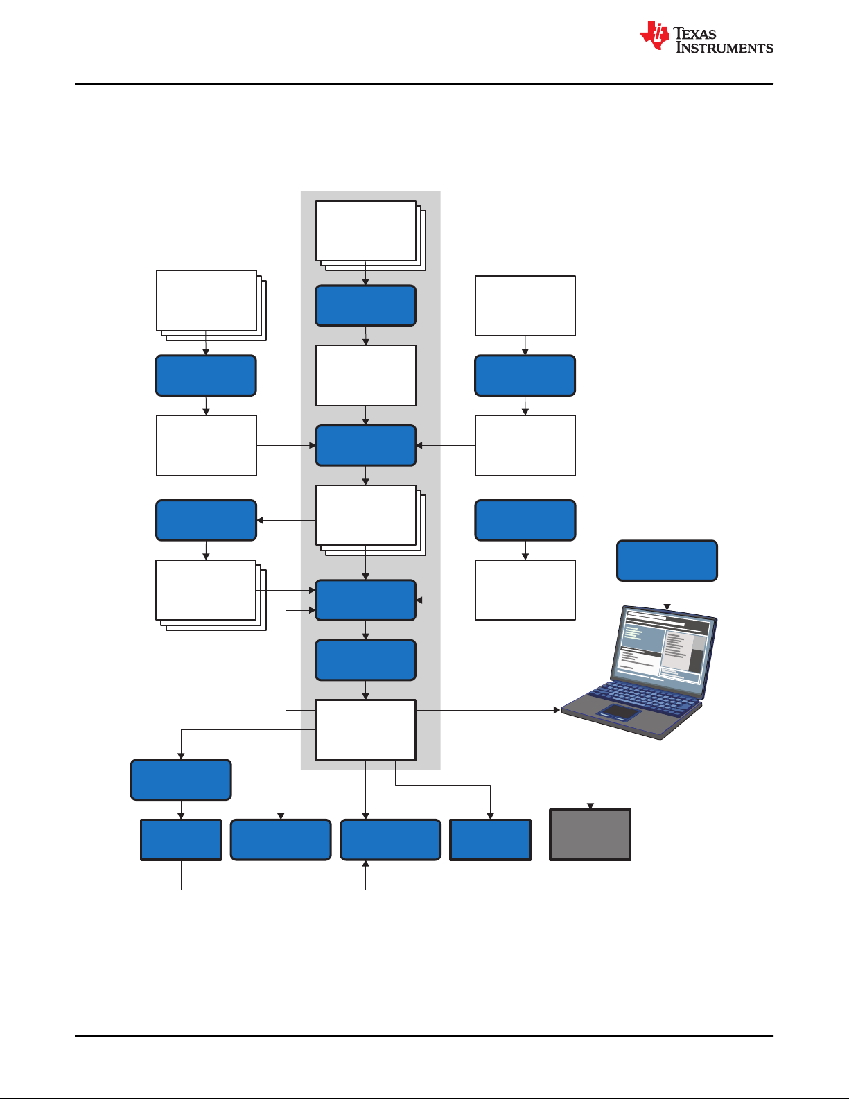
C
source
files
C/C++
compiler
Assembler
source
Assembler
Library-build
utility
Run-time-
support
library
Archiver
Archiver
Macro
library
Linker
C2xx
assembler
source
Transition
assistant
Assembler
source
Macro
source
files
Object
files
Library of
object
files
Executable
object file
Debugging
tools
Absolute lister
Hex-conversion
utility
Cross-reference
lister
Object file
utilities
C28x
EPROM
programmer
Post-link
optimizer
Introduction to the Software Development Tools
www.ti.com
1.1 Software Development Tools Overview
Figure 1-1 shows the TMS320C28x software development flow. The shaded portion highlights the most common
development path; the other portions are optional. The other portions are peripheral functions that enhance the
development process.
16 TMS320C28x Assembly Language Tools
v20.12.0.STS
Figure 1-1. TMS320C28x Software Development Flow
Copyright © 2020 Texas Instruments Incorporated
SPRU513V – JULY 2001 – REVISED DECEMBER 2020
Submit Document Feedback
Page 17

www.ti.com
Introduction to the Software Development Tools
1.2 Tools Descriptions
The following list describes the tools that are shown in Figure 1-1:
• The C/C++ compiler accepts C/C++ source code and produces TMS320C28x machine code object
modules. See the TMS320C28x Optimizing C/C++ Compiler User's Guide for more information. A shell
program, an optimizer, and an interlist utility are included in the installation:
– The shell program enables you to compile, assemble, and link source modules in one step.
– The optimizer modifies code to improve the efficiency of C/C++ programs.
– The interlist utility interlists C/C++ source statements with assembly language output to correlate code
produced by the compiler with your source code.
• The assembler translates assembly language source files into machine language object modules. Source
files can contain instructions, assembler directives, and macro directives. You can use assembler directives
to control the assembly process, including the source listing format, data alignment, and section content. See
Chapter 4 through Chapter 6. See the TMS320C28x DSP CPU and Instruction Set Reference Guide for
detailed information on the assembly language instruction set.
• The linker combines object files into a single executable object module. It performs symbolic relocation and
resolves external references. The linker accepts relocatable object modules (created by the assembler) as
input. It also accepts archiver library members and output modules created by a previous linker run. Link
directives allow you to combine object file sections, bind sections or symbols to addresses or within memory
ranges, and define global symbols. See Chapter 8.
• The archiver allows you to collect a group of files into a single archive file, called a library. The most common
use of the archiver is to collect a group of object files into an object library. The linker extracts object library
members to resolve external references during the link. You can also use the archiver to collect several
macros into a macro library. The assembler searches the library and uses the members that are called as
macros by the source file. The archiver allows you to modify a library by deleting, replacing, extracting, or
adding members. See Section 7.1.
• The library information archiver allows you to create an index library of several object file library variants,
which is useful when several variants of a library with different options are available. Rather than refer to a
specific library, you can link against the index library, and the linker will choose the best match from the
indexed libraries. See Section 7.5 for more information about using the archiver to manage the content of a
library.
• You can use the library-build utility to build your own customized run-time-support library. See the
TMS320C28x Optimizing C/C++ Compiler User's Guide for more information.
• The hex conversion utility converts object files to TI-Tagged, ASCII-Hex, Intel, Motorola-S, or Tektronix
object format. Converted files can be downloaded to an EPROM programmer. See Chapter 12.
• The absolute lister uses linked object files to create .abs files. These files can be assembled to produce a
listing of the absolute addresses of object code. See Chapter 9.
• The cross-reference lister uses object files to produce a cross-reference listing showing symbols, their
definition, and their references in the linked source files. See Chapter 10.
• The main product of this development process is a executable object file that can be executed on a
TMS320C28x device. You can use one of several debugging tools to refine and correct your code. Available
products include:
– An instruction-accurate and clock-accurate software simulator
– An XDS emulator
SPRU513V – JULY 2001 – REVISED DECEMBER 2020
Submit Document Feedback
Copyright © 2020 Texas Instruments Incorporated
TMS320C28x Assembly Language Tools
v20.12.0.STS
17
Page 18

Introduction to the Software Development Tools
www.ti.com
In addition, the following utilities are provided to help examine or manage the content of a given object file:
• The object file display utility prints the contents of object files and object libraries in either human readable
or XML formats. See Section 11.1.
• The disassembler decodes the machine code from object modules to show the assembly instructions that it
represents. See Section 11.2.
• The name utility prints a list of symbol names for objects and functions defined or referenced in an object file
or object archive. See Section 11.3.
• The strip utility removes symbol table and debugging information from object files and object libraries. See
Section 11.4.
18 TMS320C28x Assembly Language Tools
v20.12.0.STS
SPRU513V – JULY 2001 – REVISED DECEMBER 2020
Submit Document Feedback
Copyright © 2020 Texas Instruments Incorporated
Page 19

www.ti.com Introduction to Object Modules
Chapter 2
Introduction to Object Modules
The assembler creates object modules from assembly code, and the linker creates executable object files from
object modules. These executable object files can be executed by a TMS320C28x device.
Object modules make modular programming easier because they encourage you to think in terms of blocks of
code and data when you write an assembly language program. These blocks are known as sections. Both the
assembler and the linker provide directives that allow you to create and manipulate sections.
This chapter focuses on the concept and use of sections in assembly language programs.
2.1 Object File Format Specifications.............................................................................................................................20
2.2 Executable Object Files............................................................................................................................................. 20
2.3 Introduction to Sections............................................................................................................................................ 20
2.4 How the Assembler Handles Sections..................................................................................................................... 21
2.5 How the Linker Handles Sections.............................................................................................................................27
2.6 Symbols.......................................................................................................................................................................29
2.7 Symbolic Relocations................................................................................................................................................ 32
2.8 Loading a Program.....................................................................................................................................................33
SPRU513V – JULY 2001 – REVISED DECEMBER 2020
Submit Document Feedback
Copyright © 2020 Texas Instruments Incorporated
TMS320C28x Assembly Language Tools
v20.12.0.STS
19
Page 20

Introduction to Object Modules www.ti.com
2.1 Object File Format Specifications
The TI Code Generation Tools for C28x support the use of either the COFF ABI or the Embedded Application
Binary Interface (EABI). The ABI used is determined by the --abi command-line option. The default ABI is COFF.
The object file format generated by the tools differs depending on the ABI used:
• COFF: These object files conform to the Common Object File Format (COFF). See the Common Object File
Format Application Report (SPRAAO8) for details on this format.
• EABI: These object files conform to the ELF (Executable and Linking Format) binary format, which is used by
EABI. See the TMS320C28x Optimizing C/C++ Compiler User's Guide (SPRU514) for information on using
the EABI ABI. The complete EABI specifications can be found in the C28x Embedded Application Binary
Interface Application Report (SPRAC71. The ELF object files conform to the December 17, 2003 snapshot of
the System V generic ABI (or gABI). This specification is currently maintained by SCO.
2.2 Executable Object Files
The linker can be used to produce static executable object modules. An executable object module has the same
format as object files that are used as linker input. The sections in an executable object module, however, have
been combined and placed in target memory, and the relocations are all resolved.
To run a program, the data in the executable object module must be transferred, or loaded, into target system
memory. See Chapter 3 for details about loading and running programs.
2.3 Introduction to Sections
The smallest unit of an object file is a section. A section is a block of code or data that occupies contiguous
space in the memory map. Each section of an object file is separate and distinct.
COFF format executable object files contain sections.
ELF format executable object files contain segments. An ELF segment is a meta-section. It represents a
contiguous region of target memory. It is a collection of sections that have the same property, such as writeable
or readable. An ELF loader needs the segment information, but does not need the section information. The ELF
standard allows the linker to omit ELF section information entirely from the executable object file.
Object files usually contain three default sections:
.text section
.data section Usually contains initialized data
.ebss section (for COFF)
.bss section (for EABI)
Contains executable code
Usually reserves space for uninitialized variables
1
Note that the .data section is used mainly for EABI. For COFF, the compiler generates .cinit sections that are
used to initialize the .ebss section. The assembler can be used to place initialized data in the .data section for
both COFF and EABI.
The assembler and linker allow you to create, name, and link other kinds of sections. The .text, .data, and .ebss
or .bss sections are archetypes for how sections are handled.
There are two basic types of sections:
Initialized sections
Uninitialized sections Reserve space in the memory map for uninitialized data. The .ebss or .bss section is uninitialized;
Contain data or code. The .text and .data sections are initialized; user-named sections created with
the .sect assembler directive are also initialized.
user-named sections created with the .usect assembler directive are also uninitialized.
1
Some targets allow content other than text, such as constants, in .text sections.
20 TMS320C28x Assembly Language Tools
v20.12.0.STS
Copyright © 2020 Texas Instruments Incorporated
SPRU513V – JULY 2001 – REVISED DECEMBER 2020
Submit Document Feedback
Page 21
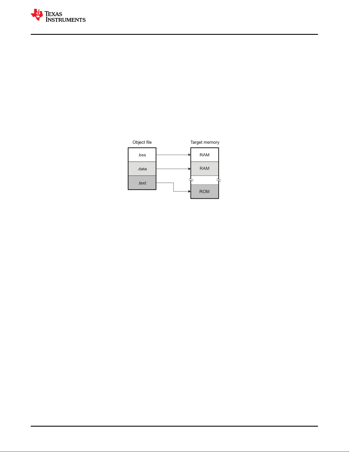
www.ti.com
Introduction to Object Modules
Several assembler directives allow you to associate various portions of code and data with the appropriate
sections. The assembler builds these sections during the assembly process, creating an object file organized as
shown in Figure 2-1.
One of the linker's functions is to relocate sections into the target system's memory map; this function is called
placement. Because most systems contain several types of memory, using sections can help you use target
memory more efficiently. All sections are independently relocatable; you can place any section into any allocated
block of target memory. For example, you can define a section that contains an initialization routine and then
allocate the routine in a portion of the memory map that contains ROM. For information on section placement,
see the "Specifying Where to Allocate Sections in Memory" section of the TMS320C28x Optimizing C/C++
Compiler User's Guide .
Figure 2-1 shows the relationship between sections in an object file and a hypothetical target memory. (This
figure shows COFF sections. For EABI, the .ebss section would be .bss.) ROM may be EEPROM, FLASH or
some other type of physical memory in an actual system.
Figure 2-1. Partitioning Memory Into Logical Blocks
2.3.1 Special Section Names
You can use the .sect and .usect directives to create any section name you like, but certain sections are treated
in a special manner by the linker and the compiler's run-time support library. If you create a section with the
same name as a special section, you should take care to follow the rules for that special section.
A few common special sections are:
• .text -- Used for program code.
• .data -- Used for initialized non-const objects (global variables). (Used mainly with EABI)
• .ebss (COFF) or .bss (EABI) -- Used for uninitialized objects (global variables).
• .econst (COFF) or .const (EABI) -- Used for initialized const objects (string constants, variables declared
const).
• .cinit -- Used to initialize C global variables at startup.
• .stack -- Used for the function call stack.
• .esysmem (COFF) or .sysmem (EABI) - Used for the dynamic memory allocation pool.
For more information on sections, see the "Specifying Where to Allocate Sections in Memory" section of the
TMS320C28x Optimizing C/C++ Compiler User's Guide .
2.4 How the Assembler Handles Sections
The assembler identifies the portions of an assembly language program that belong in a given section. The
assembler has the following directives that support this function:
• .bss
• .data
• .sect
• .text
• .usect
SPRU513V – JULY 2001 – REVISED DECEMBER 2020
Submit Document Feedback
Copyright © 2020 Texas Instruments Incorporated
TMS320C28x Assembly Language Tools
v20.12.0.STS
21
Page 22

Introduction to Object Modules
www.ti.com
The .bss and .usect directives create uninitialized sections; the .text, .data, and .sect directives create initialized
sections.
You can create subsections of any section to give you tighter control of the memory map. Subsections are
created using the .sect and .usect directives. Subsections are identified with the base section name and a
subsection name separated by a colon; see Section 2.4.6.
Note
If you do not use a section directive, the assembler assembles everything into the .text section.
2.4.1 Uninitialized Sections
Uninitialized sections reserve space in TMS320C28x memory; they are usually placed in RAM. These sections
have no actual contents in the object file; they simply reserve memory. A program can use this space at run time
for creating and storing variables.
Uninitialized data areas are built by using the following assembler directives.
• The .bss directive reserves space in the .bss section.
• The .usect directive reserves space in a specific uninitialized user-named section.
Each time you invoke the .bss or .usect directive, the assembler reserves additional space in the .bss or the
user-named section. The syntax is:
.bss symbol , size in words[, blocking flag[, alignment flag] ]
symbol .usect " section name ", size in words[, blocking flag[, alignment flag] ]
symbol points to the first word reserved by this invocation of the .usect directive. The symbol corresponds to the name of
size in words is an absolute expression (see Section 4.9). The .usect directive reserves size in words words in section name. You
blocking flag is an optional parameter. If you specify a value greater than 0 for this parameter, the assembler allocates size in
alignment flag is an optional parameter. It causes the assembler to allocate the specified size in words on long word boundaries.
section name specifies the user-named section in which to reserve space. See Section 2.4.3.
the variable for which you are reserving space. It can be referenced by any other section and can also be declared
as a global symbol (with the .global directive).
must specify a size; there is no default value.
words contiguously. This means the allocated space does not cross a page boundary unless its size is greater than
a page, in which case the allocated space starts a page boundary. By default, the compiler causes this flag to be set
to 0 so that DP load optimization is used. The compiler provides the "blocked" and "noblocked" variable attributes
for controlling blocking on a per-variable basis. For examples of DP load optimization, see the Tools Insider blog in
TI's E2E community.
The resulting alignment will be on a boundary that is 2 to the power of the specified alignment flag. For example, an
alignment flag of 5 gives an alignment of 2**5, which is 32 words.
Initialized section directives (.text, .data, and .sect) change which section is considered the current section (see
Section 2.4.4). However, the .bss and .usect directives do not change the current section; they simply escape
from the current section temporarily. Immediately after a .bss or .usect directive, the assembler resumes
assembling into whatever the current section was before the directive. The .bss and .usect directives can appear
anywhere in an initialized section without affecting its contents. For an example, see Section 2.4.7.
The .usect directive can also be used to create uninitialized subsections. See Section 2.4.6 for more information
on creating subsections.
The .common directive (EABI only) is similar to directives that create uninitialized data sections, except that
common symbols are created by the linker instead.
2.4.2 Initialized Sections
Initialized sections contain executable code or initialized data. The contents of these sections are stored in the
object file and placed in TMS320C28x memory when the program is loaded. Each initialized section is
independently relocatable and may reference symbols that are defined in other sections. The linker automatically
22 TMS320C28x Assembly Language Tools
v20.12.0.STS
Copyright © 2020 Texas Instruments Incorporated
SPRU513V – JULY 2001 – REVISED DECEMBER 2020
Submit Document Feedback
Page 23

www.ti.com
Introduction to Object Modules
resolves these references. The following directives tell the assembler to place code or data into a section. The
syntaxes for these directives are:
.text
.data
.sect " section name "
The .sect directive can also be used to create initialized subsections. See Section 2.4.6, for more information on
creating subsections.
2.4.3 User-Named Sections
User-named sections are sections that you create. You can use them like the default .text, .data, and .ebss
or .bss sections, but each section with a distinct name is kept distinct during assembly.
For example, repeated use of the .text directive builds up a single .text section in the object file. This .text section
is allocated in memory as a single unit. Suppose there is a portion of executable code (perhaps an initialization
routine) that you want the linker to place in a different location than the rest of .text. If you assemble this segment
of code into a user-named section, it is assembled separately from .text, and you can use the linker to allocate it
into memory separately. You can also assemble initialized data that is separate from the .data section, and you
can reserve space for uninitialized variables that is separate from the .ebss or .bss section.
These directives let you create user-named sections:
• The .usect directive creates uninitialized sections that are used like the .ebss or .bss section. These sections
reserve space in RAM for variables.
• The .sect directive creates initialized sections, like the default .text and .data sections, that can contain code
or data. The .sect directive creates user-named sections with relocatable addresses.
The syntaxes for these directives are:
symbol
.usect " section name ", size in words[, blocking flag[, alignment flag ] ]
.sect " section name "
When using COFF, you can create up to 32,767 distinct named sections. When using EABI, the maximum
number of sections is 232-1 (4294967295).
The section name parameter is the name of the section. For the .usect and .sect directives, a section name can
refer to a subsection; see Section 2.4.6 for details.
Each time you invoke one of these directives with a new name, you create a new user-named section. Each time
you invoke one of these directives with a name that was already used, the assembler resumes assembling code
or data (or reserves space) into the section with that name. You cannot use the same names with different
directives. That is, you cannot create a section with the .usect directive and then try to use the same section
with .sect .
2.4.4 Current Section
The assembler adds code or data to one section at a time. The section the assembler is currently filling is the
current section. The .text, .data, and .sect directives change which section is considered the current section.
When the assembler encounters one of these directives, it stops assembling into the current section (acting as
an implied end of current section command). The assembler sets the designated section as the current section
and assembles subsequent code into the designated section until it encounters another .text, .data, or .sect
directive.
If one of these directives sets the current section to a section that already has code or data in it from earlier in
the file, the assembler resumes adding to the end of that section. The assembler generates only one contiguous
section for each given section name. This section is formed by concatenating all of the code or data which was
placed in that section.
SPRU513V – JULY 2001 – REVISED DECEMBER 2020
Submit Document Feedback
Copyright © 2020 Texas Instruments Incorporated
TMS320C28x Assembly Language Tools
v20.12.0.STS
23
Page 24

Introduction to Object Modules
www.ti.com
2.4.5 Section Program Counters
The assembler maintains a separate program counter for each section. These program counters are known as
section program counters, or SPCs.
An SPC represents the current address within a section of code or data. Initially, the assembler sets each SPC
to 0. As the assembler fills a section with code or data, it increments the appropriate SPC. If you resume
assembling into a section, the assembler remembers the appropriate SPC's previous value and continues
incrementing the SPC from that value.
The assembler treats each section as if it began at address 0; the linker relocates the symbols in each section
according to the final address of the section in which that symbol is defined. See Section 2.7 for information on
relocation.
2.4.6 Subsections
A subsection is created by creating a section with a colon in its name. Subsections are logical subdivisions of
larger sections. Subsections are themselves sections and can be manipulated by the assembler and linker.
The assembler has no concept of subsections; to the assembler, the colon in the name is not special. The
subsection .text:rts would be considered completely unrelated to its parent section .text, and the assembler will
not combine subsections with their parent sections.
Subsections are used to keep parts of a section as distinct sections so that they can be separately manipulated.
For instance, by placing each function and object in a uniquely-named subsection, the linker gets a finer-grained
view of the section for memory placement and unused-function elimination.
By default, when the linker sees a SECTION directive in the linker command file like ".text", it will gather .text
and all subsections of .text into one large output section named ".text". You can instead use the SECTION
directive to control the subsection independently. See Section 8.5.5.1 for an example.
You can create subsections in the same way you create other user-named sections: by using the .sect or .usect
directive.
The syntaxes for a subsection name are:
symbol
.usect " section_name : subsection_name ", size in words[, blocking flag[, alignment flag] ]
.sect " section_name : subsection_name "
A subsection is identified by the base section name followed by a colon and the name of the subsection. The
subsection name may not contain any spaces.
A subsection can be allocated separately or grouped with other sections using the same base name. For
example, you create a subsection called _func within the .text section:
.sect ".text:_func"
Using the linker's SECTIONS directive, you can allocate .text:_func separately, or with all the .text sections.
You can create two types of subsections:
• Initialized subsections are created using the .sect directive. See Section 2.4.2.
• Uninitialized subsections are created using the .usect directive. See Section 2.4.1.
Subsections are placed in the same manner as sections. See Section 8.5.5 for information on the SECTIONS
directive.
24 TMS320C28x Assembly Language Tools
v20.12.0.STS
SPRU513V – JULY 2001 – REVISED DECEMBER 2020
Submit Document Feedback
Copyright © 2020 Texas Instruments Incorporated
Page 25

www.ti.com
Introduction to Object Modules
2.4.7 Using Sections Directives
Figure 2-2 shows how you can build sections incrementally, using the sections directives to swap back and forth
between the different sections. You can use sections directives to begin assembling into a section for the first
time, or to continue assembling into a section that already contains code. In the latter case, the assembler simply
appends the new code to the code that is already in the section.
The format in Figure 2-2 is a listing file. Figure 2-2 shows how the SPCs are modified during assembly. A line in
a listing file has four fields:
Field 1 contains the source code line counter.
Field 2 contains the section program counter.
Field 3 contains the object code.
Field 4 contains the original source statement.
See Section 4.12 for more information on interpreting the fields in a source listing.
SPRU513V – JULY 2001 – REVISED DECEMBER 2020
Submit Document Feedback
Copyright © 2020 Texas Instruments Incorporated
TMS320C28x Assembly Language Tools
v20.12.0.STS
25
Page 26
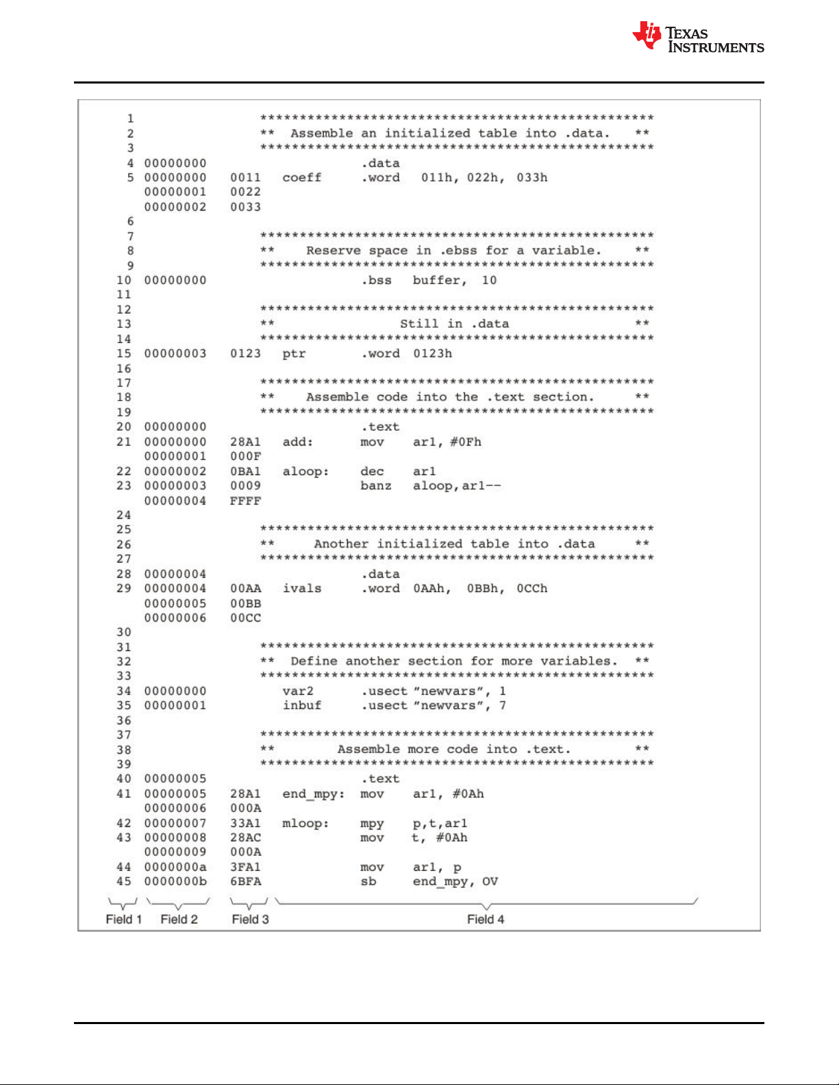
Introduction to Object Modules
www.ti.com
Figure 2-2. Using Sections Directives Example
26 TMS320C28x Assembly Language Tools
v20.12.0.STS
SPRU513V – JULY 2001 – REVISED DECEMBER 2020
Submit Document Feedback
Copyright © 2020 Texas Instruments Incorporated
Page 27
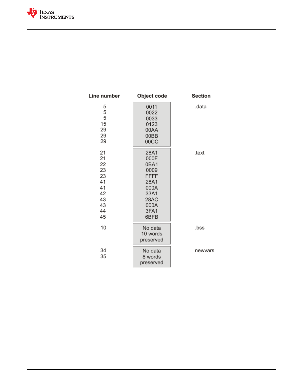
www.ti.com
Introduction to Object Modules
As Figure 2-3 shows, the example code in Figure 2-2 creates four sections:
.text contains twelve 16-bit words of object code.
.data contains seven 16-bit words of initialized data.
.bss reserves ten 16-bit words in memory.
newvars is a user-named section created with the .usect directive; it contains eight 16-bit words in memory.
The second column shows the object code that is assembled into these sections; the first column shows the
source statements that generated the object code.
Figure 2-3. Object Code Generated by the File in Figure 2-2
2.5 How the Linker Handles Sections
The linker has two main functions related to sections. First, the linker uses the sections in object files as building
blocks; it combines input sections to create output sections in an executable output module. Second, the linker
chooses memory addresses for the output sections; this is called placement. Two linker directives support these
functions:
• The MEMORY directive allows you to define the memory map of a target system. You can name portions of
memory and specify their starting addresses and their lengths.
• The SECTIONS directive tells the linker how to combine input sections into output sections and where to
place these output sections in memory.
SPRU513V – JULY 2001 – REVISED DECEMBER 2020
Submit Document Feedback
Copyright © 2020 Texas Instruments Incorporated
TMS320C28x Assembly Language Tools
v20.12.0.STS
27
Page 28
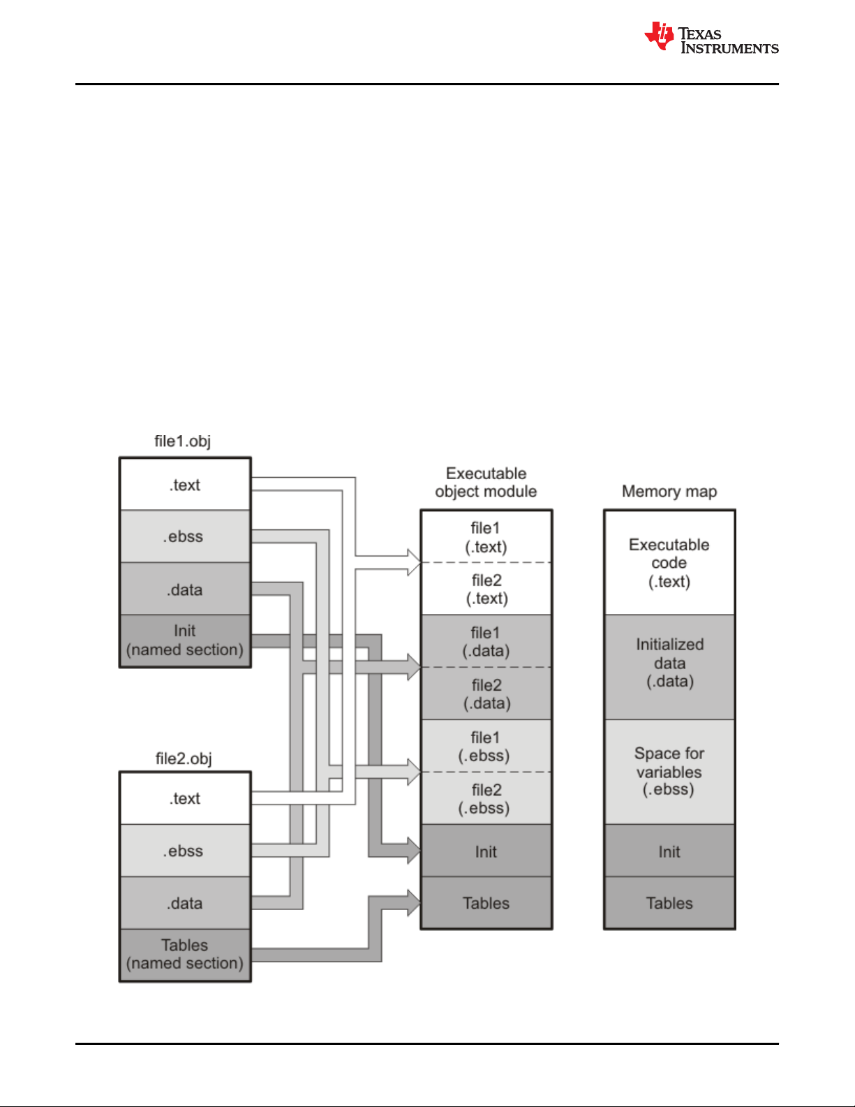
Introduction to Object Modules
www.ti.com
Subsections let you manipulate the placement of sections with greater precision. You can specify the location of
each subsection with the linker's SECTIONS directive. If you do not specify a subsection, the subsection is
combined with the other sections with the same base section name. See Section 8.5.5.1.
It is not always necessary to use linker directives. If you do not use them, the linker uses the target processor's
default placement algorithm described in Section 8.7. When you do use linker directives, you must specify them
in a linker command file.
Refer to the following sections for more information about linker command files and linker directives:
• Section 8.5, Linker Command Files
• Section 8.5.4, The MEMORY Directive
• Section 8.5.5, The SECTIONS Directive
• Section 8.7, Default Placement Algorithm
2.5.1 Combining Input Sections
Figure 2-4 provides a simplified example of the process of linking two files together.
Note that this is a simplified example, so it does not show all the sections that will be created or the actual
sequence of the sections. See Section 8.7 for the actual default memory placement map for TMS320C28x. (The
following figure shows sections used by COFF. For EABI, change the .ebss section to .bss.)
Figure 2-4. Combining Input Sections to Form an Executable Object Module
28 TMS320C28x Assembly Language Tools
v20.12.0.STS
SPRU513V – JULY 2001 – REVISED DECEMBER 2020
Submit Document Feedback
Copyright © 2020 Texas Instruments Incorporated
Page 29

www.ti.com
Introduction to Object Modules
In Figure 2-4, file1.obj and file2.obj have been assembled to be used as linker input. Each contains
the .text, .data, and .ebss default sections; in addition, each contains a user-named section. The executable
object module shows the combined sections. The linker combines the .text section from file1.obj and the .text
section from file2.obj to form one .text section, then combines the two .data sections and the two .ebss sections,
and finally places the user-named sections at the end. The memory map shows the combined sections to be
placed into memory.
2.5.2 Placing Sections
Figure 2-4 illustrates the linker's default method for combining sections. Sometimes you may not want to use the
default setup. For example, you may not want all of the .text sections to be combined into a single .text section.
Or you may want a user-named section placed where the .data section would normally be allocated. Most
memory maps contain various types of memory (RAM, ROM, EEPROM, FLASH, etc.) in varying amounts; you
may want to place a section in a specific type of memory.
For further explanation of section placement within the memory map, see the discussions in Section 8.5.4 and
Section 8.5.5. See Section 8.7 for the actual default memory allocation map for TMS320C28x.
2.6 Symbols
An object file contains a symbol table that stores information about symbols in the object file. The linker uses this
table when it performs relocation. See Section 2.7.
An object file symbol is a named 32-bit integer value, usually representing an address. A symbol can represent
such things as the starting address of a function, variable, section, or an absolute integer (such as the size of the
stack).
Symbols are defined in assembly by adding a label or a directive such as .set .equ .bss, or .usect.
Symbols have a binding, which is similar to the C concept of linkage. Both COFF and ELF file formats may
contain symbols bound locally and globally. ELF also binds symbols as weak symbols.
• Global symbols are visible to the entire program. The linker does not allow more than one global definition
of a particular symbol; it issues a multiple-definition error if a global symbol is defined more than once. (The
assembler can provide a similar multiple-definition error for local symbols.) A reference to a global symbol
from any object file refers to the one and only allowed global definition of that symbol. Assembly code must
explicitly make a symbol global by adding a .def, .ref, or .global directive. (See Section 2.6.1.)
• Local symbols are visible only within one object file; each object file that uses a symbol needs its own local
definition. References to local symbols in an object file are entirely unrelated to local symbols of the same
name in another object file. By default, a symbol is local. (See Section 2.6.2.)
• Weak symbols (EABI only) are symbols that may be used but not defined in the current module. They may
or may not be defined in another module. A weak symbol is intended to be overridden by a strong (non-weak)
global symbol definition of the same name in another object file. If a strong definition is available, the weak
symbol is replaced by the strong symbol. If no definition is available (that is, if the weak symbol is
unresolved), no error is generated, but the weak variable's address is considered to be null (0). For this
reason, application code that accesses a weak variable must check that its address is not zero before
attempting to access the variable. (See Section 2.6.3.)
Absolute symbols are symbols that have a numeric value. They may be constants. To the linker, such symbols
are unsigned values, but the integer may be treated as signed or unsigned depending on how it is used. The
range of legal values for an absolute integer is 0 to 2^32-1 for unsigned treatment and -2^31 to 2^31-1 for signed
treatment.
In general, common symbols (see .common directive) are preferred over weak symbols.
See Section 4.8 for information about assembler symbols.
SPRU513V – JULY 2001 – REVISED DECEMBER 2020
Submit Document Feedback
Copyright © 2020 Texas Instruments Incorporated
TMS320C28x Assembly Language Tools
v20.12.0.STS
29
Page 30

Introduction to Object Modules
www.ti.com
2.6.1 Global (External) Symbols
Global symbols are symbols that are either accessed in the current module but defined in another (an external
symbol) or defined in the current module and accessed in another. Such symbols are visible across object
modules. You must use the .def, .ref, or .global directive to identify a symbol as external:
.def The symbol is defined in the current file and may be used in another file.
.ref The symbol is referenced in the current file, but defined in another file.
.global The symbol can be either of the above. The assembler chooses either .def or .ref as appropriate for each symbol.
The following code fragment illustrates these definitions.
.def x
.ref y
.global z
.global q
x: ADD AR1, #56h
B y, UNC
q: ADD AR1, #56h
B z, UNC
In this example, the .def definition of x says that it is an external symbol defined in this file and that other files
can reference x. The .ref definition of y says that it is an undefined symbol that is defined in another file.
The .global definition of z says that it is defined in some file and available in this file. The .global definition of q
says that it is defined in this file and that other files can reference q.
The assembler places x, y, z, and q in the object file's symbol table. When the file is linked with other object files,
the entries for x and q resolve references to x and q in other files. The entries for y and z cause the linker to look
through the symbol tables of other files for y's and z's definitions.
The linker attempts to match all references with corresponding definitions. If the linker cannot find a symbol's
definition, it prints an error message about the unresolved reference. This type of error prevents the linker from
creating an executable object module.
An error also occurs if the same symbol is defined more than once.
2.6.2 Local Symbols
Local symbols are visible within a single object file. Each object file may have its own local definition for a
particular symbol. References to local symbols in an object file are entirely unrelated to local symbols of the
same name in another object file.
By default, a symbol is local.
2.6.3 Weak Symbols
Weak symbols are symbols that may or may not be defined.
Note
Weak symbols are supported only in EABI mode.
The linker processes symbols that are defined with a "weak" binding differently from symbols that are defined
with global binding. Instead of including a weak symbol in the object file's symbol table (as it would for a global
symbol), the linker only includes a weak symbol in the output of a "final" link if the symbol is required to resolve
an otherwise unresolved reference.
This allows the linker to minimize the number of symbols it includes in the output file's symbol table by omitting
those that are not needed to resolve references. Reducing the size of the output file's symbol table reduces the
time required to link, especially if there are a large number of pre-loaded symbols to link against. This feature is
particularly helpful for OpenCL applications.
30 TMS320C28x Assembly Language Tools
v20.12.0.STS
Copyright © 2020 Texas Instruments Incorporated
SPRU513V – JULY 2001 – REVISED DECEMBER 2020
Submit Document Feedback
Page 31

www.ti.com
Introduction to Object Modules
You can define a weak symbol using either the .weak assembly directive or the weak operator in the linker
command file.
• Using Assembly: To define a weak symbol in an input object file, the source file can be written in assembly.
Use the .weak and .set directives in combination as shown in the following example, which defines a weak
symbol "ext_addr_sym":
.weak ext_addr_sym
ext_addr_sym .set 0x12345678
Assemble the source file that defines weak symbols, and include the resulting object file in the link. The
"ext_addr_sym" in this example is available as a weak symbol in a final link. It is a candidate for removal if
the symbol is not referenced elsewhere in the application. See .weak directive.
• Using the Linker Command File: To define a weak symbol in a linker command file, use the "weak"
operator in an assignment expression to designate that the symbol as eligible for removal from the output
file's symbol table if it is not referenced. In a linker command file, an assignment expression outside a
MEMORY or SECTIONS directive can be used to define a weak linker-defined symbol. For example, you can
define "ext_addr_sym" as follows:
weak(ext_addr_sym) = 0x12345678;
If the linker command file is used to perform the final link, then "ext_addr_sym" is presented to the linker as a
weak symbol; it will not be included in the resulting output file if the symbol is not referenced. See Section
8.6.2.
• Using C/C++ code: See information about the WEAK pragma and weak GCC-style variable attribute in the
TMS320C28x Optimizing C/C++ Compiler User's Guide.
If there are multiple definitions of the same symbol, the linker uses certain rules to determine which definition
takes precedence. Some definitions may have weak binding and others may have strong binding. "Strong" in this
context means that the symbol has not been given a weak binding by either of the two methods described
above. Some definitions may come from an input object file (that is, using assembly directives) and others may
come from an assignment statement in a linker command file.
The linker uses the following guidelines to determine which definition is used when resolving references to a
symbol:
• A strongly bound symbol always takes precedence over a weakly bound symbol.
• If two symbols are both strongly bound or both weakly bound, a symbol defined in a linker command file
takes precedence over a symbol defined in an input object file.
• If two symbols are both strongly bound and both are defined in an input object file, the linker provides a
symbol redefinition error and halts the link process.
2.6.4 The Symbol Table
The assembler generates entries with global (external) binding in the symbol table for each of the following:
• Each .ref, .def, or .global directive (see Section 2.6.1)
• The beginning of each section
The assembler generates entries with local binding for each locally-available function.
For informational purposes, there are also entries in the symbol table for each symbol in a program.
SPRU513V – JULY 2001 – REVISED DECEMBER 2020
Submit Document Feedback
Copyright © 2020 Texas Instruments Incorporated
TMS320C28x Assembly Language Tools
v20.12.0.STS
31
Page 32

Introduction to Object Modules
www.ti.com
2.7 Symbolic Relocations
The assembler treats each section as if it began at address 0. Of course, all sections cannot actually begin at
address 0 in memory, so the linker must relocate sections. For COFF, all relocations are relative to address 0 in
their sections. For EABI, relocations are symbol-relative rather than section-relative.
The linker can relocate sections by:
• Allocating them into the memory map so that they begin at the appropriate address as defined with the
linker's MEMORY directive
• Adjusting symbol values to correspond to the new section addresses
• Adjusting references to relocated symbols to reflect the adjusted symbol values
The linker uses relocation entries to adjust references to symbol values. The assembler creates a relocation
entry each time a relocatable symbol is referenced. The linker then uses these entries to patch the references
after the symbols are relocated. The following example contains a code fragment for a TMS320C28x device for
which the assembler generates relocation entries.
1 .global X
2 00000000 .text
3 00000000 0080' LC Y ; Generates a relocation entry
00000001 0004
4 00000002 28A1! MOV AR1,#X ; Generates a relocation entry
00000003 0000
5 00000004 7621 Y: IDLE
2.7.1 Expressions With Multiple Relocatable Symbols (COFF Only)
Sometimes an expression contains more than one relocatable symbol, or cannot be evaluated at assembly time.
In this case, the assembler encodes the entire expression in the object file. After determining the addresses of
the symbols, the linker computes the value of the expression.
Note
Expression Cannot Be Larger Than Space Reserved
If the value of an expression is larger, in bits, than the space reserved for it, you will receive an error
message from the linker.
Each section in an object module has a table of relocation entries. The table contains one relocation entry for
each relocatable reference in the section. The linker usually removes relocation entries after it uses them. This
prevents the output file from being relocated again (if it is relinked or when it is loaded). A file that contains no
relocation entries is an absolute file (all its addresses are absolute addresses, which are addresses known at
assembly time). If you want the linker to retain relocation entries, invoke the linker with the --relocatable option
(see Section 8.4.3.2).
In the example in Section 2.7, both symbols X and Y are relocatable. Y is defined in the .text section of this
module; X is defined in another module. When the code is assembled, X has a value of 0 (the assembler
assumes all undefined external symbols have values of 0), and Y has a value of 4 (relative to address 0 in
the .text section). The assembler generates two relocation entries: one for X and one for Y. The reference to X is
an external reference (indicated by the ! character in the listing). The reference to Y is to an internally defined
relocatable symbol (indicated by the ' character in the listing).
32 TMS320C28x Assembly Language Tools
v20.12.0.STS
SPRU513V – JULY 2001 – REVISED DECEMBER 2020
Submit Document Feedback
Copyright © 2020 Texas Instruments Incorporated
Page 33

www.ti.com
Introduction to Object Modules
After the code is linked, suppose that X is relocated to address 0x7100. Suppose also that the .text section is
relocated to begin at address 0x7200; Y now has a relocated value of 0x7204. The linker uses the two relocation
entries to patch the two references in the object code:
0080' LC Y
0004 7204
28A1! MOV AR1,#X
0000 7100
becomes
becomes
0080'
28A1!
Sometimes an expression contains more than one relocatable symbol, or cannot be evaluated at assembly time.
In this case, the assembler encodes the entire expression in the object file. After determining the addresses of
the symbols, the linker computes the value of the expression as shown in the following example.
1 .global sym1, sym2
2
3 00000000 FF20% MOV ACC, #(sym2-sym1)
00000001 0000
The symbols sym1 and sym2 are both externally defined. Therefore, the assembler cannot evaluate the
expression sym2 - sym1, so it encodes the expression in the object file. The '%' listing character indicates a
relocation expression. Suppose the linker relocates sym2 to 300h and sym1 to 200h. Then the linker computes
the value of the expression to be 300h - 200h = 100h. Thus the MOV instruction is patched to:
00000000 FF20 MOV ACC, #(sym2-sym1)
00000001 0100
2.8 Loading a Program
The linker creates an executable object file which can be loaded in several ways, depending on your execution
environment. These methods include using Code Composer Studio or the hex conversion utility. For details, see
Section 3.1.
SPRU513V – JULY 2001 – REVISED DECEMBER 2020
Submit Document Feedback
Copyright © 2020 Texas Instruments Incorporated
TMS320C28x Assembly Language Tools
v20.12.0.STS
33
Page 34

Introduction to Object Modules www.ti.com
This page intentionally left blank.
34 TMS320C28x Assembly Language Tools
v20.12.0.STS
SPRU513V – JULY 2001 – REVISED DECEMBER 2020
Submit Document Feedback
Copyright © 2020 Texas Instruments Incorporated
Page 35

www.ti.com Program Loading and Running
Chapter 3
Program Loading and Running
Even after a program is written, compiled, and linked into an executable object file, there are still many tasks that
need to be performed before the program does its job. The program must be loaded onto the target, memory
and registers must be initialized, and the program must be set to running.
Some of these tasks need to be built into the program itself. Bootstrapping is the process of a program
performing some of its own initialization. Many of the necessary tasks are handled for you by the compiler and
linker, but if you need more control over these tasks, it helps to understand how the pieces are expected to fit
together.
This chapter will introduce you to the concepts involved in program loading, initialization, and startup.
This chapter does not cover dynamic loading.
This chapter currently provides examples for the C6000 device family. Refer to your device documentation for
various device-specific aspects of bootstrapping.
3.1 Loading........................................................................................................................................................................36
3.2 Entry Point...................................................................................................................................................................40
3.3 Run-Time Initialization............................................................................................................................................... 41
3.4 Arguments to main.....................................................................................................................................................44
3.5 Run-Time Relocation..................................................................................................................................................44
3.6 Additional Information............................................................................................................................................... 44
SPRU513V – JULY 2001 – REVISED DECEMBER 2020
Submit Document Feedback
Copyright © 2020 Texas Instruments Incorporated
TMS320C28x Assembly Language Tools
v20.12.0.STS
35
Page 36

Program Loading and Running
www.ti.com
3.1 Loading
A program needs to be placed into the target device's memory before it may be executed. Loading is the
process of preparing a program for execution by initializing device memory with the program's code and data. A
loader might be another program on the device, an external agent (for example, a debugger), or the device
might initialize itself after power-on, which is known as bootstrap loading, or bootloading.
The loader is responsible for constructing the load image in memory before the program starts. The load image
is the program's code and data in memory before execution. What exactly constitutes loading depends on the
environment, such as whether an operating system is present. This section describes several loading schemes
for bare-metal devices. This section is not exhaustive. Additionally, with the COFF RAM model, the loader is
responsible for parsing the .cinit section and performing the initializations encoded therein at load time.
A program may be loaded in the following ways:
• A debugger running on a connected host workstation. In a typical embedded development setup, the
device is subordinate to a host running a debugger such as Code Composer Studio (CCS). The device is
connected with a communication channel such as a JTAG interface. CCS reads the program and writes the
load image directly to target memory through the communications interface.
• "Burning" the load image onto an EPROM module. The hex converter (hex2000) can assist with this by
converting the executable object file into a format suitable for input to an EPROM programmer. The EPROM
is placed onto the device itself and becomes a part of the device's memory. See Chapter 12 for details.
• Bootstrap loading from a dedicated peripheral, such as an I2C peripheral. The device may require a
small program called a bootloader to perform the loading from the peripheral. The hex converter can assist in
creating a bootloader.
• Another program running on the device. The running program can create the load image and transfer
control to the loaded program. If an operating system is present, it may have the ability to load and run
programs.
3.1.1 Load and Run Addresses
Consider an embedded device for which the program's load image is burned onto EPROM/ROM. Variable data
in the program must be writable, and so must be located in writable memory, typically RAM. However, RAM is
volatile, meaning it will lose its contents when the power goes out. If this data must have an initial value, that
initial value must be stored somewhere else in the load image, or it would be lost when power is cycled. The
initial value must be copied from the non-volatile ROM to its run-time location in RAM before it is used. See
Section 8.8 for ways this is done.
The load address is the location of an object in the load image.
The run address is the location of the object as it exists during program execution.
An object is a chunk of memory. It represents a section, segment, function, or data.
The load and run addresses for an object may be the same. This is commonly the case for program code and
read-only data, such as the .econst section. In this case, the program can read the data directly from the load
address. Sections that have no initial value, such as the .ebss section, do not have load data and are considered
to have load and run addresses that are the same. If you specify different load and run addresses for an
uninitialized section, the linker provides a warning and ignores the load address.
The load and run addresses for an object may be different. This is commonly the case for writable data, such as
the .data section. The .data section's starting contents are placed in ROM and copied to RAM. This often occurs
during program startup, but depending on the needs of the object, it may be deferred to sometime later in the
program as described in Section 3.5.
Symbols in assembly code and object files almost always refer to the run address. When you look at an address
in the program, you are almost always looking at the run address. The load address is rarely used for anything
but initialization.
The load and run addresses for a section are controlled by the linker command file and are recorded in the
object file metadata.
36 TMS320C28x Assembly Language Tools
v20.12.0.STS
Copyright © 2020 Texas Instruments Incorporated
SPRU513V – JULY 2001 – REVISED DECEMBER 2020
Submit Document Feedback
Page 37

www.ti.com
Program Loading and Running
The load address determines where a loader places the raw data for the section. Any references to the section
(such as references to labels in it) refer to its run address. The application must copy the section from its load
address to its run address before the first reference of the symbol is encountered at run time; this does not
happen automatically simply because you specify a separate run address. For examples that specify load and
run addresses, see Section 8.5.6.1.
For an example that illustrates how to move a block of code at run time, see Moving a Function from Slow to
Fast Memory at Run Time. To create a symbol that lets you refer to the load-time address, rather than the run-
time address, see the .label directive. To use copy tables to copy objects from load-space to run-space at boot
time, see Section 8.8.
ELF format executable object files contain segments. See Section 2.3 for information about sections and
segments. COFF format executable object files contain sections.
3.1.2 Bootstrap Loading
The details of bootstrap loading (bootloading) vary a great deal between devices. Not every device supports
every bootloading mode, and using the bootloader is optional. This section discusses various bootloading
schemes to help you understand how they work. Refer to your device's data sheet to see which bootloading
schemes are available and how to use them.
A typical embedded system uses bootloading to initialize the device. The program code and data may be stored
in ROM or FLASH memory. At power-on, an on-chip bootloader (the primary bootloader) built into the device
hardware starts automatically.
Figure 3-1. Bootloading Sequence (Simplified)
The primary bootloader is typically very small and copies a limited amount of memory from a dedicated location
in ROM to a dedicated location in RAM. (Some bootloaders support copying the program from an I/O peripheral.)
After the copy is completed, it transfers control to the program.
For many programs, the primary bootloader is not capable of loading the entire program, so these programs
supply a more capable secondary bootloader. The primary bootloader loads the secondary bootloader and
transfers control to it. Then, the secondary bootloader loads the rest of the program and transfers control to it.
There can be any number of layers of bootloaders, each loading a more capable bootloader to which it transfers
control.
SPRU513V – JULY 2001 – REVISED DECEMBER 2020
Submit Document Feedback
Copyright © 2020 Texas Instruments Incorporated
TMS320C28x Assembly Language Tools
v20.12.0.STS
37
Page 38

Program Loading and Running
www.ti.com
Figure 3-2. Bootloading Sequence with Secondary Bootloader
3.1.2.1 Boot, Load, and Run Addresses
The boot address of a bootloaded object is where its raw data exists in ROM before power-on.
The boot, load, and run addresses for an object may all be the same; this is commonly the case for .const data.
If they are different, the object's contents must be copied to the correct location before the object may be used.
The boot address may be different than the load address. The bootloader is responsible for copying the raw data
to the load address.
The boot address is not controlled by the linker command file or recorded in the object file; it is strictly a
convention shared by the bootloader and the program.
3.1.2.2 Primary Bootloader
The detailed operation of the primary bootloader is device-specific. Some devices have complex capabilities
such as booting from an I/O peripheral or configuring memory controller parameters.
3.1.2.3 Secondary Bootloader
The hex converter assumes the secondary bootloader is of a particular format. The hex converter's model
bootloader uses a boot table. You can use whatever format you want, but if you follow this model, the hex
converter can create the boot table automatically.
3.1.2.4 Boot Table
The input for the model secondary bootloader is the boot table. The boot table contains records that instruct the
secondary bootloader to copy blocks of data contained in the table to specified destination addresses. The hex
conversion utility automatically builds the boot table for the secondary bootloader. Using the utility, you specify
the sections you want to initialize, the boot table location, and the name of the section containing the secondary
bootloader routine and where it should be located. The hex conversion utility builds a complete image of the
table and adds it to the program.
38 TMS320C28x Assembly Language Tools
v20.12.0.STS
SPRU513V – JULY 2001 – REVISED DECEMBER 2020
Submit Document Feedback
Copyright © 2020 Texas Instruments Incorporated
Page 39

www.ti.com
Program Loading and Running
The boot table is target-specific. For C6000, the format of the boot table is simple. A header record contains a 4byte field that indicates where the boot loader should branch after it has completed copying data. After the
header, each section that is to be included in the boot table has the following contents:
• 4-byte field containing the size of the section
• 4-byte field containing the destination address for the copy
• the raw data
• 0 to 3 bytes of trailing padding to make the next field aligned to 4 bytes
More than one section can be entered; a termination block containing an all-zero 4-byte field follows the last
section.
See Section 12.11.2 for details about the boot table format.
3.1.2.5 Bootloader Routine
The bootloader routine is a normal function, except that it executes before the C environment is set up. For this
reason, it can't use the C stack, and it can't call any functions that have yet to be loaded!
The following sample code is for C6000 and is from Creating a Second-Level Bootloader for FLASH Bootloading
on TMS320C6000 Platform With Code Composer Studio (SPRA999).
Example 3-1. Sample Secondary Bootloader Routine
; ======== boot_c671x.s62 ========
; global EMIF symbols defined for the c671x family
.include boot_c671x.h62
.sect ".boot_load"
.global _boot
_boot:
;************************************************************************
;* DEBUG LOOP − COMMENT OUT B FOR NORMAL OPERATION
;************************************************************************
zero B1
_myloop: ; [!B1] B _myloop
nop 5
_myloopend: nop
;************************************************************************
;* CONFIGURE EMIF
;************************************************************************
;****************************************************************
; *EMIF_GCTL = EMIF_GCTL_V;
;****************************************************************
mvkl EMIF_GCTL,A4
|| mvkl EMIF_GCTL_V,B4
mvkh EMIF_GCTL,A4
|| mvkh EMIF_GCTL_V,B4
stw B4,*A4
;****************************************************************
; *EMIF_CE0 = EMIF_CE0_V
;****************************************************************
mvkl EMIF_CE0,A4
|| mvkl EMIF_CE0_V,B4
mvkh EMIF_CE0,A4
|| mvkh EMIF_CE0_V,B4
stw B4,*A4
;****************************************************************
; *EMIF_CE1 = EMIF_CE1_V (setup for 8−bit async)
;****************************************************************
mvkl EMIF_CE1,A4
|| mvkl EMIF_CE1_V,B4
mvkh EMIF_CE1,A4
|| mvkh EMIF_CE1_V,B4
stw B4,*A4
;****************************************************************
; *EMIF_CE2 = EMIF_CE2_V (setup for 32−bit async)
;****************************************************************
mvkl EMIF_CE2,A4
|| mvkl EMIF_CE2_V,B4
SPRU513V – JULY 2001 – REVISED DECEMBER 2020
Submit Document Feedback
Copyright © 2020 Texas Instruments Incorporated
TMS320C28x Assembly Language Tools
v20.12.0.STS
39
Page 40

Program Loading and Running
mvkh EMIF_CE2,A4
|| mvkh EMIF_CE2_V,B4
stw B4,*A4
;****************************************************************
; *EMIF_CE3 = EMIF_CE3_V (setup for 32−bit async)
;****************************************************************
|| mvkl EMIF_CE3,A4
|| mvkl EMIF_CE3_V,B4 ;
mvkh EMIF_CE3,A4
|| mvkh EMIF_CE3_V,B4
stw B4,*A4
;****************************************************************
; *EMIF_SDRAMCTL = EMIF_SDRAMCTL_V
;****************************************************************
|| mvkl EMIF_SDRAMCTL,A4
|| mvkl EMIF_SDRAMCTL_V,B4 ;
mvkh EMIF_SDRAMCTL,A4
|| mvkh EMIF_SDRAMCTL_V,B4
stw B4,*A4
;****************************************************************
; *EMIF_SDRAMTIM = EMIF_SDRAMTIM_V
;****************************************************************
|| mvkl EMIF_SDRAMTIM,A4
|| mvkl EMIF_SDRAMTIM_V,B4 ;
mvkh EMIF_SDRAMTIM,A4
|| mvkh EMIF_SDRAMTIM_V,B4
stw B4,*A4
;****************************************************************
; *EMIF_SDRAMEXT = EMIF_SDRAMEXT_V
;****************************************************************
|| mvkl EMIF_SDRAMEXT,A4
|| mvkl EMIF_SDRAMEXT_V,B4 ;
mvkh EMIF_SDRAMEXT,A4
|| mvkh EMIF_SDRAMEXT_V,B4
stw B4,*A4
;****************************************************************************
; copy sections
;****************************************************************************
mvkl COPY_TABLE, a3 ; load table pointer
mvkh COPY_TABLE, a3
ldw *a3++, b1 ; Load entry point
copy_section_top:
ldw *a3++, b0 ; byte count
ldw *a3++, a4 ; ram start address
nop 3
[!b0] b copy_done ; have we copied all sections?
nop 5
copy_loop:
ldb *a3++,b5
sub b0,1,b0 ; decrement counter
[ b0] b copy_loop ; setup branch if not done
[!b0] b copy_section_top
zero a1
[!b0] and 3,a3,a1
stb b5,*a4++
[!b0] and −4,a3,a5 ; round address up to next multiple of 4
[ a1] add 4,a5,a3 ; round address up to next multiple of 4
;****************************************************************************
; jump to entry point
;****************************************************************************
copy_done:
b .S2 b1
nop 5
www.ti.com
3.2 Entry Point
The entry point is the address at which the execution of the program begins. This is the address of the startup
routine. The startup routine is responsible for initializing and calling the rest of the program. For a C/C++
program, the startup routine is usually named _c_int00 (see Section 3.3.1). After the program is loaded, the
value of the entry point is placed in the PC register and the CPU is allowed to run.
40 TMS320C28x Assembly Language Tools
v20.12.0.STS
Copyright © 2020 Texas Instruments Incorporated
SPRU513V – JULY 2001 – REVISED DECEMBER 2020
Submit Document Feedback
Page 41

www.ti.com
Program Loading and Running
The object file has an entry point field. For a C/C++ program, the linker will fill in _c_int00 by default. You can
select a custom entry point; see Section 8.4.13. The device itself cannot read the entry point field from the object
file, so it has to be encoded in the program somewhere.
• If you are using a bootloader, the boot table includes an entry point field. When it finishes running, the
bootloader branches to the entry point.
• If you are using an interrupt vector, the entry point is installed as the RESET interrupt handler. When RESET
is applied, the startup routine will be invoked.
• If you are using a hosted debugger, such as CCS, the debugger may explicitly set the program counter (PC)
to the value of the entry point.
3.3 Run-Time Initialization
After the load image is in place, the program can run. The subsections that follow describe bootstrap initialization
of a C/C++ program. An assembly-only program may not need to perform all of these steps.
3.3.1 The _c_int00 Function
The function _c_int00 is the startup routine (also called the boot routine) for C/C++ programs. It performs all the
steps necessary for a C/C++ program to initialize itself.
The name _c_int00 means that it is the interrupt handler for interrupt number 0, RESET, and that it sets up the C
environment. Its name need not be exactly _c_int00, but the linker sets _c_int00 as the entry point for C
programs by default. The compiler's run-time-support library provides a default implementation of _c_int00.
The startup routine is responsible for performing the following actions:
1. Set up status and configuration registers
2. Set up the stack
3. Process the .cinit run-time initialization table to autoinitialize global variables (when using the --rom_model
option)
4. Call all global object constructors in .init_array (for EABI) .pinit (for COFF)
5. Call the function main
6. Call exit when main returns
3.3.2 RAM Model vs. ROM Model
Choose a startup model based on the needs of your application. The ROM model performs more work during the
boot routine. The RAM model performs more work while loading the application.
If your application is likely to need frequent RESETs or is a standalone application, the ROM model may be a
better choice, because the boot routine will have all the data it needs to initialize RAM variables. However, for a
system with an operating system, it may be better to use the RAM model.
In the COFF RAM model, the loader is first responsible for processing the .cinit section. The .cinit section is a
NOLOAD section, which means it does not get allocated to target memory. Instead, the loader is responsible for
parsing the .cinit section and performing the initializations encoded therein at load time.
In both the COFF ROM and EABI ROM models, the C boot routine copies data from the .cinit section to the runtime location of the variables to be initialized.
In the EABI RAM model, no .cinit records are generated at startup.
3.3.2.1 Autoinitializing Variables at Run Time (--rom_model)
Autoinitializing variables at run time is the default method of autoinitialization. To use this method, invoke the
linker with the --rom_model option.
The ROM model allows initialization data to be stored in slow non-volatile memory and copied to fast memory
each time the program is reset. Use this method if your application runs from code burned into slow memory or
needs to survive a reset.
SPRU513V – JULY 2001 – REVISED DECEMBER 2020
Submit Document Feedback
Copyright © 2020 Texas Instruments Incorporated
TMS320C28x Assembly Language Tools
v20.12.0.STS
41
Page 42
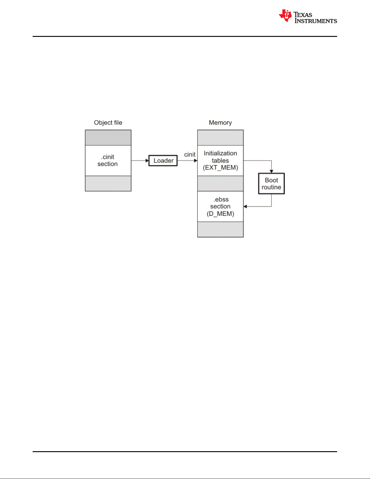
Program Loading and Running
www.ti.com
For the ROM model with EABI, the .cinit section is loaded into memory along with all the other initialized
sections. The linker defines a special symbol called __TI_CINIT_Base that points to the beginning of the
initialization tables in memory. When the program begins running, the C boot routine copies data from the tables
(pointed to by .cinit) into the run-time location of the variables.
For the ROM model with COFF, the .cinit section is loaded into memory along with all the other initialized
sections. The linker defines a special symbol called cinit that points to the beginning of the initialization tables in
memory. When the program begins running, the C boot routine copies data from the tables (pointed to by .cinit)
into the specified variables in the .ebss or user-defined section.
Figure 3-3 illustrates autoinitialization at run time for the COFF ABI using the ROM model.
Figure 3-3. Autoinitialization at Run Time
3.3.2.2 Initializing Variables at Load Time (--ram_model)
The RAM model Initializes variables at load time. To use this method, invoke the linker with the --ram_model
option.
This model may reduce boot time and save memory used by the initialization tables.
When you use the --ram_model linker option, the linker sets the STYP_COPY bit in the .cinit section's header.
This tells the loader not to load the .cinit section into memory. (The .cinit section occupies no space in the
memory map.)
For COFF, the linker also sets the cinit symbol to -1 (normally, cinit points to the beginning of the initialization
tables). This indicates to the boot routine that the initialization tables are not present in memory; accordingly, no
run-time initialization is performed at boot time.
For EABI, the linker sets __TI_CINIT_Base equal to __TI_CINIT_Limit to indicate there are no .cinit records.
A COFF loader must be able to perform the following tasks to use initialization at load time:
• Detect the presence of the .cinit section in the object file.
• Determine that STYP_COPY is set in the .cinit section header, so that it knows not to copy the .cinit section
into memory.
• Understand the format of the initialization tables.
For EABI, the loader copies values directly from the .data section to memory.
Figure 3-4 illustrates the initialization of variables at load time for the COFF ABI..
42 TMS320C28x Assembly Language Tools
v20.12.0.STS
SPRU513V – JULY 2001 – REVISED DECEMBER 2020
Submit Document Feedback
Copyright © 2020 Texas Instruments Incorporated
Page 43

www.ti.com
Program Loading and Running
Figure 3-4. Initialization at Load Time
3.3.2.3 The --rom_model and --ram_model Linker Options
The following list outlines what happens when you invoke the linker with the --ram_model or --rom_model option.
• The symbol _c_int00 is defined as the program entry point. The _c_int00 symbol is the start of the C boot
routine in boot.c.obj. Referencing _c_int00 ensures that boot.c.obj is automatically linked in from the
appropriate run-time-support library.
• For COFF, the .cinit output section is padded with a termination record to tell the boot routine (autoinitialize at
run time) or the loader (initialize at load time) when to stop reading initialization tables.
• When you use the ROM model to autoinitialize at run time (--rom_model option):
– For EABI, the linker defines a special symbol called __TI_CINIT_Base that points to the beginning of the
initialization tables in memory. When the program begins running, the C boot routine copies data from the
tables (pointed to by .cinit) into the run-time location of the variables.
– For COFF, the linker defines cinit as the starting address of the .cinit section. The C boot routine uses this
symbol as the starting point for autoinitialization.
• When you use the RAM model to initialize at load time (--ram_model option):
– For EABI, the linker sets __TI_CINIT_Base equal to __TI_CINIT_Limit to indicate there are no .cinit
records.
– For COFF, the linker sets cinit to -1. This indicates that the initialization tables are not in memory, so no
initialization is performed at run time. The linker sets the STYP_COPY flag (0010h) in the .cinit section
header. STYP_COPY is a special attribute that tells the loader to perform initialization directly and not to
load the .cinit section into memory. The linker does not allocate space in memory for the .cinit section.
Note
Loader
A loader is not included as part of the TMS320C28x C/C++ compiler tools. Use Code Composer
Studio as a loader.
3.3.3 About Linker-Generated Copy Tables
The RTS function copy_in can be used at run-time to move code and data around, usually from its load address
to its run address. This function reads size and location information from copy tables. The linker automatically
generates several kinds of copy tables. Refer to Section 8.8.
You can create and control code overlays with copy tables. See Section 8.8.4 for details and examples.
Copy tables can be used by the linker to implement run-time relocations as described in Section 3.5, however
copy tables require a specific table format.
SPRU513V – JULY 2001 – REVISED DECEMBER 2020
Submit Document Feedback
Copyright © 2020 Texas Instruments Incorporated
TMS320C28x Assembly Language Tools
v20.12.0.STS
43
Page 44

Program Loading and Running
www.ti.com
3.3.3.1 BINIT
The BINIT (boot-time initialization) copy table is special in that the target will automatically perform the copying at
auto-initialization time. Refer to Section 8.8.4.2 for more about the BINIT copy table name. The BINIT copy table
is copied before .cinit processing.
3.3.3.2 CINIT
EABI .cinit tables are special kinds of copy tables. Refer to Section 3.3.2.1 for more about using the .cinit section
with the ROM model and Section 3.3.2.2 for more using it with the RAM model.
COFF .cinit tables can be used to provide copy table functionality. See Section 8.8 for more information.
3.4 Arguments to main
Some programs expect arguments to main (argc, argv) to be valid. Normally this isn't possible for an embedded
program, but the TI runtime does provide a way to do it. The user must allocate an .args section of an
appropriate size using the --args linker option. It is the responsibility of the loader to populate the .args section. It
is not specified how the loader determines which arguments to pass to the target. The format of the arguments is
the same as an array of pointers to char on the target.
See Section 8.4.4 for information about allocating memory for argument passing.
3.5 Run-Time Relocation
At times you may want to load code into one area of memory and move it to another area before running it. For
example, you may have performance-critical code in an external-memory-based system. The code must be
loaded into external memory, but it would run faster in internal memory. Because internal memory is limited, you
might swap in different speed-critical functions at different times.
The linker provides a way to handle this. Using the SECTIONS directive, you can optionally direct the linker to
allocate a section twice: first to set its load address and again to set its run address. Use the load keyword for
the load address and the run keyword for the run address. See Section 3.1.1 for more about load and run
addresses. If a section is assigned two addresses at link time, all labels defined in the section are relocated to
refer to the run-time address so that references to the section (such as branches) are correct when the code
runs.
If you provide only one allocation (either load or run) for a section, the section is allocated only once and loads
and runs at the same address. If you provide both allocations, the section is actually allocated as if it were two
separate sections. The two sections are the same size if the load section is not compressed.
Uninitialized sections (such as .ebss or .bss) are not loaded, so the only significant address is the run address.
The linker allocates uninitialized sections only once; if you specify both run and load addresses, the linker warns
you and ignores the load address.
For a complete description of run-time relocation, see Section 8.5.6.
3.6 Additional Information
See the following sections and documents for additional information:
Section 8.4.4, "Allocate Memory for Use by the Loader to Pass Arguments (--arg_size Option)"
Section 8.4.13, "Define an Entry Point (--entry_point Option)"
Section 8.5.6.1 ,"Specifying Load and Run Addresses"
Section 8.8, "Linker-Generated Copy Tables"
Section 8.11.1, "Run-Time Initialization"
Chapter 12, "Hex Conversion Utility Description"
"Run-Time Initialization" and "System Initialization" sections in the TMS320C28x Optimizing C/C++ Compiler
User's Guide
44 TMS320C28x Assembly Language Tools
v20.12.0.STS
Copyright © 2020 Texas Instruments Incorporated
SPRU513V – JULY 2001 – REVISED DECEMBER 2020
Submit Document Feedback
Page 45

www.ti.com Assembler Description
Chapter 4
Assembler Description
The TMS320C28x assembler translates assembly language source files into machine language object files.
These files are object modules, which are discussed in Chapter 2. Source files can contain the following
assembly language elements:
Assembler directives described in Chapter 5
Macro directives described in Chapter 6
Assembly language instructions described in the TMS320C28x DSP CPU and Instruction Set Reference Guide.
4.1 Assembler Overview.................................................................................................................................................. 46
4.2 The Assembler's Role in the Software Development Flow.....................................................................................47
4.3 Invoking the Assembler............................................................................................................................................. 48
4.4 Controlling Application Binary Interface..................................................................................................................49
4.5 Naming Alternate Directories for Assembler Input................................................................................................. 49
4.6 Source Statement Format..........................................................................................................................................52
4.7 Literal Constants........................................................................................................................................................ 54
4.8 Assembler Symbols................................................................................................................................................... 57
4.9 Expressions................................................................................................................................................................ 63
4.10 Built-in Functions and Operators............................................................................................................................66
4.11 TMS320C28x Assembler Extensions......................................................................................................................67
4.12 Source Listings.........................................................................................................................................................69
4.13 Debugging Assembly Source..................................................................................................................................71
4.14 Cross-Reference Listings........................................................................................................................................ 72
4.15 Smart Encoding........................................................................................................................................................ 73
4.16 Pipeline Conflict Detection...................................................................................................................................... 74
SPRU513V – JULY 2001 – REVISED DECEMBER 2020
Submit Document Feedback
Copyright © 2020 Texas Instruments Incorporated
TMS320C28x Assembly Language Tools
v20.12.0.STS
45
Page 46

Assembler Description
www.ti.com
4.1 Assembler Overview
The 2-pass assembler does the following:
• Processes the source statements in a text file to produce a relocatable object file
• Produces a source listing (if requested) and provides you with control over this listing
• Allows you to divide your code into sections and maintain a section program counter (SPC) for each section
of object code
• Defines and references global symbols and appends a cross-reference listing to the source listing (if
requested)
• Allows conditional assembly
• Supports macros, allowing you to define macros inline or in a library
46 TMS320C28x Assembly Language Tools
v20.12.0.STS
SPRU513V – JULY 2001 – REVISED DECEMBER 2020
Submit Document Feedback
Copyright © 2020 Texas Instruments Incorporated
Page 47

C
source
files
C/C++
compiler
Assembler
source
Assembler
Library-build
utility
Run-time-
support
library
Archiver
Archiver
Macro
library
Linker
C2xx
assembler
source
Transition
assistant
Assembler
source
Macro
source
files
Object
files
Library of
object
files
Executable
object file
Debugging
tools
Absolute lister
Hex-conversion
utility
Cross-reference
lister
Object file
utilities
C28x
EPROM
programmer
Post-link
optimizer
www.ti.com
Assembler Description
4.2 The Assembler's Role in the Software Development Flow
Figure 4-1 illustrates the assembler's role in the software development flow. The shaded portion highlights the
most common assembler development path. The assembler accepts assembly language source files as input,
both those you create and those created by the TMS320C28x C/C++ compiler.
SPRU513V – JULY 2001 – REVISED DECEMBER 2020
Submit Document Feedback
Figure 4-1. The Assembler in the TMS320C28x Software Development Flow
Copyright © 2020 Texas Instruments Incorporated
TMS320C28x Assembly Language Tools
v20.12.0.STS
47
Page 48

Assembler Description www.ti.com
4.3 Invoking the Assembler
To invoke the assembler, enter the following:
cl2000 input file [options]
cl2000 is the command that invokes the assembler through the compiler. The compiler considers any file with an .asm extension
input file names the assembly language source file.
options identify the assembler options that you want to use. Options are case sensitive and can appear anywhere on the
to be an assembly file and invokes the assembler.
command line following the command. Precede each option with one or two hyphens as shown.
The valid assembler options are listed in Table 4-1.
Table 4-1. TMS320C28x Assembler Options
Option Alias Description
--absolute_listing -aa Creates an absolute listing. When you use --absolute_listing, the assembler does not produce
--asm_define=name[=def] -ad Sets the name symbol. This is equivalent to defining name with a .set directive in the case of a
--asm_dependency -apd Performs preprocessing for assembly files, but instead of writing preprocessed output, writes a
--asm_includes -api Performs preprocessing for assembly files, but instead of writing preprocessed output, writes a
--asm_listing -al Produces a listing file with the same name as the input file with a .lst extension.
--asm_listing_cross_reference -ax Produces a cross-reference table and appends it to the end of the listing file; it also adds cross-
--asm_undefine=name -au Undefines the predefined constant name, which overrides any --asm_define options for the
--cla_support[=cla0|cla1|cla2] Specifies TMS320C28x Control Law Accelerator (CLA) Type 0, Type 1, or Type 2 support. This
--cmd_file=filename -@ Appends the contents of a file to the command line. You can use this option to avoid limitations
--float_support={ fpu32 | fpu64 } Assembles code for C28x with 32-bit or 64-bit hardware FPU support.
--include_file=filename -ahi Includes the specified file for the assembly module. The file is included before source file
--include_path=pathname -I Specifies a directory where the assembler can find files named by the .copy, .include, or .mlib
--lfu_reference_elf=path lfu=pat
h
--quiet -q Suppresses the banner and progress information (assembler runs in quiet mode).
an object file. The --absolute_listing option is used in conjunction with the absolute lister.
numeric value or with an .asg directive otherwise. If value is omitted, the symbol is set to 1. See
Section 4.8.5.
list of dependency lines suitable for input to a standard make utility. The list is written to a file
with the same name as the source file but with a .ppa extension.
list of files included with the .include directive. The list is written to a file with the same name as
the source file but with a .ppa extension.
reference information to the object file for use by the cross-reference utility. If you do not
request a listing file but use the --asm_listing_cross_reference option, the assembler creates a
listing file automatically, naming it with the same name as the input file with a .lst extension.
specified constant.
option is used to compile or assemble code written for the CLA. This option does not need any
special library support when linking; the libraries used for C28x with/without FPU support
should be sufficient.
on command line length imposed by the host operating system. Use an asterisk or a semicolon
(* or ;) at the beginning of a line in the command file to include comments. Comments that
begin in any other column must begin with a semicolon. Within the command file, filenames or
option parameters containing embedded spaces or hyphens must be surrounded with quotation
marks. For example: "this-file.asm"
statements. The included file does not appear in the assembly listing files.
directives. There is no limit to the number of directories you can specify in this manner; each
pathname must be preceded by the --include_path option. See Section 4.5.1.
In order to create a Live Firmware Update (LFU) compatible executable binary, specify the path
to a previous ELF executable binary to use as a reference from which to obtain a list of the
memory addresses of global and static symbols. This previous binary may be an LFUcompatible binary, but this is not required. (LFU is supported for EABI only)
48 TMS320C28x Assembly Language Tools
v20.12.0.STS
SPRU513V – JULY 2001 – REVISED DECEMBER 2020
Submit Document Feedback
Copyright © 2020 Texas Instruments Incorporated
Page 49

www.ti.com
Assembler Description
Table 4-1. TMS320C28x Assembler Options (continued)
Option Alias Description
--symdebug:dwarf or
--symdebug:none
--vcu_support[=vcu0|vcu2|vcrc] The vcu0 and vcu2 settings specify there is support for Type 0 or Type 2 of the Viterbi, Complex
-g (DWARF is on by default) Enables assembler source debugging in the C source debugger. Line
information is output to the object module for every line of source in the assembly language
source file. You cannot use this option on assembly code that contains .line directives. See
Section 4.13.
Math and CRC Unit (VCU). Note that there is no VCU Type 1. The default is vcu0.
The vcrc setting specifies support for Cyclic Redundancy Check (CRC) algorithms only.
Support for vcrc is available only if FPU32 or FPU64 is used.
This option is useful only if the source is in assembly code, written for the VCU. The option is
ignored for C/C++ code. This option does not require any special library support from the linker;
the libraries used for C28x with/without VCU support should be sufficient.
4.4 Controlling Application Binary Interface
An Application Binary Interface (ABI) defines the low level interface between object files, and between an
executable and its execution environment. The ABI exists to allow ABI-compliant object code to link together,
regardless of its source, and allows the resulting executable to run on any system that supports that ABI.
The C28x Code Generation Tools support both the COFF ABI and the EABI ABI. The ABI used by the assembler
is determined by the --abi command-line option.
• COFF ABI: (--abi=coffabi, the default)
When using the COFF ABI, the output files are in COFF format. See the Common Object File Format
Application Report (SPRAAO8) for details.
• EABI: (--abi=eabi)
When using EABI, the output files are in Executable and Linking Format (ELF). See the TMS320C28x
Optimizing C/C++ Compiler User's Guide (SPRU514) and the C28x Embedded Application Binary Interface
Application Report (SPRAC71) for information on the EABI ABI.
All object files in an application must be built for the same ABI. The linker detects situations where object
modules conform to different ABIs and generates an error.
Converting an assembly file from the COFF API to EABI requires some changes to the assembly code. For
example, you would typically need to make the following changes when a memory section is referenced:
• .ebss to .bss
• .esysmem to .sysmem
• .econst to .const
• .pinit to .init_array
The examples in this guide are generally written for the COFF ABI.
4.5 Naming Alternate Directories for Assembler Input
The .copy, .include, and .mlib directives tell the assembler to use code from external files. The .copy and .include
directives tell the assembler to read source statements from another file, and the .mlib directive names a library
that contains macro functions. Chapter 5 contains examples of the .copy, .include, and .mlib directives. The
syntax for these directives is:
.copy
["]filename["]
.include ["]filename["]
.mlib ["]filename["]
The filename names a copy/include file that the assembler reads statements from or a macro library that
contains macro definitions. If filename begins with a number the double quotes are required. Quotes are
recommended so that there is no issue in dealing with path information that is included in the filename
SPRU513V – JULY 2001 – REVISED DECEMBER 2020
Submit Document Feedback
Copyright © 2020 Texas Instruments Incorporated
TMS320C28x Assembly Language Tools
v20.12.0.STS
49
Page 50

Assembler Description
www.ti.com
specification or path names that include white space. The filename may be a complete pathname, a partial
pathname, or a filename with no path information.
The assembler searches for the file in the following locations in the order given:
1. The directory that contains the current source file. The current source file is the file being assembled when
the .copy, .include, or .mlib directive is encountered.
2. Any directories named with the --include_path option
3. Any directories named with the C2000_A_DIR environment variable
4. Any directories named with the C2000_C_DIR environment variable
Because of this search hierarchy, you can augment the assembler's directory search algorithm by using the -include_path option (described in Section 4.5.1) or the C2000_A_DIR environment variable (described in
Section 4.5.2). The C2000_C_DIR environment variable is discussed in the TMS320C28x Optimizing C/C++
Compiler User's Guide.
4.5.1 Using the --include_path Assembler Option
The --include_path assembler option names an alternate directory that contains copy/include files or macro
libraries. The format of the --include_path option is as follows:
cl2000 --include_path= pathname source filename [other options]
There is no limit to the number of --include_path options per invocation; each --include_path option names one
pathname. In assembly source, you can use the .copy, .include, or .mlib directive without specifying path
information. If the assembler does not find the file in the directory that contains the current source file, it
searches the paths designated by the --include_path options.
For example, assume that a file called source.asm is in the current directory; source.asm contains the following
directive statement:
.copy "copy.asm"
Assume the following paths for the copy.asm file:
UNIX:
Windows: c:\tools\files\copy.asm
/tools/files/copy.asm
You could set up the search path with the commands shown below:
Operating System
UNIX (Bourne shell)
Windows
Enter
cl2000 --include_path=/tools/files source.asm
cl2000 --include_path=c:\tools\files source.asm
The assembler first searches for copy.asm in the current directory because source.asm is in the current
directory. Then the assembler searches in the directory named with the --include_path option.
50 TMS320C28x Assembly Language Tools
v20.12.0.STS
SPRU513V – JULY 2001 – REVISED DECEMBER 2020
Submit Document Feedback
Copyright © 2020 Texas Instruments Incorporated
Page 51

www.ti.com Assembler Description
4.5.2 Using the C2000_A_DIR Environment Variable
An environment variable is a system symbol that you define and assign a string to. The assembler uses the
C2000_A_DIR environment variable to name alternate directories that contain copy/include files or macro
libraries.
The assembler looks for the C2000_A_DIR environment variable and then reads and processes it. If the
assembler does not find the C2000_A_DIR variable, it then searches for C2000_C_DIR. The processor-specific
variables are useful when you are using Texas Instruments tools for different processors at the same time.
See the TMS320C28x Optimizing C/C++ Compiler User's Guide for details on C2000_C_DIR.
The command syntax for assigning the environment variable is as follows:
Operating System Enter
UNIX (Bourne Shell) C2000_A_DIR=" pathname1 ; pathname2 ; . . . "; export C2000_A_DIR
Windows set C2000_A_DIR= pathname1 ; pathname2 ; . . .
The pathnames are directories that contain copy/include files or macro libraries. The pathnames must follow
these constraints:
• Pathnames must be separated with a semicolon.
• Spaces or tabs at the beginning or end of a path are ignored. For example the space before and after the
semicolon in the following is ignored:
set C28X_A_DIR= c:\path\one\to\tools ; c:\path\two\to\tools
• Spaces and tabs are allowed within paths to accommodate Windows directories that contain spaces. For
example, the pathnames in the following are valid:
set C28X_A_DIR=c:\first path\to\tools;d:\second path\to\tools
In assembly source, you can use the .copy, .include, or .mlib directive without specifying path information. If the
assembler does not find the file in the directory that contains the current source file or in directories named by
the --include_path option, it searches the paths named by the environment variable.
For example, assume that a file called source.asm contains these statements:
.copy "copy1.asm"
.copy "copy2.asm"
Assume the following paths for the files:
UNIX:
Windows: c:\tools\files\copy1.asm and c:\dsys\copy2.asm
/tools/files/copy1.asm and /dsys/copy2.asm
You could set up the search path with the commands shown below:
Operating System
UNIX (Bourne shell)
Enter
C2000_A_DIR="/dsys"; export C2000_A_DIR
cl2000 --include_path=/tools/files source.asm
Windows
SPRU513V – JULY 2001 – REVISED DECEMBER 2020
Submit Document Feedback
C2000_A_DIR=c:\dsys
cl2000 --include_path=c:\tools\files source.asm
TMS320C28x Assembly Language Tools
Copyright © 2020 Texas Instruments Incorporated
v20.12.0.STS
51
Page 52

Assembler Description
www.ti.com
The assembler first searches for copy1.asm and copy2.asm in the current directory because source.asm is in
the current directory. Then the assembler searches in the directory named with the --include_path option and
finds copy1.asm. Finally, the assembler searches the directory named with C2000_A_DIR and finds copy2.asm.
The environment variable remains set until you reboot the system or reset the variable by entering one of these
commands:
Operating System Enter
UNIX (Bourne shell)
unset C2000_A_DIR
Windows
set C2000_A_DIR=
4.6 Source Statement Format
Each line in a TMS320C28x assembly input file can be empty, a comment, an assembler directive, a macro
invocation, or an assembly instruction.
Assembly language source statements can contain four ordered fields (label, mnemonic, operand list, and
comment). The general syntax for source statements is as follows:
[label[:] ] [||] mnemonic [operand list] [;comment]
Labels cannot be placed on instructions that have parallel bars.
Following are examples of source statements:
two .set 2 ; Symbol two = 2
Begin: MOV AR1,#two ; Load AR1 with 2
.word 016h ; Initialize a word with 016h
The C28x assembler reads an unlimited number of characters per line. Source statements that extend beyond
400 characters in length (including comments) are truncated in the listing file.
Follow these guidelines:
• All statements must begin with a label, a blank, an asterisk, or a semicolon.
• Labels are optional for most statements; if used, they must begin in column 1.
• One or more space or tab characters must separate each field.
• Comments are optional. Comments that begin in column 1 can begin with an asterisk or a semicolon (* or ;),
but comments that begin in any other column must begin with a semicolon.
Note
A mnemonic cannot begin in column 1 or it will be interpreted as a label. Mnemonic opcodes and
assembler directive names without the . prefix are valid label names. Remember to always use
whitespace before the mnemonic, or the assembler will think the identifier is a new label definition.
The following sections describe each of the fields.
52 TMS320C28x Assembly Language Tools
v20.12.0.STS
Copyright © 2020 Texas Instruments Incorporated
SPRU513V – JULY 2001 – REVISED DECEMBER 2020
Submit Document Feedback
Page 53

RPT
Inst2
||
Thisinstructionisrepeated.
Instr1
Instr2
||
www.ti.com
Assembler Description
4.6.1 Label Field
A label must be a legal identifier (see Section 4.8.1) placed in column 1. Every instruction may optionally have a
label. Many directives allow a label, and some require a label.
A label can be followed by a colon (:). The colon is not treated as part of the label name. If you do not use a
label, the first character position must contain a blank, a semicolon, or an asterisk.
When you use a label on an assembly instruction or data directive, an assembler symbol (Section 4.8) with the
same name is created. Its value is the current value of the section program counter (SPC, see Section 2.4.5).
This symbol represents the address of that instruction. In the following example, the .word directive is used to
create an array of 3 words. Because a label was used, the assembly symbol Start refers to the first word, and
the symbol will have the value 40h.
. . . .
9 * Assume some code was assembled
10 000040 000A Start: .word 0Ah,3,7
000044 0003
000048 0007
A label on a line by itself is a valid statement. When a label appears on a line by itself, it points to the instruction
on the next line (the SPC is not incremented):
1 000000 Here:
2 000000 0003 .word 3
A label on a line by itself is equivalent to writing:
Here: .equ $ ; $ provides the current value of the SPC
If you do not use a label, the character in column 1 must be a blank, an asterisk, or a semicolon.
4.6.2 Mnemonic Field
The mnemonic field follows the label field. The mnemonic field cannot start in column 1; if it does, it is interpreted
as a label. The mnemonic field can begin with pipe symbols (||) when the previous instruction is a RPT. Pipe
symbols that follow a RPT instruction indicate instructions that are repeated. For example:
In the case of C28x with FPU support, the mnemonic field can begin with pipe symbols to indicate instructions
that are to be executed in parallel. For example, in the instance given below, Inst1 and Inst2 are FPU instructions
that execute in parallel:
Next, the mnemonic field contains one of the following items:
• Machine-instruction mnemonic (such as ADD, MOV, or B)
• Assembler directive (such as .data, .list, .equ)
• Macro directive (such as .macro, .var, .mexit)
• Macro invocation
SPRU513V – JULY 2001 – REVISED DECEMBER 2020
Submit Document Feedback
Copyright © 2020 Texas Instruments Incorporated
TMS320C28x Assembly Language Tools
v20.12.0.STS
53
Page 54

Assembler Description
www.ti.com
4.6.3 Operand Field
The operand field follows the mnemonic field and contains zero or more comma-separated operands. An
operand can be one of the following:
• an immediate operand (usually a constant or symbol) (see Section 4.7 and Section 4.8)
• a register operand
• a memory reference operand
• an expression that evaluates to one of the above (see Section 4.9)
An immediate operand is encoded directly in the instruction. The value of an immediate operand must be a
constant expression. Most instructions with an immediate operand require an absolute constant expression,
such as 1234. Some instructions (such as a call instruction) allow a relocatable constant expression, such as a
symbol defined in another file. (See Section 4.9 for details about types of expressions.)
A register operand is a special pre-defined symbol that represents a CPU register.
A memory reference operand uses one of several memory addressing modes to refer to a location in memory.
Memory reference operands use a special target-specific syntax defined in the appropriate CPU and Instruction
Set Reference Guide.
You must separate operands with commas. Not all operand types are supported for all operands. See the
description of the specific instruction in the CPU and Instruction Set Reference Guide for your device family.
4.6.4 Comment Field
A comment can begin in any column and extends to the end of the source line. A comment can contain any
ASCII character, including blanks. Comments are printed in the assembly source listing, but they do not affect
the assembly.
A source statement that contains only a comment is valid. If it begins in column 1, it can start with a semicolon
( ; ) or an asterisk ( *). Comments that begin anywhere else on the line must begin with a semicolon. The
asterisk identifies a comment only if it appears in column 1.
4.7 Literal Constants
A literal constant (also known as a literal or in some other documents as an immediate value) is a value that
represents itself, such as 12, 3.14, or "hello".
The assembler supports several types of literals:
• Binary integer literals
• Octal integer literals
• Decimal integer literals
• Hexadecimal integer literals
• Character literals
• Character string literals
• Floating-point literals
Error checking for invalid or incomplete literals is performed.
4.7.1 Integer Literals
The assembler maintains each integer literal internally as a 32-bit signless quantity. Literals are considered
unsigned values, and are not sign extended. For example, the literal 00FFh is equal to 00FF (base 16) or 255
(base 10); it does not equal -1. which is 0FFFFFFFFh (base 16). Note that if you store 0FFh in a .byte location,
the bits will be exactly the same as if you had stored -1. It is up to the reader of that location to interpret the
signedness of the bits.
54 TMS320C28x Assembly Language Tools
v20.12.0.STS
SPRU513V – JULY 2001 – REVISED DECEMBER 2020
Submit Document Feedback
Copyright © 2020 Texas Instruments Incorporated
Page 55

www.ti.com Assembler Description
4.7.1.1 Binary Integer Literals
A binary integer literal is a string of up to 32 binary digits (0s and 1s) followed by the suffix B (or b). Binary literals
of the form "0[bB][10]+" are also supported. If fewer than 32 digits are specified, the assembler right justifies the
value and fills the unspecified bits with zeros. These are examples of valid binary literals:
00000000B Literal equal to 010 or 0
0100000b Literal equal to 3210 or 20
01b Literal equal to 110 or 1
11111000B Literal equal to 24810 or 0F8
0b00101010 Literal equal to 4210 or 2A
0B101010 Literal equal to 4210 or 2A
16
16
16
16
16
16
4.7.1.2 Octal Integer Literals
An octal integer literal is a string of up to 11 octal digits (0 through 7) followed by the suffix Q (or q). Octal literals
may also begin with a 0, contain no 8 or 9 digits, and end with no suffix. These are examples of valid octal
literals:
10Q Literal equal to 810 or 8
054321 Literal equal to 2273710 or 58D1
100000Q Literal equal to 3276810 or 8000
226q Literal equal to 15010 or 96
16
16
16
16
4.7.1.3 Decimal Integer Literals
A decimal integer literal is a string of decimal digits ranging from -2147 483 648 to 4 294 967 295. These are
examples of valid decimal integer literals:
1000
-32768 Literal equal to -32 76810 or -8000
25 Literal equal to 2510 or 19
4815162342 Literal equal to 481516234210 or 11F018BE6
Literal equal to 100010 or 3E8
16
16
16
16
SPRU513V – JULY 2001 – REVISED DECEMBER 2020
Submit Document Feedback
Copyright © 2020 Texas Instruments Incorporated
TMS320C28x Assembly Language Tools
v20.12.0.STS
55
Page 56

Assembler Description
www.ti.com
4.7.1.4 Hexadecimal Integer Literals
A hexadecimal integer literal is a string of up to eight hexadecimal digits followed by the suffix H (or h) or
preceded by 0x. A hexadecimal literal must begin with a decimal value (0-9) if it is indicated by the H or h suffix.
Hexadecimal digits include the decimal values 0-9 and the letters A-F or a-f. If fewer than eight hexadecimal
digits are specified, the assembler right-justifies the bits.
These are examples of valid hexadecimal literals:
78h Literal equal to 12010 or 0078
0x78 Literal equal to 12010 or 0078
0Fh Literal equal to 1510 or 000F
37ACh Literal equal to 1425210 or 37AC
16
16
16
16
4.7.1.5 Character Literals
A character literal is a single character enclosed in single quotes. The characters are represented internally as 8bit ASCII characters. Two consecutive single quotes are required to represent each single quote that is part of a
character literal. A character literal consisting only of two single quotes is valid and is assigned the value 0.
These are examples of valid character literals:
'a' Defines the character literal a and is represented internally as 61
'C' Defines the character literal C and is represented internally as 43
'''' Defines the character literal ' and is represented internally as 27
'' Defines a null character and is represented internally as 00
Notice the difference between character literals and character string literals (Section 4.7.2 discusses character strings). A character literal
represents a single integer value; a string is a sequence of characters.
16
16
16
16
4.7.2 Character String Literals
A character string is a sequence of characters enclosed in double quotes. Double quotes that are part of
character strings are represented by two consecutive double quotes. The maximum length of a string varies and
is defined for each directive that requires a character string. Characters are represented internally as 8-bit ASCII
characters.
These are examples of valid character strings:
"sample program"
"PLAN ""C""" defines the 8-character string PLAN "C".
defines the 14-character string sample program.
Character strings are used for the following:
• Filenames, as in .copy "filename"
• Section names, as in .sect "section name"
• Data initialization directives, as in .byte "charstring"
• Operands of .string directives
56 TMS320C28x Assembly Language Tools
v20.12.0.STS
Copyright © 2020 Texas Instruments Incorporated
SPRU513V – JULY 2001 – REVISED DECEMBER 2020
Submit Document Feedback
Page 57

www.ti.com
Assembler Description
4.7.3 Floating-Point Literals
A floating-point literal is a string of decimal digits followed by a required decimal point, an optional fractional
portion, and an optional exponent portion. The syntax for a floating-point number is:
[ +|- ] nnn . [ nnn] [ E|e [ +|- ] nnn ]
Replace nnn with a string of decimal digits. You can precede nnn with a + or a -. You must specify a decimal
point. For example, 3.e5 is valid, but 3e5 is not valid. The exponent indicates a power of 10. These are
examples of valid floating-point literals:
3.0
3.14
3.
-0.314e13
+314.59e-2
The assembler syntax does not support all C89-style float literals nor C99-style hexadecimal constants, but the
$strtod built-in mathematical function supports both. If you want to specify a floating-point literal using one of
those formats, use $strtod. For example:
$strtod(".3")
$strtod("0x1.234p-5")
You cannot directly use NaN, Inf, or -Inf as floating-point literals. Instead, use $strtod to express these values.
The "NaN" and "Inf" strings are handled case-insensitively.
$strtod("NaN")
$strtod("Inf")
4.8 Assembler Symbols
An assembler symbol is a named 32-bit signless integer value, usually representing an address or absolute
integer. A symbol can represent such things as the starting address of a function, variable, or section. The name
of a symbol must be a legal identifier. The identifier becomes a symbolic representation of the symbol's value,
and may be used in subsequent instructions to refer to the symbol's location or value.
Some assembler symbols become external symbols, and are placed in the object file's symbol table. A symbol is
valid only within the module in which it is defined, unless you use the .global directive or the .def directive to
declare it as an external symbol (see .global directive).
See Section 2.6 for more about symbols and the symbol tables in object files.
4.8.1 Identifiers
Identifiers are names used as labels, registers, symbols, and substitution symbols. An identifier is a string of
alphanumeric characters, the dollar sign, and underscores (A-Z, a-z, 0-9, $, and _). The first character in an
identifier cannot be a number, and identifiers cannot contain embedded blanks. The identifiers you define are
case sensitive; for example, the assembler recognizes ABC, Abc, and abc as three distinct identifiers.
4.8.2 Labels
An identifier used as a label becomes an assembler symbol, which represent an address in the program. Labels
within a file must be unique.
Note
A mnemonic cannot begin in column 1 or it will be interpreted as a label. Mnemonic opcodes and
assembler directive names without the . prefix are valid label names. Remember to always use
whitespace before the mnemonic, or the assembler will think the identifier is a new label definition.
SPRU513V – JULY 2001 – REVISED DECEMBER 2020
Submit Document Feedback
Copyright © 2020 Texas Instruments Incorporated
TMS320C28x Assembly Language Tools
v20.12.0.STS
57
Page 58

Assembler Description
www.ti.com
Symbols derived from labels can also be used as the operands of .bss, .global, .ref, or .def directives.
.global label1
label2: NOP
ADD AR1, label1
SB label2, UNC
4.8.3 Local Labels
Local labels are special labels whose scope and effect are temporary. A local label can be defined in two ways:
• $n, where n is a decimal digit in the range 0-9. For example, $4 and $1 are valid local labels. See Example
4-1.
• name?, where name is any legal identifier as described above. The assembler replaces the question mark
with a period followed by a unique number. When the source code is expanded, you will not see the unique
number in the listing file. Your label appears with the question mark as it did in the source definition. See
Example 4-2.
You cannot declare these types of labels as global.
Normal labels must be unique (they can be declared only once), and they can be used as constants in the
operand field. Local labels, however, can be undefined and defined again. Local labels cannot be defined by
directives.
A local label can be undefined or reset in one of these ways:
• By using the .newblock directive
• By changing sections (using a .sect, .text, or .data directive)
• By entering an include file (specified by the .include or .copy directive)
• By leaving an include file (specified by the .include or .copy directive)
Example 4-1. Local Labels of the Form $n
This is an example of code that declares and uses a local label legally:
$1:
ADDB AL, #-7
B $1, GEQ
.newblock ; undefine $1 to use it again.
$1 MOV T, AL
MPYB ACC, T, #7
CMP AL, #1000
B $1, LT
The following code uses a local label illegally:
$1:
ADDB AL, #-7
B $1, GEQ
$1 MOV T, AL ; WRONG - $1 is multiply defined.
MPYB ACC, T, #7
CMP AL, #1000
B $1, LT
The $1 label is not undefined before being reused by the second branch instruction. Therefore, $1 is redefined,
which is illegal.
Local labels are especially useful in macros. If a macro contains a normal label and is called more than once, the
assembler issues a multiple-definition error. If you use a local label and .newblock within a macro, however, the
local label is used and reset each time the macro is expanded.
58 TMS320C28x Assembly Language Tools
v20.12.0.STS
SPRU513V – JULY 2001 – REVISED DECEMBER 2020
Submit Document Feedback
Copyright © 2020 Texas Instruments Incorporated
Page 59

www.ti.com
Assembler Description
Up to ten local labels of the $n form can be in effect at one time. Local labels of the form name? are not limited.
After you undefine a local label, you can define it and use it again. Local labels do not appear in the object code
symbol table.
Example 4-2. Local Labels of the Form name?
****************************************************************
** First definition of local label mylab **
****************************************************************
nop
mylab? nop
B mylab?, UNC
****************************************************************
** Include file has second definition of mylab **
****************************************************************
.copy "a.inc"
****************************************************************
** Third definition of mylab, reset upon exit from .include **
****************************************************************
mylab? nop
B mylab?, UNC
****************************************************************
** Fourth definition of mylab in macro, macros use different **
** namespace to avoid conflicts **
****************************************************************
mymac .macro
mylab? nop
B mylab?, UNC
.endm
****************************************************************
** Macro invocation **
****************************************************************
mymac
****************************************************************
** Reference to third definition of mylab. Definition is not **
** reset by macro invocation. **
****************************************************************
B mylab?, UNC
****************************************************************
** Changing section, allowing fifth definition of mylab **
****************************************************************
.sect "Sect_One"
nop
mylab? .word 0
nop
nop
B mylab?, UNC
****************************************************************
** The .newblock directive allows sixth definition of mylab **
****************************************************************
.newblock
mylab? .word 0
nop
nop
B mylab?, UNC
For more information about using labels in macros see Section 6.6.
4.8.4 Symbolic Constants
A symbolic constant is a symbol with a value that is an absolute constant expression (see Section 4.9). By using
symbolic constants, you can assign meaningful names to constant expressions. The .set
and .struct/.tag/.endstruct directives enable you to set symbolic constants (see Define Assembly-Time Constant).
Once defined, symbolic constants cannot be redefined.
SPRU513V – JULY 2001 – REVISED DECEMBER 2020
Submit Document Feedback
Copyright © 2020 Texas Instruments Incorporated
TMS320C28x Assembly Language Tools
v20.12.0.STS
59
Page 60

Assembler Description www.ti.com
If you use the .set directive to assign a value to a symbol , the symbol becomes a symbolic constant and may be
used where a constant expression is expected. For example:
shift3 .set 3
MOV AR1, #shift3
You can also use the .set directive to assign symbolic constants for other symbols, such as register names. In
this case, the symbolic constant becomes a synonym for the register:
myReg .set AR1
MOV myReg, #3
The following example shows how the .set directive can be used with the .struct, .tag. and .endstruct directives.
It creates the symbolic constants K, maxbuf, item, value, delta, and i_len.
K .set 1024 ; constant definitions
maxbuf .set 2*K
item .struct ; item structure definition
value .int ; value offset = 0
delta .int ; delta offset = 4
i_len .endstruct ; item size = 8
array .tag item
array .usect ".ebss", i_len*K ; declare an array of K "items"
.text
MOV array.delta, AR1 ; access array .delta
The assembler also has many predefined symbolic constants; these are discussed in Section 4.8.6.
4.8.5 Defining Symbolic Constants (--asm_define Option)
The --asm_define option equates a constant value or a string with a symbol. The symbol can then be used in
place of a value in assembly source. The format of the --asm_define option is as follows:
cl2000 --asm_define=
name[= value]
The name is the name of the symbol you want to define. The value is the constant or string value you want to
assign to the symbol. If the value is omitted, the symbol is set to 1. If you want to define a quoted string and keep
the quotation marks, do one of the following:
• For Windows, use --asm_define= name ="\" value \"". For example, --asm_define=car="\"sedan\""
• For UNIX, use --asm_define= name ='" value "'. For example, --asm_define=car='"sedan"'
• For Code Composer, enter the definition in a file and include that file with the --cmd_file (or -@) option.
Once you have defined the name with the --asm_define option, the symbol can be used with assembly directives
and instructions as if it had been defined with the .set directive. For example, on the command line you enter:
cl2000 --asm_define=SYM1=1 --asm_define=SYM2=2 --asm_define=SYM3=3 --asm_define=SYM4=4 value.asm
Since you have assigned values to SYM1, SYM2, SYM3, and SYM4, you can use them in source code. Example
4-3 shows how the value.asm file uses these symbols without defining them explicitly.
In assembler source, you can test the symbol defined with the --asm_define option with these directives:
Type of Test
Existence .if $isdefed(" name ")
Nonexistence .if $isdefed(" name ") = 0
Equal to value .if name = value
Not equal to value .if name != value
Directive Usage
60 TMS320C28x Assembly Language Tools
v20.12.0.STS
SPRU513V – JULY 2001 – REVISED DECEMBER 2020
Submit Document Feedback
Copyright © 2020 Texas Instruments Incorporated
Page 61

www.ti.com
Assembler Description
The argument to the $isdefed built-in function must be enclosed in quotes. The quotes cause the argument to be
interpreted literally rather than as a substitution symbol.
Example 4-3. Using Symbolic Constants Defined on Command Line
IF_4: .if SYM4 = SYM2 * SYM2
.byte SYM4 ; Equal values
.else
.byte SYM2 * SYM2 ; Unequal values
.endif
IF_5: .if SYM1 <= 10
.byte 10 ; Less than / equal
.else
.byte SYM1 ; Greater than
.endif
IF_6: .if SYM3 * SYM2 != SYM4 + SYM2
.byte SYM3 * SYM2 ; Unequal value
.else
.byte SYM4 + SYM4 ; Equal values
.endif
IF_7: .if SYM1 = SYM2
.byte SYM1
.elseif SYM2 + SYM3 = 5
.byte SYM2 + SYM3
.endif
4.8.6 Predefined Symbolic Constants
The assembler has several types of predefined symbols.
$, the dollar-sign character, represents the current value of the section program counter (SPC). $ is a relocatable
symbol if you are using COFF.
In addition, the following predefined processor symbolic constants are available:
Table 4-2. C28x Processor Symbolic Constants
Symbol name Description
__TI_EABI__ Set to 1 if EABI is enabled. Otherwise, COFF is used.
.TMS320C2000 Always set to 1
.TMS320C2800 Set to 1 for C28x
.TMS320C2800_CLA0 Set to 1 if --cla_support=cla0 or greater is used.
.TMS320C2800_CLA1 Set to 1 if --cla_support=cla1 or greater is used.
.TMS320C2800_CLA2 Set to 1 if --cla_support=cla2 is used.
.TMS320C2800_FPU32 Set to 1 if --float_support=fpu32 is used, otherwise 0.
.TMS320C2800_FPU64 Set to 1 if --float_support=fpu64 is used, otherwise 0.
.TMS320C2800_IDIV Set to 1 if --idiv_support=idiv0 is used.
.TMS320C2800_TMU0 Set to 1 if --tmu_support=tmu0 or greater is used.
.TMS320C2800_TMU1 Set to 1 if --tmu_support=tmu1 or greater is used.
.TMS320C2800_VCU0 Set to 1 if --vcu_support=vcu0 or greater is used.
.TMS320C2800_VCU2 Set to 1 if --vcu_support=vcu2 or greater is used.
.TMS320C2800_VCRC Set to 1 if --vcu_support=vcrc is used.
4.8.7 Registers
The names of C28x registers are predefined symbols.
In addition, control register names are predefined symbols.
Register symbols and aliases can be entered as all uppercase or all lowercase characters.
SPRU513V – JULY 2001 – REVISED DECEMBER 2020
Submit Document Feedback
Copyright © 2020 Texas Instruments Incorporated
TMS320C28x Assembly Language Tools
v20.12.0.STS
61
Page 62

Assembler Description www.ti.com
Control register symbols can be entered in all upper-case or all lower-case characters. For example, IER can
also be entered as ier.
See the "Register Conventions" section of the TMS320C28x Optimizing C/C++ Compiler User's Guide for details
about the registers and their uses.
Table 4-3. CPU and CPU Control Registers
Register Description
ACC/AH, AL Accumulator/accumulator high, accumulator low
DBGIER Debug interrupt enable register
DP Data page pointer
IER Interrupt enable register
IFR Interrupt flag pointer
P/PH, PL Product register/product high, product low
PC Program counter
RPC Return program counter
ST0 Status register 0
ST1 Status register 1
SP Stack pointer register
TH Multiplicant high register; an alias of T register
XAR0/AR0H, AR0 Auxiliary register 0/auxiliary 0 high, auxiliary 0 low
XAR1/AR1H, AR1 Auxiliary register 1/auxiliary 1 high, auxiliary 1 low
XAR2/AR2H, AR2 Auxiliary register 2/auxiliary 2 high, auxiliary 2 low
XAR3/AR3H, AR3 Auxiliary register 3/auxiliary 3 high, auxiliary 3 low
XAR4/AR4H, AR4 Auxiliary register 4/auxiliary 4 high, auxiliary 4 low
XAR5/AR5H, AR5 Auxiliary register 5/auxiliary 5 high, auxiliary 5 low
XAR6/AR6H, AR6 Auxiliary register 6/auxiliary 6 high, auxiliary 6 low
XAR7/AR7H, AR7 Auxiliary register 7/auxiliary 7 high, auxiliary 7 low
XT/T, TL Multiplicand register/Multiplicant high, multiplicant low
Table 4-4. FPU and FPU Control Registers
Register Description
R0H Floating point register 0
R1H Floating point register 1
R2H Floating point register 2
R3H Floating point register 3
R4H Floating point register 4
R5H Floating point register 5
R6H Floating point register 6
R7H Floating point register 7
STF Floating point status register
RB Repeat block register
Table 4-5. VCU Registers
Register Description
VSTATUS VCU status and control register
VR0-VR8 VCU registers
VT0, VT1 VCU transition bit registers
VCRC VCU CRC result register
62 TMS320C28x Assembly Language Tools
v20.12.0.STS
SPRU513V – JULY 2001 – REVISED DECEMBER 2020
Submit Document Feedback
Copyright © 2020 Texas Instruments Incorporated
Page 63

www.ti.com
Assembler Description
4.8.8 Substitution Symbols
Symbols can be assigned a string value. This enables you to create aliases for character strings by equating
them to symbolic names. Symbols that represent character strings are called substitution symbols. When the
assembler encounters a substitution symbol, its string value is substituted for the symbol name. Unlike symbolic
constants, substitution symbols can be redefined.
A string can be assigned to a substitution symbol anywhere within a program; for example:
.asg "AR1", myReg ;register AR1
.asg "*+XAR2 [2]", ARG1 ;first arg
.asg "*+XAR2 [1]", ARG2 ;second arg
When you are using macros, substitution symbols are important because macro parameters are actually
substitution symbols that are assigned a macro argument. The following code shows how substitution symbols
are used in macros:
add2 .macro A, B ; add2 macro definition
MOV AL, A
ADD AL, B
.endm
*add2 invocation
add2 LOC1, LOC2 ;add "LOC1" argument to a
;second argument "LOC2".
MOV AL,LOC1
ADD AL,LOC2
See Chapter 6 for more information about macros.
4.9 Expressions
Nearly all values and operands in assembly language are expressions, which may be any of the following:
• a literal constant
• a register
• a register pair
• a memory reference
• a symbol
• a built-in function invocation
• a mathematical or logical operation on one or more expressions
This section defines several types of expressions that are referred to throughout this document. Some instruction
operands accept limited types of expressions. For example, the .if directive requires its operand be an absolute
constant expression with an integer value. Absolute in the context of assembly code means that the value of the
expression must be known at assembly time.
A constant expression is any expression that does not in any way refer to a register or memory reference. An
immediate operand will usually not accept a register or memory reference. It must be given a constant
expression. Constant expressions may be any of the following:
• a literal constant
• an address constant expression
• a symbol whose value is a constant expression
• a built-in function invocation on a constant expression
• a mathematical or logical operation on one or more constant expressions
An address constant expression is a special case of a constant expression. Some immediate operands that
require an address value can accept a symbol plus an addend; for example, some branch instructions. The
symbol must have a value that is an address, and it may be an external symbol. The addend must be an
absolute constant expression with an integer value. For example, a valid address constant expression is "array
+4".
SPRU513V – JULY 2001 – REVISED DECEMBER 2020
Submit Document Feedback
Copyright © 2020 Texas Instruments Incorporated
TMS320C28x Assembly Language Tools
v20.12.0.STS
63
Page 64

Assembler Description www.ti.com
A constant expression may be absolute or relocatable. Absolute means known at assembly time. Relocatable
means constant, but not known until link time. External symbols are relocatable, even if they refer to a symbol
defined in the same module.
An absolute constant expression may not refer to any external symbols anywhere in the expression. In other
words, an absolute constant expression may be any of the following:
• a literal constant
• an absolute address constant expression
• a symbol whose value is an absolute constant expression
• a built-in function invocation whose arguments are all absolute constant expressions
• a mathematical or logical operation on one or more absolute constant expressions
A relocatable constant expression refers to at least one external symbol. For ELF, such expressions may contain
at most one external symbol. A relocatable constant expression may be any of the following:
• an external symbol
• a relocatable address constant expression
• a symbol whose value is a relocatable constant expression
• a built-in function invocation with any arguments that are relocatable constant expressions
• a mathematical or logical operation on one or more expressions, at least one of which is a relocatable
constant expression
In some cases, the value of a relocatable address expression may be known at assembly time. For example, a
relative displacement branch may branch to a label defined in the same section.
4.9.1 Mathematical and Logical Operators
The operands of a mathematical or logical operator must be well-defined expressions. That is, you must use the
correct number of operands and the operation must make sense. For example, you cannot take the XOR of a
floating-point value. In addition, well-defined expressions contain only symbols or assembly-time constants that
have been defined before they occur in the directive's expression.
Three main factors influence the order of expression evaluation:
Parentheses
Precedence groups Operators, listed in Table 4-6, are divided into nine precedence groups. When parentheses do not determine
Left-to-right evaluation When parentheses and precedence groups do not determine the order of expression evaluation, the
Expressions enclosed in parentheses are always evaluated first.
8 / (4 / 2) = 4, but 8 / 4 / 2 = 1
You cannot substitute braces ( { } ) or brackets ( [ ] ) for parentheses.
the order of expression evaluation, the highest precedence operation is evaluated first.
8 + 4 / 2 = 10 (4 / 2 is evaluated first)
expressions are evaluated from left to right, except for Group 1, which is evaluated from right to left.
8 / 4*2 = 4, but 8 / (4*2) = 1
Table 4-6 lists the operators that can be used in expressions, according to precedence group.
Table 4-6. Operators Used in Expressions (Precedence)
(1)
Group
1 +
2 *
3 +
4 <<
Operator Description
-
~
!
/
%
-
>>
Unary plus
Unary minus
1s complement
Logical NOT
Multiplication
Division
Modulo
Addition
Subtraction
Shift left
Shift right
(2)
64 TMS320C28x Assembly Language Tools
v20.12.0.STS
SPRU513V – JULY 2001 – REVISED DECEMBER 2020
Submit Document Feedback
Copyright © 2020 Texas Instruments Incorporated
Page 65

www.ti.com
Assembler Description
Table 4-6. Operators Used in Expressions (Precedence) (continued)
(1)
Group
5 <
6 =[=]
7 & Bitwise AND
8 ^ Bitwise exclusive OR (XOR)
9 | Bitwise OR
(1) Group 1 operators are evaluated right to left. All other operators are evaluated left to right.
(2) Unary + and - have higher precedence than the binary forms.
Operator Description
<=
>
>=
!=
Less than
Less than or equal to
Greater than
Greater than or equal to
Equal to
Not equal to
(2)
The assembler checks for overflow and underflow conditions when arithmetic operations are performed during
assembly. It issues a warning (the "value truncated" message) whenever an overflow or underflow occurs. The
assembler does not check for overflow or underflow in multiplication.
4.9.2 Relational Operators and Conditional Expressions
The assembler supports relational operators that can be used in any expression; they are especially useful for
conditional assembly. Relational operators include the following:
= Equal to ! = Not equal to
< Less than <= Less than or equal to
> Greater than > = Greater than or equal to
Conditional expressions evaluate to 1 if true and 0 if false and can be used only on operands of equivalent
types; for example, absolute value compared to absolute value, but not absolute value compared to relocatable
value.
4.9.3 Well-Defined Expressions
Some assembler directives, such as .if, require well-defined absolute constant expressions as operands. Welldefined expressions contain only symbols or assembly-time constants that have been defined before they occur
in the directive's expression. In addition, they must use the correct number of operands and the operation must
make sense. The evaluation of a well-defined expression must be unambiguous.
This is an example of a well-defined expression:
1000h+X
where X was previously defined as an absolute symbol.
4.9.4 Legal Expressions
With the exception of the following expression contexts, there is no restriction on combinations of operations,
constants, internally defined symbols, and externally defined symbols.
When an expression contains more than one relocatable symbol or cannot be evaluated during assembly, the
assembler encodes a relocation expression in the object file that is later evaluated by the linker. If the final value
of the expression is larger in bits than the space reserved for it, you receive an error message from the linker.
See Section 2.7 for more information on relocation expressions.
When using the register relative addressing mode, the expression in brackets or parenthesis must be a welldefined expression, as described in Section 4.9.3. For example:
*+XA4[7]
SPRU513V – JULY 2001 – REVISED DECEMBER 2020
Submit Document Feedback
Copyright © 2020 Texas Instruments Incorporated
TMS320C28x Assembly Language Tools
v20.12.0.STS
65
Page 66

Assembler Description www.ti.com
4.10 Built-in Functions and Operators
The assembler supports built-in mathematical functions and built-in addressing operators.
The built-in substitution symbol functions are discussed in Section 6.3.2.
4.10.1 Built-In Math and Trigonometric Functions
The assembler supports many built-in mathematical functions. The built-in functions always return a value and
they can be used in conditional assembly or any place where a constant can be used.
In Table 4-7 x, y and z are type float, n is an int. The functions $cvi, $int and $sgn return an integer and all other
functions return a float. Angles for trigonometric functions are expressed in radians.
Table 4-7. Built-In Mathematical Functions
Function Description
$acos(x) Returns cos-1(x) in range [0, π], -1<=x<=1
$asin(x) Returns sin-1(x) in range [-π/2, π/2], -1<=x<=1
$atan x) Returns tan-1(x) in range [-π/2, π/2]
$atan2(x, y) Returns tan-1(y/x) in range [-π, π]
$ceil(x) Returns the smallest integer not less than x, as a float
$cos(x) Returns the cosine of x
$cosh(x) Returns the hyperbolic cosine of x
$cvf(n) Converts an integer to a float
$cvi(x) Converts a float to an integer. Returns an integer.
$exp(x) Returns the exponential function e
$fabs(x) Returns the absolute value |x|
$floor(x) Returns the largest integer not greater than x, as a float
$fmod(x, y) Returns the floating-point remainder of x/y, with the same sign as x
$int(x) Returns 1 if x has an integer value; else returns 0. Returns an integer.
$ldexp(x, n) Multiplies x by an integer power of 2. That is, x × 2
$log(x) Returns the natural logarithm ln(x), where x>0
$log10(x) Returns the base-10 logarithm log10(x), where x>0
$max(x, y, ...z) Returns the greatest value from the argument list
$min(x, y, ...z) Returns the smallest value from the argument list
$pow(x, y) Returns x
$round(x) Returns x rounded to the nearest integer
$sgn(x) Returns the sign of x. Returns 1 if x is positive, 0 if x is zero, and -1 if x is negative. Returns an integer.
$sin(x) Returns the sine of x
$sinh(x) Returns the hyperbolic sine of x
$sqrt(x) Returns the square root of x, x≥0
$strtod(str) Converts a character string to a double precision floating-point value. The string contains a properly-formatted
C99-style floating-point literal.
$tan(x) Returns the tangent of x
$tanh(x) Returns the hyperbolic tangent of x
$trunc(x) Returns x truncated toward 0
y
x
n
66 TMS320C28x Assembly Language Tools
v20.12.0.STS
SPRU513V – JULY 2001 – REVISED DECEMBER 2020
Submit Document Feedback
Copyright © 2020 Texas Instruments Incorporated
Page 67

www.ti.com
Assembler Description
4.11 TMS320C28x Assembler Extensions
The C28x assembler operates with a variety of extensions. These extensions are controlled by options as
follows:
-v28: The -v28 is the default, and no other silicon version is supported for the -v option. Therefore you do not
need to specify -v28 explicitly.
--cla_support: Accept CLA instructions. To support special floating point instructions that run on the Control Law
Accelerator (CLA), the assembler operates with CLA extensions. Section 4.11.3 describes the CLA support. CLA
Type 0, Type 1, or Type 2 can be specified. This extension is controlled by the following option: -cla_support=[cla0|cla1|cla2].
--float_support: Accept FPU32 or FPU64 instructions. Support is available for special floating point instructions
when a 32-bit or 64-bit floating point unit (FPU) is available. Section 4.11.2 describes the FPU support. This
extension is controlled by the following option: --float_support=[fpu32|fpu64].
--idiv_support: Substitute fast integer division instructions. These instructions support division and modulo
operations. This extension is controlled by the following option: --idiv_support=idiv0.
--tmu_support: Substitute TMU instructions. To support the Trigonometric Math Unit (TMU), TMU instructions
are used for floating point division and trigonometric functions. The options are tmu0 (default) and tmu1. The
tmu1 setting provides support for all tmu0 functionality plus the LOG2F32 and IEXP2F32 instructions. This
extension is controlled by the following option: --tmu_support=[tmu0|tmu1].
--vcu_support: Accept VCU instructions in assembly code. To support the Viterbi, Complex Math and CRC Unit
(VCU) instructions, the assembler operates with VCU support. The VCU Type 0, Type 2, or Cyclic Redundancy
Check (CRC) option can be specified. Note that there is no VCU Type 1. This option does not require any
special library support from the linker; the libraries used for C28x with/without VCU support should be sufficient.
• The vcu0 setting specifies there is support for Type 0 of the VCU. This is the default.
• The vcu2 setting specifies there is support for Type 2 of the VCU.
• The vcrc setting specifies support for Cyclic Redundancy Check (CRC) algorithms only. Support for vcrc is
available only if FPU32 or FPU64 support is used.
Refer to the TMS320C28x DSP CPU and Instruction Set Reference Guide for more details on the different object
and addressing extensions supported by the C28x processor.
4.11.1 C28x Support
The default support includes all the C28x instructions and generates C28x object code.
An error occurs if old C27x syntax is used. For example, the following instructions are illegal:
MOV AL, *AR0++ ; *AR0++ is illegal addressing for C28x.
SPRU513V – JULY 2001 – REVISED DECEMBER 2020
Submit Document Feedback
Copyright © 2020 Texas Instruments Incorporated
TMS320C28x Assembly Language Tools
v20.12.0.STS
67
Page 68

Assembler Description
www.ti.com
4.11.2 C28x FPU32 and FPU64 Extensions
FPU instructions may be used when the 32-bit or 64-bit floating-point co-processor hardware is available on the
C28x.
FPU32 instructions are enabled by specifying the --float_support=fpu32 option. FPU32 instructions are
supported for both the COFF ABI and EABI.
FPU64 instructions are enabled by specifying the --float_support=fpu64 option. The FPU64 instruction set
includes all of the FPU32 instructions plus some additional 64-bit instructions. FPU64 is supported only for EABI.
When FPU support is enabled, the differences are as follows:
• Some special floating point instructions are supported. These are documented in the TMS320C28x Floating
Point Unit and Instruction Set Reference Guide.
• The assembler checks for pipeline conflicts. This is because the FPU instructions are not pipeline protected.
Regular C28x instructions are pipeline protected, which means that a new instruction cannot read/write its
operands until all preceding C28x instructions have finished writing those operands. This is not the case with
FPU instructions, which can access operands while another instruction is writing them, causing race
conditions. Thus the assembler has to check for pipeline conflicts and issue warnings/errors as appropriate.
The pipeline conflict detection feature is described in Section 4.16.
4.11.3 C28x CLA Extensions
A set of instructions to support the Control Law Accelerator (CLA) co-processor is available for the C28x. These
instructions are enabled by invoking the compiler with the --cla_support=[cla0|cla1|cla2] option. Using cla0
indicates a CLA Type 0 device, cla1 indicates a Type 1 device, and so on. The --cla_support option can be
specified along with other C28x options, such as those for specifying FPU support. Specifying both FPU and
CLA options means that support is available for both types of accelerators. The CLA support is similar to the
base C28x support (with/without FPU support). The differences are:
• The CLA is similar to a cut-down version of the FPU32 that is optimized to perform math tasks only. Some
special floating point instructions are supported. These are documented in TMS320x28xx, 28xxx DSP
Peripherals Reference Guide.
• The CLA pipeline is unprotected, but at this time, the tools do not detect pipeline conflicts for the CLA. You
need to write CLA instructions in such a way that there are no pipeline conflicts.
• Assembly files containing CLA instructions can also contain C28x and FPU instructions. However, the CLA
instructions should always be in a separate, named section. This section cannot contain any non-CLA
instructions. Mixing CLA and non-CLA instructions in the same section is illegal and results in an assembler/
linker error.
• When a linker command file is written, care must be taken to put all data referenced by CLA instructions
within addresses 0-64K. This is because the CLA data read bus only has a 64K address range.
• A linker output section containing a CLA input section cannot contain any non-CLA input sections.
• The CLA support does not need any special library support. Any of the C28x libraries suffices.
• The name of the section containing CLA instructions should be unique both within the file and across all files
that are compiled and linked into the same output file.
The CLA compiler places all CLA function data, arguments, and temporary storage in function frames in
the .scratchpad section. Function frame scratchpad sections are named in the form
".scratchpad:functionSectionName". (Each function has its own subsection and therefore a unique section
name.) For example: .scratchpad:Cla1Prog:_Cla1Task2 would be the compiler-generated scratchpad section
name for a function called Cla1Task2().
The CLA compiler's naming convention for the function scratchpad symbol is of the form
__cla_functionSymbol_sp, but this is not required in assembly code.
CLA2 background tasks are placed in the scratchpad with function frame sections of the form
".scratchpad:background:functionSectionName". The background task frame cannot be overlaid with any other
function frames, since the background task is likely to be returned to after yielding to interrupts.
68 TMS320C28x Assembly Language Tools
v20.12.0.STS
Copyright © 2020 Texas Instruments Incorporated
SPRU513V – JULY 2001 – REVISED DECEMBER 2020
Submit Document Feedback
Page 69

www.ti.com
Assembler Description
The following example shows compiled code with a .sect directive for a CLA function and a .usect directive to
identify the function scratchpad frame. This .usect directive identifies the function frame as part of
the .scratchpad section and allows the compiler to use overlays when possible. Overlaid function frames use the
same physical memory, thereby reducing memory utilization. It is recommended that assembly code follow the
".scratchpad:" naming convention to reduce memory requirements.
.sect "Cla1Prog:_Cla1Task2"
.align 2
__cla_Cla1Task2_sp .usect ".scratchpad:Cla1Prog:_Cla1Task2",14,0,1
.global _Cla1Task2
;***************************************************************
;* FNAME: _Cla1Task2 FR SIZE: 14 *
;* *
;* FUNCTION ENVIRONMENT *
;* *
;* FUNCTION PROPERTIES *
;* 14 Auto, 12 SOE *
;***************************************************************
_Cla1Task2:
[ ... ]
If the CLA function in the example above were a CLA2 background task, the .usect directive would instead
identify the scratchpad frame as ".scratchpad:background:Cla1Prog:_Cla1Task2".
See the "CLA Compiler" chapter in the TMS320C28x Optimizing C/C++ Compiler User's Guide for more details.
4.12 Source Listings
A source listing shows source statements and the object code they produce. To obtain a listing file, invoke the
assembler with the --asm_listing option (see Section 4.3).
Two banner lines, a blank line, and a title line are at the top of each source listing page. Any title supplied by
the .title directive is printed on the title line. A page number is printed to the right of the title. If you do not use
the .title directive, the name of the source file is printed. The assembler inserts a blank line below the title line.
Each line in the source file produces at least one line in the listing file. This line shows a source statement
number, an SPC value, the object code assembled, and the source statement. Figure 4-2 shows these in an
actual listing file.
Field 1: Source Statement Number
Line number
The source statement number is a decimal number. The assembler numbers source lines as it encounters them
in the source file; some statements increment the line counter but are not listed. (For example, .title statements
and statements following a .nolist are not listed.) The difference between two consecutive source line numbers
indicates the number of intervening statements in the source file that are not listed.
Include file letter
A letter preceding the line number indicates the line is assembled from the include file designated by the letter.
Nesting level number
A number preceding the line number indicates the nesting level of macro expansions or loop blocks.
Field 2: Section Program Counter
This field contains the SPC value, which is hexadecimal. All sections (.text, .data, .bss, .ebss, and named
sections) maintain separate SPCs. Some directives do not affect the SPC and leave this field blank.
SPRU513V – JULY 2001 – REVISED DECEMBER 2020
Submit Document Feedback
Copyright © 2020 Texas Instruments Incorporated
TMS320C28x Assembly Language Tools
v20.12.0.STS
69
Page 70
1 add1 .macro S1, S2, S3, S4
2
3 MOV AL, S1
4 ADD AL, S2
5 ADD AL, S3
6 ADD AL, S4
7 .endm
8
9 .global c1, c2, c3, c4
10 .global _main
11
12 0001 c1 .set 1
13 0002 c2 .set 2
14 0003 c3 .set 3
15 0004 c4 .set 4
16
17 000000 _main:
18 000000 add1 #c1, #c2, #c3, #c4
1
1 000000 9A01 MOV AL, #c1
1 000001 9C02 ADD AL, #c2
1 000002 9C03 ADD AL, #c3
1 000003 9C04 ADD AL, #c4
19
20 .end
Field1
Field2
Field3
Field4
Assembler Description
www.ti.com
Field 3: Object Code
This field contains the hexadecimal representation of the object code. All machine instructions and directives use
this field to list object code. This field also indicates the relocation type associated with an operand for this line of
source code. If more than one operand is relocatable, this column indicates the relocation type for the first
operand. The characters that can appear in this column and their associated relocation types are listed below:
! undefined external reference
' .text relocatable
+ .sect relocatable
" .data relocatable
- .bss, .usect relocatable
% relocation expression
Field 4: Source Statement Field
This field contains the characters of the source statement as they were scanned by the assembler. The
assembler accepts a maximum line length of 200 characters. Spacing in this field is determined by the spacing in
the source statement.
Figure 4-2 shows an assembler listing with each of the four fields identified.
Figure 4-2. Example Assembler Listing
70 TMS320C28x Assembly Language Tools
v20.12.0.STS
Copyright © 2020 Texas Instruments Incorporated
SPRU513V – JULY 2001 – REVISED DECEMBER 2020
Submit Document Feedback
Page 71

www.ti.com
Assembler Description
4.13 Debugging Assembly Source
By default, when you compile an assembly file, the assembler provides symbolic debugging information that
allows you to step through your assembly code in a debugger rather than using the Disassembly window in
Code Composer Studio. This enables you to view source comments and other source-code annotations while
debugging. The default has the same behavior as using the --symdebug:dwarf option. You can disable the
generation of debugging information by using the --symdebug:none option.
The .asmfunc and .endasmfunc (see .asmfunc directive) directives enable you to use C characteristics in
assembly code that makes the process of debugging an assembly file more closely resemble debugging a C/C+
+ source file.
The .asmfunc and .endasmfunc directives allow you to name certain areas of your code, and make these areas
appear in the debugger as C functions. Contiguous sections of assembly code that are not enclosed by
the .asmfunc and .endasmfunc directives are automatically placed in assembler-defined functions named with
this syntax:
$ filename : starting source line : ending source line $
If you want to view your variables as a user-defined type in C code, the types must be declared and the variables
must be defined in a C file. This C file can then be referenced in assembly code using the .ref directive (see .ref
directive). The C example that follows shows the cvar.c program that defines a variable, svar, as the structure
type X. The svar variable is then referenced in the addfive.asm assembly program that follows, and 5 is added to
svar's second data member.
Compile both source files with the --symdebug:dwarf option (-g) and link them as follows:
cl2000 -symdebug:dwarf cvars.c addfive.asm --run_linker --library=lnk.cmd
--library=rts2800_ml.lib --output_file=addfive.out
When you load this program into a symbolic debugger, addfive appears as a C function. You can monitor the
values in svar while stepping through main just as you would any regular C variable.
Viewing Assembly Variables as C Types C Program
typedef struct {
int m1;
int m2;
} X;
X svar = { 1, 2 };
addfive.asm Assembly Program
;-----------------------------------------------------------------------------; Tell assembler we reference variable _svar, which is defined in cvars.c file.
;----------------------------------------------------------------------------- .ref _svar
;-----------------------------------------------------------------------------; addfive() - Add five to the second data member of _svar
;----------------------------------------------------------------------------- .text
.global addfive
addfive: .asmfunc
MOVZ DP,#_svar+1 ; load the DP with svar's memory page
ADD @_svar+1,#5 ; add 5 to svar.m2
LRETR ; return from function
.endasmfunc
SPRU513V – JULY 2001 – REVISED DECEMBER 2020
Submit Document Feedback
Copyright © 2020 Texas Instruments Incorporated
TMS320C28x Assembly Language Tools
v20.12.0.STS
71
Page 72

Assembler Description www.ti.com
4.14 Cross-Reference Listings
A cross-reference listing shows symbols and their definitions. To obtain a cross-reference listing, invoke the
assembler with the --asm_listing_cross_reference option (see Section 4.3) or use the .option directive with the X
operand (see Select Listing Options). The assembler appends the cross-reference to the end of the source
listing. The following example shows the four fields contained in the cross-reference listing.
LABEL VALUE DEFN REF
.TMS320C2800 00000001 0
_func 00000000' 18
var1 00000000- 4 17
var2 00000004- 5 18
Label column contains each symbol that was defined or referenced during the assembly.
Value column contains an 8-digit hexadecimal number (which is the value assigned to the symbol) or a name that
Definition (DEFN) column contains the statement number that defines the symbol. This column is blank for undefined
Reference (REF) column lists the line numbers of statements that reference the symbol. A blank in this column indicates
describes the symbol's attributes. A value may also be preceded by a character that describes the symbol's
attributes. The following table lists these characters and names.
symbols.
that the symbol was never used.
Table 4-8. Symbol Attributes
Character or Name Meaning
REF External reference (global symbol)
UNDF Undefined
' Symbol defined in a .text section
" Symbol defined in a .data section
+ Symbol defined in a .sect section
- Symbol defined in a .bss or .usect section
72 TMS320C28x Assembly Language Tools
v20.12.0.STS
SPRU513V – JULY 2001 – REVISED DECEMBER 2020
Submit Document Feedback
Copyright © 2020 Texas Instruments Incorporated
Page 73

www.ti.com
Assembler Description
4.15 Smart Encoding
To improve efficiency, the assembler reduces instruction size whenever possible. For example, a branch
instruction of two words can be changed to a short branch one-word instruction if the offset is 8 bits. Table 4-9
lists the instruction to be changed and the change that occurs.
Table 4-9. Smart Encoding for Efficiency
This instruction... Is encoded as...
MOV AX, #8Bit MOVB AX, #8Bit
ADD AX, #8BitSigned ADDB AX, #8BitSigned
CMP AX, #8Bit CMPB AX, #8Bit
ADD ACC, #8Bit ADDB ACC, #8Bit
SUB ACC, #8Bit SUBB ACC, #8Bit
AND AX, #8BitMask ANDB AX, #8BitMask
OR AX, #8BitMask ORB AX, #8BitMask
XOR AX, #8BitMask XORB AX, #8BitMask
B 8BitOffset, cond SB 8BitOffset, cond
LB 8BitOffset, cond SB 8BitOffset, cond
MOVH loc, ACC << 0 MOV loc, AH
MOV loc, ACC << 0 MOV loc, AL
MOVL XARn, #8Bit MOVB XARn, #8Bit
The assembler also intuitively changes instruction formats during smart encoding. For example, to push the
accumulator value to the stack, you use MOV *SP++, ACC. Since it would be intuitive to use PUSH ACC for this
operation, the assembler accepts PUSH ACC and through smart encoding, changes it to MOV *SP++, ACC.
Table 4-10 shows a list of instructions recognized during intuitive smart encoding and what the instruction is
changed to.
Table 4-10. Smart Encoding Intuitively
This instruction... Is encoded as...
MOV P, #0 MPY P, T, #0
SUB loc, #16BitSigned ADD loc, #-16BitSigned
ADDB SP, #-7Bit SUBB SP, #7Bit
ADDB aux, #-7Bit SUBB aux, #7Bit
SUBB AX, #8BitSigned ADDB AX, #-8BitSigned
PUSH IER MOV *SP++, IER
POP IER MOV IER, *--SP
PUSH ACC MOV *SP++, ACC
POP ACC MOV ACC, *--SP
PUSH XARn MOV *SP++, XARn
POP XARn MOV XARn, *--SP
PUSH #16Bit MOV *SP++, #16Bit
MPY ACC, T, #8Bit MPYB ACC, T, #8Bit
In some cases, you might want a 2-word instruction even when there is an equivalent 1-word instruction
available. In such cases, smart encoding for efficiency could be a problem. Therefore, the equivalent instructions
in Table 4-11 are provided; these instructions will not be optimized.
SPRU513V – JULY 2001 – REVISED DECEMBER 2020
Submit Document Feedback
Copyright © 2020 Texas Instruments Incorporated
TMS320C28x Assembly Language Tools
v20.12.0.STS
73
Page 74

Assembler Description
www.ti.com
Table 4-11. Instructions That Avoid Smart Encoding
This instruction... Is encoded as...
MOVW AX, #8Bit MOV AX, #8Bit
ADDW AX, #8Bit ADD AX, #8Bit
CMPW AX, #8Bit CMP AX, #8Bit
ADDW ACC, #8Bit ADD ACC, #8Bit
SUBW ACC, #8Bit SUB ACC, #8Bit
JMP 8BitOffset, cond B 8BitOffset, cond
4.16 Pipeline Conflict Detection
Pipeline Conflict Detection (PCD) is a feature implemented on the TMS320C28x 5.0 Compiler, for targets with
hardware floating point unit (FPU) support only. This is because the FPU instructions are not pipeline protected
whereas the C28x instructions are. Beginning with version 6.0, similar protections are provided for targets with
support for the Viterbi, Complex Math and CRC Unit (VCU).
4.16.1 Protected and Unprotected Pipeline Instructions
The C28x target with FPU/VCU support has a mix of protected and unprotected pipeline instructions. This
necessitates some checks in the compiler and assembler that are not necessary for a C28x target without such
support.
By design, a (non-FPU) C28x instruction does not read/write an operand until all previous instructions have
finished writing that operand. The hardware stalls until this condition is true. As hardware stalls are employed to
preserve operand integrity, the compiler and assembler need not keep track of register reads and writes by
instructions in the pipeline. Thus, the C28x instructions are pipeline protected, meaning that an instruction will
not attempt to read/write a register while that register is still being written by another instruction.
The situation is different when FPU support is enabled. While the non-FPU instructions are pipeline protected,
the FPU instructions aren't. This implies that an FPU instruction could attempt to read/write a register while it is
still being written by a previous instruction. This can cause undefined behavior, and the compiler and assembler
need to protect against such conflicting register accesses. The same is true for VCU instructions.
4.16.2 Pipeline Conflict Prevention and Detection
The compiler, when generating assembly code from C/C++ programs, ensures that the generated code does not
have any pipeline conflicts. It does this by either scheduling non-conflicting instructions between two potentially
conflicting instructions, or inserting NOP instructions wherever necessary. For details on the compiler, please
see the .
While conflict prevention by the compiler is sufficient for C/C++ test cases, this does not cover manually-written
assembly language code. Assembly code can contain instructions that have pipeline conflicts. The assembler
needs to detect such conflicts and issue warnings or errors, depending on the severity of the situation. This is
what the Pipeline Conflict Detection (PCD) feature in the assembler, is designed to do.
4.16.3 Pipeline Conflicts Detected
The assembler detects certain pipeline conflicts, and based on their severity, issues either an error message or a
warning. The types of pipeline conflicts detected are listed below, along with the assembler actions in the event
of each conflict.
• Pipeline Conflict:
An instruction reads a register when it is being written by another instruction.
Assembler Response:
The assembler generates an error message and aborts.
74 TMS320C28x Assembly Language Tools
v20.12.0.STS
Copyright © 2020 Texas Instruments Incorporated
SPRU513V – JULY 2001 – REVISED DECEMBER 2020
Submit Document Feedback
Page 75

www.ti.com
Assembler Description
• Pipeline Conflict:
Two instructions write the same register in the same cycle.
Assembler Response:
The assembler generates an error message and aborts.
• Pipeline Conflict:
Instructions FRACF32, I16TOF32, UI16TOF32, F32TOI32, and/or F32TOUI32 are present in the delay slot of
a specific type of MOV32 instruction that moves a value from a CPU register or memory location to an FPU
register.
Assembler Response:
The assembler gives an error message and aborts, as the hardware is not able to correctly execute this
sequence.
• Pipeline Conflict:
Parallel operations have the same destination register.
Assembler Response:
The assembler gives a warning.
• Pipeline Conflict:
A read/write happens in the delay slot of a write of the same register.
Assembler Response:
The assembler gives a warning.
• Pipeline Conflict:
A SAVE operation happens in the delay slot of a pipeline operation.
Assembler Response:
The assembler gives a warning.
• Pipeline Conflict:
A RESTORE operation happens in the delay slot of a pipeline operation.
Assembler Response:
The assembler gives a warning.
• Pipeline Conflict:
A SETFLG instruction tries to modify the LUF or LVF flag while certain instructions that modify LUF/LVF (such
as ADDF32, SUBF32, EINVF32, EISQRTF32 etc) have pending writes.
Assembler Response:
The assembler does not check for which instructions have pending writes; on encountering a SETFLG when
any write is pending, the assembler issues a detailed warning, asking you to ensure that the SETFLG is not
in the delay slot of the specified instructions.
For the actual timing of each FPU instruction, and pipeline modeling, please refer to the TMS320C28x Floating
Point Unit and Instruction Set Reference Guide. Timing information for VCU instructions can be found in the
TMS320x28xx, 28xxx DSP Peripherals Reference Guide.
SPRU513V – JULY 2001 – REVISED DECEMBER 2020
Submit Document Feedback
Copyright © 2020 Texas Instruments Incorporated
TMS320C28x Assembly Language Tools
v20.12.0.STS
75
Page 76

Assembler Description www.ti.com
This page intentionally left blank.
76 TMS320C28x Assembly Language Tools
v20.12.0.STS
SPRU513V – JULY 2001 – REVISED DECEMBER 2020
Submit Document Feedback
Copyright © 2020 Texas Instruments Incorporated
Page 77

www.ti.com Assembler Directives
Chapter 5
Assembler Directives
Assembler directives supply data to the program and control the assembly process. Assembler directives enable
you to do the following:
• Assemble code and data into specified sections
• Reserve space in memory for uninitialized variables
• Control the appearance of listings
• Initialize memory
• Assemble conditional blocks
• Define global variables
• Specify libraries from which the assembler can obtain macros
• Examine symbolic debugging information
This chapter is divided into two parts: the first part (Section 5.1 through Section 5.11) describes the directives
according to function, and the second part (Section 5.12) is an alphabetical reference.
5.1 Directives Summary................................................................................................................................................... 78
5.2 Directives that Define Sections.................................................................................................................................82
5.3 Directives that Initialize Values................................................................................................................................. 83
5.4 Directives that Perform Alignment and Reserve Space......................................................................................... 86
5.5 Directives that Format the Output Listings..............................................................................................................87
5.6 Directives that Reference Other Files.......................................................................................................................88
5.7 Directives that Enable Conditional Assembly......................................................................................................... 89
5.8 Directives that Define Union or Structure Types..................................................................................................... 89
5.9 Directives that Define Enumerated Types................................................................................................................ 89
5.10 Directives that Define Symbols at Assembly Time............................................................................................... 89
5.11 Miscellaneous Directives.........................................................................................................................................90
5.12 Directives Reference................................................................................................................................................ 91
SPRU513V – JULY 2001 – REVISED DECEMBER 2020
Submit Document Feedback
Copyright © 2020 Texas Instruments Incorporated
TMS320C28x Assembly Language Tools
v20.12.0.STS
77
Page 78

Assembler Directives www.ti.com
5.1 Directives Summary
Table 5-1 through Table 5-16 summarize the assembler directives.
Besides the assembler directives documented here, the TMS320C28x software tools support the following
directives:
• Macro directives are discussed in Chapter 6; they are not discussed in this chapter.
• The C compiler uses directives for symbolic debugging. Unlike other directives, symbolic debugging
directives are not used in most assembly language programs. Appendix A discusses these directives; they
are not discussed in this chapter.
Note
Labels and Comments Are Not Shown in Syntaxes
Most source statements that contain a directive can also contain a label and a comment. Labels begin
in the first column (only labels and comments can appear in the first column), and comments must be
preceded by a semicolon, or an asterisk if the comment is the only element in the line. To improve
readability, labels and comments are not shown as part of the directive syntax here. See the detailed
description of each directive for using labels with directives.
Table 5-1. Directives that Control Section Use
Mnemonic and Syntax Description See
.bss symbol, size in words [, blocking flag [,
alignment] ]
.data Assembles into the .data (initialized data) section .data topic
.sblock Designates section for blocking .sblock topic
.sect " section name " Assembles into a named (initialized) section .sect topic
.text Assembles into the .text (executable code) section .text topic
symbol .usect " section name ", size in words
[, blocking flag[, alignment flag]]
Reserves size words in the .bss (uninitialized data) section .bss topic
Reserves size words in a named (uninitialized) section .usect topic
Table 5-2. Directives that Gather Sections into Common Groups
Mnemonic and Syntax Description See
.endgroup Ends the group declaration. (EABI only) .endgroup topic
.gmember section name Designates section name as a member of the group. (EABI only) .gmember topic
.group group section name group type : Begins a group declaration. (EABI only) .group topic
Table 5-3. Directives that Affect Unused Section Elimination
Mnemonic and Syntax Description See
.clink " section name " Enables conditional linking for the current or specified section.
(COFF only)
.retain " section name " Instructs the linker to include the current or specified section in the
linked output file, regardless of whether the section is referenced or
not. (EABI only)
.retainrefs " section name " Instructs the linker to include any data object that references the
current or specified section. (EABI only)
.clink topic
.retain topic
.retain topic
Table 5-4. Directives that Initialize Values (Data and Memory)
Mnemonic and Syntax Description See
.bits value1[, ... , valuen] Initializes one or more successive bits in the current section .bits topic
.byte value1[, ... , valuen] Initializes one or more successive words in the current section .byte topic
.char value1[, ... , valuen] Initializes one or more successive words in the current section .char topic
.cstring {expr1|" string1 "}[,... , {exprn|" stringn "}] Initializes one or more text strings .string topic
.field value[, size] Initializes a field of size bits (1-32) with value .field topic
78 TMS320C28x Assembly Language Tools
v20.12.0.STS
SPRU513V – JULY 2001 – REVISED DECEMBER 2020
Submit Document Feedback
Copyright © 2020 Texas Instruments Incorporated
Page 79

www.ti.com Assembler Directives
Table 5-4. Directives that Initialize Values (Data and Memory) (continued)
Mnemonic and Syntax Description See
.float value1[, ... , valuen] Initializes one or more 32-bit, IEEE single-precision, floating-point
constants
.int value1[, ... , valuen] Initializes one or more 16-bit integers .int topic
.long value1[, ... , valuen] Initializes one or more 32-bit integers .long topic
.pstring {expr1|" string1 "}[,... , {exprn|" stringn "}] Places 8-bit characters from a character string into the current
section.
.string {expr1|" string1 "}[,... , {exprn|" stringn "}] Initializes one or more text strings .string topic
.ubyte value1[, ... , valuen] Initializes one or more successive unsigned bytes in the current
section
.uchar value1[, ... , valuen] Initializes one or more successive unsigned bytes in the current
section
.uint value1[, ... , valuen] Initializes one or more unsigned 32-bit integers .uint topic
.ulong value1[, ... , valuen] Initializes one or more unsigned 32-bit integers .long topic
.uword value1[, ... , valuen] Initializes one or more unsigned 16-bit integers .uword topic
.word value1[, ... , valuen] Initializes one or more 16-bit integers .word topic
.xfloat value1[, ... , valuen] Places the 32-bit floating-point representation of one or more
floating-point constants into the current section
.xldouble value1[, ... , valuen] Places the 64-bit floating-point representation of one or more
floating-point double constants into the current section
.xlong value1[, ... , valuen] Places one or more 32-bit values into consecutive words in the
current section
.float topic
.pstring topic
.ubyte topic
.uchar topic
.xfloat topic
.xfloat topic
.xlong topic
Table 5-5. Directives that Perform Alignment and Reserve Space
Mnemonic and Syntax Description See
.align [size in words] Aligns the SPC on a boundary specified by size in words, which
must be a power of 2; defaults to 64-byte or page boundary
.bes size Reserves size bits in the current section; a label points to the end of
the reserved space
.space size Reserves size words in the current section; a label points to the
beginning of the reserved space
.align topic
.bes topic
.space topic
Table 5-6. Directives that Format the Output Listing
Mnemonic and Syntax Description See
.drlist Enables listing of all directive lines (default) .drlist topic
.drnolist Suppresses listing of certain directive lines .drnolist topic
.fclist Allows false conditional code block listing (default) .fclist topic
.fcnolist Suppresses false conditional code block listing .fcnolist topic
.length [page length] Sets the page length of the source listing .length topic
.list Restarts the source listing .list topic
.mlist Allows macro listings and loop blocks (default) .mlist topic
.mnolist Suppresses macro listings and loop blocks .mnolist topic
.nolist Stops the source listing .nolist topic
.option option1[, option2 , . . .] Selects output listing options; available options are B, L, M, R, T, W,
and X
.page Ejects a page in the source listing .page topic
.sslist Allows expanded substitution symbol listing .sslist topic
.ssnolist Suppresses expanded substitution symbol listing (default) .ssnolist topic
.tab size Sets tab to size characters .tab topic
.title " string " Prints a title in the listing page heading .title topic
.width [page width] Sets the page width of the source listing .width topic
.option topic
SPRU513V – JULY 2001 – REVISED DECEMBER 2020
Submit Document Feedback
Copyright © 2020 Texas Instruments Incorporated
TMS320C28x Assembly Language Tools
v20.12.0.STS
79
Page 80

Assembler Directives www.ti.com
Table 5-7. Directives that Reference Other Files
Mnemonic and Syntax Description See
.copy ["]filename["] Includes source statements from another file .copy topic
.include ["]filename["] Includes source statements from another file .include topic
.mlib ["]filename["] Specifies a macro library from which to retrieve macro definitions .mlib topic
Table 5-8. Directives that Affect Symbol Linkage and Visibility
Mnemonic and Syntax Description See
.common symbol, size in bytes [, alignment]
.common symbol, structure tag [, alignment]
.def symbol1[, ... , symboln] Identifies one or more symbols that are defined in the current
.global symbol1[, ... , symboln] Identifies one or more global (external) symbols. .global topic
.preserve symbol Causes a symbol's address and value to be preserved during a
.ref symbol1[, ... , symboln] Identifies one or more symbols used in the current module that are
.symdepend dst symbol name[, src symbol name] Creates an artificial reference from a section to a symbol. .symdepend topic
.weak symbol name Identifies a symbol used in the current module that is defined in
Defines a common symbol for a variable. (EABI only) .common topic
.def topic
module and that can be used in other modules.
.preserve topic
warm start. This directive must be used in the asm header block.
The executable must be in ELF format and compiled for Live
Firmware Update (LFU).
.ref topic
defined in another module.
.weak topic
another module. (EABI only)
Table 5-9. Directives that Define Symbols at Assembly Time
Mnemonic and Syntax Description See
.asg ["]character string["], substitution symbol Assigns a character string to substitution symbol. Substitution
.define ["]character string["], substitution symbol Assigns a character string to substitution symbol. Substitution
.elfsym name, SYM_SIZE(size) Provides ELF symbol information. (EABI only) .elfsym topic
.eval expression ,
substitution symbol
.label symbol Defines a load-time relocatable label in a section .label topic
.newblock Undefines local labels .newblock topic
symbol .set value Equates value with symbol .set topic
.unasg symbol Turns off assignment of symbol as a substitution symbol .unasg topic
.undefine symbol Turns off assignment of symbol as a substitution symbol .unasg topic
symbols created with .asg can be redefined.
symbols created with .define cannot be redefined.
Performs arithmetic on a numeric substitution symbol .eval topic
.asg topic
.asg topic
Table 5-10. Directives that Enable Conditional Assembly
Mnemonic and Syntax Description See
.if condition Assembles code block if the condition is true .if topic
.else Assembles code block if the .if condition is false. When using the .if
construct, the .else construct is optional.
.elseif condition Assembles code block if the .if condition is false and the .elseif
condition is true. When using the .if construct, the .elseif construct is
optional.
.endif Ends .if code block .endif topic
.loop [count] Begins repeatable assembly of a code block; the loop count is
determined by the count.
.break [end condition] Ends .loop assembly if end condition is true. When using the .loop
construct, the .break construct is optional.
.endloop Ends .loop code block .endloop topic
.else topic
.elseif topic
.loop topic
.break topic
80 TMS320C28x Assembly Language Tools
v20.12.0.STS
SPRU513V – JULY 2001 – REVISED DECEMBER 2020
Submit Document Feedback
Copyright © 2020 Texas Instruments Incorporated
Page 81

www.ti.com Assembler Directives
Table 5-11. Directives that Define Union or Structure Types
Mnemonic and Syntax Description See
.cstruct Acts like .struct, but adds padding and alignment like that which is
done to C structures
.cunion Acts like .union, but adds padding and alignment like that which is
done to C unions
.emember Sets up C-like enumerated types in assembly code Section 5.9
.endenum Sets up C-like enumerated types in assembly code Section 5.9
.endstruct Ends a structure definition .cstruct
.endunion Ends a union definition .cunion
.enum Sets up C-like enumerated types in assembly code Section 5.9
.union Begins a union definition .union topic
.struct Begins structure definition .struct topic
.tag Assigns structure attributes to a label .cstruct
.cstruct topic
.cunion topic
topic, .struct topic
topic, .union topic
topic, .struct
topic .union topic
Table 5-12. Directives that Create or Affect Macros
Mnemonic and Syntax Description See
macname .macro [parameter1][,... , parametern ] Begin definition of macro named macname .macro topic
.endm End macro definition .endm topic
.mexit Go to .endm Section 6.2
.mlib filename Identify library containing macro definitions .mlib topic
.var Adds a local substitution symbol to a macro's parameter list .var topic
Table 5-13. Directives that Control Diagnostics
Mnemonic and Syntax Description See
.emsg string Sends user-defined error messages to the output device;
produces no .obj file
.mmsg string Sends user-defined messages to the output device .mmsg topic
.wmsg string Sends user-defined warning messages to the output device .wmsg topic
.emsg topic
Table 5-14. Directives that Perform Assembly Source Debug
Mnemonic and Syntax Description See
.asmfunc Identifies the beginning of a block of code that contains a function .asmfunc topic
.endasmfunc Identifies the end of a block of code that contains a function .endasmfunc topic
Table 5-15. Directives that Are Used by the Absolute Lister
Mnemonic and Syntax Description See
.setsect Produced by absolute lister; sets a section Chapter 9
.setsym Produced by the absolute lister; sets a symbol Chapter 9
Table 5-16. Directives that Perform Miscellaneous Functions
Mnemonic and Syntax Description See
.cdecls [options ,]" filename "[, " filename2 "[, ...] Share C headers between C and assembly code .cdecls topic
.end Ends program .end topic
SPRU513V – JULY 2001 – REVISED DECEMBER 2020
Submit Document Feedback
Copyright © 2020 Texas Instruments Incorporated
TMS320C28x Assembly Language Tools
v20.12.0.STS
81
Page 82

Assembler Directives
www.ti.com
In addition to the assembly directives that you can use in your code, the C/C++ compiler produces several
directives when it creates assembly code. These directives are to be used only by the compiler; do not attempt
to use these directives:
• DWARF directives listed in Appendix A.1
• The .compiler_opts directive indicates that the assembly code was produced by the compiler, and which
build model options were used for this file.
5.2 Directives that Define Sections
These directives associate portions of an assembly language program with the appropriate sections:
• The .bss directive reserves space in the .bss section for uninitialized variables.
• The .clink directive enables conditional linking by telling the linker to leave the named section out of the final
object module output of the linker if there are no references found to any symbol in the section. The .clink
directive can be applied to initialized sections. (COFF only)
• The .data directive identifies portions of code in the .data section. The .data section usually contains
initialized data.
• The .retain directive can be used to indicate that the current or specified section must be included in the
linked output. Thus even if no other sections included in the link reference the current or specified section, it
is still included in the link. (EABI only)
• The .retainrefs directive can be used to force sections that refer to the specified section. This is useful in the
case of interrupt vectors. (EABI only)
• The .sect directive defines an initialized named section and associates subsequent code or data with that
section. A section defined with .sect can contain code or data.
• The .text directive identifies portions of code in the .text section. The .text section usually contains executable
code.
• The .usect directive reserves space in an uninitialized named section. The .usect directive is similar to
the .bss directive, but it allows you to reserve space separately from the .bss section.
Chapter 2 discusses these sections in detail.
Example 5-1 shows how you can use sections directives to associate code and data with the proper sections.
This is an output listing; column 1 shows line numbers, and column 2 shows the SPC values. (Each section has
its own program counter, or SPC.) When code is first placed in a section, its SPC equals 0. When you resume
assembling into a section after other code is assembled, the section's SPC resumes counting as if there had
been no intervening code.
The directives in Example 5-1 perform the following tasks:
.text
.data initializes words with the values 9, 10, 11, 12, 13, 14, 15, and 16.
var_defs initializes words with the values 17 and 18.
.usect reserves 19 words
xy reserves 20 words.
initializes words with the values 1, 2, 3, 4, 5, 6, 7, and 8.
The .bss and .usect directives do not end the current section or begin new sections; they reserve the specified
amount of space, and then the assembler resumes assembling code or data into the current section.
82 TMS320C28x Assembly Language Tools
v20.12.0.STS
SPRU513V – JULY 2001 – REVISED DECEMBER 2020
Submit Document Feedback
Copyright © 2020 Texas Instruments Incorporated
Page 83

www.ti.com
Example 5-1. Sections Directives
1 ***************************************************
2 * Start assembling into the .text section *
3 ***************************************************
4 000000 .text
5 000000 0001 .word 1, 2
000001 0002
6 000002 0003 .word 3, 4
000003 0004
7
8 ***************************************************
9 * Start assembling into the .data section *
10 ***************************************************
11 000000 .data
12 000000 0009 .word 9, 10
000001 000A
13 000002 000B .word 11, 12
000003 000C
14
15 ***************************************************
16 * Start assembling into a named, *
17 * initialized section, var_defs *
18 ***************************************************
19 000000 .sect "var_defs"
20 000000 0011 .word 17, 18
000001 0012
21
22 ***************************************************
23 * Resume assembling into the .data section *
24 ***************************************************
25 000004 .data
26 000004 000D .word 13, 14
000005 000E
27 000000 sym .usect ".ebss", 19 ; Reserve space in .ebss
28 000006 000F .word 15, 16 ; Still in .data
000007 0010
29
30 ***************************************************
31 * Resume assembling into the .text section *
32 ***************************************************
33 000004 .text
34 000004 0005 .word 5, 6
000005 0006
35 000000 usym .usect "xy", 20 ; Reserve space in xy
36 000006 0007 .word 7, 8 ; Still in .text
37 000007 0008
Assembler Directives
5.3 Directives that Initialize Values
Several directives assemble values for the current section. For example:
• The .byte and .char directives place one or more 8-bit values into consecutive 16-bit words of the current
section. These directives are similar to .word, .int, and .long, except that the width of each value is restricted
to 8 bits.
• The .field and .bits directives place a single value into a specified number of bits in the current word.
With .field, you can pack multiple fields into a single word; the assembler does not increment the SPC until a
word is filled. If a field will not fit in the space remaining in the current word, .field will insert zeros to fill the
current word and then place the field in the next word. The .bits directive is similar but does not force
alignment to a field boundary. See the .field topic and .bits topic.
SPRU513V – JULY 2001 – REVISED DECEMBER 2020
Submit Document Feedback
Copyright © 2020 Texas Instruments Incorporated
TMS320C28x Assembly Language Tools
v20.12.0.STS
83
Page 84

15
012
110
3bits
.field3,3
15
110
6bits
.field8,6
345678
000100
15
110
5bits
.field16,5000100
9101112
13
0001 0
Assembler Directives
www.ti.com
Figure 5-1 shows how fields are packed into a word. Using the following assembled code, notice that the
SPC does not change (the fields are packed into the same word):
1 000000 0003 .field 3, 3
2 000000 0008 .field 8, 6
3 000000 0010 .field 16, 5
Figure 5-1. The .field Directive
• The .float and .xfloat directives calculate the single-precision (32-bit) IEEE floating-point representation of a
single floating-point value and store it in a word in the current section that is aligned to a word boundary.
• The .int and .word directives place one or more 16-bit values into consecutive 16-bit fields (words) in the
current section. The .int and .word directives automatically align to a word boundary.
• The .long and .xlong directives place one or more 32-bit values into consecutive 32-bit fields (words) in the
current section. The .long directive automatically aligns to a word boundary.
• The .xldouble directive calculates the double-precision (64-bit) IEEE floating-point representation of a double
floating-point value and stores it into consecutive 32-bit fields (words) in the current section that is aligned to
a word boundary. Note that the .double directive is not a synonym and is not recommended.
• The .string , .cstring, and .pstring directives place 8-bit characters from one or more character strings into
the current section. The .string and .cstring directives are similar to .byte, placing an 8-bit character in each
consecutive 16-bit word of the current section. The .cstring directive adds a NUL character needed by C;
the .string directive does not add a NUL character. With the .pstring directive, the data is packed so that each
word contains two 8-bit bytes.
• The .ubyte, .uchar, .uint, .ulong, and .uword directives are provided as unsigned versions of their
respective signed directives. These directives are used primarily by the C/C++ compiler to support unsigned
types in C/C++.
Directives that Initialize Constants When Used in a .struct/.endstruct Sequence
The .bits, .byte, .char, .int, .long, .word, .ubyte, .uchar, .uint, .ulong, .uword, .string, .pstring, .float, .xflo
at, .xldouble, and .field directives do not initialize memory when they are part of a .struct/ .endstruct
sequence; rather, they define a member’s size. For more information, see the .struct/.endstruct
directives.
84 TMS320C28x Assembly Language Tools
v20.12.0.STS
Note
Copyright © 2020 Texas Instruments Incorporated
SPRU513V – JULY 2001 – REVISED DECEMBER 2020
Submit Document Feedback
Page 85

0 0 A B1
.byte 0ABh
Word Contents Code
C D E F
2 .word 0CDEFh
C D E F3
.long 089ABCDEFh
8 9 A B
4
0 0 685
h
.string “help”
0 0 65
6
e
0 0 6C7
l
0 0 708
p
www.ti.com
Assembler Directives
Figure 5-2 compares the .byte, .word, .long, and .string directives using the following assembled code:
1 000000 00AB .byte 0ABh
2 000001 CDEF .word 0CDEFh
3 000002 CDEF .long 089ABCDEFh
000003 89AB
4 000004 0068 .string "help"
000005 0065
000006 006C
000007 0070
Figure 5-2. Initialization Directives
SPRU513V – JULY 2001 – REVISED DECEMBER 2020
Submit Document Feedback
Copyright © 2020 Texas Instruments Incorporated
TMS320C28x Assembly Language Tools
v20.12.0.STS
85
Page 86

05h
Current
SPC=05h
NewSPC=06h
afterassembling
.align2directive
Word
(a)Resultof.align2
80h
C0h
Current
SPC=88h
NewSPC=C0h
afterassembling
.aligndirective
64word
(b)Resultof.alignwithoutanargument
Assembler Directives
www.ti.com
5.4 Directives that Perform Alignment and Reserve Space
These directives align the section program counter (SPC) or reserve space in a section:
• The .align directive aligns the SPC at the next word boundary. This directive is useful with the .field directive
when you do not want to pack two adjacent fields in the same word.
Figure 5-3 demonstrates the .align directive. Using the following assembled code:
1 000000 0002 .field 2,3
2 000000 005A .field 11,8
3 .align 2
4 000002 0065 .string "errorcnt"
000003 0072
000004 0072
000005 006F
000006 0072
000007 0063
000008 006E
000009 0074
5 .align
6 000040 0004 .byte 4
86 TMS320C28x Assembly Language Tools
v20.12.0.STS
Figure 5-3. The .align Directive
SPRU513V – JULY 2001 – REVISED DECEMBER 2020
Submit Document Feedback
Copyright © 2020 Texas Instruments Incorporated
Page 87

17bits
reserved
20bits
reserved
Res_1=02h
Res_2=06h
www.ti.com
Assembler Directives
• The .bes and .space directives reserve a specified number of bits in the current section. The assembler fills
these reserved bits with 0s.
– When you use a label with .space, it points to the first word that contains reserved bits.
– When you use a label with .bes, it points to the last word that contains reserved bits.
• Figure 5-4 shows how the .space and .bes directives work for the following assembled code:
1
2
3 000000 0100 .word 100h, 200h
000001 0200
4 000002 Res_1 .space 17
5 000004 000F .word 15
6 000006 Res_2 .bes 20
7 000007 00BA .byte 0BAh
Res_1 points to the first word in the space reserved by .space. Res_2 points to the last word in the space
reserved by .bes.
Figure 5-4. The .space and .bes Directives
5.5 Directives that Format the Output Listings
These directives format the listing file:
• The .drlist directive causes printing of the directive lines to the listing; the .drnolist directive turns it off for
certain directives. You can use the .drnolist directive to suppress the printing of the following directives. You
can use the .drlist directive to turn the listing on again.
.asg
.break
.emsg
• The source code listing includes false conditional blocks that do not generate code. The .fclist and .fcnolist
directives turn this listing on and off. You can use the .fclist directive to list false conditional blocks exactly as
they appear in the source code. You can use the .fcnolist directive to list only the conditional blocks that are
actually assembled.
• The .length directive controls the page length of the listing file. You can use this directive to adjust listings for
various output devices.
• The .list and .nolist directives turn the output listing on and off. You can use the .nolist directive to prevent
the assembler from printing selected source statements in the listing file. Use the .list directive to turn the
listing on again.
• The source code listing includes macro expansions and loop blocks. The .mlist and .mnolist directives turn
this listing on and off. You can use the .mlist directive to print all macro expansions and loop blocks to the
listing, and the .mnolist directive to suppress this listing.
.eval
.fclist
.fcnolist
.length
.mlist
.mmsg
.mnolist
.sslist
.ssnolist
.var
.width
.wmsg
SPRU513V – JULY 2001 – REVISED DECEMBER 2020
Submit Document Feedback
Copyright © 2020 Texas Instruments Incorporated
TMS320C28x Assembly Language Tools
v20.12.0.STS
87
Page 88

Assembler Directives
www.ti.com
• The .option directive controls certain features in the listing file. This directive has the following operands:
A turns on listing of all directives and data, and subsequent expansions, macros, and blocks.
B limits the listing of .byte and .char directives to one line.
D turns off the listing of certain directives (same effect as .drnolist).
L limits the listing of .long directives to one line.
M turns off macro expansions in the listing.
N turns off listing (performs .nolist).
O turns on listing (performs .list).
R resets the B, L, M, T, and W directives (turns off the limits of B, L, T, and W).
T limits the listing of .string directives to one line.
W limits the listing of .word and .int directives to one line.
X produces a cross-reference listing of symbols. You can also obtain a cross-reference listing by invoking the assembler
with the --asm_listing_cross_reference option (see Section 4.3).
• The
.page directive causes a page eject in the output listing.
• The source code listing includes substitution symbol expansions. The .sslist and .ssnolist directives turn this
listing on and off. You can use the .sslist directive to print all substitution symbol expansions to the listing, and
the .ssnolist directive to suppress this listing. These directives are useful for debugging the expansion of
substitution symbols.
• The .tab directive defines tab size.
• The .title directive supplies a title that the assembler prints at the top of each page.
• The .width directive controls the page width of the listing file. You can use this directive to adjust listings for
various output devices.
5.6 Directives that Reference Other Files
These directives supply information for or about other files that can be used in the assembly of the current file:
• The .copy and .include directives tell the assembler to begin reading source statements from another file.
When the assembler finishes reading the source statements in the copy/include file, it resumes reading
source statements from the current file. The statements read from a copied file are printed in the listing file;
the statements read from an included file are not printed in the listing file.
• The .def directive identifies a symbol that is defined in the current module and that can be used in another
module. The assembler includes the symbol in the symbol table.
• The .global directive declares a symbol external so that it is available to other modules at link time. (For more
information about global symbols, see Section 2.6.1). The .global directive does double duty, acting as a .def
for defined symbols and as a .ref for undefined symbols. The linker resolves an undefined global symbol
reference only if the symbol is used in the program. The .global directive declares a 16-bit symbol.
• The .mlib directive supplies the assembler with the name of an archive library that contains macro definitions.
When the assembler encounters a macro that is not defined in the current module, it searches for it in the
macro library specified with .mlib.
• The .ref directive identifies a symbol that is used in the current module but is defined in another module. The
assembler marks the symbol as an undefined external symbol and enters it in the object symbol table so the
linker can resolve its definition. The .ref directive forces the linker to resolve a symbol reference.
• The .symdepend directive creates an artificial reference from the section defining the source symbol name to
the destination symbol. The .symdepend directive prevents the linker from removing the section containing
the destination symbol if the source symbol section is included in the output module.
• The .weak directive identifies a symbol that is used in the current module but is defined in another module. It
is equivalent to the .ref directive, except that the reference has weak linkage. (EABI only)
88 TMS320C28x Assembly Language Tools
v20.12.0.STS
SPRU513V – JULY 2001 – REVISED DECEMBER 2020
Submit Document Feedback
Copyright © 2020 Texas Instruments Incorporated
Page 89

www.ti.com
Assembler Directives
5.7 Directives that Enable Conditional Assembly
Conditional assembly directives enable you to instruct the assembler to assemble certain sections of code
according to a true or false evaluation of an expression. Two sets of directives allow you to assemble conditional
blocks of code:
• The .if/.elseif/.else/.endif directives tell the assembler to conditionally assemble a block of code according to the evaluation of an
expression.
.if condition marks the beginning of a conditional block and assembles code if the .if condition is true.
[.elseif condition] marks a block of code to be assembled if the .if condition is false and the .elseif condition is true.
.else marks a block of code to be assembled if the .if condition is false and any .elseif conditions are false.
.endif marks the end of a conditional block and terminates the block.
• The .loop/.break/.endloop directives tell the assembler to repeatedly assemble a block of code according to the evaluation of an
expression.
.loop [count] marks the beginning of a repeatable block of code. The optional expression evaluates to the loop count.
.break [end
condition]
.endloop marks the end of a repeatable block.
The assembler supports several relational operators that are useful for conditional expressions. For more information about relational
operators, see Section 4.9.2.
tells the assembler to assemble repeatedly when the .break end condition is false and to go to the code
immediately after .endloop when the expression is true or omitted.
5.8 Directives that Define Union or Structure Types
These directives set up specialized types for later use with the .tag directive, allowing you to use symbolic
names to refer to portions of a complex object. The types created are analogous to the struct and union types of
the C language.
The .struct, .union, .cstruct, and .cunion directives group related data into an aggregate structure which is more
easily accessed. These directives do not allocate space for any object. Objects must be separately allocated,
and the .tag directive must be used to assign the type to the object.
The .cstruct and .cunion directives guarantee that the data structure will have the same alignment and padding
as if the structure were defined in analogous C code. This allows structures to be shared between C and
assembly code. See Chapter 13. For .struct and .union, element offset calculation is left up to the assembler, so
the layout may be different than .cstruct and .cunion.
5.9 Directives that Define Enumerated Types
These directives set up specialized types for later use in expressions allowing you to use symbolic names to
refer to compile-time constants. The types created are analogous to the enum type of the C language. This
allows enumerated types to be shared between C and assembly code. See Chapter 13.
See Section 13.2.10 for an example of using .enum.
5.10 Directives that Define Symbols at Assembly Time
Assembly-time symbol directives equate meaningful symbol names to constant values or strings.
• The .asg directive assigns a character string to a substitution symbol. The value is stored in the substitution
symbol table. When the assembler encounters a substitution symbol, it replaces the symbol with its character
string value. Substitution symbols created with .asg can be redefined.
.asg "10, 20, 30, 40", coefficients
; Assign string to substitution symbol.
.byte coefficients
; Place the symbol values 10, 20, 30, and 40
; into consecutive bytes in current section.
SPRU513V – JULY 2001 – REVISED DECEMBER 2020
Submit Document Feedback
Copyright © 2020 Texas Instruments Incorporated
TMS320C28x Assembly Language Tools
v20.12.0.STS
89
Page 90

Assembler Directives
www.ti.com
• The .define directive assigns a character string to a substitution symbol. The value is stored in the
substitution symbol table. When the assembler encounters a substitution symbol, it replaces the symbol with
its character string value. Substitution symbols created with .define cannot be redefined.
• The .eval directive evaluates a well-defined expression, translates the results into a character string, and
assigns the character string to a substitution symbol. This directive is most useful for manipulating counters:
.asg 1 , x ; x = 1
.loop ; Begin conditional loop.
.byte x*10h ; Store value into current section.
.break x = 4 ; Break loop if x = 4.
.eval x+1, x ; Increment x by 1.
.endloop ; End conditional loop.
• The .set directive sets a constant value to a symbol. The symbol is stored in the symbol table and cannot be
redefined; for example:
• The .unasg directive turns off substitution symbol assignment made with .asg.
• The .undefine directive turns off substitution symbol assignment made with .define.
• The .var directive allows you to use substitution symbols as local variables within a macro.
5.11 Miscellaneous Directives
These directives enable miscellaneous functions or features:
• The .asmfunc and .endasmfunc directives mark function boundaries. These directives are used with the
compiler --symdebug:dwarf (-g) option to generate debug information for assembly functions.
• The .cdecls directive enables programmers in mixed assembly and C/C++ environments to share C headers
containing declarations and prototypes between C and assembly code.
• The .end directive terminates assembly. If you use the .end directive, it should be the last source statement
of a program. This directive has the same effect as an end-of-file character.
• The .group, .gmember, and .endgroup directives define an ELF group section to be shared by several
sections. (EABI only)
• The .newblock directive resets local labels. Local labels are symbols of the form $n, where n is a decimal
digit, or of the form NAME?, where you specify NAME. They are defined when they appear in the label field.
Local labels are temporary labels that can be used as operands for jump instructions. The .newblock directive
limits the scope of local labels by resetting them after they are used. See Section 4.8.3 for information on
local labels.
• The .sblock directive designates sections for blocking.
These three directives enable you to define your own error and warning messages:
• The .emsg directive sends error messages to the standard output device. The .emsg directive generates
errors in the same manner as the assembler, incrementing the error count and preventing the assembler from
producing an object file.
• The .mmsg directive sends assembly-time messages to the standard output device. The .mmsg directive
functions in the same manner as the .emsg and .wmsg directives but does not set the error count or the
warning count. It does not affect the creation of the object file.
• The .wmsg directive sends warning messages to the standard output device. The .wmsg directive functions
in the same manner as the .emsg directive but increments the warning count rather than the error count. It
does not affect the creation of the object file.
For more information about using the error and warning directives in macros, see Section 6.7.
90 TMS320C28x Assembly Language Tools
v20.12.0.STS
Copyright © 2020 Texas Instruments Incorporated
SPRU513V – JULY 2001 – REVISED DECEMBER 2020
Submit Document Feedback
Page 91

www.ti.com
Assembler Directives
5.12 Directives Reference
The remainder of this chapter is a reference. Generally, the directives are organized alphabetically, one directive
per topic. Related directives (such as .if/.else/.endif), however, are presented together in one topic.
.align
Align SPC on the Next Boundary
Syntax
.align [size in words]
Description The .align directive aligns the section program counter (SPC) on the next boundary,
depending on the size in words parameter. The size can be any power of 2 , although only
certain values are useful for alignment. An operand of 64 aligns the SPC on the next page
boundary, and this is the default if no size in words is given. The assembler assembles
words containing null values (0) up to the next size in words boundary:
1 aligns SPC to word boundary
2 aligns SPC to long word/even boundary
64 aligns SPC to page boundary
Using the .align directive has two effects:
• The assembler aligns the SPC on an x-word boundary within the current section.
• The assembler sets a flag that forces the linker to align the section so that individual
alignments remain intact when a section is loaded into memory.
Example This example shows several types of alignment, including .align 2, .align 4, and a
default .align.
1 000000 0004 .byte 4
2 .align 2
3 000002 0045 .string "Errorcnt"
000003 0072
000004 0072
000005 006F
000006 0072
000007 0063
000008 006E
000009 0074
4 .align
5 000040 0003 .field 3,3
6 000040 002B .field 5,4
7 .align 2
8 000042 0003 .field 3,3
9 .align 8
10 000048 0005 .field 5,4
11 .align
12 000080 0004 .byte 4
SPRU513V – JULY 2001 – REVISED DECEMBER 2020
Submit Document Feedback
Copyright © 2020 Texas Instruments Incorporated
TMS320C28x Assembly Language Tools
v20.12.0.STS
91
Page 92

Assembler Directives
.asg/.define/.eval
www.ti.com
Assign a Substitution Symbol
Syntax
.asg " character string ", substitution symbol
.define " character string ", substitution symbol
.eval expression , substitution symbol
Description The .asg and .define directives assign character strings to substitution symbols.
Substitution symbols are stored in the substitution symbol table. The .asg directive can be
used in many of the same ways as the .set directive, but while .set assigns a constant
value (which cannot be redefined) to a symbol, .asg assigns a character string (which can
be redefined) to a substitution symbol.
• The assembler assigns the character string to the substitution symbol.
• The substitution symbol must be a valid symbol name. The substitution symbol is up to
128 characters long and must begin with a letter. Remaining characters of the symbol
can be a combination of alphanumeric characters, the underscore (_), and the dollar
sign ($).
The .define directive functions in the same manner as the .asg directive, except
that .define disallows creation of a substitution symbol that has the same name as a
register symbol or mnemonic. It does not create a new symbol name space in the
assembler, rather it uses the existing substitution symbol name space. The .define
directive is used to prevent corruption of the assembly environment when converting C/C+
+ headers. See Chapter 13 for more information about using C/C++ headers in assembly
source.
The .eval directive performs arithmetic on substitution symbols, which are stored in the
substitution symbol table. This directive evaluates the expression and assigns the string
value of the result to the substitution symbol. The .eval directive is especially useful as a
counter in .loop/.endloop blocks.
• The expression is a well-defined alphanumeric expression in which all symbols have
been previously defined in the current source module, so that the result is an absolute
expression.
• The substitution symbol must be a valid symbol name. The substitution symbol is up to
128 characters long and must begin with a letter. Remaining characters of the symbol
can be a combination of alphanumeric characters, the underscore (_), and the dollar
sign ($).
See the .unasg/.undefine topic for information on turning off a substitution symbol.
92 TMS320C28x Assembly Language Tools
v20.12.0.STS
SPRU513V – JULY 2001 – REVISED DECEMBER 2020
Submit Document Feedback
Copyright © 2020 Texas Instruments Incorporated
Page 93

www.ti.com
Example This example shows how .asg and .eval can be used.
1 .sslist
2 .asg XAR6, FP
3 00000000 0964 ADD ACC, #100
4 00000001 7786 NOP *FP++
# NOP *XAR6++
5 00000002 7786 NOP *XAR6++
6
7 .asg 0, x
8 .loop 5
9 .eval x+1, x
10 .word x
11 .endloop
1 .eval x+1, x
# .eval 0+1, x
1 00000003 0001 .word x
# .word 1
1 .eval x+1, x
# .eval 1+1, x
1 00000004 0002 .word x
# .word 2
1 .eval x+1, x
# .eval 2+1, x
1 00000005 0003 .word x
# .word 3
1 .eval x+1, x
# .eval 3+1, x
1 00000006 0004 .word x
# .word 4
1 .eval x+1, x
# .eval 4+1, x
1 00000007 0005 .word x
# .word 5
Assembler Directives
SPRU513V – JULY 2001 – REVISED DECEMBER 2020
Submit Document Feedback
Copyright © 2020 Texas Instruments Incorporated
TMS320C28x Assembly Language Tools
v20.12.0.STS
93
Page 94

Assembler Directives
.asmfunc/.endasmfunc
www.ti.com
Mark Function Boundaries
Syntax
symbol .asmfunc [stack_usage( num )]
.endasmfunc
Description The .asmfunc and .endasmfunc directives mark function boundaries. These directives
are used with the compiler -g option (--symdebug:dwarf) to allow assembly code sections
to be debugged in the same manner as C/C++ functions.
You should not use the same directives generated by the compiler (see Appendix A) to
accomplish assembly debugging; those directives should be used only by the compiler to
generate symbolic debugging information for C/C++ source files.
The symbol is a label that must appear in the label field.
The .asmfunc directive has an optional parameter, stack_usage, which indicates that the
function may use up to num bytes.
Consecutive ranges of assembly code that are not enclosed within a pair of .asmfunc
and .endasmfunc directives are given a default name in the following format:
$ filename : beginning source line : ending source line $
Example In this example the assembly source generates debug information for the userfunc
section.
1 00000000 .sect ".text"
2 .global userfunc
3 .global _printf
4
5 userfunc: .asmfunc
6 00000000 FE02 ADDB SP,#2
00000002 0000
8 00000003 7640! LCR #_printf
00000004 0000
9 00000005 9A00 MOVB AL,#0
10 00000006 FE82 SUBB SP,#2
11 00000007 0006 LRETR
12 .endasmfunc
13
14 00000000 .sect ".econst"
15 00000000 0048 SL1: .string "Hello World!",10,0
00000001 0065
00000002 006C
00000003 006C
00000004 006F
00000005 0020
00000006 0057
00000007 006F
00000008 0072
00000009 006C
0000000a 0064
0000000b 0021
0000000c 000A
0000000d 0000
94 TMS320C28x Assembly Language Tools
v20.12.0.STS
SPRU513V – JULY 2001 – REVISED DECEMBER 2020
Submit Document Feedback
Copyright © 2020 Texas Instruments Incorporated
Page 95

www.ti.com
.bits
Assembler Directives
Initialize Bits
Syntax
.bits value[, size in bits]
Description The .bits directive places a value into consecutive bits of the current section.
The .bits directive is similar to the .field directive (see .field topic ). However, the .bits
directive does not force the value to be aligned to a field boundary. If the .bits directive is
followed by a different space-creating directive, the SPC is aligned to an appropriate value
for the directive that follows.
This directive has two operands:
• The value is a required parameter; it is an expression that is evaluated and placed in
the current section at the current location. The value must be absolute.
• The size in bits is an optional parameter; it specifies a number from 1 to 32, which is
the number of bits in the value. The default size is 16 bits. If you specify a value that
cannot fit in size in bits, the assembler truncates the value and issues a warning
message. For example, .bits 3,1 causes the assembler to truncate the value 3 to 1; the
assembler also prints the message:
*** WARNING! line 21: W0001: Field value truncated to 1
.bits 3, 1
SPRU513V – JULY 2001 – REVISED DECEMBER 2020
Submit Document Feedback
Copyright © 2020 Texas Instruments Incorporated
TMS320C28x Assembly Language Tools
v20.12.0.STS
95
Page 96

Assembler Directives
.bss
www.ti.com
Reserve Space in the .bss Section
Syntax
.bss symbol , size in words[, blocking flag[, alignment] ]
Description The .bss directive reserves space for variables in the .bss section. This directive is
usually used to allocate space in RAM.
This directive is similar to the .usect directive (see .usect topic); both simply reserve space
for data and that space has no contents. However, .usect defines additional sections that
can be placed anywhere in memory, independently of the .bss section.
Note
This directive is supported only in EABI mode.
• The symbol is a required parameter. It defines a symbol that points to the first location
reserved by the directive. The symbol name must correspond to the variable that you
are reserving space for.
• The size in words is a required parameter; it must be an absolute constant expression.
The assembler allocates size words in the .bss section. There is no default size.
• The blocking flag is an optional parameter. If you specify a value greater than 0 for this
parameter, the assembler allocates size in words contiguously. This means that the
allocated space does not cross a page boundary unless its size is greater than a page,
in which case the object starts on a page boundary.
• The alignment is an optional parameter that ensures that the space allocated to the
symbol occurs on the specified boundary. The boundary must be set to a power of 2
between 20 and 215, inclusive. If the SPC is already aligned at the specified boundary,
it is not incremented.
For more information about sections, see Chapter 2.
96 TMS320C28x Assembly Language Tools
v20.12.0.STS
SPRU513V – JULY 2001 – REVISED DECEMBER 2020
Submit Document Feedback
Copyright © 2020 Texas Instruments Incorporated
Page 97

www.ti.com
.byte/.ubyte/.char/.uchar
Initialize Byte
Assembler Directives
Syntax
.byte value1[, ... , valuen ]
.ubyte value1[, ... , valuen ]
.char value1[, ... , valuen ]
.uchar value1[, ... , valuen ]
Description The .byte, .ubyte, .char, and .uchar directives place one or more values into consecutive
words of the current section. Each byte is placed in a word by itself; the eight MSBs are
filled with 0s. A value can be one of the following:
• An expression that the assembler evaluates and treats as an 8-bit signed number
• A character string enclosed in double quotes. Each character in a string represents a
separate value, and values are stored in consecutive bytes. The entire string must be
enclosed in quotes.
Values are not packed or sign-extended; each byte occupies the eight least significant bits
of a full 16-bit word. The assembler truncates values greater than eight bits.
If you use a label, it points to the location of the first byte that is initialized.
When you use these directives in a .struct/.endstruct sequence, they define a member's
size; they do not initialize memory. For more information, see the .struct/.endstruct/.tag
topic.
Example In this example, 8-bit values (10, -1, abc, and a) are placed into consecutive words in
memory. The label STRX has the value 100h, which is the location of the first initialized
word.
1 000000 .space 100h * 16
2 000100 000A STRX .byte 10, -1, "abc", 'a'
000101 00FF
000102 0061
000103 0062
000104 0063
000105 0061
3 000106 000A .char 10, -1, "abc", 'a'
000107 00FF
000108 0061
000109 0062
00010a 0063
00010b 0061
SPRU513V – JULY 2001 – REVISED DECEMBER 2020
Submit Document Feedback
Copyright © 2020 Texas Instruments Incorporated
TMS320C28x Assembly Language Tools
v20.12.0.STS
97
Page 98

Assembler Directives
.cdecls
www.ti.com
Share C Headers Between C and Assembly Code
Syntax
Single Line:
.cdecls [options ,] " filename "[, " filename2 "[,...]]
Syntax Multiple Lines:
.cdecls [options]
%{
/*---------------------------------------------------------------------------------*/
/* C/C++ code - Typically a list of #includes and a few defines */
/*---------------------------------------------------------------------------------*/
%}
Description The .cdecls directive allows programmers in mixed assembly and C/C++ environments to
share C headers containing declarations and prototypes between the C and assembly
code. Any legal C/C++ can be used in a .cdecls block and the C/C++ declarations cause
suitable assembly to be generated automatically, allowing you to reference the C/C++
constructs in assembly code; such as calling functions, allocating space, and accessing
structure members; using the equivalent assembly mechanisms. While function and
variable definitions are ignored, most common C/C++ elements are converted to
assembly, for instance: enumerations, (non-function-like) macros, function and variable
prototypes, structures, and unions.
The .cdecls options control whether the code is treated as C or C++ code; and how
the .cdecls block and converted code are presented. Options must be separated by
commas; they can appear in any order:
C Treat the code in the .cdecls block as C source code (default).
CPP Treat the code in the .cdecls block as C++ source code. This is the opposite
NOLIST Do not include the converted assembly code in any listing file generated for
LIST Include the converted assembly code in any listing file generated for the
NOWARN Do not emit warnings on STDERR about C/C++ constructs that cannot be
WARN Generate warnings on STDERR about C/C++ constructs that cannot be
of the C option.
the containing assembly file (default).
containing assembly file. This is the opposite of the NOLIST option.
converted while parsing the .cdecls source block (default).
converted while parsing the .cdecls source block. This is the opposite of the
NOWARN option.
In the single-line format, the options are followed by one or more filenames to include.
The filenames and options are separated by commas. Each file listed acts as if #include
"filename" was specified in the multiple-line format.
In the multiple-line format, the line following .cdecls must contain the opening .cdecls
block indicator %{. Everything after the %{, up to the closing block indicator %}, is treated
as C/C++ source and processed. Ordinary assembler processing then resumes on the
line following the closing %}.
The text within %{ and %} is passed to the C/C++ compiler to be converted into assembly
language. Much of C language syntax, including function and variable definitions as well
as function-like macros, is not supported and is ignored during the conversion. However,
98 TMS320C28x Assembly Language Tools
v20.12.0.STS
SPRU513V – JULY 2001 – REVISED DECEMBER 2020
Submit Document Feedback
Copyright © 2020 Texas Instruments Incorporated
Page 99

www.ti.com
all of what traditionally appears in C header files is supported, including function and
variable prototypes; structure and union declarations; non-function-like macros;
enumerations; and #defines.
The resulting assembly language is included in the assembly file at the point of the .cdecls
directive. If the LIST option is used, the converted assembly statements are printed in the
listing file.
The assembly resulting from the .cdecls directive is treated similarly to a .include file.
Therefore the .cdecls directive can be nested within a file being copied or included. The
assembler limits nesting to ten levels; the host operating system may set additional
restrictions. The assembler precedes the line numbers of copied files with a letter code to
identify the level of copying. An A indicates the first copied file, B indicates a second
copied file, etc.
The .cdecls directive can appear anywhere in an assembly source file, and can occur
multiple times within a file. However, the C/C++ environment created by one .cdecls is not
inherited by a later .cdecls; the C/C++ environment starts new for each .cdecls.
See Chapter 13 for more information on setting up and using the .cdecls directive with C
header files.
Example In this example, the .cdecls directive is used call the C header.h file.
C header file:
Assembler Directives
#define WANT_ID 10
#define NAME "John\n"
extern int a_variable;
extern float cvt_integer(int src);
struct myCstruct { int member_a; float member_b; };
enum status_enum { OK = 1, FAILED = 256, RUNNING = 0 };
Source file:
.cdecls C,LIST,"myheader.h"
size: .int $sizeof(myCstruct)
aoffset: .int myCstruct.member_a
boffset: .int myCstruct.member_b
okvalue: .int status_enum.OK
failval: .int status_enum.FAILED
.if $defined(WANT_ID)
id .cstring NAME
.endif
SPRU513V – JULY 2001 – REVISED DECEMBER 2020
Submit Document Feedback
Copyright © 2020 Texas Instruments Incorporated
TMS320C28x Assembly Language Tools
v20.12.0.STS
99
Page 100

Assembler Directives
www.ti.com
Listing File:
1 .cdecls C,LIST,"myheader.h"
A 1 ; ----------------------------------------- A 2 ; Assembly Generated from C/C++ Source Code
A 3 ; ----------------------------------------- A 4
A 5 ; =========== MACRO DEFINITIONS ===========
A 6 .define "1",_OPTIMIZE_FOR_SPACE
A 7 .define "1",__ASM_HEADER__
A 8 .define "1",__edg_front_end__
A 9 .define "5001000",__COMPILER_VERSION__
A 10 .define "0",__TI_STRICT_ANSI_MODE__
A 11 .define """14:53:42""",__TIME__
A 12 .define """I""",__TI_COMPILER_VERSION_QUAL__
A 13 .define "unsigned long",__SIZE_T_TYPE__
A 14 .define "long",__PTRDIFF_T_TYPE__
A 15 .define "1",__TMS320C2000__
A 16 .define "1",_TMS320C28X
A 17 .define "1",_TMS320C2000
A 18 .define "1",__TMS320C28X__
A 19 .define "1",__STDC__
A 20 .define "1",__signed_chars__
A 21 .define "0",__GNUC_MINOR__
A 22 .define "1",_TMS320C28XX
A 23 .define "5001000",__TI_COMPILER_VERSION__
A 24 .define "1",__TMS320C28XX__
A 25 .define "1",__little_endian__
A 26 .define "199409L",__STDC_VERSION__
A 27 .define """EDG gcc 3.0 mode""",__VERSION__
A 28 .define """John\n""",NAME
A 29 .define "unsigned int",__WCHAR_T_TYPE__
A 30 .define "1",__TI_RUNTIME_RTS__
A 31 .define "3",__GNUC__
A 32 .define "10",WANT_ID
A 33 .define """Sep 7 2007""",__DATE__
A 34 .define "7250",__TI_COMPILER_VERSION_QUAL_ID__
A 35
A 36 ; =========== TYPE DEFINITIONS ===========
A 37 status_enum .enum
A 38 0001 OK .emember 1
A 39 0100 FAILED .emember 256
A 40 0000 RUNNING .emember 0
A 41 .endenum
A 42
A 43 myCstruct .struct 0,2 ; struct size=(4 bytes|64
bits), alignment=2
A 44 0000 member_a .field 16 ; int member_a - offset 0
bytes, size (1 bytes|16 bits)
A 45 0001 .field 16 ; padding
A 46 0002 member_b .field 32 ; float member_b-offset 2
bytes, size (2 bytes|32 bits)
A 47 0004 .endstruct ; final size=(4 bytes|64 bits)
A 48
A 49 ; =========== EXTERNAL FUNCTIONS ===========
A 50 .global _cvt_integer
A 51
A 52 ; =========== EXTERNAL VARIABLES ===========
A 53 .global _a_variable
2 00000000 0004 size: .int $sizeof(myCstruct)
3 00000001 0000 aoffset: .int myCstruct.member_a
4 00000002 0002 boffset: .int myCstruct.member_b
5 00000003 0001 okvalue: .int status_enum.OK
6 00000004 0100 failval: .int status_enum.FAILED
7 .if $defined(WANT_ID)
8 00000005 004A id .cstring NAME
00000006 006F
00000007 0068
00000008 006E
00000009 000A
0000000a 0000
9 .endif
100 TMS320C28x Assembly Language Tools
v20.12.0.STS
SPRU513V – JULY 2001 – REVISED DECEMBER 2020
Submit Document Feedback
Copyright © 2020 Texas Instruments Incorporated
 Loading...