

Page 1

TMS320C2000 Motor Control Primer
User's Guide
Literature Number: SPRUGI6
September 2010
Page 2

High-performance drive applications require fast, reliable, and robust control systems. Therefore, there is
a significant demand for well-equipped digital motor control (DMC) platforms to educate the next
generation of engineers. In this users guide, a number of introductory-level digital motor control
methodologies and laboratory tools are presented. These tools help engineers learn how to easily
construct their own systems using TI provided device drivers, APIs, utilities, and libraries. Also described
is Texas Instruments' motor control developer’s kits, software framework, and DMC library. These
documents provide a modular development strategy which allows the user to experiment incrementally
from a basic to an advanced level.
1 Introduction
Digital motor control has been a challenging subject since the beginning of early implementations.
Although digital control techniques and the availability of high-speed microcontrollers made life
significantly easier for engineers, highly non-linear motor models, designing and tuning multiple control
loops, math intensive sensorless algorithms, parameter and temperature dependencies, and complex
software structures still have the potential to slow down development.
Texas Instruments understands the challenges facing motor control developers, and provides materials
and tools that significantly accelerate development and troubleshooting of motor-control systems.
Thorough documentation, a rich set of digital motor control and math libraries, modular software
strategies, incremental build processes, code development environments with real time debugging
support, and sample motor control kits at different voltage levels designed for all major motor types with
open source hardware support, lead developers through the process of creating a complete motor-control
system. These tools enable developers to quickly determine the processing resources required to
implement basic motor control. From this baseline, they are then able to bring in advanced algorithms to
trade-off the remaining processing capacity for greater accuracy, better performance, and higher power
efficiency, control of multiple motors or integrated power stages like digital power factor correction, and a
myriad of other options. In this way, developers can architect systems specifically optimized for their
application constraints and requirements.
User's Guide
SPRUGI6–September 2010
TMS320C2000 Motor Control Primer
2 Software Tools
2.1 IQ Math Library
2.1.1 What is IQ Math Library
Real-time control algorithms used in industry are typically computationally intensive, where optimal
execution speed and high accuracy is required. When C is used to develop control algorithm code,
generic math libraries can be used for computing math functions such as trigonometric functions, division,
etc. However, this approach may not result in the most cycle efficient code. Therefore, TI provides a
library of highly optimized and high precision math functions in the form of the IQMath library. Using the
math routines in the IQ Math library the user can achieve execution speeds considerably faster than
equivalent code written in standard ANSI C language.
The IQ Math library is available in both fixed- and floating-point versions, enabling easy migration from
float to fixed devices. The fixed-point library uses Q-arithmetic to emulate the fractional point (explained in
the following section), whereas the floating-point version uses the floating-point instruction set and
hardware FPU present on the device.
2
TMS320C2000 Motor Control Primer SPRUGI6–September 2010
Copyright © 2010, Texas Instruments Incorporated
Submit Documentation Feedback
Page 3

S I I I I I I I . F F F F F F F F F F F F F F F F F F F F F F F F
2I+ 2
I-1
+ … + 21+ 20. 2-1+ 2
- 2
+ … + 2
-F
www.ti.com
2.1.2 Q Format and Preferred Global Q for DMC
Q Format is a way of representing a numeric value containing a sign, integer and fraction portion in a fixed
bit location field. Figure 1. The following image illustrates a 32-bit binary number where the bits are
partitioned to represent the sign, integer, and fractional parts.
Figure 1. Sign, Integer, Fractional Parts
where
S: Sign Bit (1 bit)
I: Integer Bits (7 bits)
F: Fraction Bits (24 bits)
Thus, the fixed bit location acts as a virtual floating point. The IQ Math library makes use of such a
representation to compute the functions on a fixed-point device. The IQ Math library further allows the
user to select the appropriate numeric range and resolution by choosing where the decimal point is
located, i.e., how many bits of the binary represented number are integers and how many are the
quotient/fraction.
A value of a number represented in the format above can be interpreted as:
Software Tools
The number of fraction bits determines the Q format of the number. For a given word length (e.g., 32 bits),
the greater the number of fractional bits, the higher the resolution, and the smaller the dynamic range.
Table 1 shows some examples regarding the range and resolution of 32-bit, fixed-point numbers for
different Q format representations.
Table 1. Range and Resolution of 32-bit Fixed-point Number for Different Q-format Representation
GLOBAL_Q Max Val Min Val Resolution
28 7.999 999 996 -8 0.000 000 004
24 127.999 999 940 -128 0.000 000 060
20 2047.999 999 046 -2048 0.000 000 954
A high resolution and large dynamic range is typically needed for precise control algorithm execution.
Motor control applications formats between Q31 to Q27 do not provide enough dynamic range, and
formats of Q18 or lower result in significant quantization errors, due to insufficient resolution. Therefore, a
format of Q24 is used by the TI motor control software because it provides enough high resolution and
enough dynamic range to tackle a wide variety of motor applications. Note that all the motor control
projects are implemented based on per unit (pu) system variables and the Q used by these variables is by
default, Q24. For floating-point devices, single-precision IEEE float is used. Also note that although the
default Q is 24, the DMC library can be made to use any other Q format by changing the GLOBAL_Q
value.
2.1.3 Summary of the IQ Math Functions
The routines included within the IQmath library can be classified as:
• Arithmetic/math functions (addition, subtraction, multiply, divide, etc.)
• Trigonometric functions (sine, cosine, tangent, etc.)
• Format conversion utilities (scales numbers from one Q format to another)
• Miscellaneous (saturation, absolute value, etc.)
Some of the IQmath library functions used often in motor control are shown in Table 2.
SPRUGI6–September 2010 TMS320C2000 Motor Control Primer
Submit Documentation Feedback
Copyright © 2010, Texas Instruments Incorporated
3
Page 4

Software Tools
Table 2. Some IQMath Functions Used Often in Motor Control Applications
C C++ Operation
_IQ(float) IQ(float) Constant
+ + Add
- - Subtract
_IQmpy * Multiply
_IQdiv / Divide
_IQsqrt sqrt Square root
_IQisqrt isqrt 1/Square root
_IQsin sin Sine
_IQcos cos Cosine
_IQatan atan Arc tangent
_IQatan2 atan2 Arc tangent 2 opr.
_IQsinPU sinPU Sine per unit
_IQcosPU cosPU Cosine per unit
_IQatan2PU atan2PU Arc tangent 2 opr. per unit
_IQsat sat Saturation
_IQabs abs Absolute value
2.1.4 Calling an IQMath Function in C
The IQ Math library is very user-friendly and comes with detailed documentation explaining the features
and usage of each library function, along with example code. The following sample code shows how to
write a Park transform function using IQ Math library trigonometric and multiplication functions:
www.ti.com
#include "math.h"
#include "IQmathLib.h"
#define TWO_PI 6.28318530717959
void park_calc(PARK *v)
{
_iq cos_ang, sin_ang;
sin_ang = _IQsinPU (v->angle);
cos_ang = _IQcosPU (v->angle);
v->de = _IQmpy(v->ds ,cos_ang) + _IQmpy(v->qs ,sin_ang);
v->qe = _IQmpy(v->qs ,cos_ang) - _IQmpy(v->ds ,sin_ang);
}
Note that in the above example, the variables are declared not as fixed or float but as “iq.” The iq type is
interpreted at compile time, and is substituted for a fixed- or floating-point variable type, depending on the
device type being used. Consequently, the code above can be run on a fixed-point or a floating-point
device without any changes, therefore enabling easy migration between floating- and fixed-point devices.
2.1.5 Advantages of the IQMath Library for Motor Control
IQmath uses the instructions present on the C28x™ devices in the most efficient way to compute the
various math functions. Briefly, the benefits and contributions of the IQMath Library in C2000™-based
digital motor control can be summarized as follows:
• Selection of dynamic range and resolution on fixed point devices: For fixed-point devices, a
choice of Q can be made depending on dynamic range and resolution requirements of the system.
Q24 is used by default but can be changed easily to select another Q format if needed.
• Float to fixed migration: All the functions available in the floating-point version of the library are
available on fixed-point version and vice versa; hence, migration from float to fixed becomes very easy.
The use of “iq” type while writing code enables the compiler to interpret the math type to be used for
the variables at compile time. Thus, no or little change is required to the source code when migrating
from floating- to fixed-point devices.
4
TMS320C2000 Motor Control Primer SPRUGI6–September 2010
Copyright © 2010, Texas Instruments Incorporated
Submit Documentation Feedback
Page 5

www.ti.com
• Highly optimized function: This function enables faster and multiple control loop execution than what
is possible using standard ANSI-C routines.
2.2 Digital Motor Control (DMC) Library
2.2.1 DMCLib Overview
The digital motor control library is composed of C functions (or macros) developed for C2000 motor
control users. These modules are represented as modular blocks in C2000 literature in order to explain
system-level block diagrams clearly by means of software modularity. The DMC library modules cover
nearly all of the target-independent mathematical functions and target-specific peripheral configuration
functions, which are essential for motor control. These modules can be classified as:
Transformation and Observer Modules Clarke, Park, Phase Voltage Calculation, Sliding Mode
Signal Generators and Control Modules PID, Commutation Trigger Generator, V/f Controller,
Peripheral Drivers PWM abstraction for multiple topologies and techniques,
Real-Time Debugging Modules DLOG module for CCS graph window utility, PWMDAC
Software Tools
Observer, BEMF Commutation, Direct Flux Estimator,
Speed Calculators and Estimators, Position Calculators
and Estimators etc.
Impulse Generator, Mod 6 Counter, Slew Rate Controllers,
Sawtooth & Ramp generators, Space Vector Generators
etc.
ADC Drivers, Hall Sensor Driver, QEP Driver, CAP Driver
etc
module for monitoring the control variables through
oscilloscope.
In the DMC library, each module is separately documented with source code, use, and background
technical theory. All DMC modules allow users to quickly build, or customize their own systems. The
library supports three principal motor types (induction motor, BLDC and PM motors) but is not limited to
these motors.
The DMC modules — implemented in IQmath — are used to construct both sensored and sensorless
control systems. An earlier version of the DMC library (legacy) was released for the F281x series
SPRC080, and F280x series SPRC215. Starting in 2010, the libraries were revised with optimized macro
usage for system examples using F2803x (Piccolo) and F2833x (Delfino) families and integrated into
controlSUITE. For more on the motor control methodology and available resources, visit the TI Motor
Control Site. There are two releases of the math_blocks in controlSUITE; the fixedv1.1 supports all three
motor types and is only valid for fixed processors. The v2.0 supports both fixed (all) and float (induction
motor and PM motors) system examples.
The DMC library components have been used by TI to provide system-level motor control examples. In
the motor control code, all DMC library modules are initialized according to the system specific
parameters, and the modules are inter-connected to each other. At run-time the modules are called in
order. Each motor control system is built using an incremental build approach, which allows some sections
of the code to be built at a time, so that the developer can verify each section of the application one step
at a time. This is critical in real-time control applications, where so many different variables can affect the
system, and where many different motor parameters need to be tuned.
2.2.2 Incremental System Build Methodology
It is well known that, regardless of how much planning has gone into a system engineering project;
chances are the final system won’t work for the first time, usually because some subtle target dependency
or requirement has been overlooked. This is normal engineering, and if a contingency plan or debug
methodology has been comprehended, it’s not a problem. However, if not anticipated ahead of time, this
can become frustrating and time-consuming. To prevent this, the system comes pre-packaged within a
framework, incorporating various system build levels or debug steps as part of the normal system software
flow. A customer can move from a current build level to any other build level quickly, and without risk of
losing configuration or run-time information related to previous build levels.
SPRUGI6–September 2010 TMS320C2000 Motor Control Primer
Submit Documentation Feedback
5
Copyright © 2010, Texas Instruments Incorporated
Page 6

Software Tools
This framework also allows a user to commission system software in a step-by-step manner, and at each
step validate key vital signs before moving on. The number of build levels may vary depending on final
system complexity, but an important point to note is that regardless of the number of build levels, this
framework becomes a common point of reference. In either case, it will greatly improve the chances of
system software success. As will be seen later, incremental system build levels are supported by
frameworks with various configurations of interconnected modules. Frameworks also provide invaluable
skeletons for users to modify or customize as required to suit their own target system requirements.
2.2.3 Well Defined Module Variables Provide Clear Debug Points
Because the system/module framework has one-to-one mapping with the system signal flow diagram, it is
easy to probe signals of interest and to visualize them in real time. TI provides useful utility modules which
can display time-varying signals (i.e., software variables) via hardware DAC using an oscilloscope, or on
screen with Code Composer Studio™ using a data-logging software module. The PWMDAC and
DATA_LOG modules can be readily connected by way of pointers during run-time, to any module terminal
variable and internal module variables for greater software visibility.
2.2.4 Known Working Library Eases the Development
Modules can provide a valuable starting point, even if they are not exactly the final requirement. Known
good modules can be used initially on a “trust-for-now” basis as a system is built up and valuable
experience is gained. Later on, these standard modules can be investigated on an as-needed basis, to
learn more, or to modify or customize to suit. A modular approach is ideal for this, allowing standard
modules to be swapped out for customized ones later on without risk or delays.
www.ti.com
2.2.5 Code Composer Studio and Documentation Completes the Package
The solutions collateral outlined so far for the digital motor control systems software is comprehensive with
many component parts. To bring it all together and to allow customers to test drive many solutions quickly,
TI offers Code Composer Studio™ (CCS) for the C2000 platform as the Integrated Development
Environment (IDE). Ready-to-run CCS projects and workspaces ensure customers are jump-started into
productivity quickly. To complement the IDE, clear module and system documentation tie the solutions
together and help customers understand how theory, implementation, and debug all come together to
provide a working solution.
2.3 Software Modularity
The benefits of structured, modular software are well known. This is especially true for large, complex
systems with many sub-blocks contributed by many individuals. In these cases, there is a strong common
set of needs. Efforts by contributors should only be used one time, and are reusable for future projects.
The contributed software blocks (modules) must be predictable in their behavior and compatible with other
blocks, both functionally and numerically. Industry has learned the benefits of these methodologies, and
has realized the impact they can make on smoother system integration; reducing debug and
troubleshooting time, providing a higher degree of visibility inside the software, and allowing quicker
system reconfiguration. These attributes have significant impact on getting quality products out to market
in a timely manner.
Such methodologies needed to be applied to high-performance motor control systems and to address this,
TI introduced the modular DMC library in early 2000. Within the digital control systems space, the
algorithm standard has been used to address the specific needs of application areas such as digital motor
control, industrial electronics, uninterruptible power supplies, plus a host of other control-related areas.
The familiar signal flow block diagram representation of digital control systems, as seen in control texts
and university publications, lend themselves well to effective implementation by software-interconnected
module blocks (i.e., functions or macros) with well-defined input and output ports.
6
TMS320C2000 Motor Control Primer SPRUGI6–September 2010
Copyright © 2010, Texas Instruments Incorporated
Submit Documentation Feedback
Page 7
S
PI
PI
3-phase
Inverter
Rotor Flux
Angle
Calculator
PI
SV
PWM
D,Q
D,Q
d,q
d,q
d,q
a,b,c
PWM1/2
PWM3/4
PWM5/6
-
+
W
ref
W
r
+
+
Inv. Park
Park Tr.
Clarke Tr.
-
-
ACI
Motor
ID
ref
IQ
ref
S
S
V
Q
V
D
Vq
Vd
W
r
I
Q
I
D
i
a
i
b
q
r
W
r
I
q
I
d
www.ti.com
Once a rich set of library modules is available with a well-defined and proven interconnect methodology,
systems can be realized fairly quickly. The logical extension is that various “what-if” scenarios of system
topologies and/or configurations can be explored relatively easily and with little overhead. As a more basic
or fundamental need, this same ease of module connection allows a system designer to have a number of
incremental build levels, ranging from a rudimentary system (3-4 modules) used to check out key life
signs, to a fully featured final system with a large number of connected modules. This is analogous to the
commissioning steps or process which is typical in large engineering projects. This approach to system
software commissioning is invaluable during the system integration phase and can greatly reduce the time
and effort required.
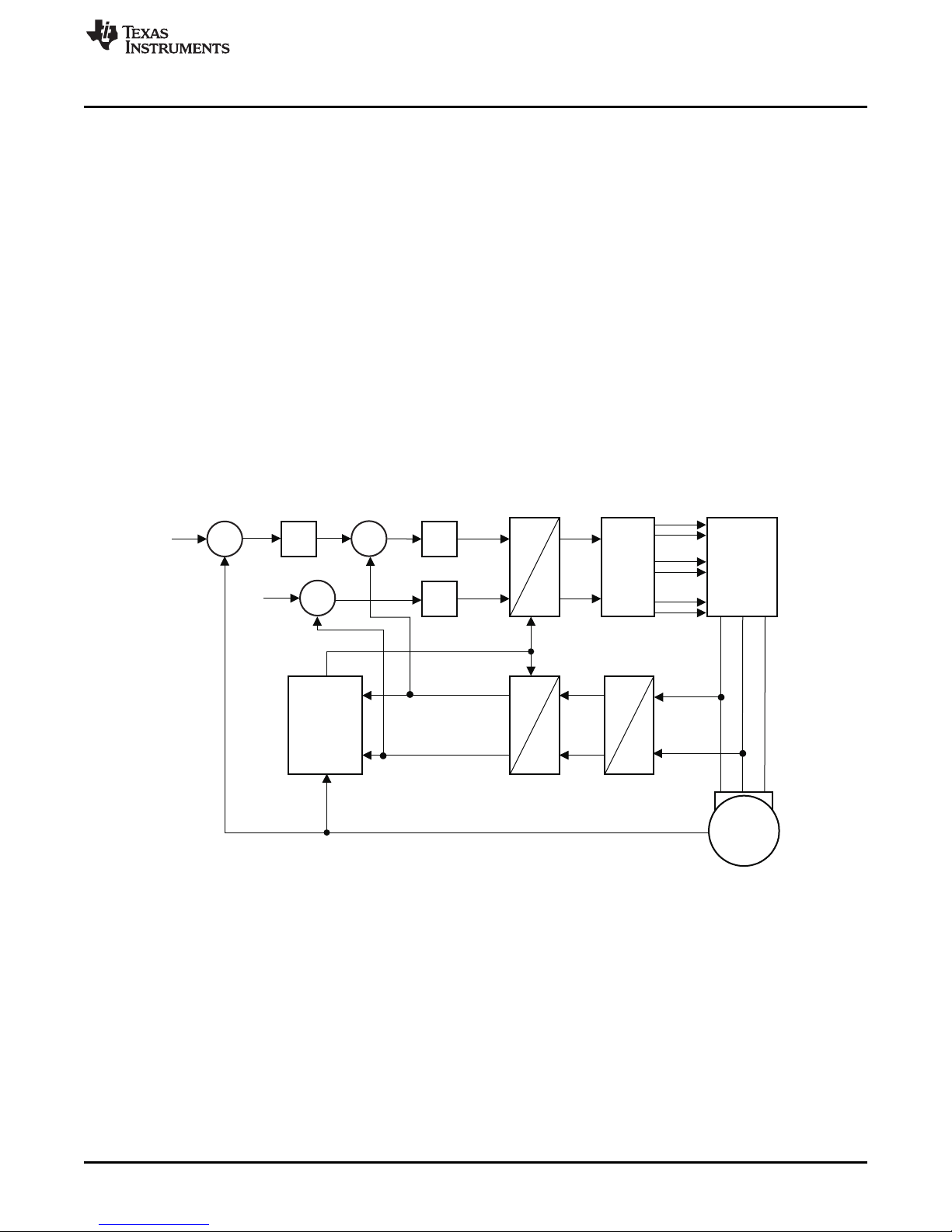
2.3.1 Consistency Between Software Modules and Control Block Diagrams
It is well known that systems and control engineers like to visualize systems or control strategies in the
form of signal flow block diagrams. It makes good sense to separate main functions and to show how
each is interrelated by explicit connection to other functions. Each function should be self-contained, and
its boundaries or interface clearly delineated. A digital motor control system is a good example of this
interrelation of functions. Figure 2 shows a typical signal flow block diagram of an AC induction motor
controlled by a field-oriented control strategy. This is a useful representation, and it is found in many
classical texts on motor control. However, several limitations are evident when attempting to realize this
diagram in software form.
Figure 2. ACI Sensored FOC - System Block Diagram
Software Tools
It is not usually clear how software variables are related to the signal parameters on the diagram, nor
where in the software these parameters can be found and accessed. Moreover, the boundary between
software and hardware is blurred (i.e., where the software controls the on-chip peripheral and where the
peripheral output pins control the external hardware, such as the PWM-to-inverter interface). By adopting
a modular strategy and enforcing some clear definitions, the classic block diagram shown in Figure 2 can
be rearranged and redrawn to reveal a great amount of information about the actual software which is
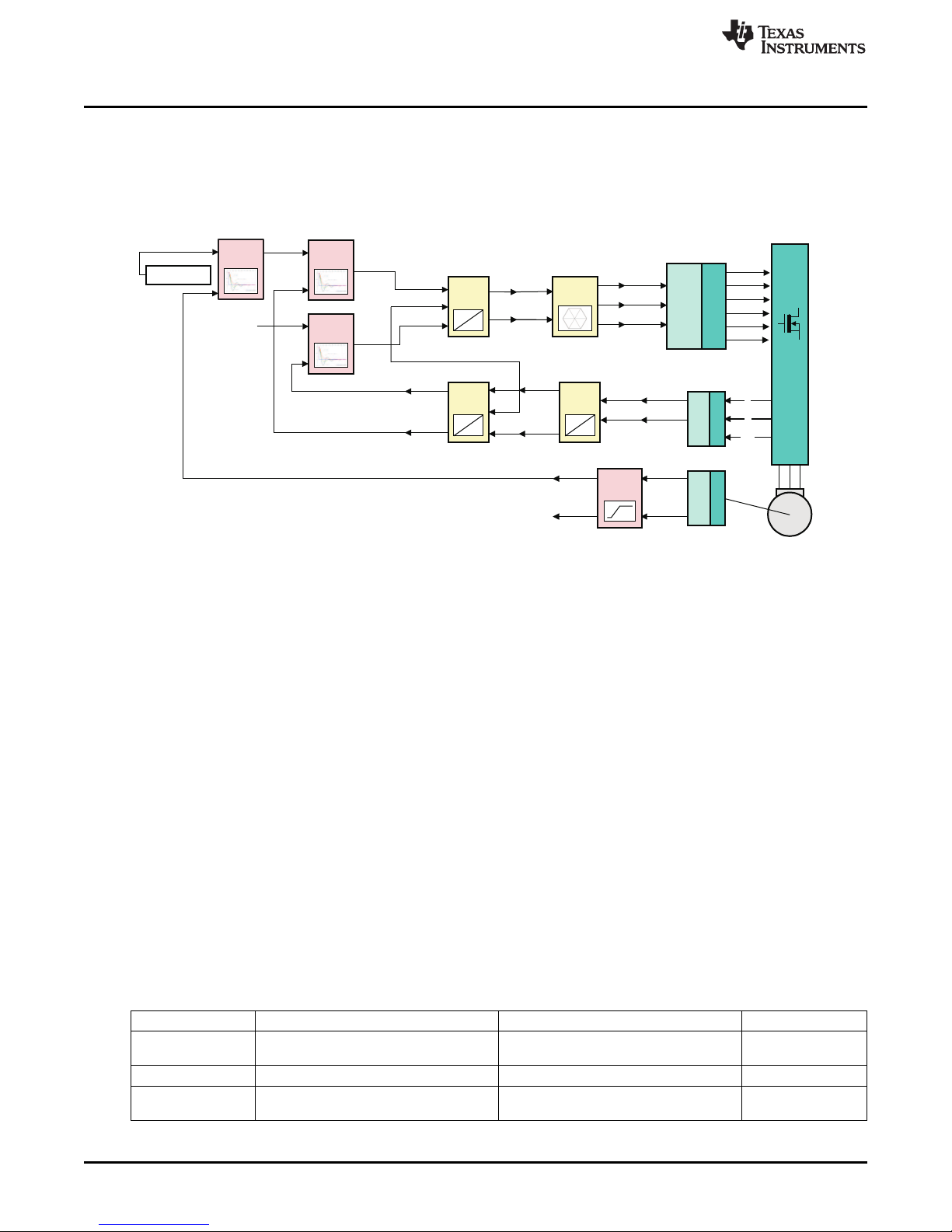
used to implement such a system. This new style of system representation can be seen in Figure 3. The
advantages and features of such a representation will be expanded upon in later sections, but a summary
of key points are given here:
• The system block diagram has a clear one-to-one mapping to the modular system software.
• Each module graphic or block represents a self-contained software function or object of the same
name.
• Input and output terminals of each module correspond exactly to global variables within the software
function.
SPRUGI6–September 2010 TMS320C2000 Motor Control Primer
Submit Documentation Feedback
Copyright © 2010, Texas Instruments Incorporated
7
Page 8
park_D
park_Q
clarke_d
clarke_q
Valpha
Vbeta
Tb
Ta
Tc
Ipark_d
Ipark_Q
Theta
Ipark_q
Mfunc_c1
Mfunc_c2
Mfunc_c3
PWM1A
PWM
DRV
MACRO
PWM1B
PWM2A
PWM2B
PWM3A
PWM3B
EV
HW
3-Phase
Inverter
PMSM
Motor
ADC
DRV
EV
HW
AdcRslt0
AdcRslt1
clarke_a
clarke_b
park_d
PARK
MACRO
CLARKE
MACRO
SVGEN
DQ
MACRO
IPARK
MACRO
theta
watch window
Speed_Ref
PID
MACRO
Iq Reg.
IdRef (=0)
PID
MACRO
Id Reg.
QEP
DRV
EV
HW
QEPA
QEPB
Index
Elec
Theta
Direction
Speed
Speed Rpm
SPEED_FR
MACRO
u_out_q
u_out_d
i_ref_d
I_ref_q
PID
MACRO
Iq Reg.
spd_fdb
Ipark_D
park_q
Ia
Vdc
Ib
Software Tools
www.ti.com
• Modules are categorized (color coded) to clearly designate dependencies on peripherals and target
hardware.
• Connections between modules show data flow via corresponding input/output variables.
• Each module is reusable and has its own documentation explaining usage and instantiation.
Figure 3. ACI Sensored FOC – System Block Diagram Showing Clear One-to-One Mapping to Software
2.3.2 Reusability, Compatibility, and Expandability
Engineering reuse in today’s competitive environment is critical and software modularity is the perfect
vehicle to achieve this, especially in DMC systems. If we examine various motor control systems, it
becomes clear that a large degree of commonality exists between them. The PID regulator, for example,
is useful across all systems. Therefore, if each module is realized only once, but implemented according
to well defined guidelines, then compatibility and predictability can be assured across all modules. Since
this approach allows efficient reusability, efforts which may typically be used to “reinvent the wheel” can be
re-deployed on expanding the module library base for greater functionality and features.
There are several DMC blocks common for 3-phase motor control in general. On the other hand, in most
cases, the difference between a sensored and sensorless system is only one or two modules, e.g., a
position or speed estimator. The remaining modules are again common. Therefore, in keeping with the
reuse philosophy, design efforts can be focused on expanding the library with more robust estimators
which meet various system requirements, rather than recreating entire system infrastructures.
2.3.3 Target Independent Modules and Drivers
Understanding the exact dependencies of a software module is very important. This knowledge is
invaluable during debugging, software porting from one target to another, and on planning a system
commissioning strategy. The modules which are part of the DMC Library (examples of which are shown in
Table 3) are categorized into two main types:
8
• Target (microcontroller) independent (TI)
• Drivers (i.e., target dependent and application configurable)
Table 3. Sample of DMC Module Descriptions and Type Category
Number Module Description Type
1 bldcpwm_drv BLDC PWM driver – uses high-side Drv
2 cap_event_drv Capture input event driver Drv
3 hall_gpio_drv Hall effect interface driver for sensored Drv
TMS320C2000 Motor Control Primer SPRUGI6–September 2010
chopping and fixed on/off for low side
Copyright © 2010, Texas Instruments Incorporated
3-phase BLDC trapezoidal control
Submit Documentation Feedback
Page 9

www.ti.com
Software Tools
Table 3. Sample of DMC Module Descriptions and Type Category (continued)
Number Module Description Type
4 pwm_drv PWM driver (configurable for active Drv
high/low, dead-band, or asm/sym)
5 bdc_pwm_drv Brushed DC-Motor PWM driver Drv
6 qep_theta_drv Quadrature encoder pulse interface driver Drv
with position (theta) as output
7 qep_no_index_drv Quadrature encoder pulse interface driver Drv
without index pulse
8 ileg_vdc Analog to digital conversion drive Drv
9 resolver_drv Position and speed calculations for Drv
resolver sensor
10 data_log Data logging utility – useful for variable Util
graphing in code composer
11 pwm_dac_drv 4-channel DAC driver useful for displaying Util
real-time variables on scope
12 aci_fe Flux estimator for 3-phase induction TI/AC
motor vector control
13 aci_se Speed estimator of the 3-ph induction TI/AC
motor
14 clarke Clark transform – 3-phase to 2-phase TI/AI
(quadrature) conversion
15 comtn_trig Commutation trigger for BLDC sensorless TI/AC
trapezoidal/BEMF/ZC tech.
16 cur_mod Rotor flux position estimator for 3-phase TI/AC
induction motor vector control
17 i_park Inverse park transform – Rotating to TI/AI
stationary reference frame conversion
18 impulse Impulse generator module TI/AI
19 mod6_cnt Modulo 6 counter counts from state 0 TI/AI
through 5 and reset
20 park Park transform – Stationary to rotating TI/AI
reference frame conversion
21 phase_volt_calc 3-phase voltage recontruction function TI/AI
based on PWM duty cycle inputs
22 pid_reg3 Proportional/integral/derivative controller TI/AC
with anti windup feature
23 ramp_gen Sawtooth generator with adjustable gain, TI/AI
frequency and dc offset
24 rmp2cntl Ramp up and ramp down module TI/AI
25 rmp3cntl Ramp down module TI/AI
26 rmp_cntl Ramp up and ramp down module used to TI/AI
control slew rate
27 smopos sliding mode observer for position TI/AC
estimation in sensorless vector drives
28 speed_est Motor speed estimator using the TI/AC
estimated rotor position
29 speed_frq Speed calculator based on frequency TI/AI
measurement – tacho style method
30 speed_prd Speed calculator based on period TI/AI
measurement between events
31 svgen_dq Space vector generator function with TI/AI
quadrature control
32 svgen_mf Space vector generator function with TI/AI
magnitude and frequency control
33 v_hz_profile Volts/hertz profile for induction motor TI/AC
(voltage vs. frequency)
SPRUGI6–September 2010 TMS320C2000 Motor Control Primer
Submit Documentation Feedback
9
Copyright © 2010, Texas Instruments Incorporated
Page 10
Valpha
Vbeta
Tb
SVGEN
DQ
MACRO
Ta
Tc
rmp_freq
rmp_out
RG
MACRO
rmp_offset
rmp_gain
rmp_out
CLARKE
MACRO
clarke_a
clarke_b
Ref
Fdb
Out
PID
MACRO
Spd Reg.
configuration
Kp:
1.0
Ki:
0.02
Kd:
0.003
Max limit:
+0.8
Min limit:
-0.8
configuration
PWM 1/2/3:
Acitive Hi/Lo
PWM Trip:
HI_Z/LO
PWM Mode:
Sym/Asym
PWM Freq:
5-30 kHz
Deadband:
0-20 us
Mfunc_c1
Mfunc_c2
Mfunc_c3
PWM1A
PWM
DRV
MACRO
PWM1B
PWM2A
PWM2B
PWM3A
PWM3B
EV
HW
Software Tools
For convenience, the module graphics throughout the documentation are color coded to help customers
quickly identify a modules dependency within a system. Color designation is as follows:
• Target independent/application independent : TI/AI yellow
• Target independent/application configurable : TI/AC pale red
• Drivers (target dependent/application DRV blue
configurable) :
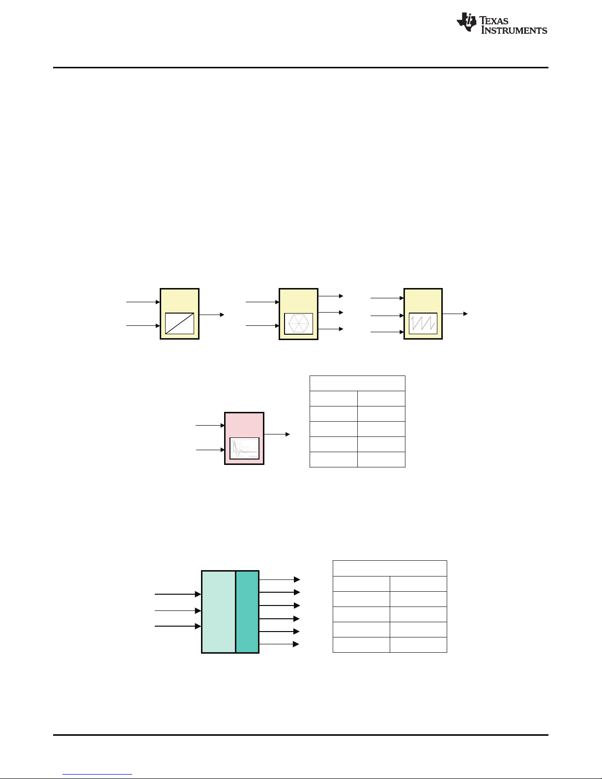
Examples of target independent modules are given in Figure 4 and Figure 5. Target independent modules
do not directly access or modify control or status registers of any on-chip peripherals, i.e., target
microcontroller-specific resources. These modules are dependent only on the CPU core. TI/AI modules
are typically characterized by mathematical type functions (e.g., transforms, matrix operations, waveform
generators, etc.). These functions are fixed and fairly standardized, and do not require configuration,
knowledge of peripherals, or the end application itself. TI/AC modules also do not need knowledge of
device peripherals, but do need to be configured depending on the end application. Examples of these
modules are PID controllers, position/speed estimators, voltage and current models, etc.
www.ti.com
Figure 4. Target and Application Independent Modules - Examples
Figure 5. Target Independent/Application Configurable Modules
On the other hand, driver modules are the interface between software and target microcontroller-specific
peripheral hardware. Examples of such modules are shown in Figure 6. These modules have direct
access to peripheral control and status registers. Using these driver modules or taking them as a
reference, one can easily develop application specific drivers to configure microcontroller peripherals such
as PWMs, ADCs, QEP, CAP etc., as required.
Figure 6. Target Dependent Drive Module
10
TMS320C2000 Motor Control Primer SPRUGI6–September 2010
Copyright © 2010, Texas Instruments Incorporated
Submit Documentation Feedback
Page 11

Dlog 1
Dlog2
Dlog3
Dlog4
DLOG
MACRO
CCS Graph
Windows
PwmDacPointer 4
Scope
Low
Pass
Filter
PwmDacPointer 3
PwmDacPointer 2
PwmDacPointer 1
DAC 1
DAC 2
DAC 4
DAC 3
PWM5A
PWM6A
PWM7B
PWM7A
PWMDAC
MACRO
www.ti.com
2.3.4 Utility/Debug Modules
Utility and/or debug modules are mainly used during the software development and debug process.
Typically they are removed at time of software completion; however they can also be left in the code for
system diagnosis if required during field tests or evaluation. Two examples of these modules are shown in
Figure 7. These modules allow the software designer to probe any of the system variables, and display
them in real time via a scope or a graphical output within Texas Instruments' Code Composer Studio.
The PWMDAC module allows the user to monitor waveforms of software variables through a scope, while
DLOG_VIEW provides a memory buffer with a trigger feature that allows Code Composer to display two
graphical waveforms in real-time. Graphical waveforms are continuously updated via the JTAG debug link
while the customer’s application software continues to run. Both JTAG and the real-time data flow are
non-intrusive to application software running on any devices.
Software Tools
Figure 7. Utility/Debug Modules
2.3.5 Quick Module Evaluation and Testing
Apart from the more obvious benefits of software modularity previously described, some of the same ideas
can be used to facilitate quick module testing or evaluation, i.e., checking how applicable or how a module
performs. Additionally, it becomes easy to test several “what if” scenarios by simply reconnecting modules
and evaluating several alternatives. Figure 8 shows a “module under test” setup where a known input
stimulus is applied. The input stimulus and output response of this module under test can be conveniently
monitored in real time on a scope via the PWMDAC or DLOG utility modules.
Apart from evaluating or confirming operation of a known good software module, this technique is useful
when developing new modules. During debug, input stimulus signals can be swept over the entire input
range to look for boundary condition problems or discontinuities in output response. It should be noted that
this process is valid, provided known good stimulus modules are used as input signals. This technique
allows a software designer to check validity of variable ranges, and to ensure waveform integrity over a
required frequency range and system sampling rates.
SPRUGI6–September 2010 TMS320C2000 Motor Control Primer
Submit Documentation Feedback
Copyright © 2010, Texas Instruments Incorporated
11
Page 12

IPARK
MACRO
Valpha
Vbeta
Tb
SVGEN
DQ
MACRO
Ta
Tc
DacPtr 4
DacPtr 3
DacPtr 2
DacPtr 1
DAC 1
DAC 2
DAC 4
DAC 3
PWMDAC
MACRO
Ipark_d
VdTesting
VqTesting
Angle
Ipark_q
Tb-Tc
Module under test
Graph
Window
Graph
Window
Software Tools
Figure 8. Testing and Evaluating Modules
2.3.6 DMC Library Documentation Support
TI seeks to offer a rich selection of software examples and working systems which are clearly
documented. One area which has received much attention and improvement is the description or
documentation of application software. Through the use of software modularity, it is possible to delineate
and give an unambiguous one-to-one mapping between a system block (signal flow) diagram and the
actual software code in question. This, together with module documentation for each software block,
shows the customer clearly where each piece of software is, what it is doing, and more importantly, the
parameters or variables being passed and executed upon. All TI applications which are part of the
software offering, now consist of module documents and system documents. System documents always
include the system block or signal flow diagram, which among control engineers, remains one of the most
useful communication tools.
www.ti.com
2.3.6.1 Module Level DMC Library Documents
The pdf files included in the library folders provide necessary information regarding the modules. The
outline of the module documents is standard and can be itemized as follows:
• Introduction: Describes the functionality of each module, and provides detailed information about
modules properties such as type, target devices, etc.
• C Interface: Module declaration details, usage, examples etc.
• Technical Background: Mathematical derivation of the module functionality.
Figure 9 shows these library documents and their location in controlSUITE , both in the desktop and in the
C: folders.
12
TMS320C2000 Motor Control Primer SPRUGI6–September 2010
Copyright © 2010, Texas Instruments Incorporated
Submit Documentation Feedback
Page 13

PARK
Description
This transformation converts vectors in balanced 2-phase orthogonal stationary
system into orthogonal rotating reference frame.
Availability
This IQ module is available in one interface format:
1) The C interface version
Module Properties
Type:
Target Devices:
C Version File Names:
math library files for C:
Target Independent, Application Independent
28x Fixed and Floating Point devices
park.h
IQmathLib.h, IQmath.libIQ
Park Variable Transformation
Ds
PARK
MACRO
Alpha
Beta
Sine/Cosine
Qs
www.ti.com
Software Tools
Figure 9. Library Documents and Their Location in controlSUITE
As shown in Figure 10, a target independent transformation module is described and the module
inputs/outputs are shown explicitly in the introduction part. In addition, module type, target devices, and
related files are explained in this section.
Figure 10. Snapshot of Typical Target Independent Module
SPRUGI6–September 2010 TMS320C2000 Motor Control Primer
Submit Documentation Feedback
Copyright © 2010, Texas Instruments Incorporated
13
Page 14

C Interface
Object Definition
The structure of PARK object is defined by following structure definition
typedef struct { _iq Alpha;
_iq Beta;
_iq Angle;
_iq Ds;
_iq Qs;
} PARK;
typedef PARK *PARK_handle;
//Input: stationary d-axis stator variable
//Input: stationary q-axis stator variable
//Input: rotating angle (pu)
//Output: rotating d-axis stator variable
//Output: rotating q-axis stator variable
Item
Name
Description
Format
Range(Hex)
Inputs
Alpha
Direct axis(d) component of the
transformed signal
GLOBAL_Q
80000000-7FFFFFFF
Beta
Quadrature axis(q) component of the
transformed signal
GLOBAL_Q
80000000-7FFFFFFF
Angle
Phase angle between stationary and
rotating frame
GLOBAL_Q
80000000-7FFFFFFF
(0-360 degree)
Sine
Sine of the phase angle between
stationary and rotating frame
GLOBAL_Q
80000000-7FFFFFFF
Cosine
Cosine of the phase angle between
stationary and rotating frame
GLOBAL_Q
80000000-7FFFFFFF
Outputs
Ds
Direct asix (D) component of
transformed signal in rotating
reference frame
GLOBAL_Q
80000000-7FFFFFFF
Qs
Quadrature axis(Q) component of
transformed signal in rotating
reference frame
GLOBAL_Q
80000000-7FFFFFFF
GLOBAL_Q valued between 1 and 30 is defined in the IQmathLib.h header file.
Software Tools
Following the module description, all the necessary information is provided for C interface of the DMC
module, the introduction of which is shown below in Figure 11. This section explains the structure of the
module object; name, description, and format of the module input and outputs. It also explains special
constants and data types, module initialization and usage, and pseudo code providing the information
about the module usage.
www.ti.com
Figure 11. Snapshot of First Part of C Interface Section
In the last section, theoretical background and mathematical derivations of the equations (if applicable) are
provided to the user as shown in Figure 12. This section helps the user to understand the philosophy
behind the module and allow the user to customize it properly.
14
TMS320C2000 Motor Control Primer SPRUGI6–September 2010
Copyright © 2010, Texas Instruments Incorporated
Submit Documentation Feedback
Page 15

q
Q
lq
lq cos• θ
IQ
θ
θ
ld sin• θ
θ
θ
ld cos• θ
lq sin• θ
dld
ID
D
Technical Background
Implements the following equations:
This transformation converts vectors in 2-phase orthogonal stationary system into the
rotating reference frame as shown in figure below:
The instantaneous input quantities are defined by the following equations:
(
)
(
)
sin
sin / 2
id I t
iq I tωω π
= ×
= × +
cos sin
sin cos
ID Id Iq
IQ Id Iq
θ θ
θ θ
= × + ×
= − × + ×
www.ti.com
Software Tools
Figure 12. Snapshot From the Theoretical Background Section (need equation)
2.3.7 DMC Library Optimization
There are several ways to optimize motor control systems for performance in terms of memory
consumption and CPU cycles required to achieve the given task. TI suggests the following options to
optimize the overall system performance:
• Use of the optimization levels via the –o switch on the compiler
• Use of inlining as a technique to increase speed of execution
• Transforming functions in to inline code via macro expansion
When a function is called separately, the function call must call the code at the appropriate address,
followed by a return statement when the function execution is completed. In addition, there is some
overhead associated with setting up a stack frame. In the case of a small function, this call and return
overhead may be significant, compared to the size of the function itself. In addition, when a function is
inlined, the compiler can optimize the function in context of the calling code.
Another optimization is sometimes possible: to turn the function into a macro expansion. This allows the
compiler to optimize further under certain circumstances and produces less code, and consumes fewer
cycles to execute. The disadvantage of this method is the code size increase if multiple expanded macros
are implemented. However, for single motor control, both size and cycle wise macro modules have
superiority to earlier versions where the code size becomes comparable for dual motor operation. One
must note that the number of instruction cycles is much lower in any case.
Unlike the DMC Library version in Legacy, the modules in controlSUITE are written in the form of macros
for optimization purposes (refer to Optimizing Digital Motor Control Libraries, SPRAAK2, for more details
at TI website). It is reported that the macro versions of the DMC library let the system run 2-3 times more
efficient than non-optimized version in Legacy. The macros are defined in the header files. The user can
open the respective header file and change the macro definition, if needed. In the macro definitions, there
should be a backslash ”\” at the end of each line as shown below which means that the code continues in
SPRUGI6–September 2010 TMS320C2000 Motor Control Primer
Submit Documentation Feedback
Copyright © 2010, Texas Instruments Incorporated
15
Page 16

#define PARK_MACRO (v) \
\
v
.Ds = _IQmpy(v.Alpha,v.Cosine) + _IQmpy(v.Beta,v.Sine); \
v
.Qs = _IQmpy(v.Beta,v.Cosine) - _IQmpy(v.Alpha,v.Sine);
#endif // __PARK_H__
/*============================================================================
File name: PARK.H (IQ version)
Originator: Digital Control Systems Group
Texas Instruments
Description: Header file containing constants, data type, and macro definitions
============================================================================*/
#ifndef __PARK_H__
#define __PARK_H__
typedef struct { _iq Alpha; // Input: stationary d-axis stator variable
_iq Beta; // Input: stationary q-axis stator variable
_iq Angle; // Input: rotating angle (pu)
_iq Ds; // Output: rotating d-axis stator variable
_iq Qs; // Output: rotating q-axis stator variable
_iq Sine;
_iq Cosine;
} PARK;
typedef PARK *PARK_handle;
/*---------------------------------------------------------------------------Default initalizer for the PARK object.
----------------------------------------------------------------------------*/
#define PARK_DEFAULTS { 0, \
0, \
0, \
0, \
0, \
0, \
0, \
}
/*----------------------------------------------------------------------------
PARK Transformation Macro Definition
----------------------------------------------------------------------------*/
for the PARK.
A typical module declaration and macro definition
Software Tools
the next line. Any character including invisible ones like “space” or “tab” after the backslash will cause
compilation error. Therefore, make sure that the backslash is the last character in the line. In terms of
code development, the macros are almost identical to C function, and the user can easily convert the
macro definitions to inline C functions. As an example, the park transformation macro definition is shown
below.
www.ti.com
Figure 13. A Typical Module Declaration and Macro Definition
2.4 Incremental Build Methodology
Irrespective of how much planning has gone into a system engineering project, the chances are that the
final (or complete) system will not work the first time, usually some subtle (or not) target dependency or
requirement has been overlooked. This is normal engineering, especially in the case of software
16
development, and if not anticipated ahead of time, can become a frustrating and time consuming disaster.
To prevent this, TI’s DMC Library system software comes prepackaged within a framework, incorporating
various system build levels or debug steps as part of the normal system software flow. A customer can
move from a current build level to any other build level very quickly and without risk of losing configuration
TMS320C2000 Motor Control Primer SPRUGI6–September 2010
Copyright © 2010, Texas Instruments Incorporated
Submit Documentation Feedback
Page 17

www.ti.com
or run-time information related to previous build levels. This allows a customer to commission system
software in a step-by-step manner, and at each step validate key vital signs before moving on. The
number of build levels may vary depending on final system complexity and the type of control strategy
used. It is important to note that regardless of the number of build levels used in the reference system, this
framework is provided by TI as guidance and becomes a common point of reference in cases where
customer trouble shooting necessitates interaction with TI customer support engineers.
Incremental system build levels are supported by frameworks with various configurations of interconnected
modules. Frameworks also provide invaluable skeletons for customers to modify or customize as required
to suit their own target system requirements, forming an excellent starting point.
To better understand the philosophy and details of the incremental build approach, a typical motor control
case, a permanent magnet synchronous motor, will be used to step through the various commissioning
phases. The system shown in is the final build of a sensored PMSM project. The subsequent block
diagrams (Figure 14 to Figure 17) show examples of typical steps used to get to a solidly working final
system.
2.4.1 Check System Vital Signs - Build Level 1
Figure 14 shows the module configuration of build level 1. Although the first is the simplest build, it is
perhaps the most important one since many system fundamentals can be validated here. Build 1 removes
main external connections (power hardware, motor, feedback circuitry, etc.) and allows a customer to
focus on:
• Code compiling/linking using a Code Composer Studio (CCS) project
• Invoking and downloading to the CCS debug environment
• Setting up or importing a CCS workspace
• Running code in real-time mode
• Ensuring the hardware is functioning correctly
Assuming the above check list is correct, some key system vital signs can now be validated:
• Check Interrupt Trigger: The sensored PMSM project, like most other DMC systems, is an interrupt
driven, time sampled system, meaning that the modules shown in Figure 14 are executed and updated
on every interrupt. The Isr_Ticker, a software variable in the interrupt subroutine (ISR) behaves like a
counter, and it is updated when an interrupt is triggered and the code in the ISR is executed. In order
to confirm that the ISR is being triggered at each selected event, this variable can be added to the
watch window to see whether or not it is updating.
• Testing some target independent modules: Validating both the stimulus waveforms (output of
RAMP_GEN), and output of SVGEN via the PWMDAC utility or graph windows confirms system
interrupts are being generated and the main ISR is executing correctly. At this stage, the RAMP_GEN
function can be manipulated via CCS watch window to change its frequency and to see the
corresponding changes on the waveforms.
• PWMDAC utility test: To monitor internal software variables and signal waveforms in real time PWM
DACs are very useful tools. Present on the HVDMC board are PWM DAC’s (PWM5-7) which are
connected to external low pass filters to generate the waveforms. A simple 1st–order low-pass filter RC
circuit is placed on the board to filter out the high frequency components. The selection of R and C
value (or the time constant, t) is based on the cut-off frequency (fc). For example, R=1.8kΩ and
C=100nF, it gives fc = 884.2 Hz. This cut-off frequency has to be below the PWM frequency. Refer to
Using PWM Output as a Digital-to-Analog Converter on a TMS320F280x, SPRAA88A for more details.
• Check PWM outputs and verify PWM configuration: In addition, it is important to verify that the
space vector signals (Ta, Tb, and Tc) are correctly modulating the PWM outputs. This is easily
checked by filtering or suppressing the high frequency carrier (typically 10–20 kHz) at the PWM output
pins by a simple RC filter with approximately 1 kHz cutoff. The filtered waveforms should then
resemble the unmodulated ones seen at variables Ta, Tb, and Tc using the PWMDAC module. We
now have a working forward path for the PMSM controller running in open loop, and are ready to
connect the power inverter hardware and motor.
• Inverter test: After verifying SVGEN module, the PWM software module and the 3-phase inverter
hardware are tested by looking at the low pass filtered PWM outputs. For this purpose, if using the
external DC power supply, gradually increase the DC bus voltage and check the Vfb-U, V and W test
points using an oscilloscope; or if using AC power entry slowly change the variac to generate the DC
Software Tools
SPRUGI6–September 2010 TMS320C2000 Motor Control Primer
Submit Documentation Feedback
17
Copyright © 2010, Texas Instruments Incorporated
Page 18

SVGEN
DQ
MACRO
IPARK
MACRO
Valpha
Vbeta
Tb
Ta
Tc
Ipark_d
VdTesting
VqTesting
Theta
Ipark_q
rmp_freq
rmp_out
RG
MACRO
rmp_offset
rmp_gain
RC
MACRO
trgt_value
set_value
eq. flag
watch window
Mfunc_c1
Mfunc_c2
Mfunc_c3
PWM1A
PWM
DRV
MACRO
PWM1B
PWM2A
PWM2B
PWM3A
PWM3B
EV
HW
Dlog 1
Dlog 2
Dlog 3
Dlog 4
DLOG
MACRO
Tb
Ta
Tc
DacPtr 4
DacPtr 3
DacPtr 2
DacPtr 1
DAC 1
DAC 2
DAC 4
DAC 3
PWMDAC
MACRO
Tb
Ta
Tc
Tb-Tc
C
R
Software Tools
bus voltage. The inverter phase voltage dividers and waveform monitoring filters enable the generation
of the waveform. This circuit is used to observe the low-pass filtered phase voltage waveform to make
sure that the inverter stage is working properly.
Figure 14. Build Level I - Checking Vital Signs
2.4.2 Open Loop Motor Operation - Build Level 2
In this level, the motor is connected to the inverter and the motor is run open loop. In this level, the items
below will be verified:
• Open loop test: This is the first level that the motor is connected and run open loop. The user expects
to set VdTesting (a software variable which is supposed to generate the Vd and indirectly id
component of the stator current that produce flux) to zero since the flux will already be generated by
magnets, and apply non-zero VqTesting to generate torque. At this point, the motor should spin
smoothly, indicating that the inverter hardware is functioning properly. Since the field is not perfectly
oriented and the current loops are not closed, it is not recommended to load the motor or run it various
speeds at this level in order not to lose synchronization or stall the motor. Second, the test should
initially be run under modest dc bus level for safety reasons. Once the user confirms that everything
performs as expected, then the dc bus can be increased to the rated value. During the open loop tests,
VqTesting, SpeedRef (speed reference) and DC Bus voltages should be adjusted carefully for PM
motors so that the generated Bemf is lower than the average voltage applied to motor winding. This
will prevent the motor from stalling or vibrating. Therefore, tuning might be needed for VqTesting and
SpeedRef for different motors.
• Verify and calibrate the ADCs measurements and check ADC configuration: It is necessary to
make sure that the scaling factors of ADC measurements (voltage, current etc.) are set correctly, and
that the dc offset caused by the passive component tolerances is minimized. Note especially that low
power motors draw low amplitude current after closing the speed loop under no-load. The performance
of the sensored/sensorless control algorithms becomes prone to phase current offset which might stop
the motor or cause unstable operation. Therefore, the phase current offset values need to be
minimized at this step. Since the current drawn by the motor is non-zero, the user should be able to
monitor the current waveforms both from PMWDAC and CCS graph windows. If the current waveforms
cannot be monitored even though the motor spins, then the ADC configuration settings should be
double checked (such as channel selection, ADC system clock enable, etc.).
• Check the Clarke transform & current waveforms: With the motor running in a stable state, it is
possible to validate the current measurement feedback path. The peripheral driver ILEG2_DRV helps
the user configure ADC and measure 2 inverter leg currents and reconstructs the motor phase
currents. The 120o phase currents are transformed to 90o quadrature currents by the CLARK
transform module. Using PWMDAC or graph window, the shape, phase and quality of the current
waveforms can be inspected. The Clarke alpha component should be leading Clarke beta if everything
is set correctly, otherwise the user will not be able to run the next level and close the current loop.
www.ti.com
TMS320C2000 Motor Control Primer SPRUGI6–September 2010
18
Copyright © 2010, Texas Instruments Incorporated
Submit Documentation Feedback
Page 19

park_D
park_Q
clarke_d
clarke_q
Valpha
Vbeta
Tb
Ta
Tc
Ipark_d
VdTesting
VqTesting
Theta
Ipark_q
rmp_freq
rmp_out
rmp_offset
rmp_gain
trgt_value
set_value
eq. flag
watch window
Mfunc_c1
Mfunc_c2
Mfunc_c3
PWM1A
PWM
DRV
MACRO
PWM1B
PWM2A
PWM2B
PWM3A
PWM3B
EV
HW
Dlog 1
Dlog 2
Dlog 3
Dlog 4
DLOG
MACRO
Tb
Ta
Tc
DacPtr 4
DacPtr 3
DacPtr 2
DacPtr 1
DAC 1
DAC 2
DAC 4
DAC 3
PWMDAC
MACRO
Tb
Ta
Tc
Tb-Tc
R
3-Phase
Inverter
ADC
DRV
EV
HW
Ia
Vdc
Ib
AdcRslt0
AdcRslt1
clarke_a
clarke_b
park_d
park_q
PARK
MACRO
CLARKE
MACRO
SVG
END
QMACRO
IPARK
MACRO
RG
MACRO
RC
MACRO
theta
watch window
Speed_Ref
Motor
PMSM
C
www.ti.com
Software Tools
Figure 15. Build Level II - Inverter Test and ADC Calibration
2.4.3 Closed Current Loop Operation - Build Level 3
Assuming the previous section is completed successfully, this section verifies the dq-axis current
regulation performed by PID_REG3 modules, QEP drv and speed measurement modules.
• Current regulator (PID modules) test and tuning: 3-phase motor control mainly consists of two main
control loops: a current loop and a speed loop. At this level, current control PIDs will be tested and
tuned if needed. After a successful tuning, the user should make sure that the feedback currents
precisely follow the Id and Iq current references. While testing the PIDs, the dc bus voltage should not
be too low; otherwise the outputs of the PID modules saturate which might introduce unwanted glitches
on the current waveforms or unstable operation. Once a stable set of PID coefficients is found, the
transient response of the PIDs should be examined by changing Iq and Id references (IqRef and IdRef
respectively). This has to be repeated for various load and speed conditions. Most of the time a single
set of coefficients does not perform well at all operating points; therefore an operating point dependent
PID coefficient look-up table may be used to improve performance.
• QEP drv test: Build 3 also implements the angular position sensor feedback path, based on the QEP
driver module which outputs both the mechanical and electrical angles. The optical position sensor and
QEP interface driver are operating correctly when, while the motor is spinning, variable theta_elec can
be viewed on the scope. Its output waveform should correspond in shape to the stimulus theta angle
generated by the RAMP_GEN module. This indicates that position information is being measured
correctly.
• Speed measurement module test: The speed measurement module, SPEED_FRQ, is in the
feedback path and can also be validated at this stage. The speed measurement is dependent on motor
shaft rotation, and the SPEED_FRQ module is driven from the theta_mech output of QEP module.
Since its output value should be constant, i.e. the motor is running at constant synchronous speed, the
calculated speed, speed_frq, can be viewed via a watch window instead of on the scope. The
RAMP_GEN frequency can be increased slowly up or down to check whether the speed measurement
varies appropriately.
• Calibration angle detection: In level 3, a simple calibration angle detection subroutine is added into
the code to measure the initial angle offset. This is necessary because the exact rotor position
information is needed for precise field orientation. The detected offset angle is basically the angle
between the locked rotor (zero) position and the position where the first index signal is received.
SPRUGI6–September 2010 TMS320C2000 Motor Control Primer
Submit Documentation Feedback
Copyright © 2010, Texas Instruments Incorporated
19
Page 20

park_D
park_Q
clarke_d
clarke_q
Valpha
Vbeta
Tb
Ta
Tc
Ipark_d
Ipark_Q
Ipark_D
Theta
Ipark_q
rmp_freq
rmp_offset
rmp_gain
trgt_value
set_value
eq. flag
Mfunc_c1
Mfunc_c2
Mfunc_c3
PWM1A
PWM
DRV
MACRO
PWM1B
PWM2A
PWM2B
PWM3A
PWM3B
EV
HW
3-Phase
Inverter
PMSM
Motor
ADC
DRV
EV
HW
Ia
Vdc
Ib
AdcRslt0
AdcRslt1
clarke_a
clarke_b
park_d
park_q
PARK
MACRO
CLARKE
MACRO
SVGEN
DQ
MACRO
IPARK
MACRO
RG
MACRO
RC
MACRO
theta
watch window
Speed_Ref
PID
MACRO
Iq Reg.
IdRef (=0)
IqRef
watch window
PID
MACRO
Id Reg.
QEP
DRVEVHW
QEPA
QEPB
Index
Elec
Theta
Direction
Speed
Speed Rpm
SPEED_FR
MACRO
u_out_q
u_out_d
i_ref_d
i_ref_q
Software Tools
Figure 16. Build Level III - Closed Current Loop Test
2.4.4 Closed Speed Loop Operation - Build Level 4
In this level, the speed loop will be closed in addition to the current loops regulating stator current d-q
components and use the actual rotor position. This section verifies the speed PID and FOC based on
actual rotor position. The basic sensored, field-oriented control of PMSM motor implementation will be
done once this step is completed successfully.
• Torque control: If the user is interested in “torque only” control, the previous scheme allows the user
control the torque as long as the actual rotor position sensed by the QEP drv is fed to the Park and
IPark transforms. The amount of the load determines the speed of the motor at a given torque
reference since the torque control guarantees constant torque production but cannot control the speed
directly.
• Speed control and speed PID tuning: If it is intended to control both speed and the torque, then the
speed loop should be closed as given in the block diagram of level 4. The reference speed adjusted by
the user is compared to the speed feedback and then the error is compensated by speed PID module
which needs to be tuned at this level. The output of the speed PID is connected to another PID
regulating Iq (stator current torque generating component), and the system increases or decreases the
torque generation depending on the actual speed level vs speed reference. For example, when the
system is loaded, motor speed tends to reduce and the system immediately increase the torque
generation to handle the applied load and indirectly keep the speed at the reference level. Once the
speed PID is tuned at a certain operating point, the user needs to examine the robustness of the
speed loop under various torque/speed levels, step load or any other torque/speed profile applied to
user’s system.
• Now, the actual rotor position is used: It was confirmed in build level 3 that position information
(both electrical and mechanical) was correctly appearing at the outputs of the QEP drive module. In
build level 4, the simulated angle provided by RAMP_GEN is no longer needed. This can now be
replaced by the actual measured electrical angle, theta_elec, which is used as angular position
feedback for the Park and inverse Park transforms.
• Soft-switches helps to manage control loops: The latest incremental build levels are supported by
loop switches (a software variable in the code, lsw) to manage the loops. For instance, when lsw=0,
the rotor is locked to the initial rotor position which is essential for sensored applications. Afterwards,
the lsw is set to 1 to close the current loops which help the motor start up smoothly. This is often
needed for sensorless applications because the algorithms need some time to converge to the actual
position/speed value. Finally, lsw is set to 2 in order to close the speed loop which let the customer
20
control speed accurately and realize field orientation.
TMS320C2000 Motor Control Primer SPRUGI6–September 2010
Copyright © 2010, Texas Instruments Incorporated
www.ti.com
Submit Documentation Feedback
Page 21

park_D
park_Q
clarke_d
clarke_q
Valpha
Vbeta
Tb
Ta
Tc
Ipark_d
Ipark_Q
Ipark_D
Theta
Ipark_q
Mfunc_c1
Mfunc_c2
Mfunc_c3
PWM1A
PWM
DRV
MACRO
PWM1B
PWM2A
PWM2B
PWM3A
PWM3B
EV
HW
3-Phase
Inverter
PMSM
Motor
ADC
DRV
EV
HW
Ia
Vdc
Ib
AdcRslt0
AdcRslt1
clarke_a
clarke_b
park_d
park_q
PARK
MACRO
CLARKE
MACRO
SVGEN
DQ
MACRO
IPARK
MACRO
theta
watch window
Speed_Ref
PID
MACRO
Iq Reg.
IdRef (=0)
PID
MACRO
Id Reg.
QEP
DRVEVHW
QEPA
QEPB
Index
Elec
Theta
Direction
Speed
Speed Rpm
SPEED_FR
MACRO
u_out_q
u_out_d
i_ref_d
i_ref_q
PID
MACRO
Iq Reg.
spd_fdb
/
/
/ , ( 2 )
/ , ( / )
pu base
pu base
pu base base base
pu base base base base
I I I
w w w w f
V w
p
=
=
= =
Y = Y Y Y =
www.ti.com
Figure 17. Build Level IV - Closed Speed Loop Test / FOC
2.5 PU System Model and Base Values
In electrical engineering, a per-unit system is the expression of system quantities as fractions of a defined
base unit quantity. Calculations are simplified because quantities expressed as per-unit (between -1 and
+1) are the same regardless of the voltage, current etc level. Advantages of using the pu system for motor
control applications include:
• Once the base values are initialized in the code, the code will handle the rest and the parameter
dependency will be minimized.
• Migrating to a new custom design system will be as easy as modifying the base values.
• For fixed point devices, pu system allows the user to reduce the amplitude of the variables in order to
get a fractional part with a maximum precision.
Conversion of per-unit quantities to volts, ohms, or amperes requires knowledge of the base that the
per-unit quantities were referenced to. In the TI DMC systems, the base values are selected as the
maximum measurable quantity of the peak of phase voltage, current etc. by the ADC. This is directly
related to the current and voltage sensing circuits and the voltage dividers used to down-scale the actual
voltage or current quantities to ADC input voltage range, which is typically 3 to 3.3V. Later, the measured
voltage by ADCs will be converted to put quantity in the code. The calculation of the pu values can be
formulated as:
Software Tools
SPRUGI6–September 2010 TMS320C2000 Motor Control Primer
The selection of the base quantities is relative and can be any appropriate value as long as it is consistent
within the whole system. For instance, assuming that the peak of the maximum measurable phase current
is 20A on a DMC kit, the base current value can be selected as 20 where ±1pu represents ±20A in the
code.
Submit Documentation Feedback
Copyright © 2010, Texas Instruments Incorporated
21
Page 22

+20A
-20A
Current
Sensing
cct
3.3 V
0 V
12-Bit
ADC
0
DMC
System
(pu)
+1.0
-1.0
2
12
Software Tools
Similarly, the base voltage can be selected as the peak of maximum measurable phase voltage in the
system. Assuming that the dc bus voltage is 400V, base voltage is selected as 400V/√3.
2.6 DMC Systems: Legacy VS controlSUITE
There are basically two separate TI DMC systems offering similar solutions for motor control with minor
differences. These differences can be summarized as:
• controlSUITE supports Piccolo (2803x, fixed point) and Delfino (2833x, floating point) whereas Legacy
supports 280x and 281x (both fixed point).
• In controlSUITE the DMC Library modules are optimized macros whereas legacy modules are regular
C functions typically 2-3 times less efficient.
• The recent TI DMC updates are announced through controlSUITE since 2010.
• Legacy is motor control specific whereas controlSUITE is more comprehensive system covering almost
all C2000 based applications.
The DMC projects in the Legacy and ControlSUITE are given in the table below:
www.ti.com/c2000dmc#dmc
www.ti.com
Table 4. Projects in controlSUITE and Legacy
Motor Type Description Legacy controlSUITE
3-ph ACI Sensored – Tacho i/p 281x 2803x
Scalar Control / SVPWM 280x
3-ph ACI Sensored – Tacho or Encoder 281x 2803x
Field Oriented Control / 280x
SVPWM
3-ph ACI Sensorless – Direct Flux 281x 2803x
3-ph PMSM Sensored – Incremental 281x 2803x
3-ph PMSM Sensorless – Sliding Mode 281x 2803x
3-ph PMSM Sensored – Incremental 281x 2803x
3-ph PMSM Sensored – Resolver 281x TBD
3-ph BLDC Sensored – Hall Effect Sensors 281x 2803x
3-ph BLDC Sensorless – BEMF Sensing 281x 2803x
Estimator
Field Oriented Control / 280x 2833x
SVPWM
Encoder
Field Oriented Control / 280x
SVPWM
Observer
Field Oriented Control / 280x 2833x
SVPWM
Encoder
Position Control / SVPWM 280x
Field Oriented Control / 280x
SVPWM
Trapezoidal Control 280x
Trapezoidal Control 280x
22
TMS320C2000 Motor Control Primer SPRUGI6–September 2010
Copyright © 2010, Texas Instruments Incorporated
Submit Documentation Feedback
Page 23

www.ti.com
Table 4. Projects in controlSUITE and Legacy (continued)
Motor Type Description Legacy controlSUITE
3-ph BLDC Sensorless – Sinusoidal - 2803x
Control
Field Oriented Control /
SVPWM
Brushed DC Sensored – QEP 281x Q410
Position and speed control 280x
Stepper Motor Sensorless – Discrete Angle 280x Q410
Est.
Position and Speed Control
2.6.1 More About controlSUITE
controlSUITE™ is the content and content management tool for C2000™ development. It includes a
comprehensive suite of software that significantly decreases development time and accommodates
different experience levels and programming preferences. It is also a one-stop shop for everything needed
for C2000 system development.
controlSUITE’s main features include:
• controlSUITE desktop graphical navigation tool
• Manual or auto update, to insure synchronization with latest content
• Devices: first-level device initialization, system tasking, and example projects
• Libraries: foundational libraries and utilities for math, DSP, IQMath, CLA, floating point, flash, boot, and
specific applications
• Kits: Entry level to application specific full voltage reference designs, including open tooled hardware,
GUIs, system guides, and CCStudio projects
• Direct Links to: application notes, datasheets, user’s guides
• Training: forums, videos, on-line, in-person, and self-paced workshops
Software Tools
Figure 18. controlSUITE Desktop Graphical Navigation Tools
SPRUGI6–September 2010 TMS320C2000 Motor Control Primer
Submit Documentation Feedback
23
Copyright © 2010, Texas Instruments Incorporated
Page 24

Software Tools
2.7 System Level DMC Documentation Support
In addition to the DMC Library documents detailed in the previous sections, all C2000 motor control
projects are supported by a rich set of collateral to shorten the development time. These documents
basically provide information about the motor type used in the project, control theory (e.g. FOC,
trapezoidal control) system overview, hardware configuration, incremental build levels, hardware
components, GUI related documents etc.
2.7.1 Quickstart Guide and Graphical User Interface (GUI)
In controlSUITE™, an open source graphical user interface is designed for sensorless HVDMC projects so
that the users can visually and quickly evaluate the DMC kit and software without having to learn and
configure the underlying project software or install CCS. Note that the GUI is not a development
environment but intended for demonstration purposes only. The GUI supports all three kinds of motors
(ACI, PMSM, and BLDC). The HVDMC kit ships with both a Piccolo™ F28035 and a Delfino™ F28335
controlCARD. Only the F28035 card is pre-flashed with the code that enables interface to this GUI. The
flashed code is optimized for running sensorless FOC on ACI and PMSM motor and sensorless
trapezoidal control on a BLDC motor that are available from the TI website. Note that the performance of
the motor with the flashed image is not a metric of quality of control and performance levels achievable
using the TI DMC library. The GUI allows the user to select the motor type, visually inspect some
waveforms (e.g., current, voltage, back-emf , etc.), numerically watch bus voltage, estimated speed, set
the reference speed, and change the graph update rate and graph scale. A snapshot of GUI is shown in
Figure 19.
Figure 19. Graphical User Interface for Motor Control
www.ti.com
The GUI exe file, flash image, and related files can be found in Desktop - Kits - Folders - Example GUI, or
at the direct path of:
C:\ti\controlSUITE\development_kits\HVMotorCtrl+PfcKit_v1.3\~GUI
2.7.2 DMC System User Guides
The system user guide is the most critical document explaining the system overview, applied theory,
hardware configuration, and incremental build levels. All motor control projects have a user's guide which
includes:
• Motor Types: In this section electromechanical structure of the motor used in the project is introduced
briefly. Synchronous / asynchronous operation, advantages of the particular motor type, the industrial
areas where the motor type fits, etc., are briefly discussed.
24
TMS320C2000 Motor Control Primer SPRUGI6–September 2010
Copyright © 2010, Texas Instruments Incorporated
Submit Documentation Feedback
Page 25

www.ti.com
• Control Theory: In this section the theory of the motor control is explained both verbally and
mathematically. The philosophy behind the motor control type (e.g., FOC), benefits of the control type,
typical applications, technical background, block diagrams and basic scheme are discussed in this
section.
• System Overview: A brief summary of the DMC modules used in the project, some benchmark
quantities like number of instruction cycles at the modular and system level, the size of the program,
and data memory necessary for each project are given in this section. System features such as
development environment, target controller, switching frequency, ISR source, used peripherals and
mapping, system level drawings and software flow are also given here.
• Hardware Configuration: In this section a list of check list is provided to the user to make sure that
the hardware platform is ready to run. The list includes basic instruction regarding the jumper setting,
supply, motor, and sensor connections, switch state, etc.
• Incremental Build Levels: As discussed in the previous sections, the DMC system is gradually built
up in order for the final system can be confidently operated. A number of phases of the incremental
system build are designed to verify the major software modules used in the system. The details of
each level and related block diagrams are given in this section.
These can be found in controlSUITE Desktop - Kits - Documentation or directly:
C:\ti\controlSUITE\development_kits\HVMotorCtrl+PfcKit_v1.3\HVPM_Sensored\~Docs
Or for Legacy at:
C:\tidcs\DMC\c28\v32x\sys\pmsm3_1_280x\doc
2.7.3 Hardware Guide and How to Run Guides
The hardware guide describes the target kit contents and hardware details, and explains the functions and
locations of jumpers and connectors present on the board. This document supersedes all the documents
available for the kit. The items discussed in this document include:
• Kit content
• Kit (electrical) features
• Functionality of the each block on the board
• Powering the board
• Boot modes
• GUI connection
• Ground levels and safety
• Hardware resource settings
• Jumpers and connectors, etc.
The “How to Run” guide explains the steps needed to run the target kit with the software supplied through
controlSUITE. The list of document content is given below:
• Hardware configuration
• Motor control experiment hardware setup instructions
• Software setup for the kit projects
• Set up Code Composer Studio
• Configuring a project
• Setup watch window and graphs
Both of the documents can be found in controlSUITE or directly:
C:\ti\controlSUITE\development_kits\HVMotorCtrl+PfcKit_v1.3\~Docs
Software Tools
2.7.4 Hardware Development Package
In controlSUITE, a hardware development package is prepared for each hardware platform including:
• Bill of materials
• Schematics and layouts
• Gerbers
SPRUGI6–September 2010 TMS320C2000 Motor Control Primer
Submit Documentation Feedback
25
Copyright © 2010, Texas Instruments Incorporated
Page 26

The watch window allows the
DMC user to examine and edit
variables and components of the
structures in real-time. Also the
user can evaluate terms and
display resu lt s in differen t
formats. The quick watch feature
allows you to quic kl y a dd
variables to the watch window.
During the DMC projects, watch
window is often used to change
the speed and torque reference
values, tune the PID coefficients,
control the loop switches and
flags, verifythe software variable
values, etc.
As an advnanced signal analysis
interface, graph window enables
developers to monitor signal
data critically and thoroughly
with continuous refresh option.
These features are very useful in
developing DMC applications.
Graph windows allows the user
watch the phase current, phase
voltage, flux, rotor speed etc.
waveforms in real-time and make
sure that the system is welltuned. In addition the graph
window help the user to monitor
and reduce noise level, ripple
transient overshoot etc.
DMC
Code
Graph Window
Watch Window
Software Tools
• Pin descriptions
• Associated datasheets
This package helps the users to build their own boards using TI design and layout. Found in controlSUITE
Desktop - Kits - Folders or directly:
C:\ti\controlSUITE\development_kits\HVMotorCtrl+PfcKit_v1.3\~HVMotorCtrl+PFC-HWdevPkg
2.8 Key CCS Features for DMC Developers
Code Composer Studio (CCSudio) is the integrated development environment for TI’s micro-controllers
and application processors. CCS includes a suite of tools used to develop and debug embedded
applications. It includes compilers for each of TI's device families, source code editor, project build
environment, real-time debugger, profiler, simulators and many other features. A link for a free download
of CCSv4 is included in controlSUITE Desktop.
Figure 20. Code Composer Studio Interface
www.ti.com
26
TMS320C2000 Motor Control Primer SPRUGI6–September 2010
Submit Documentation Feedback
Copyright © 2010, Texas Instruments Incorporated
Page 27

www.ti.com
3 Software Flow
As mentioned, the DMC Systems are highly modular, allowing for re-use and re-targeting. The trade off is
that the modularity can initially be confusing as instead of a single C file, there are many separate files
and functions being called. Let’s look at this by continuing to examine the High Voltage Kit Sensorless
PMSM project. Explore the folder through controlSUITE Desktop - Kits - Kit Folder or directly:
C:\ti\controlSUITE\development_kits\HVMotorCtrl+PfcKit_v1.3\HVPM_Sensorless
3.1 [PROJECT_NAME]-SETTINGS.H
This header file defines global settings for the project, including Incremental build level, system clock
frequency, ISR frequency, and motor parameter settings.
3.2 [PROJECT_NAME]-DEVINIT_[F28XXX].C
Initializes the device and the GPIO mux options (fixed function pins like ADC are already initialized by
default). The DevInit file disables the watchdog timer, sets the clock/PLL, initializes the PIE, and then
configures each GPIO to its own pin function. The DevInit file is target specific and is different based on
the pin-out of the specific device.
3.3 [PROJECT_NAME].H
This is the header file which lists all of the DMCLibrary components that will be used in the project. There
is a section for the device independent MATH blocks as well as the device dependent DRIVERS. When
creating your own project you can directly use the MATH blocks as they exist in the DMCLib controlSUITE
path C:\ti\controlSUITE\libs\app_libs\motor_control\math_blocks
but it is recommended that you place the DRIVERS inside your specific project as they will need to be
customized to your specific implementation. For controlSUITE the first DRIVER implementations were
done for the High Voltage Kit, so those projects also point to the controlSUITE path, but you will notice for
subsequent kits - like the Low Voltage versions - the drivers were brought into the specific project and
modified as needed.
These DRIVER blocks additionally use files located in the controlSUITE\device_support or
controlSUITE\development_kits\~SupportFiles for setting peripheral configuration.
Software Flow
3.4 [PROJECT_NAME].C
Let’s examine the main source file for this project: HVPM_Sensorless.c
The first statements include five header files.
1. PeripheralHeaderIncludes.h: LOCATION:
C:\ti\controlSUITE\development_kits\~SupportFiles\F2803x_headers
PeripheralHeaderIncludes.h is a device specific header file that is chosen based on the include paths
chosen in CCS. This header file is responsible for adding the correct set of F28xxx header files needed
by the target and defining several target specific constants.
2. IQmathLib.h: LOCATION: C:\ti\controlSUITE\libs\math\IQmath
IQmathLib.h is the math library discussed in Section 2.1 of this document
3. HVPM_Sensorless.h:
Discussed in Section 3.3
4. HVPM_Sensorless-Settings.h:
Discussed in Section 3.3
5. math.h: LOCATION: C:\Program Files\Texas Instruments\ccsv4\tools\compiler\C2000 Code
Generation Tools 5.2.7\include
Math.h header file is the standard math and trigonometric functions supported by the Code Generation
tools.
Lines 26 through 108:
Includes function definitions for system initialization, state machine initialization, and variable definitions.
SPRUGI6–September 2010 TMS320C2000 Motor Control Primer
Submit Documentation Feedback
27
Copyright © 2010, Texas Instruments Incorporated
Page 28

Software Flow
Lines 109 through 157:
Instance and define the project variable names for any of the DMCLib blocks that will be used in the
project.
We now enter into the main program execution which can be summarized as follows:
Main
1. Set-up three CPU timers for A, B, C state machine tasking
(a) Tasking could consist of
2. Initialize DMCLib modules that require initialization
3. ISR/PIE servicing
4. Enter idle / background loop
A Tasks (@1ms)
B Tasks (@5ms)
C Tasks (@50ms)
ISR (@ ISR frequency rate)
1. Verify ISR Ticker
2. If “BUILDLEVEL= X“ [setting in HVPWM_Sensorless-Settings.h]
(a) CONNECT together inputs/outputs of software blocks
(b) CALL each macro function
3. Refresh Interrupt
www.ti.com
(i) Communications – A program may need to transmit data externally via a peripheral such as the
CAN, SPI, or SCI
(ii) Variable Conversion/Scaling – Many variables used in a system are not completely obvious in
what they translate to in real world units. This may happen for many reasons including the 0-3V
range of the ADC as well as the way data is stored in various peripheral registers. The user
may instead want to view these variables in real world units so that they can be sent externally
to a data logger or so the program is easier to use.
(iii) Project specific events such as updating coefficients or enabling/disabling an output
A1 - Not used in this project
A2 - Not used in this project
A3 - Not used in this project
B1 - Toggle GPIO-00
B2 - Not used in this project
B3 - Not used in this project
C1 - Toggle GPIO-34
C2 - Not used in this project
C3 - Not used in this project
28
TMS320C2000 Motor Control Primer SPRUGI6–September 2010
Copyright © 2010, Texas Instruments Incorporated
Submit Documentation Feedback
Page 29

Isolated on
Board Emulator
ControlCARD
Slot
3-Phase
Inverter
Board Power
Stage
AC Input
2-Phase
Interleaved
PFC
www.ti.com
4 Hardware Tools
TI currently offers two different hardware platforms for developing digital motor control applications, with
several more planned. These tools provide a great way to learn and experiment with digital control of high
and low voltage motors and to use PFC to increase efficiency of operation.
4.1 High Voltage Motor Control and PFC Developer's Kit
The High Voltage Motor Control and PFC Developer's Kit (SPRC999) provides an easy, open-source way
to evaluate the C28x microcontrollers and TI analog in a high voltage environment. A single 28x MCU
controls the power factor correction (PFC) stage and the motor control stage. The PFC takes a line level
AC input (~110 to ~240VAC) and outputs up to 750 watts of power, regulated by closed loop control. The
motor driver stage can be driven from either the PFC or from a separate power stage and accepts up to
350V and outputs up to 1.5 kilowatts of power. The motor driver stage can drive the three most common
types of brushless motors, AC induction, brushless DC, and permanent magnet synchronous motors. The
kit has all the features to implement sensored and sensorless control of each motor type. The software
and hardware for the kit is completely open source.
The kit has the following key features:
• 3-phase inverter stage
– 350V DC max input voltage
– 1.5 kW maximum load
– QEP and CAP inputs available for speed and position measurement
– Hall sensor input available for trapezoidal control
– Sensorless and sensored field-oriented control of ACI motor
– Sensorless and sensored field-oriented control of PMSM motor
– Sensorless and sensored trapezoidal control of BLDC motor
– Sensorless and sensored sinusoidal control of BLDC motor
• Miscellaneous
– Four channel PWM DAC channels to observe the system variables on an oscilloscope to enable
easy debug of control algorithms
– Isolated CAN interface for communication over CAN bus
– Onboard Isolated JTAG emulation
– Isolated UART through the SCI peripheral and the FTDI chip
The Hardware Developer’s Package is available and includes schematics, bill of materials, Gerber files,
etc.
Hardware Tools
SPRUGI6–September 2010 TMS320C2000 Motor Control Primer
Submit Documentation Feedback
Figure 21. High Voltage DMC Board
Copyright © 2010, Texas Instruments Incorporated
29
Page 30

PWM-1
C2000 MCU
CAN
UART
I2C
CPU
32 Bit
A
B
PWM-2
A
B
PWM-3
A
B
PWM-4
A
B
CAP-1
PWM-1A
PWM-1B
PWM-2A
ADC
12 Bit
Vref
1
2
3
4
5
16
2H
3H
2L
3L
2H 3H
2L 3L
1
2
3
1H
1L
IPM
PWM-2B
4
DC-Bus
spare
3 Phase
Motor
Voltage
Sensing
Inc.
Encoder
/Taco
QEP/
CAP
3
15 V
QEP
3
HOST
Vac
PFC-2PhIL
PWM-
4B
PWM-
4A
Phase
Current
Feedback
PWM-3A
5
PWM-3B
3
Aux
Power
Supply
15 V
5 V
6
Inverter Bus
Current
Feedback
BS1
BS3
BS4 BS5
Bridge
PFC Out
[Main]-J2
BS2
Phase-
Leg
Current
Sense
Inverter Bus
Voltage
Feedback
Rectified AC
Voltage
Feedback
Vpfc Out
feedback
BS6
Hardware Tools
www.ti.com
Figure 22. High Voltage DMC Board Block Diagram
4.2 Low Voltage Motor Control and PFC Developer's Kit
The Low Voltage Motor Control and PFC Developer's Kit provides a safe way to learn and experiment with
digital control of low voltage motors and the use of PFC to increase efficiency of operation. The kit
provides direct access to all of the enhancements and features of the 28x architecture, and also enables
developers to determine quickly the processing resources required to implement basic motor control. From
this baseline, they are then able to bring in advanced algorithms to trade off the remaining processing
capacity for greater accuracy, better performance, higher power efficiency, control of multiple motors, and
30
a various other options. In this way, developers can architect systems specifically optimized for their
application constraints and requirements.
The low voltage kit has the following key features:
• 3-Phase Inverter Stages (DRV8402)
– 24-36Vdc input (kit includes 24V motors and a 24V power supply)
– 40W output from each inverter stage
– 10KHz switching frequency per inverter stage (default)
– High precision low-side sensing using the C2000’s high performance ADC and Texas Instruments'
OPA2350 high-speed op-amps
– QEP and CAP inputs available on board for speed and position measurement
– Sensorless control of two PMSM motors
• Power Factor Correction Stage
– Two-phase interleaved topology
– 13-16Vac input provides 24Vdc the DCBus
– Approximately 90% efficiency
– 80W output continuous (40W without forced air flow through heatsink)
– 100KHz switching frequency (200kHz effective when both phases are operating)
– 50KHz PFC control loop frequency
– Capable of phase shedding
TMS320C2000 Motor Control Primer SPRUGI6–September 2010
Copyright © 2010, Texas Instruments Incorporated
Submit Documentation Feedback
Page 31

Isolated on
Board Emulator
ControlCARD
Slot
2nd Motor
Inverter
1st Motor
Inverter
Board Power
Stage
AC Input
2-Phase
Interleaved
PFC
2H
PWM-1
F28035 Piccolo
I2C
UART
CAN
CPU
32 Bit
A
B
PWM-2
A
B
PWM-3
A
B
PWM-4
A
B
CAP -1
PWM-1A
PWM-1B
PWM-2A
ADC
12 Bit
Vref
1
2
3
4
5
16
3H
2L
3L
2H 3H
2L 3L
1
2
3
1H
1L
DRV8402 -IPM
4H
4L
PWM-2B
4
4H
4L
DC-Bus
spare
3 Phase
PMSM
PWM-3A
PWM-3B
PWM-4A
2H
3H
2L
3L
2H 3H
2L 3L
1
2
3
1H
1L
DRV8402 -IPM
4H
4L
PWM-4B
4
4H
4L
DC-Bus
spare
3 Phase
PMSM
Voltage
Feedback
Inc.
Encoder
QEP
3
Hall
Effect
CAP
1
12 V
12 V
QEP
3
HOST
Vac
PFC-2PhIL
PWM
-5B
PWM
-5A
PWM-5
A
B
www.ti.com
• Miscellaneous
Hardware Tools
– On-board isolated JTAG emulation
– Over-current and over-voltage protection for the PFC stage and over-current protection for each
rectifier section
– UART communication header available for host control
– Hardware Developer’s Package is available and includes schematics, bill of materials, Gerber files,
etc.
– Two channel PWM DAC channels to observe the system variables on an oscilloscope to enable
easy debug of control algorithms
Figure 23. Low Voltage DMC Board
Figure 24. Low Voltage DMC Board Block Diagram
SPRUGI6–September 2010 TMS320C2000 Motor Control Primer
Submit Documentation Feedback
Copyright © 2010, Texas Instruments Incorporated
31
Page 32

IMPORTANT NOTICE
Texas Instruments Incorporated and its subsidiaries (TI) reserve the right to make corrections, modifications, enhancements, improvements,
and other changes to its products and services at any time and to discontinue any product or service without notice. Customers should
obtain the latest relevant information before placing orders and should verify that such information is current and complete. All products are
sold subject to TI’s terms and conditions of sale supplied at the time of order acknowledgment.
TI warrants performance of its hardware products to the specifications applicable at the time of sale in accordance with TI’s standard
warranty. Testing and other quality control techniques are used to the extent TI deems necessary to support this warranty. Except where
mandated by government requirements, testing of all parameters of each product is not necessarily performed.
TI assumes no liability for applications assistance or customer product design. Customers are responsible for their products and
applications using TI components. To minimize the risks associated with customer products and applications, customers should provide
adequate design and operating safeguards.
TI does not warrant or represent that any license, either express or implied, is granted under any TI patent right, copyright, mask work right,
or other TI intellectual property right relating to any combination, machine, or process in which TI products or services are used. Information
published by TI regarding third-party products or services does not constitute a license from TI to use such products or services or a
warranty or endorsement thereof. Use of such information may require a license from a third party under the patents or other intellectual
property of the third party, or a license from TI under the patents or other intellectual property of TI.
Reproduction of TI information in TI data books or data sheets is permissible only if reproduction is without alteration and is accompanied
by all associated warranties, conditions, limitations, and notices. Reproduction of this information with alteration is an unfair and deceptive
business practice. TI is not responsible or liable for such altered documentation. Information of third parties may be subject to additional
restrictions.
Resale of TI products or services with statements different from or beyond the parameters stated by TI for that product or service voids all
express and any implied warranties for the associated TI product or service and is an unfair and deceptive business practice. TI is not
responsible or liable for any such statements.
TI products are not authorized for use in safety-critical applications (such as life support) where a failure of the TI product would reasonably
be expected to cause severe personal injury or death, unless officers of the parties have executed an agreement specifically governing
such use. Buyers represent that they have all necessary expertise in the safety and regulatory ramifications of their applications, and
acknowledge and agree that they are solely responsible for all legal, regulatory and safety-related requirements concerning their products
and any use of TI products in such safety-critical applications, notwithstanding any applications-related information or support that may be
provided by TI. Further, Buyers must fully indemnify TI and its representatives against any damages arising out of the use of TI products in
such safety-critical applications.
TI products are neither designed nor intended for use in military/aerospace applications or environments unless the TI products are
specifically designated by TI as military-grade or "enhanced plastic." Only products designated by TI as military-grade meet military
specifications. Buyers acknowledge and agree that any such use of TI products which TI has not designated as military-grade is solely at
the Buyer's risk, and that they are solely responsible for compliance with all legal and regulatory requirements in connection with such use.
TI products are neither designed nor intended for use in automotive applications or environments unless the specific TI products are
designated by TI as compliant with ISO/TS 16949 requirements. Buyers acknowledge and agree that, if they use any non-designated
products in automotive applications, TI will not be responsible for any failure to meet such requirements.
Following are URLs where you can obtain information on other Texas Instruments products and application solutions:
Products Applications
Amplifiers amplifier.ti.com Audio www.ti.com/audio
Data Converters dataconverter.ti.com Automotive www.ti.com/automotive
DLP® Products www.dlp.com Communications and www.ti.com/communications
DSP dsp.ti.com Computers and www.ti.com/computers
Clocks and Timers www.ti.com/clocks Consumer Electronics www.ti.com/consumer-apps
Interface interface.ti.com Energy www.ti.com/energy
Logic logic.ti.com Industrial www.ti.com/industrial
Power Mgmt power.ti.com Medical www.ti.com/medical
Microcontrollers microcontroller.ti.com Security www.ti.com/security
RFID www.ti-rfid.com Space, Avionics & www.ti.com/space-avionics-defense
RF/IF and ZigBee® Solutions www.ti.com/lprf Video and Imaging www.ti.com/video
Mailing Address: Texas Instruments, Post Office Box 655303, Dallas, Texas 75265
Copyright © 2010, Texas Instruments Incorporated
Telecom
Peripherals
Defense
Wireless www.ti.com/wireless-apps
 Loading...