

Page 1

TLV320AIC3262 Stick EVM
User's Guide
Literature Number: SLAU448
June 2012
Page 2
Contents
Preface ....................................................................................................................................... 4
1 TLV320AIC3262 EVM Software .............................................................................................. 5
2 Use TLV320AIC3262 Stick EVM for Typical Playback and Recording Configuration .................... 6
3 TLV320AIC3262 Stick EVM Schematics ................................................................................ 10
A TLV320AIC3262 Stick EVM EEPROM Image Programming Guide ............................................ 12
2
Contents SLAU448–June 2012
Copyright © 2012, Texas Instruments Incorporated
Submit Documentation Feedback
Page 3

www.ti.com
1. TLV320AIC3262 Stick EVM Front View ................................................................................. 4
2. TLV320AIC3262 Stick EVM Back View ................................................................................. 4
3-1. EVM Schematic 1 ......................................................................................................... 10
3-2. EVM Schematic 2 ......................................................................................................... 11
List of Figures
I2C is a registered trademark of Philips Semiconductor Corp.
Aardvark is a trademark of Total Phase.
SLAU448–June 2012 List of Figures
Submit Documentation Feedback
Copyright © 2012, Texas Instruments Incorporated
3
Page 4
Preface
SLAU448–June 2012
Introduction
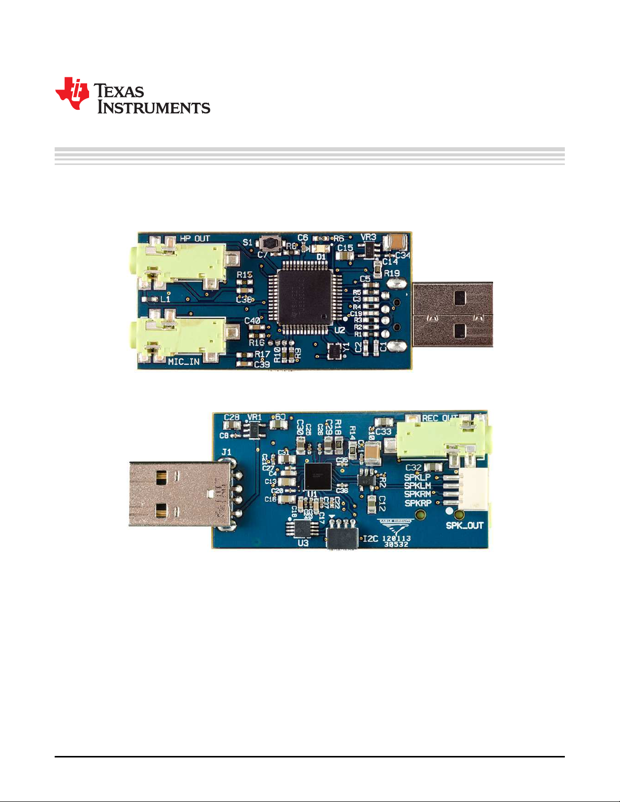
This user's guide describes the features, software and typical configurations of TLV320AIC3262 stick
evaluation module (EVM). This small form factor evaluation module is a programmable USB audio device
that features the TLV320AIC3262 audio codec with miniDSP.
Figure 1. TLV320AIC3262 Stick EVM Front View
Figure 2. TLV320AIC3262 Stick EVM Back View
4
Introduction SLAU448–June 2012
Copyright © 2012, Texas Instruments Incorporated
Submit Documentation Feedback
Page 5
Chapter 1
SLAU448–June 2012
TLV320AIC3262 EVM Software
The TLV320AIC3262 EVM graphical user interface (GUI) can be downloaded from TLV320AIC3262 online
product folder: http://www.ti.com/. A detailed description of how to use the GUI is introduced in
SLAU386A.
SLAU448–June 2012 TLV320AIC3262 EVM Software
Submit Documentation Feedback
Copyright © 2012, Texas Instruments Incorporated
5
Page 6

Chapter 2
SLAU448–June 2012
Use TLV320AIC3262 Stick EVM for
Typical Playback and Recording Configuration
1. Connect the TLV320AIC3262 stick EVM to your PC universal serial bus (USB) port. The light-emitting
diode (LED) light D1 will turn on. If the LED light is not on, follow Appendix A to flash electrically
erasable programmable read-only memory (EEPROM) image.
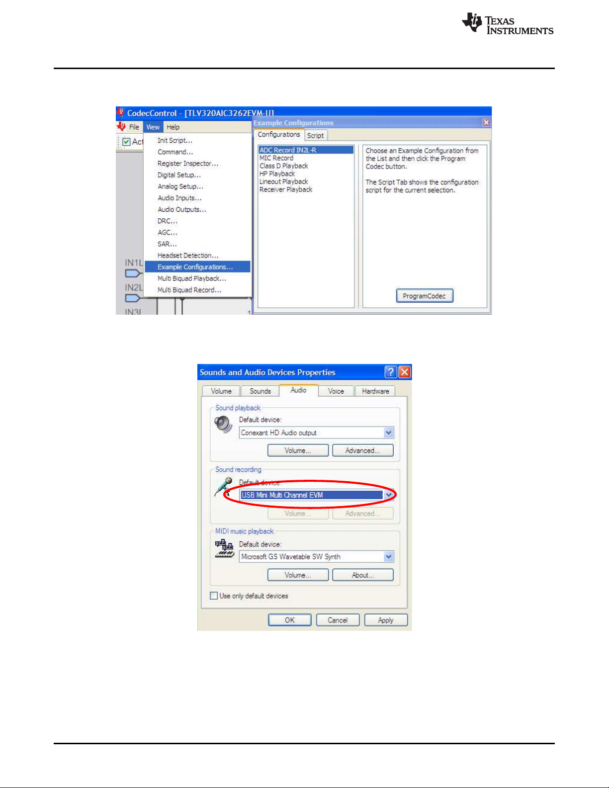
2. Open the Codec Control GUI. This software can be downloaded from the TLV320AIC3262 product
folder. The bottom part of the GUI main panel shows the connection status of the EVM as well as the
current sampling rate.
Go to Appendix A if the sampling rate of the EVM should be changed.
3. Headphone playback configuration (default script works for 48 kHz or 44.1 kHz Fs)
• Connect the headset to TLV320AIC3262 stick EVM connector HP_OUT
• Go to View → Example Configurations… → HP Playback, and then click the Program Codec
button.
• Play the music file through any windows media player. Make sure the sound playback default
device is set as USB Mini Multi Channel EVM.
6
Use TLV320AIC3262 Stick EVM for Typical Playback and Recording SLAU448–June 2012
Configuration
Copyright © 2012, Texas Instruments Incorporated
Submit Documentation Feedback
Page 7

www.ti.com
4. SPK playback configuration (default script works for 48 kHz or 44.1 kHz Fs)
• Use the speaker cable provided to connect stereo speakers to the SPK_OUT connector of the
TLV320AIC3262 stick EVM.
• Go to View → Example Configurations…→ Class D Playback, and then click the Program Codec
button.
• Play the music file through any windows media player. Make sure the sound playback default
device is set as USB Mini Multi Channel EVM (same as HP playback).
5. Microphone recording configuration (default script works for 48 kHz or 44.1 kHz Fs)
• Connect the stereo single-ended microphone to the MIC_IN connector of the TLV320AIC3262 stick
EVM.
SLAU448–June 2012 Use TLV320AIC3262 Stick EVM for Typical Playback and Recording
Submit Documentation Feedback
Copyright © 2012, Texas Instruments Incorporated
Configuration
7
Page 8
www.ti.com
• Go to View → Example Configurations… → ADC Record IN2L-R, and then click the Program
Codec button.
• Turn on MICBIAS by writing b0_p1_r51 = 0x07 (w 30 33 07) in the command line interface.
• Record through any windows recording software (for example, Goldwave). Make sure the sound
recording default device is set as USB Mini Multi Channel EVM.
6. Receiver playback configuration (default script works for 48 kHz or 44.1 kHz Fs)
• Connect the mono receiver to the REC_OUT connector of the TLV320AIC3262 stick EVM.
• Go to View → Example Configurations… → Receiver Playback, and then click the Program Codec
button.
8
Use TLV320AIC3262 Stick EVM for Typical Playback and Recording SLAU448–June 2012
Configuration
Copyright © 2012, Texas Instruments Incorporated
Submit Documentation Feedback
Page 9

www.ti.com
• Play the music file through any windows media player. Make sure the sound playback default
device is set as USB Mini Multi Channel EVM (same as HP playback).
SLAU448–June 2012 Use TLV320AIC3262 Stick EVM for Typical Playback and Recording
Submit Documentation Feedback
Copyright © 2012, Texas Instruments Incorporated
Configuration
9
Page 10

GND
GND
GND
GND
GND GND
GND
3.3 V
3.3 V
3.3 V
3.3 V
GND
GND
GND
GND
GND
5 V-USB
6 MHz/3.3 V
SMT-8002
4
3
2
1
Y1
GNDOEOUT
V
CC
21
S1
3.3 V
3.3 V
TYPEA_PCB-RA
J1
1
2
3
4
5
6
7
8
NC
NC
CASE
CASE
Data+
GND
5 V
Data-
5 V-USB
GND
GND
I C
2
1
2
3
4
27.4
0603
R4
1 2
47 pfd/50 V
0603
2
1
C3
GND
47 pfd/50 V
0603
C19
1
2
27.4
0603
21
R3
1.50K
0603
R2
1 2
1 µfd/16 V
0603
2
1
C5
649
0603
21
R6
Yellow
0805
D1
3.3 V
3.3 V
100 pfd/50 V
0603
C2
1
2
3.09K
0603
2 1
R1
1000 pfd/50 V
0603
2 1
C1
3.3 V
0.1 µfd/16 V
0402
C6
1
2
0.1 µfd/16 V
0402
2
1
C7
10K
0603
R8
1
2
5 V-USB
GND
GND
GNDGND
1.8 V/400 mA
SOT230DBV5
5
43
2
1
TPS73618DBV
VR1
0.1 µfd/16 V
0402
C8
1
2
10 µfd/10 V
0805
C28
2
1
47 µfd/6.3 V
0805
2
1
C9
1.8V
5 V-USB
GND
GND
GNDGND
1.8 V/400 mA
SOT230DBV5
VR2
TPS73618DBV
1
2
3 4
5
0.1 µfd/16 V
0402
2
1
C11
47 µfd/6.3 V
0805
C12
1
2
1.8VD
GND
GND
GND
3.3 V/400 mA
SOT230DBV5
5
43
2
1
TPS73633DBV
VR3
0.1 µfd/16 V
0402
C14
1
2
47 µfd/6.3 V
0805
2
1
C15
3.3 V
MSOP8-DGK
U3
1
2
3
4 5
6
7
8
GND
3.3 V
2.20K
0603
21
R9
2.20K
0603
R10
1 2
3.3 V
10K
0603
R5
1 2
3.3 V
5 V-USB
2 1/4 W
0805
R19
1 2
47 µfd/10 V
1210
C34
1
2
GND
2 1/4 W
0805
R14
21
47 µfd/10 V
1210
C10
2
1
TQFP52-PAH
1
2
3
4
5
6
7
8
9
10
11
12
13
14
151617
18
19
202122
23
24
25
26
27
28
29
30
31
32
33
34
35
36
37
38
39
40
41
42
43
44
45
46
47
48
495051
52
TUSB3200ACPAH
U2
TLV320AIC3262YZF EVALUATION BOARD (USB STICK)
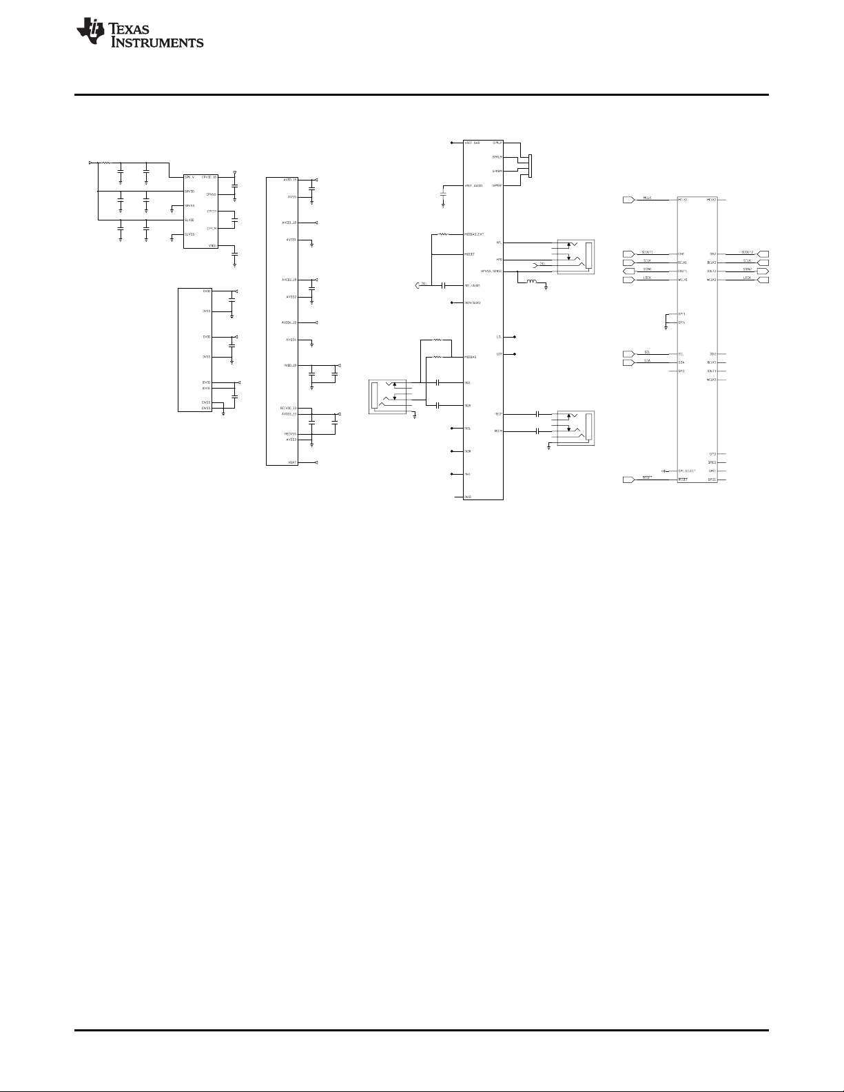
Chapter 3
SLAU448–June 2012
TLV320AIC3262 Stick EVM Schematics
Figure 3-1. EVM Schematic 1
Submit Documentation Feedback
10
TLV320AIC3262 Stick EVM Schematics SLAU448–June 2012
Copyright © 2012, Texas Instruments Incorporated
Page 11
GND
GND
GND
GND
GND
GND
GND
GND
GND
GND
GND
2.2 µfd/25 V
0805
C13
1
2
2.2 µfd/25 V
0805
C16
1
2
5 V-USB
WCSP81-YZF
TLV320AIC3262YZF
U1
F9
C7
E5
A2
A1
A3
A8
B4
E6
C5
E4
C2
E3
F3
WCSP81-YZF
U1
TLV320AIC3262YZF
J4
H9
F4
J3
E7
J9
F8
H3
WCSP81-YZF
U1
TLV320AIC3262YZF
A7
B6
B7
A6
A5
B9
B8
D8
D9
E8
4.7 µfd/6.3 V
0603
2
1
C4
4.7 µfd/6.3 V
0603
C17
1
2
4.7 µfd/6.3 V
0603
C18
2
1
GND
10 µfd/10 V
0805
2
1
C29
1.8 V
1.8 VD
1.8 VD
1.8 VD
1.8 VD
1.8 VD
3.3V
1.8 VD
1.8 VD
3.3V
GND
0.1 µfd/16 V
0402
1
2
C26
5 V-USB
21/4 W
0805
1 2
R18
GND
10 µfd/10 V
0805
1
2
C30
GND
0.1 µfd/16 V
0402
2
1
C25
GND
10 µfd/10 V
0805
2
1
C31
GND
0.1 µfd/16 V
0402
1
2
C27
GND
GND
1µfd/6.3 V
0402
1
2
C36
1 µfd/6.3 V
0402
2
1
C35
0.1 µfd/16 V
0402
1
2
C21
0.1 µfd/16 V
0402
1
2
C20
0.1 µfd/16 V
0402
1
2
C22
0.1 µfd/16 V
0402
1
2
C23
0.1 µfd/16 V
0402
C24
1
2
GND
GND
3.5 mm
HPOUT
5
6
3
1
4
2
Shield
RIGHT
LEFT
3.5 mm
RECOUT
5
6
3
1
4
2
Shield
RIGHT
LEFT
GND
1.5 mm
SPK_OUT
1
2
3
4
WCSP81-YZF
TLV320AIC3262YZF
U1
D5
C1
D2
D6
A4
B5
E9
C9
A9
C8
B2
B3
C6
D7
E1
E2
F2
F1
C3
B1
D4
D3
D1
C4
GND
3.5 mm
MIC_IN
5
6
3
1
4
2
Shield
RIGHT
LEFT
1µ fd/10 V
0402
1
2
C37
2.20K
0603
1 2
R15
2.20K
0603
21
R17
2.20K
0603
1 2
R16
47 µfd/6.3 V
0805
1 2
C33
47 µfd/6.3 V
0805
21
C32
0.47 µd/25 V
0603
1 2
C39
0.47 µd/25 V
0603
21
C40
0.47 µd/25 V
0603
21
C38
220 /2 AΩ
0603
L1
1
2
GND
WCSP81-YZF
U1
TLV320AIC3262YZF
F7
F5
G6
H7
G5
J7
F6
H8
J8
H6
G9
G3
G7
J5
H4
H5
G8
H1
J2
J1
G2
G4
J6
G1
H2
GND
TLV320AIC3262YZF EVALUATION BOARD (USB STICK)
www.ti.com
Figure 3-2. EVM Schematic 2
SLAU448–June 2012 TLV320AIC3262 Stick EVM Schematics
Submit Documentation Feedback
Copyright © 2012, Texas Instruments Incorporated
11
Page 12

I C connector on TLV320AIC3262 stick EVM
2
1. SCL
2. SDA
3. GND
4. IOV
DD
Appendix A
SLAU448–June 2012
TLV320AIC3262 Stick EVM EEPROM
Image Programming Guide
1. Install the TotalPhaseUSB-v2.10 driver using TotalPhaseUSB-v2.10.exe. This driver installation file is
located at: \\vette02\dg_audio\USERS\Austin\software.
2. Open the Aardvark™ GUI by double-clicking on Aardvark GUI.exe. Aardvark GUI is located at:
\\vette02\dg_audio\USERS\Austin\software\aardvark-gui-windows-v3.53.
3. Setup the hardware.
• Build the I2C®(SDA, SCL, IOVDD, GND) connection between the Aardvark GUI and the
TLV320AIC3262 stick EVM.
12
SCL SDA NC + 5 V GND
Aardvark GUI 1 3 4 2
TLV320AIC3262 I2C connector 1 2 4 3
• Connect the Aardvark GUI to a PC through USB cable. Now the Aardvark GUI will be recognized
as the Total Phase Aardvark I2C/SPI Host Adaptor under the windows device manager.
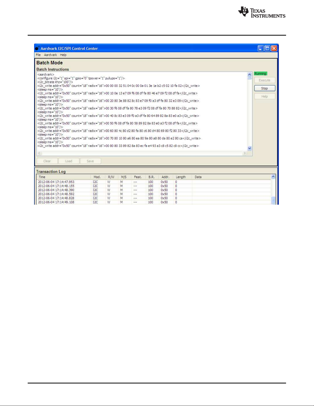
4. Program the TUSB3200 firmware (\\vette02\dg_audio\USERS\Austin\software\TUSB3200 image)
• Open the Aardvark GUI and click Configure Aardvark Adaptor
• Highlight the Aardvark port and select Batch Mode, then click okay.
TLV320AIC3262 Stick EVM EEPROM Image Programming Guide SLAU448–June 2012
Copyright © 2012, Texas Instruments Incorporated
Submit Documentation Feedback
Page 13

www.ti.com
Appendix A
• Click Load and select the TUSB3200firmware.xml file, then click Execute. The
TUSB3200firmware.xml file is located at \\vette02\dg_audio\USERS\Austin\software
• If the I2C communication is okay, the status line turns green and shows Running.
SLAU448–June 2012 TLV320AIC3262 Stick EVM EEPROM Image Programming Guide
Submit Documentation Feedback
Copyright © 2012, Texas Instruments Incorporated
13
Page 14
Appendix A
www.ti.com
The status line turns red when the download completes.
• Disconnect the TLV320AIC3262 stick EVM from the Aardvark GUI and connect the
TLV320AIC3262 stick EVM directly to a PC.
• Open the TLV320AIC3254 Control Software. The sample rate of the stick EVM should be 48 kHz.
14
TLV320AIC3262 Stick EVM EEPROM Image Programming Guide SLAU448–June 2012
Copyright © 2012, Texas Instruments Incorporated
Submit Documentation Feedback
Page 15

www.ti.com
Appendix A
5. To change the TLV320AIC3262 Stick EVM EEPROM image to other sample rate:
• Click on EEPROM Writer
• Under step 1, choose the desired TUSB3200 firmware with the corresponding sample rate. The
TUSB3200 firmware is located at \\vette02\dg_audio\USERS\Austin\software\TUSB3200_image
• Click Program EEPROM to download the TUSB3200 firmware into an external EEPROM
• Wait until the Activity LED light stops blinking
• Disconnect and connect the TLV320AIC3262 stick EVM to a PC again, and the sample rate should
be updated accordingly.
SLAU448–June 2012 TLV320AIC3262 Stick EVM EEPROM Image Programming Guide
Submit Documentation Feedback
Copyright © 2012, Texas Instruments Incorporated
15
Page 16

IMPORTANT NOTICE
Texas Instruments Incorporated and its subsidiaries (TI) reserve the right to make corrections, modifications, enhancements, improvements,
and other changes to its products and services at any time and to discontinue any product or service without notice. Customers should
obtain the latest relevant information before placing orders and should verify that such information is current and complete. All products are
sold subject to TI’s terms and conditions of sale supplied at the time of order acknowledgment.
TI warrants performance of its hardware products to the specifications applicable at the time of sale in accordance with TI’s standard
warranty. Testing and other quality control techniques are used to the extent TI deems necessary to support this warranty. Except where
mandated by government requirements, testing of all parameters of each product is not necessarily performed.
TI assumes no liability for applications assistance or customer product design. Customers are responsible for their products and
applications using TI components. To minimize the risks associated with customer products and applications, customers should provide
adequate design and operating safeguards.
TI does not warrant or represent that any license, either express or implied, is granted under any TI patent right, copyright, mask work right,
or other TI intellectual property right relating to any combination, machine, or process in which TI products or services are used. Information
published by TI regarding third-party products or services does not constitute a license from TI to use such products or services or a
warranty or endorsement thereof. Use of such information may require a license from a third party under the patents or other intellectual
property of the third party, or a license from TI under the patents or other intellectual property of TI.
Reproduction of TI information in TI data books or data sheets is permissible only if reproduction is without alteration and is accompanied
by all associated warranties, conditions, limitations, and notices. Reproduction of this information with alteration is an unfair and deceptive
business practice. TI is not responsible or liable for such altered documentation. Information of third parties may be subject to additional
restrictions.
Resale of TI products or services with statements different from or beyond the parameters stated by TI for that product or service voids all
express and any implied warranties for the associated TI product or service and is an unfair and deceptive business practice. TI is not
responsible or liable for any such statements.
TI products are not authorized for use in safety-critical applications (such as life support) where a failure of the TI product would reasonably
be expected to cause severe personal injury or death, unless officers of the parties have executed an agreement specifically governing
such use. Buyers represent that they have all necessary expertise in the safety and regulatory ramifications of their applications, and
acknowledge and agree that they are solely responsible for all legal, regulatory and safety-related requirements concerning their products
and any use of TI products in such safety-critical applications, notwithstanding any applications-related information or support that may be
provided by TI. Further, Buyers must fully indemnify TI and its representatives against any damages arising out of the use of TI products in
such safety-critical applications.
TI products are neither designed nor intended for use in military/aerospace applications or environments unless the TI products are
specifically designated by TI as military-grade or "enhanced plastic." Only products designated by TI as military-grade meet military
specifications. Buyers acknowledge and agree that any such use of TI products which TI has not designated as military-grade is solely at
the Buyer's risk, and that they are solely responsible for compliance with all legal and regulatory requirements in connection with such use.
TI products are neither designed nor intended for use in automotive applications or environments unless the specific TI products are
designated by TI as compliant with ISO/TS 16949 requirements. Buyers acknowledge and agree that, if they use any non-designated
products in automotive applications, TI will not be responsible for any failure to meet such requirements.
Following are URLs where you can obtain information on other Texas Instruments products and application solutions:
Products Applications
Audio www.ti.com/audio Automotive and Transportation www.ti.com/automotive
Amplifiers amplifier.ti.com Communications and Telecom www.ti.com/communications
Data Converters dataconverter.ti.com Computers and Peripherals www.ti.com/computers
DLP® Products www.dlp.com Consumer Electronics www.ti.com/consumer-apps
DSP dsp.ti.com Energy and Lighting www.ti.com/energy
Clocks and Timers www.ti.com/clocks Industrial www.ti.com/industrial
Interface interface.ti.com Medical www.ti.com/medical
Logic logic.ti.com Security www.ti.com/security
Power Mgmt power.ti.com Space, Avionics and Defense www.ti.com/space-avionics-defense
Microcontrollers microcontroller.ti.com Video and Imaging www.ti.com/video
RFID www.ti-rfid.com
OMAP Mobile Processors www.ti.com/omap
Wireless Connectivity www.ti.com/wirelessconnectivity
TI E2E Community Home Page e2e.ti.com
Mailing Address: Texas Instruments, Post Office Box 655303, Dallas, Texas 75265
Copyright © 2012, Texas Instruments Incorporated
 Loading...