

Page 1

Basic Kit Construction Guide
TI Robotics System Learning Kit (TI-RSLK):
Page 2

Table of Contents:
3 Lab Tools Needed
4 Section 1: Soldering
15 Section 2: Assembly
22 Section 3: Wiring
2 Texas Instruments Robotics Systems Learning Kit: The Maze Edition
SWRP249
Page 3
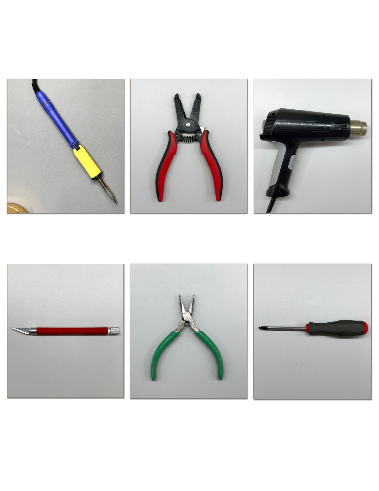
Soldering Iron
Wire Stripper and Cutter
Heat Gun (optional)
Precision Knife
Pliers
Screwdriver
Lab Tools
3 Texas Instruments Robotics Systems Learning Kit: The Maze Edition
SWRP249
Page 4
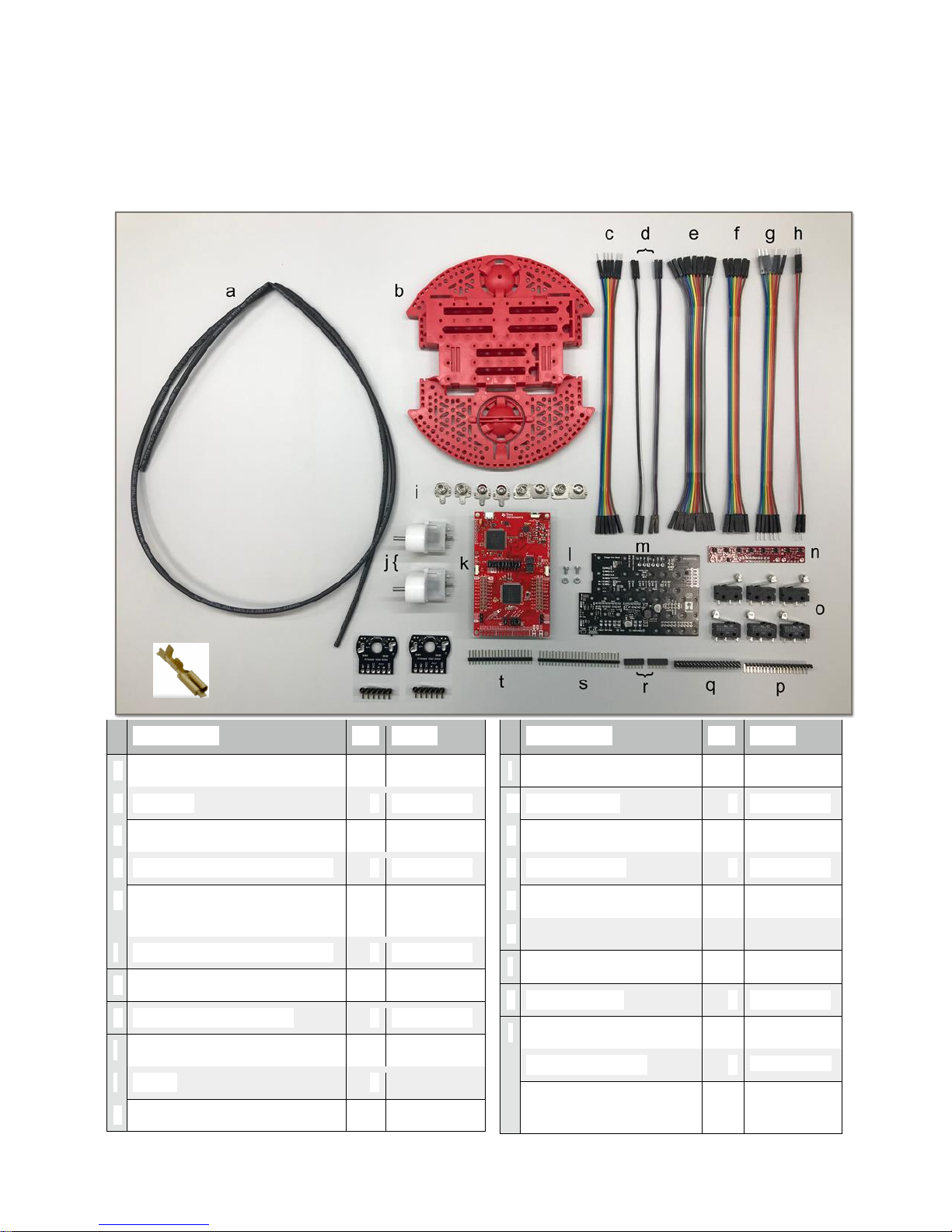
Description
Qty
Part #
a
Heat Shrink Tube
1
01M8939
b
Chassis
1
55AC1156
c
6 Female to Male Wires
1
44AC9484
d
2 Female to Female Wires
4
44AC9484
e
11 Female to Female
Wires
1
44AC9484
f
6 Female to Female Wires
1
44AC9484
g
6 Male to Male Wires
1
44AC9484
h
2 Male to Male Wires
1
44AC9484
i
Battery Terminals
1
55AC1157
j
Motor
2
55AC1157
k
TI LaunchPad™ Kit
1
41Y9541
Description
Qty
Part #
l
Motor Board Screws
1
55AC1157
m
Motor Board
1
55AC1157
n
Line Follower Sensor
1
55AC1158
o
Bump Switch
6
55AC1159
p
90º Bent Headers
1
08N6741
q
2x20 Header
1
93K5757
r
1x6 Header
2
55AC1157
s
1x25 Header
1
55AC1158
t
1x20 Header
1
08N6754
u
Motor Encoders
2
*not included
v
Bump switch wire
spade connector
12
*not included
v
Section 1: Soldering
Step 1: Gather Your Supplies
u
4 Texas Instruments Robotics Systems Learning Kit: The Maze Edition
SWRP249
Page 5
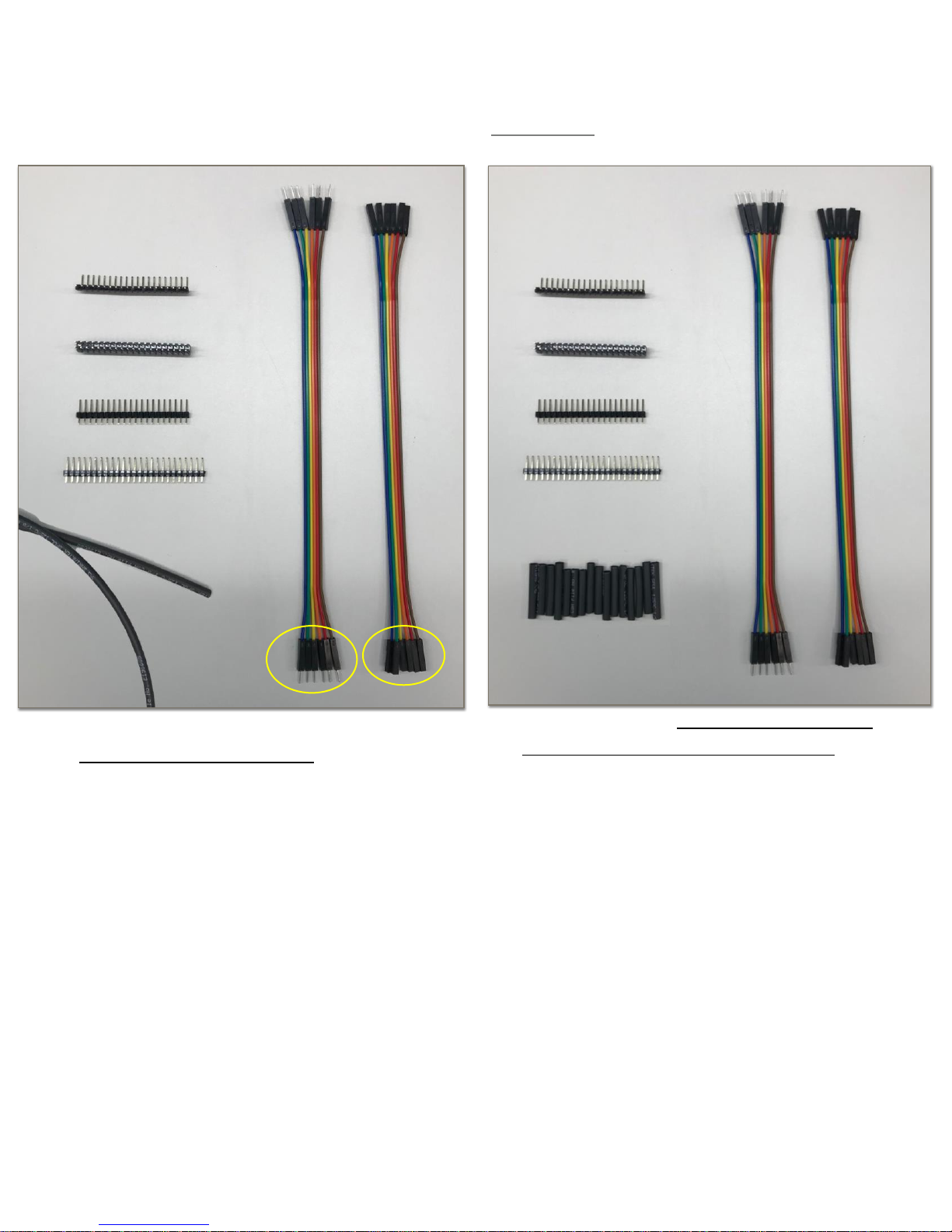
Gather the following:
-
Heat Shrink Tubing (a)
-
6 Female to Female Wires (f)
-
6 Male to Male Wires (g)
-
90º Bent Headers (v)
-
2x20 Header (u)
-
1x20 Header (r)
-
1x25 Header (s)
(optional step) Cut the heat shrink
tubing (a) into 12 1in (~2.5cm)
Step 2: Prepare Headers, Tubing, and Wires
5 Texas Instruments Robotics Systems Learning Kit: The Maze Edition
SWRP249
Page 6
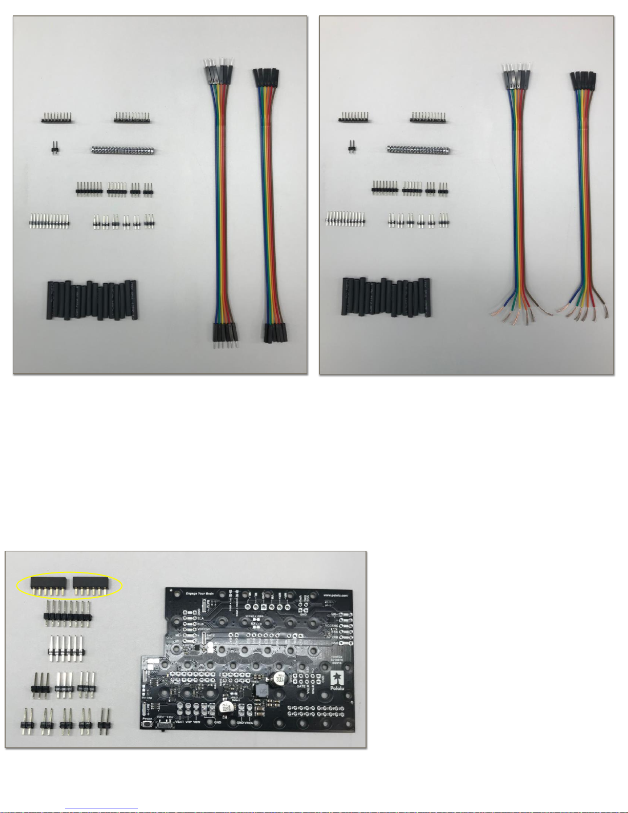
Cut the following:
-
90º bent headers (v) into a 1x11
-
2x20 header (u) into a 2x19
-
1x20 header (r) into a 1x8, 1x6,
and two 1x3
-
1x25 header (s) into a 1x3 and
five 1x2
Cut and strip one end off of the 6 female
to female wires (f) using the wire stripper.
Cut and strip one end off of the 6 male to
male wires (g) using the wire stripper.
Make sure the wire stripping is relatively
even, if you mess up you can trim to fit
Gather the following:
-
Motor Board (m)
-
1x8 Header (Prepared earlier)
-
1x6 Header (Prepared earlier)
-
3 1x3 Headers (Prepared earlier)
-
5 1x2 Headers (Prepared earlier)
-
2 1x6 Female Socket Headers
for encoders (t)
Step 3: Prepare the Motor Board
6 Texas Instruments Robotics Systems Learning Kit: The Maze Edition
SWRP249
Page 7
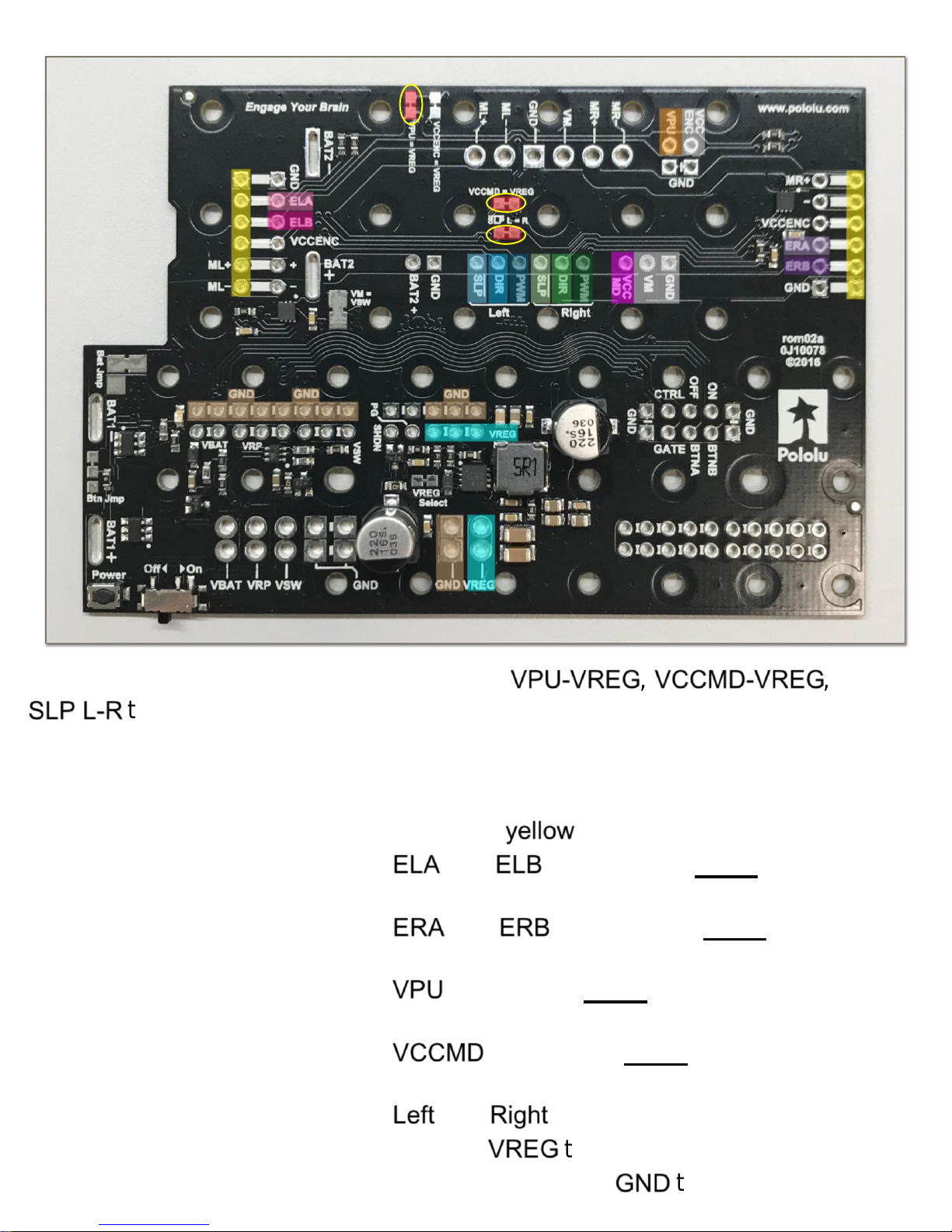
Cut Traces: Use a precision knife to cut the , , and
VPU-VREG VCCMD-VREG
traces. Make a deep solid cut through the small line connection between
SLP L-R
the square pads. No need to scratch out the pads or be excessive with the cuts.
Solder the following:
-
two 1x6 female socket headers (t) to the connections.
yellow
-
a 1x2 header cut earlier to the and
ELA
connections. Note: You will need
ELB
to bend these to a 45º angle after soldering.
-
a 1x2 header cut earlier to the and
ERA
connections. Note: You will need
ERB
to bend these to a 45º angle after soldering.
-
a 1x2 header cut earlier to the connection. Note: The white connection
VPU
will never be used but helps with soldering.
-
a 1x3 header cut earlier to the connection. Note: The white
VCCMD
connection will never be used but helps with soldering.
-
a 1x6 header cut earlier to the and
Left
motor driver connections.
Right
-
a 1x3 and 1x2 header cut earlier to the terminals.
VREG
-
solder 1x8, 1x3, and 1x2 headers cut earlier to the terminals.
GND
7 Texas Instruments Robotics Systems Learning Kit: The Maze Edition
SWRP249
Page 8
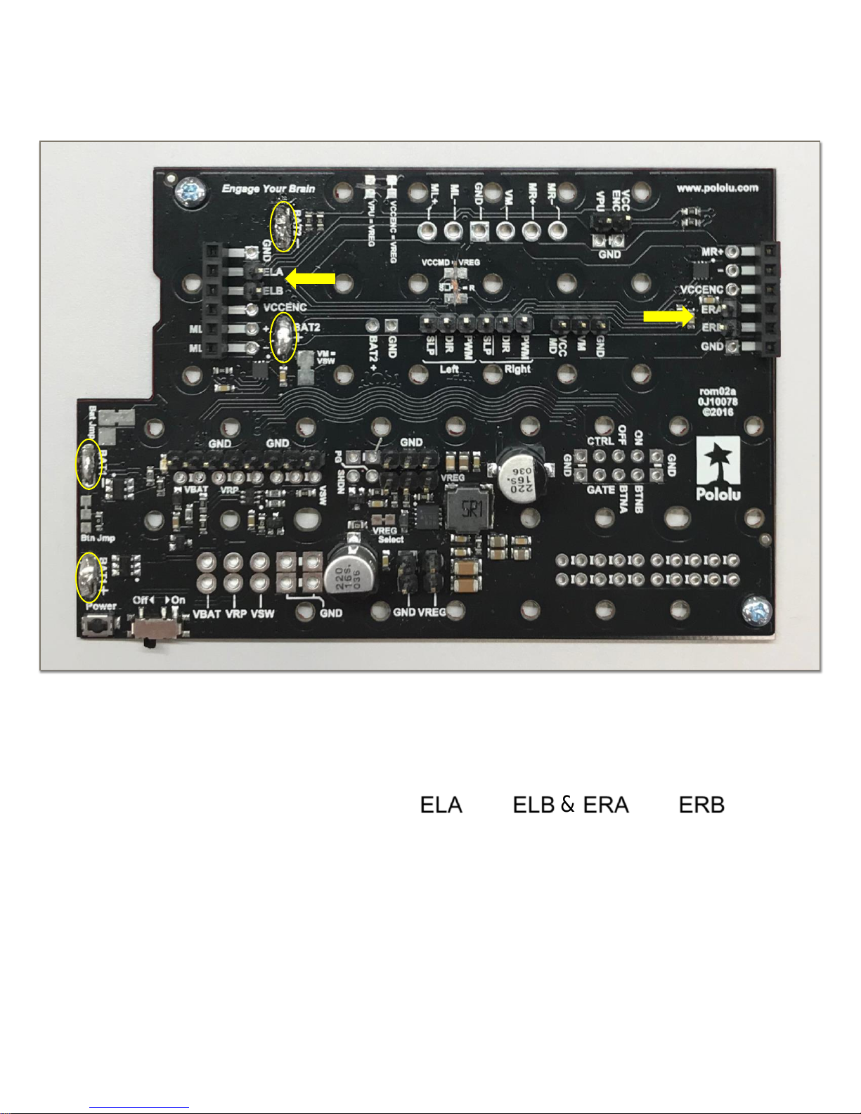
Finished Motor Board:
You will solder the four battery connections later on as part of the attachment to
the chassis. You will secure the board with two support screws later.
You should use pliers to bend out the and
ELA
&
ELB
and
ERA
ERB
connections so they can be connected by wires to the LaunchPad later. As long
as the headers are properly soldered they should be strong enough to bend out
slightly without issue or causing damage.
8 Texas Instruments Robotics Systems Learning Kit: The Maze Edition
SWRP249
Page 9

Gather:
-
Soldered Motor Board (m)
-
Battery Terminals (i)
-
Chassis (b)
-
Screws for Motor Board (l)
Flip chassis (b) over.
Remove battery cover.
Insert the linking
battery terminals (i) into
the slots on the left.
Put battery cover back on and
flip chassis (b) over.
Insert battery tabs into
the slots on the left.
Note: the order from
top to bottom is spring,
flat tab, spring, flat tab.
Step 4: Connect Battery Terminals and Chassis
9 Texas Instruments Robotics Systems Learning Kit: The Maze Edition
SWRP249
Page 10

Attach to Chassis:
Solder the motor board (m)
onto the battery terminals and
secure the motor board (m)
with two screws (l).
(Optional) Using a voltage
meter, verify that the earlier
solder connections were made
and traces were cut on the
motor board (m).
Gather your
LaunchPad (k) and
the 2x19 header you
cut earlier.
Solder the 2x19
header on the J5
pinout at the bottom
of the LaunchPad (k)
with long pins facing
upwards.
Step 5: Solder LaunchPad Connections
10 Texas Instruments Robotics Systems Learning Kit: The Maze Edition
SWRP249
Page 11

Gather:
-
Motors (j)
-
2 Motor Encoders (u)
Solder the included encoder headers
(u) to the encoders (u). Note: The bent
portion of the headers should be
towards the motor as pictured above.
Attach the magnets onto the motors (i).
Step 6: Ready the Motors
Solder the prepared encoders (j) onto
the motors (i). Note: The encoder
adapter should be flush with the motor
as pictured above.
11 Texas Instruments Robotics Systems Learning Kit: The Maze Edition
SWRP249
Page 12

Gather the line sensor (n) and the
1x11 90º bent headers cut earlier.
Solder the 1x11 bent headers onto the
line sensor (n). Connect the highlighted
3.3V bypass by either creating a solder
bridge or soldering a short wire from your
extra wire clippings.
Gather the following:
-
6 Bump Switches (o)
-
12 Heat Shrink Tube pieces cut
earlier (a)
-
6 Female wire with one end cut
and stripped from earlier (f)
-
6 Male wire with one end cut and
stripped from earlier (g)
-
12 Bump Switch wire spade
connectors (v) *not included in kit
Note: You can solder the wires
directly to the bump switches in the
next step but using the spade
connector is much better. If you
have a crimper tool this will be
easier task but you can manually
crimp with pliers or a wire cutter
Step 7: Solder the Line Sensor Connections
Step 8: Prepare the Bump Switches
12 Texas Instruments Robotics Systems Learning Kit: The Maze Edition
SWRP249
Page 13

Start with the 6
female wires (f).
Crimp a wire connector
(v) on each wire.
Attach one female wire on
the “1” or “C” connection
on each bump switch (0).
Ready the 6 male wires (g).
Note: you can separate
each wire but for a cleaner
look try to keep them
together.
Crimp a wire connector (v)
on each wire.
Attach one male wire on
the “3” or “NO”
connection on each
bump switch (0). Color
coding each switch will
help you later when
wiring.
13 Texas Instruments Robotics Systems Learning Kit: The Maze Edition
SWRP249
Page 14

Section 2: Assembly
Step 1: Gather Supplies
Description
Qty
Part #
a
#2-56 Screw 1/2”
12
55AC7011
b
#2-56 Nut
12
18M5986
c
#2-56 Screw 1/4”
4
56AC1176
d
#2-56 Metal Standoff
1/2“
2
27T8693
e
#4-40 Screw 1/2”
4
55AC7009
f
#4-40 Plastic Standoffs
4
16F1043
g
#4-40 Nut
4
43AC8400
Description
Qty
Part #
h
Prepared Motor w/
Encoders
2
55AC1157
i
Motor Clip
2
55AC1156
j
Ball Caster
1
55AC1156
k
Prepared Line Sensor
1
55AC1159
l
Rubber Tire
2
55AC1156
m
Wheel
2
55AC1156
n
Prepared Chassis
1
55AC1156
o
Prepared Bump Switch
1
55AC1159
14 Texas Instruments Robotics Systems Learning Kit: The Maze Edition
SWRP249
Page 15

Gather:
-
Prepared Chassis and
Motor Board (n)
-
Motor Clips (i)
-
Prepared Motors (h)
Insert the motor clips
(i) into the motor
board (n) as shown
above.
Ensure the motor clips
(i) are fully inserted.
Fully slide the motors
(h) into the motor clips
(i) with gentle pressure
as shown above. Be
careful not to overstress the clips.
Step 2: Attach Motors
The pins from the
encoders should plug
into the motor board.
Ensure they are not
in contact with the
bent pins.
15 Texas Instruments Robotics Systems Learning Kit: The Maze Edition
SWRP249
Page 16

Gather your Chassis
(n) and the Ball Caster
parts (j).
Place the three
small wheels in
the groves on the
short side as
shown above.
Place the white
ball in the grove
as shown above.
Secure the
assembly with the
final piece.
Gather:
-
Prepared Chassis
-
Wheels (m)
-
Rubber Tires (l)
Attach rubber
tires (l) to the
wheels (m).
Attach the prepared wheel to the
motor. Please be sure to align the flat
portions of the wheel and motor.
Step 3: Attach Ball Caster
Step 4: Attach Wheels
16 Texas Instruments Robotics Systems Learning Kit: The Maze Edition
SWRP249
Page 17

Gather:
-
Prepared Chassis
-
11 Female to Female Wires
(e from pg. 4)
-
Screws #2-56 1/4” (e)
-
Standoffs #2-56 (f)
-
Line Sensor (n)
Attach the standoffs (f) to the
bottom of the chassis with
two screws (e) at the
highlighted locations.
Run the wires (e from pg.
4) through the middle
hole of the chassis.
Attach the line sensor (n)
using two screws (e) to
the standoffs (f) you just
attached.
Step 5: Attach Line Sensor
17 Texas Instruments Robotics Systems Learning Kit: The Maze Edition
SWRP249
Page 18

Gather:
-
Prepared Chassis
-
Bump Switches (u)
-
Screws #2-56 1/2” (a)
-
Nuts #2-56 (b)
Note: you may find it easier to
fish the screw from the bottom
and secure with the nut on the
top of the bump switch. Both
orientations when secure can
work.
Attach the bump switches (u)
to the Prepared Chassis via
the holes above using the
nuts (b) and screws (a).
Bottom View
Step 6: Attach Bump Switches
18 Texas Instruments Robotics Systems Learning Kit: The Maze Edition
SWRP249
Page 19

Gather:
-
Prepared Chassis
-
Plastic Standoffs (h)
-
Screws #4-40 1/2” (g)
-
Nuts #4-40 (j)
Attach the standoffs (h) to the top
of the chassis with screws (g) from
the bottom via the highlighted
areas above. Do not over tighten
or screw them all the way in.
You will use four nuts (j) to
attach the LaunchPad
after the next section.
Note: the chassis holes
may be slightly too small,
but the screws will fit.
Press the screws firmly
through.
Step 7: Attach LaunchPad Standoffs
19 Texas Instruments Robotics Systems Learning Kit: The Maze Edition
SWRP249
Page 20

Connect the “1” or “C” output (female wire) from each bumper to GND
on the motor board. Connect the “3” or “NO” output (male wire) from
each bumper to the LaunchPad underside female inputs below.
Bump 1
Bump 2
Bump 3
Bump 4
Bump 5
Bump 6
LaunchPad
P4.0
P4.2
P4.3
P4.5
P4.6
P4.7
Section 3: Wiring
Step 1: Bump Switches
20 Texas Instruments Robotics Systems Learning Kit: The Maze Edition
SWRP249
Page 21

Using the 6 female to male wires (c from pg. 4), connect the male motor driver
connections to the LaunchPad underside female outputs below.
Motor Board
Left SLP
Left DIR
Left PWM
Right SLP
Right DIR
Right PWM
LaunchPad
P3.7
P1.7
P2.7
P3.6
P1.6
P2.6
Step 2: Motor Board Logic
21 Texas Instruments Robotics Systems Learning Kit: The Maze Edition
SWRP249
Page 22

Using the 2 female to female wires (d from pg. 4), connect the VPU and VCCMD
connections to the LaunchPad’s 3.3V outputs (3V3).
Motor Board
VPU
VCCMD
LaunchPad
3V3
3V3
Step 3: Motor Board Power
22 Texas Instruments Robotics Systems Learning Kit: The Maze Edition
SWRP249
Page 23

Using the 2 female to female wires (d from pg. 4), connect the VREG and GND
connections to the LaunchPad 5V and GND connections respectively.
Note: You must disconnect these wires every time you connect your LaunchPad to
your computer via USB. You do not want to have the robot batteries connected up
while the LaunchPad is being programmed or powered by the PC!
Motor Board
VREG
GND
LaunchPad
5V
GND
Step 4: LaunchPad Power
23 Texas Instruments Robotics Systems Learning Kit: The Maze Edition
SWRP249
Page 24

Line Sensor
8 7 6 5 4
3
2
1
LED ON
VCC
GND
LaunchPad
P7.7
P7.6
P7.5
P7.4
P7.3
P7.2
P7.1
P7.0
P5.3
3V3
GND
Using the 11 female to female wires (e from pg. 4) you fed
through the chassis earlier (Step 5 on pg. 17) make the below
connections between the line sensor and LaunchPad top side.
Step 5: Line Follow Sensor
24 Texas Instruments Robotics Systems Learning Kit: The Maze Edition
SWRP249
Page 25

Next, secure the LaunchPad to the LaunchPad standoffs using the nuts you set
aside earlier. If wires are on the bottom you may need to gently and carefully
maneuver the LaunchPad to align with the standoffs.
Note: You have the ability to add BoosterPacks to the top of the RSLK for
adding capabilities and more learning experiences.
Step 6: Attach LaunchPad
Congratulations; your TI-RSLK is built!
25 Texas Instruments Robotics Systems Learning Kit: The Maze Edition
SWRP249
 Loading...