

Page 1

TIDA-00293 DLP®3D Printer User's Guide
User's Guide
Literature Number: DLPU025
September 2014
Page 2

Contents
Preface ........................................................................................................................................ 6
1 Introduction to the DLP
1.1 ................................................................................................................................. 7
1.2 Stereolithography ............................................................................................................ 7
1.3 How the DLP 3D Printer Reference Design Works ..................................................................... 7
1.3.1 DLP Structured Light SDK......................................................................................... 7
1.3.2 Photo-resins ........................................................................................................ 7
1.3.3 DLP LightCrafter™ 4500 Evaluation Module.................................................................... 7
1.3.4 Velmex XSlide™ Translation Stage.............................................................................. 7
1.3.5 Mechanical Structure............................................................................................... 8
1.3.6 DLP 3D Printer Microcontroller.................................................................................... 8
1.3.7 Front Panel User Interface ........................................................................................ 8
1.3.8 DLP 3D Printer Graphical User Interface........................................................................ 8
1.3.9 Object Layer Images ............................................................................................... 8
2 Installing the DLP
2.1 ................................................................................................................................. 9
2.2 Future Technology Devices International D2XX Driver Installation ................................................... 9
2.3 Downloading the DLP 3D Printer Reference Design .................................................................. 13
2.4 Installing the DLP 3D Printer Reference Design ....................................................................... 13
3 Using the DLP
3.1 ................................................................................................................................ 17
3.2 Programming The MSTP Cape........................................................................................... 17
3.3 Preparing The Hardware For Printing ................................................................................... 21
3.4 Printing An Object.......................................................................................................... 27
4 Building the DLP
4.1 ................................................................................................................................ 34
4.2 Qt Creator Installation ..................................................................................................... 34
4.3 OpenCV Build and Installation............................................................................................ 41
4.4 DLP 3D Printer Reference Design Project File Setup................................................................. 52
5 DLP
®
3D Printer Design Considerations ................................................................................ 56
5.1 ................................................................................................................................ 56
5.2 Hardware Design........................................................................................................... 56
5.2.1 Illumination Source................................................................................................ 56
5.2.2 Build Orientation................................................................................................... 56
5.2.3 Build Envelope And Voxel Resolution.......................................................................... 58
5.2.4 Build Platform...................................................................................................... 59
5.2.5 Mechanical Structure ............................................................................................. 59
5.3 Microcontroller Firmware Design......................................................................................... 59
5.3.1 State Machine ..................................................................................................... 59
5.3.2 Communications With The PC .................................................................................. 60
5.3.3 Motor Drive Functionality......................................................................................... 60
5.3.4 LCD Interface ...................................................................................................... 60
5.4 DLP 3D Printer GUI Design............................................................................................... 60
5.4.1 DLP Structured Light SDK ....................................................................................... 60
®
3D Printer Reference Design......................................................................... 17
®
®
3D Printer Reference Design ............................................................. 7
®
3D Printer Reference Design...................................................................... 9
3D Printer Reference Design from Source .................................................. 34
2
Contents DLPU025–September 2014
Copyright © 2014, Texas Instruments Incorporated
Submit Documentation Feedback
Page 3

www.ti.com
5.4.2 Multithreading...................................................................................................... 60
5.4.3 Qt Design Environment........................................................................................... 61
6 Troubleshooting................................................................................................................. 62
6.1 General Troubleshooting Steps .......................................................................................... 62
DLPU025–September 2014 Contents
Submit Documentation Feedback
3
Copyright © 2014, Texas Instruments Incorporated
Page 4

www.ti.com
List of Figures
2-1. FTDI D2XX Download....................................................................................................... 9
2-2. Extracted FTDI Driver Files................................................................................................. 9
2-3. Devices and Printers In The Windows Start Bar....................................................................... 10
2-4. TTL-232R-3V3 Properties Menu ......................................................................................... 10
2-5. Hardware Properties Button .............................................................................................. 11
2-6. Change Settings Button For Hardware Properties..................................................................... 11
2-7. Update Driver Option ...................................................................................................... 12
2-8. Browse Computer For Driver Files....................................................................................... 12
2-9. Select Driver File Folder................................................................................................... 13
2-10. Begin The Update Of Drivers............................................................................................. 13
2-11. DLP 3D Printer Reference Design Installation Executable ........................................................... 14
2-12. DLP 3D Printer Reference Design Setup Wizard Screen............................................................. 14
2-13. DLP 3D Printer Reference Design License Agreement Screen...................................................... 15
2-14. DLP 3D Printer Reference Design Installation Path Selection ....................................................... 15
2-15. DLP 3D Printer Reference Design Installation Confirmation ......................................................... 16
2-16. DLP 3D Printer Reference Design File Installation Progress......................................................... 16
2-17. DLP 3D Printer Reference Design Installation Completion........................................................... 16
3-1. Importing The DLP 3D Printer Firmware Project....................................................................... 18
3-2. CCS Project Import Source Selection ................................................................................... 19
3-3. CCS Project Importation Search ......................................................................................... 19
3-4. DLP 3D Printer Firmware Project Path Selection ...................................................................... 20
3-5. DLP 3D Printer Project Importation And Discovery.................................................................... 20
3-6. Uploading the DLP 3D Printer Firmware To The MSTP Cape....................................................... 21
3-7. DLP 3D Printer Built Hardware........................................................................................... 22
3-8. Resin Vat Placement ...................................................................................................... 23
3-9. Resin Vat Locked In Position............................................................................................. 23
3-10. TTL-232R-3V3 Connected To DLP 3D Printer......................................................................... 24
3-11. LightCrafter 4500 USB Connection ...................................................................................... 24
3-12. LightCrafter 4500 And TTL-232R-3V3 Cable Connected To PC .................................................... 25
3-13. Connecting 12 V Power To The Printer ................................................................................. 25
3-14. DLP 3D Printer Initialization Message................................................................................... 26
3-15. DLP 3D Printer Initialized And Waiting.................................................................................. 26
3-16. Perforated Aluminum Build Plate In Place.............................................................................. 27
3-17. Executing The DLP 3D Printer Program ................................................................................ 28
3-18. Setting The Image Folder ................................................................................................. 29
3-19. Layer Image Folder Selection ............................................................................................ 30
3-20. Printer Settings Check Before Sending Images To The Printer...................................................... 31
3-21. Starting The Print Sequence.............................................................................................. 32
3-22. Object Layer Image Sequence Upload Completed.................................................................... 33
3-23. Beginning Of Object Printing.............................................................................................. 33
4-1. Qt Creator IDE Installation................................................................................................ 34
4-2. Qt Creator IDE Installation Path Selection.............................................................................. 35
4-3. Qt Creator IDE Installation Component Selection ..................................................................... 35
4-4. Qt Creator IDE End User License Agreement.......................................................................... 36
4-5. Qt Creator IDE Ready To Install ......................................................................................... 36
4-6. Qt Creator IDE Installing .................................................................................................. 37
4-7. Qt IDE Installation Completed............................................................................................ 37
4
List of Figures DLPU025–September 2014
Copyright © 2014, Texas Instruments Incorporated
Submit Documentation Feedback
Page 5

www.ti.com
4-8. Finding the MinGW Installation Path .................................................................................... 38
4-9. System Environment Variables Editing.................................................................................. 39
4-10. System Properties Window ............................................................................................... 39
4-11. Editing the PATH Variable ................................................................................................ 40
4-12. MinGW Directory Added to the PATH Variable ........................................................................ 40
4-13. OpenCV Source Extraction Path......................................................................................... 41
4-14. OpenCV Source Extraction ............................................................................................... 41
4-15. Cmake Installation Entry .................................................................................................. 41
4-16. Cmake User License Agreement......................................................................................... 42
4-17. Cmake Installation Options ............................................................................................... 42
4-18. Cmake Installation Path ................................................................................................... 42
4-19. Cmake Installation Completed............................................................................................ 43
4-20. Cmake GUI Execution From Windows Start Button................................................................... 43
4-21. Cmake GUI Source Selection ............................................................................................ 44
4-22. OpenCV Source Selection In Cmake.................................................................................... 45
4-23. Cmake GUI Build Selection............................................................................................... 46
4-24. Cmake GUI Configure Build .............................................................................................. 46
4-25. Cmake Compiler Configuration........................................................................................... 47
4-26. Cmake Install Option Configuration...................................................................................... 48
4-27. Cmake Build Options Input ............................................................................................... 49
4-28. Cmake Make File Generation............................................................................................. 49
4-29. Opening a Command Line Window...................................................................................... 50
4-30. Starting the OpenCV Build Process ..................................................................................... 51
4-31. Long OpenCV Build Process ............................................................................................. 51
4-32. Installing the OpenCV Libraries .......................................................................................... 51
4-33. Opening the DLP 3D Printer Reference Design Project In Qt Creator.............................................. 52
4-34. QT .pro File Location ...................................................................................................... 53
4-35. Configuring the QT .pro for Building..................................................................................... 53
4-36. Opening the QT .pro for Editing.......................................................................................... 54
4-37. Editing The Include Paths For OpenCV and FTDI Libraries.......................................................... 54
4-38. Running The DLP 3D Printer Reference Design GUI ................................................................. 55
5-1. Top-Down Build Method................................................................................................... 57
5-2. Bottom-Up Build Method .................................................................................................. 58
DLPU025–September 2014 List of Figures
Submit Documentation Feedback
5
Copyright © 2014, Texas Instruments Incorporated
Page 6

About This Guide
The DLP™ 3D Printer Reference Design enables faster development of 3D printing applications utilizing
DLP platforms. This guide walks the user through the installation, operation, and recommended use
settings of the DLP 3D Printer Reference Design, as well as building the GUI and microcontroller firmware
from source code.
Related Documentation from Texas Instruments
DLPC350 Datasheet: DLP Digital Controller for the DLP4500 DMD, DLPS029
DLP4500 Datasheet: DLP®0.45 WXGA DMD, DLPS028
User's Guide: DLP®LightCrafter 4500™ Evaluation Module, DLPU011
User's Guide: MSP430x2xx Family, SLAU144
DRV8825 Datasheet: Stepper Motor Controller IC, DRV8825
If You Need Assistance
Refer to the DLP and MEMS TI E2E Community support forums
Preface
DLPU025–September 2014
Read This First
Minimum System Requirements
• PC with 1GHz, or faster, 32-bit (x86) processor
• 2 GB RAM
• 10 GB of free hard-disk space
• Microsoft®Windows®7 SP 1
• Microsoft Visual C++ 2010 Redistributable
• Microsoft Visual C++ 2012 Redistributable
• 2x USB 2.0 port
• Qt Creator 5.3.0 Integrated Design Environment (IDE)
• OpenCV v2.4.9 Libraries
• DLP®LightCrafter 4500™ Evaluation Module
• Code Composer Studio™ v6
• Future Technology Devices International Ltd. D2XX Drivers 2.10.00
• Freesteel Z-level Slicer
Note: The DLP 3D Printer Reference Design installation and setup is written for users that are familiar
with navigating through Windows command line prompts and building executable binaries from source
code.
Note: The DLP 3D Printer Reference Design was created with the above listed versions of each software
tool. Using newer versions of the software tools may render the code inoperable, and it shall be up to the
user to make appropriate changes to the source code for compatibility.
6
Read This First DLPU025–September 2014
Copyright © 2014, Texas Instruments Incorporated
Submit Documentation Feedback
Page 7

Chapter 1
DLPU025–September 2014
Introduction to the DLP®3D Printer Reference Design
1.1 The DLP 3D Printer Reference Design is a full hardware design enabling 3-dimensional printing of objects
from cross-sectional images from meshed models. The reference design includes a lightweight GUI,
electrical schematics, cable assembly drawings, and mechanical drawings to create the printer.
1.2 Stereolithography
Stereolithography is an additive manufacturing method that employs a photo-curable resin. Exposing the
photo-resin to successive 2-dimensional object cross sections create the 3-dimensional objects a single
layer at a time. The resin, composed of monomers, cross-links when exposed to light of a sufficient energy
level. The cross-linking of the monomers generates a polymer chain, creating a solid material where the
resin was exposed. Stereolithography was traditionally achieved by outlining the object layer with a laser;
DLP technology allows an entire layer to be exposed at once by dynamically masking a broad light source.
1.3 How the DLP 3D Printer Reference Design Works
The DLP 3D Printer Reference Design consists of a LightCrafter 4500 evaluation module, a translation
stage driven by a stepper motor, and a microcontroller at its core. The DLP 3D Printer Reference Design
utilizes the DLP Structured Light SDK to perform the printed image creation and layer sequence for
printed objects.
1.3.1 DLP Structured Light SDK
A GUI on a host PC allows the user to upload the sliced object images to the DLP 3D Printer for storage
and exposure. The sliced layers are combined into composite images and uploaded to the LightCrafter
4500 along with their exposure sequence. The DLP Structured Light SDK prepares the layer images and
contains development modules for preparing image sequences. The SDK source code is made available
along with the GUI source code in the TIDA-00293 DLP 3D Printer design files package.
1.3.2 Photo-resins
A host of photo-resins are available in the SLA market, offered by a handful of commercial manufacturers.
Each resin has different physical properties lending themselves to specific applications. The DLP 3D
Printer is built with a 420 nm light source, which allows the use of any resin that is curable at this
wavelength or above. The resin used during the development of the DLP 3D Printer was sourced from
www.buy3dink.com
1.3.3 DLP LightCrafter™ 4500 Evaluation Module
The DLP 3D Printer Reference Design uses a modified LightCrafter 4500 projector to expose the photoresin. The LightCrafter 4500 is modified with a 420 nm Philips Lumileds Luxeon®UV LED. The projection
optics are also modified to allow the projector to focus at shorter distances, enabling higher resolution
printed objects.
1.3.4 Velmex XSlide™ Translation Stage
The printed objects form on a platform that translates on one axis only. The translation stage lowers the
build platform a precise and accurate distance for each printed layer. This reference design uses the
Velmex XSlide, which accepts NEMA 17 or 23 sized stepper motors and has integrated limit switches. The
stage is highly rigid for it's small size to ensure repeatable positioning of the build platform.
DLPU025–September 2014 Introduction to the DLP®3D Printer Reference Design
Submit Documentation Feedback
7
Copyright © 2014, Texas Instruments Incorporated
Page 8

How the DLP 3D Printer Reference Design Works
1.3.5 Mechanical Structure
The DLP 3D Printer mechanical assembly is constructed from 0.25" thick aluminum plates to make the
structure as rigid as possible. The structure's role is to hold the orientation of the build platform/translation
stage, photo-resin vat, and projector tightly, in relation to each other, to reduce dimensional errors in the
printed objects. The mechanical assembly features an easily removable photo-resin vat.
1.3.6 DLP 3D Printer Microcontroller
The DLP 3D Printer has to synchronize motor control along with exposure of the object layers, as well as
supply an interface with a front panel LCD screen and user buttons. An MSP430F2410 controls the
operation of the DLP 3D Printer onboard a stand-alone capable BeagleBone Black MSTP Cape. The
MSTP cape contains the microcontroller and a DRV8825 stepper motor control IC. The
MSP430/DRV8825 combination is capable of driving bipolar and unipolar stepper motors with phase
voltages between 8.2 V to 45 V. The DRV8825 can output up to 2.5 A of current at 24 V. The MSTP cape
must be modified by the addition of connections between the microcontroller and header pins. The
connections that must be added are highlighted in red in the cape schematic in the TIDA-00293 design file
package.
1.3.7 Front Panel User Interface
Users can interface with the DLP 3D Printer through a front panel once the print has been started. A 4-line
LCD screen with 20 characters per line displays information to the user such as the number of print layers
and the current layer in the print sequence. The LCD screen is controlled by the MSP430 through an
HD44780 controller. The front panel also has two buttons allowing users to interact with the printer, either
by responding to LCD prompts or pausing -- and even cancelling -- the print sequence.
www.ti.com
1.3.8 DLP 3D Printer Graphical User Interface
Object layer images are uploaded to the DLP 3D Printer hardware utilizing a GUI. Object layer images
must be 912 × 1140 resolution due to the native resolution of the LightCrafter 4500. The images are
processed by the DLP Structured Light SDK into a firmware file containing the sequence of layer images.
The GUI takes a basic set of parameters from the user including: LED current setting, layer exposure time,
z-layer step resolution, resin settling time, and the directory where object layer images are kept.
1.3.9 Object Layer Images
Object layer images can be made by hand using a drawing utility, or created by slicing STL file models.
STL files are the de facto standard input file for 3D printers, and are readily available in multiple online
libraries. STL files can be sliced using the Freesteel slicer utility found here:
http://www.freesteel.co.uk/wpblog/slicer/. The output image file format recommended is BMP. The output
images should have a 16:10 aspect ratio as output from the slicer, but be resized to 912 × 1140. Resizing
the images will change the aspect ratio, but the diamond array of the DLP4500 DMD will return the image
to the proper 16:10 aspect ratio once projected. Object features should be colored white and the
background should be black. Any white pixels in the object layer images will be printed in the resin.
The object layer images must be isolated in a file directory and stored in alpha-numeric order. Freesteel
slicer will handle this for the user if a static output file name is supplied. No other files should be kept in
the directory with the layer images.
8
Introduction to the DLP®3D Printer Reference Design DLPU025–September 2014
Copyright © 2014, Texas Instruments Incorporated
Submit Documentation Feedback
Page 9
Chapter 2
DLPU025–September 2014
Installing the DLP®3D Printer Reference Design
2.1 Before using the DLP 3D Printer Reference Design GUI, a few software dependencies and the reference
design software itself, must be installed. The host PC communicates with the DLP 3D Printer controller
through a USB to Serial adaptor by FTDI. The FTDI drivers must be installed before the GUI will run
properly. Please read the following sections for more detailed instructions.
2.2 Future Technology Devices International D2XX Driver Installation
The TTL-232R-3V3 device by FTDI allows a USB port on a Windows computer to communicate with TTL
devices. The drivers are not automatically installed by Windows. Follow the procedure below to install the
proper drivers.
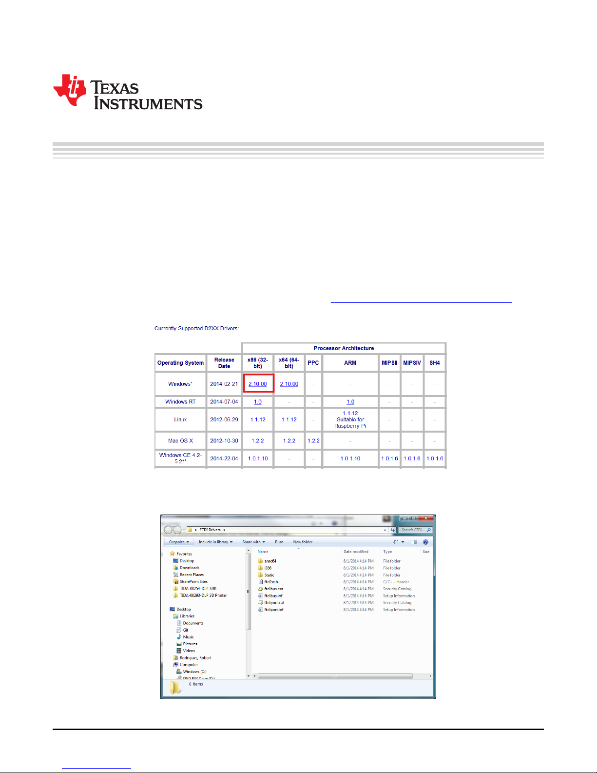
1. Go to the FTDI D2XX driver download site, located at http://www.ftdichip.com/Drivers/D2XX.htm and
download the 32-bit Windows, as shown in Figure 2-1.
2. Extract the downloaded .zip file into a convenient folder, as shown in Figure 2-2.
DLPU025–September 2014 Installing the DLP®3D Printer Reference Design
Submit Documentation Feedback
Figure 2-1. FTDI D2XX Download
Figure 2-2. Extracted FTDI Driver Files
9
Copyright © 2014, Texas Instruments Incorporated
Page 10
Future Technology Devices International D2XX Driver Installation
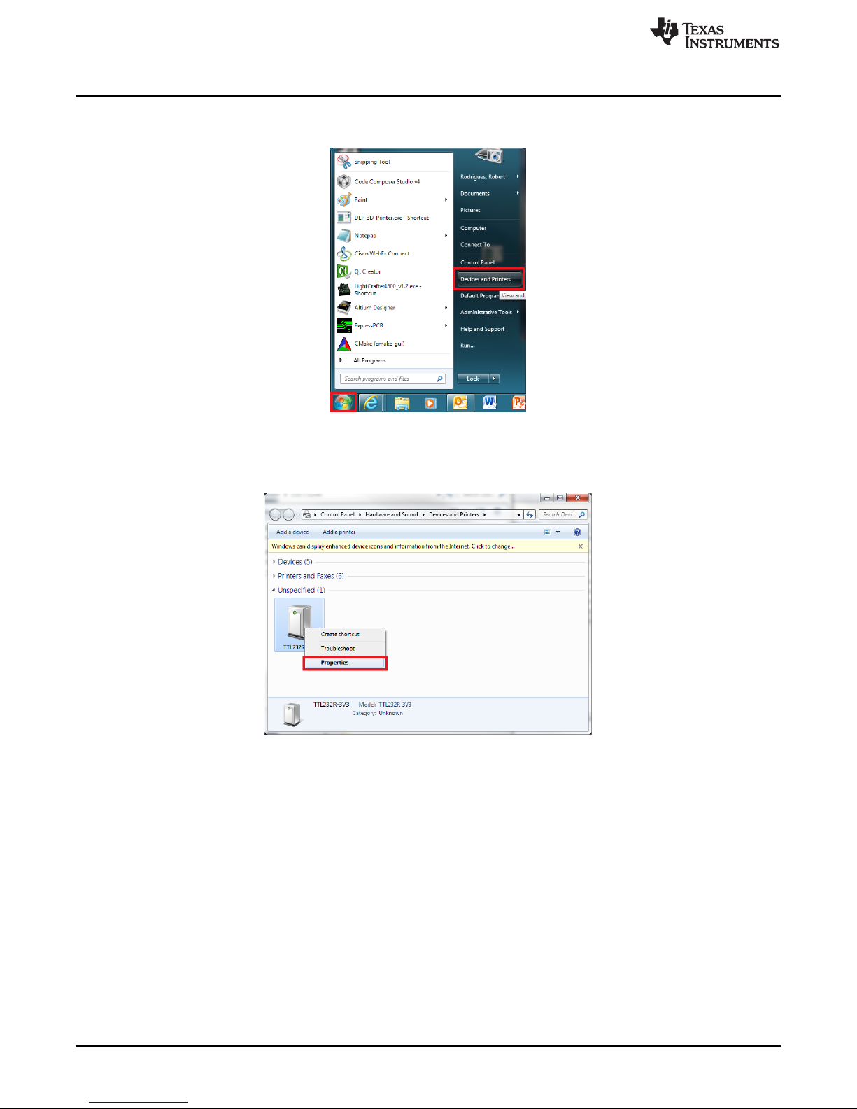
3. After extraction of the driver files, click the Windows button and open Devices and Printers, as shown
in Figure 2-3.
Figure 2-3. Devices and Printers In The Windows Start Bar
4. Find the device labeled TTL232R-3V3 in the list of devices attached to the computer. Right click the
device, and select Properties, as shown in Figure 2-4.
www.ti.com
Figure 2-4. TTL-232R-3V3 Properties Menu
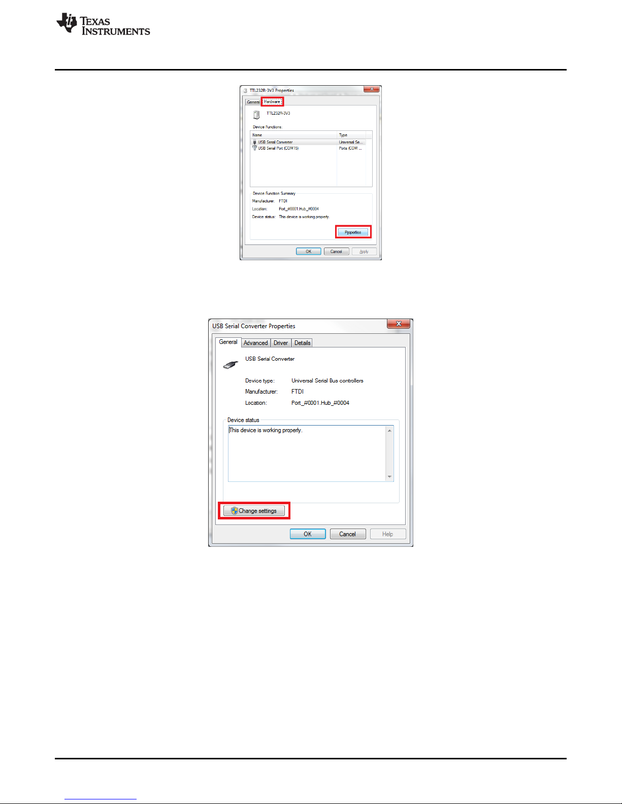
5. Enter the Hardware tab and click the Properties button, shown in Figure 2-5.
10
Installing the DLP®3D Printer Reference Design DLPU025–September 2014
Copyright © 2014, Texas Instruments Incorporated
Submit Documentation Feedback
Page 11
www.ti.com
6. Click the Change Settings button, highlighted in Figure 2-6. Click Yes on the prompt for administrator
Future Technology Devices International D2XX Driver Installation
Figure 2-5. Hardware Properties Button
privileges.
Figure 2-6. Change Settings Button For Hardware Properties
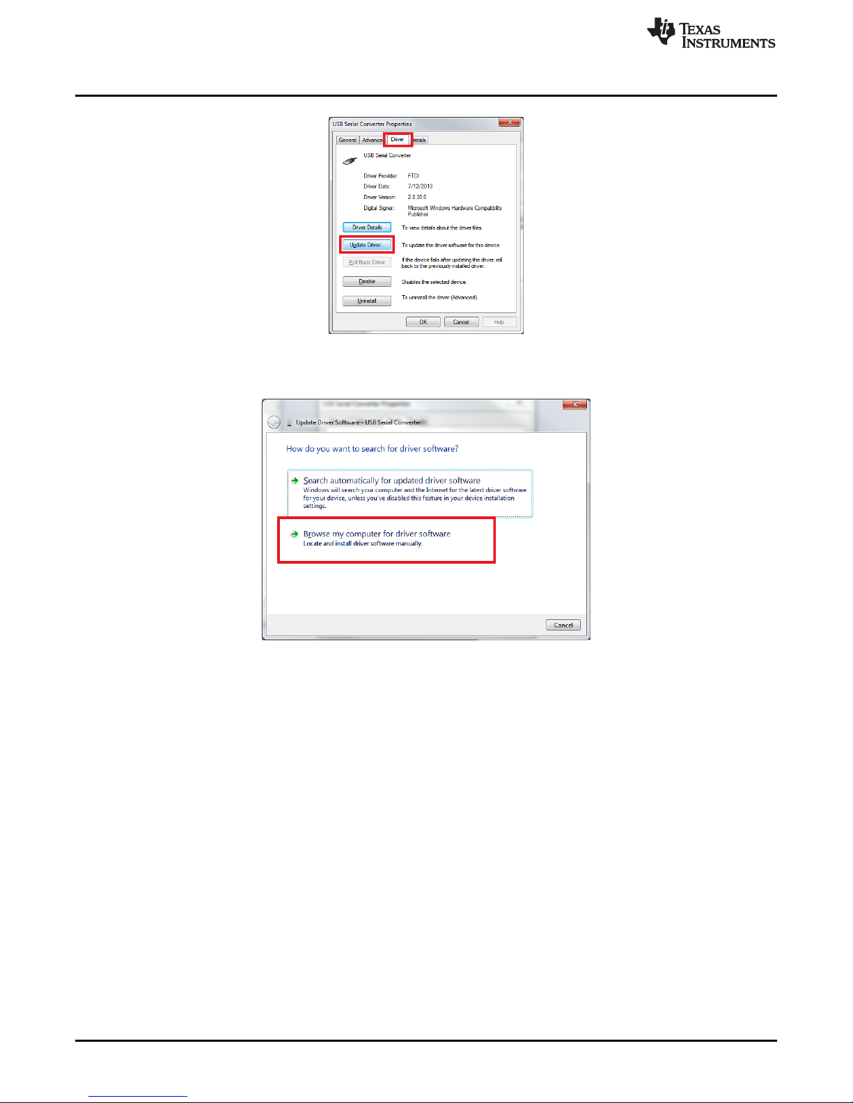
7. Enter the Driver tab, and click the Update Driver button, as shown in Figure 2-7.
DLPU025–September 2014 Installing the DLP®3D Printer Reference Design
Submit Documentation Feedback
11
Copyright © 2014, Texas Instruments Incorporated
Page 12
Future Technology Devices International D2XX Driver Installation
Figure 2-7. Update Driver Option
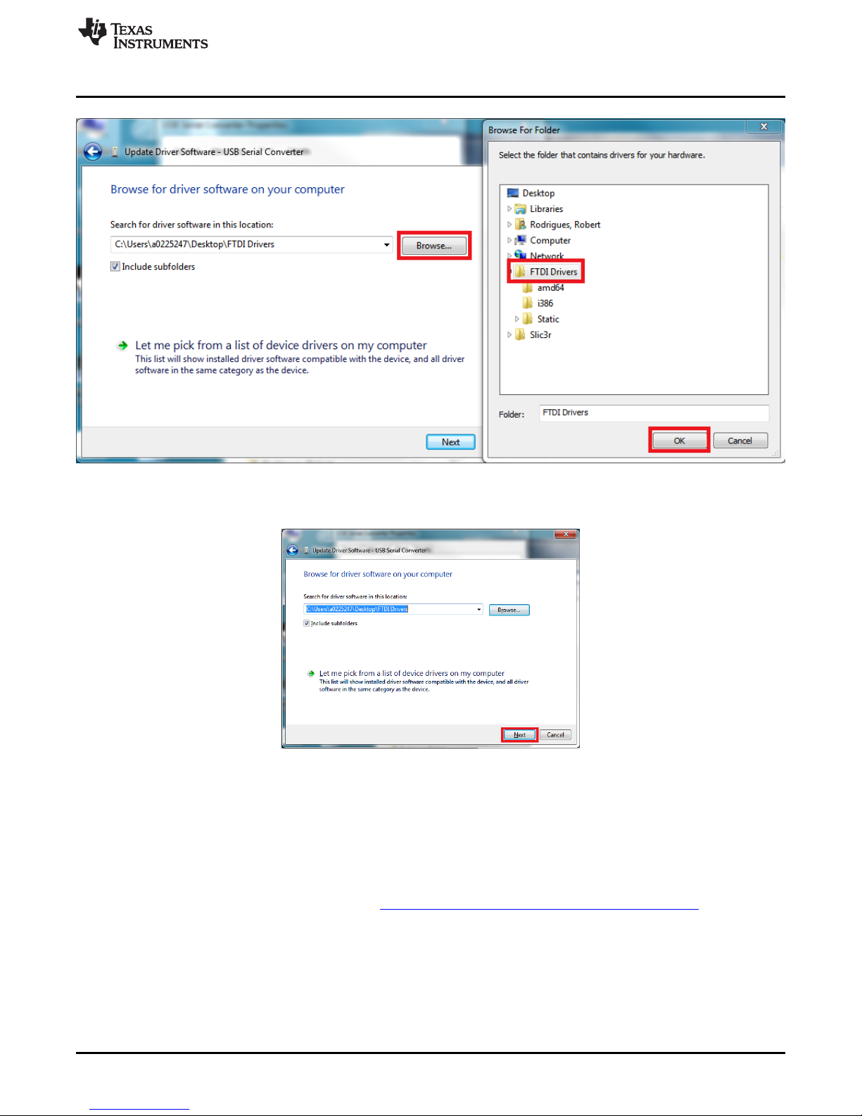
8. Click the Browse my computer option, shown in Figure 2-8.
www.ti.com
Figure 2-8. Browse Computer For Driver Files
9. Click the Browse button that is highlighted in Figure 2-9. Select the folder containing the extracted
driver files from step 2, then click the OK button, as shown in Figure 2-9.
12
Installing the DLP®3D Printer Reference Design DLPU025–September 2014
Copyright © 2014, Texas Instruments Incorporated
Submit Documentation Feedback
Page 13
www.ti.com
Downloading the DLP 3D Printer Reference Design
Figure 2-9. Select Driver File Folder
10. Click the Next button, shown in Figure 2-10.
Figure 2-10. Begin The Update Of Drivers
11. Windows will select the proper drivers from the extracted files and install them. The FTDI D2XX driver
installation is complete. Close all associated windows.
2.3 Downloading the DLP 3D Printer Reference Design
Compiled binaries for the DLP 3D Printer Reference Design are offered for convenience if the user does
not want to build them from source. The binaries are distributed along with the source code in a single
executable file which can be downloaded from the Texas Instruments Reference Design site. The source
code and pre-built program are distributed with the TI Design files in a .zip package.
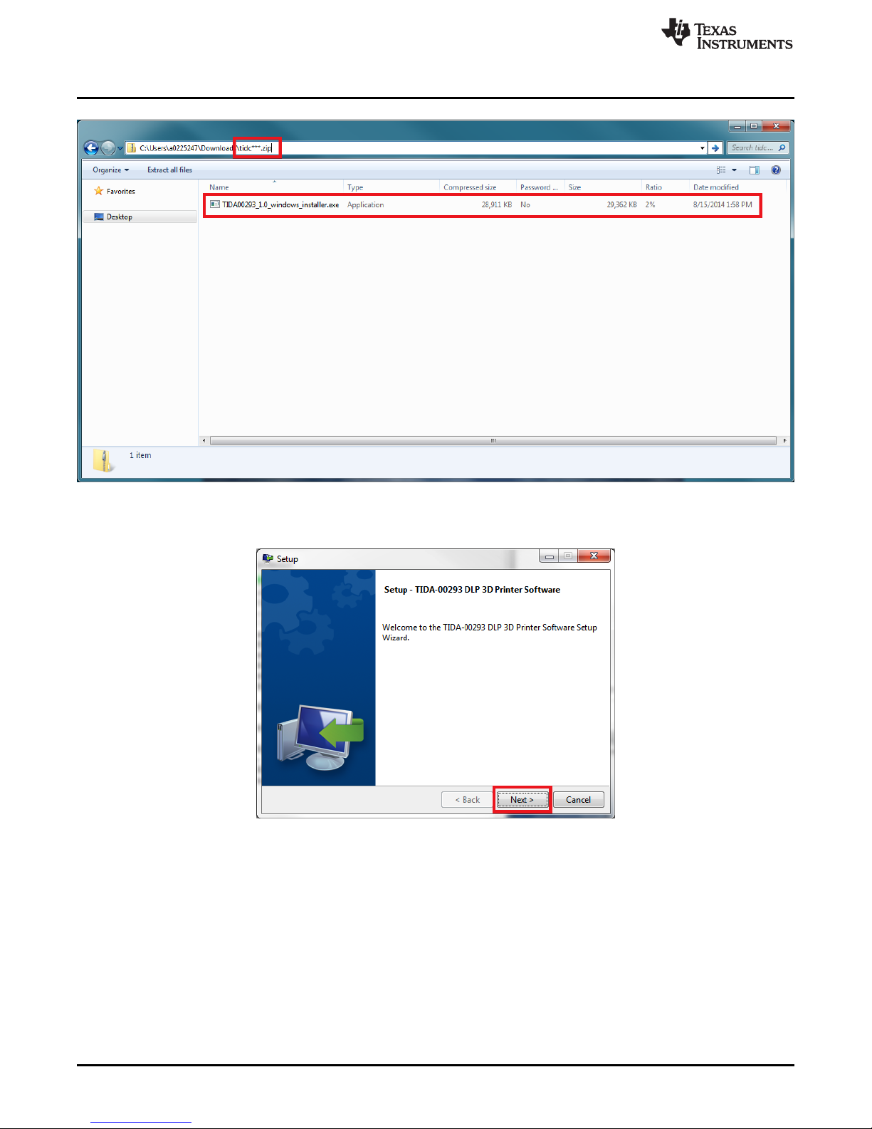
2.4 Installing the DLP 3D Printer Reference Design
1. Decompress the "tidc***.zip" file in a convenient location.
2. Install the DLP 3D Printer Reference Design by executing the file "TIDA00293-***-windowsinstaller.exe," as shown in Figure 2-11.
DLPU025–September 2014 Installing the DLP®3D Printer Reference Design
Submit Documentation Feedback
13
Copyright © 2014, Texas Instruments Incorporated
Page 14
Installing the DLP 3D Printer Reference Design
Figure 2-11. DLP 3D Printer Reference Design Installation Executable
www.ti.com
3. Click the Next button on the install wizard setup screen, as shown in Figure 2-12.
Figure 2-12. DLP 3D Printer Reference Design Setup Wizard Screen
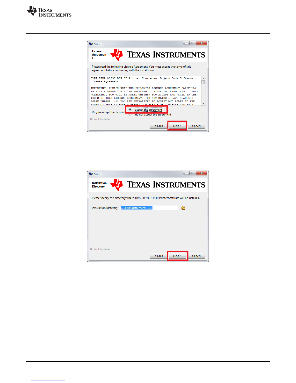
4. Read and review the license agreement for the DLP 3D Printer Reference Design, as shown in
Figure 2-13. Click the I accept the agreement radio button and then click the Next button to continue
installing the software.
14
Installing the DLP®3D Printer Reference Design DLPU025–September 2014
Copyright © 2014, Texas Instruments Incorporated
Submit Documentation Feedback
Page 15
www.ti.com
5. Select an installation path where the reference design software will be located. Click the Next button,
Installing the DLP 3D Printer Reference Design
Figure 2-13. DLP 3D Printer Reference Design License Agreement Screen
as shown in Figure 2-14. Click the Next button to continue installing the software. Warning: Do not
include any spaces in the installation path for the reference design. Spaces will cause errors if the
software is built from source as described in Chapter 4!
Figure 2-14. DLP 3D Printer Reference Design Installation Path Selection
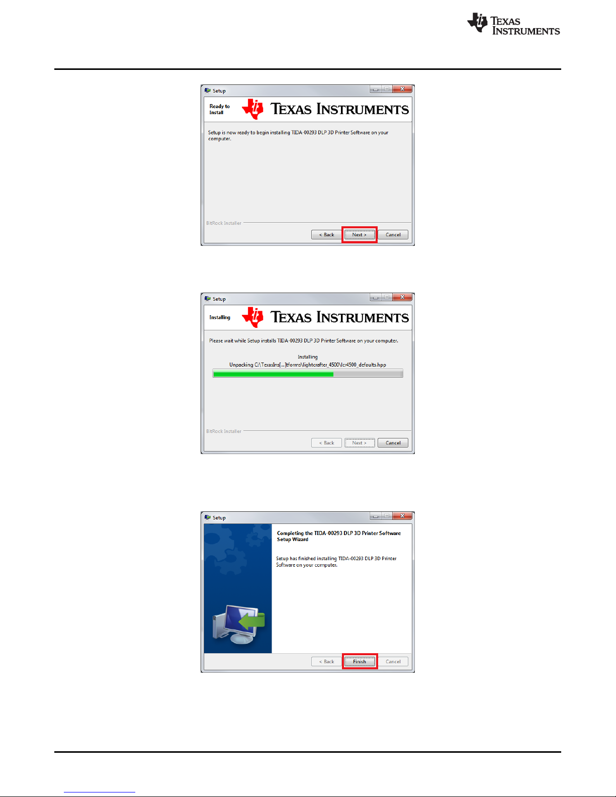
6. The installer is ready to install, click the Next button to start the process, as shown in Figure 2-15.
DLPU025–September 2014 Installing the DLP®3D Printer Reference Design
Submit Documentation Feedback
15
Copyright © 2014, Texas Instruments Incorporated
Page 16
Installing the DLP 3D Printer Reference Design
Figure 2-15. DLP 3D Printer Reference Design Installation Confirmation
7. Wait for the files to install in the location specified, as shown in Figure 2-16.
www.ti.com
Figure 2-16. DLP 3D Printer Reference Design File Installation Progress
8. Once the files have been extracted and installed, click the Finish button to close the installer, as
shown in Figure 2-17.
Figure 2-17. DLP 3D Printer Reference Design Installation Completion
16
Installing the DLP®3D Printer Reference Design DLPU025–September 2014
Copyright © 2014, Texas Instruments Incorporated
Submit Documentation Feedback
Page 17

Chapter 3
DLPU025–September 2014
Using the DLP®3D Printer Reference Design
3.1 The DLP 3D Printer Reference Design application allows users to upload images that represent the cross-
sectional layers of a 3-dimensional object. The layers can be generated in a few methods including by
hand, automatically through a CAD utility, or a specific slicing tool designed for cutting a 3-dimensional
model into layers. Freesteel Slicer was used and can be found here:
http://www.freesteel.co.uk/wpblog/slicer/.
3.2 Programming The MSTP Cape
This section demonstrates how the DLP 3D Printer firmware is uploaded to the MSP430 on the MSTP
Cape. This method requires an MSP-FET430UIF JTAG debugging tool and Code Composer Studio v4 or
later.
1. Connect the MSP-FET430UIF ribbon cable to J5 of the BeagleBone MSTP cape.
2. Connect the MSP-FET430UIF USB connector to the PC loaded with Code Composer Studio v4 or
later.
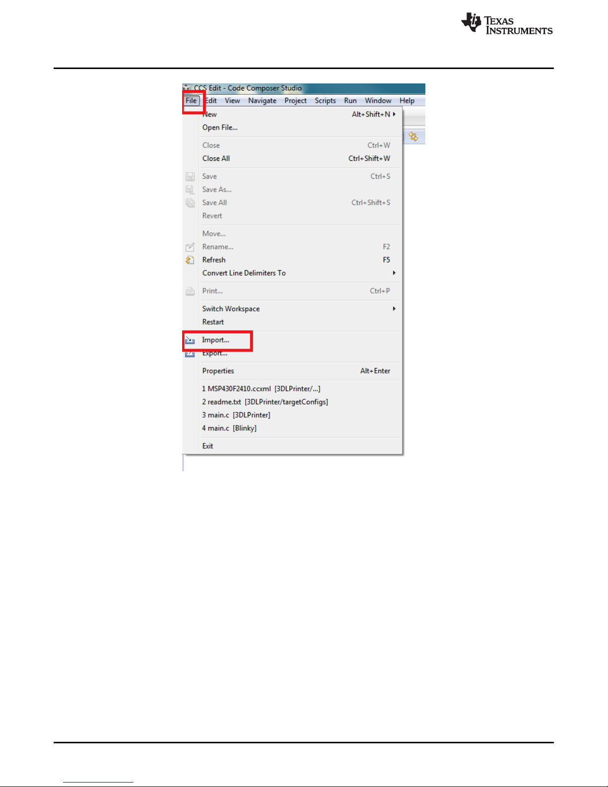
3. Run Code Composer Studio.
4. Click the File tab in the menu bar, then click Import... as shown in Figure 3-1.
DLPU025–September 2014 Using the DLP®3D Printer Reference Design
Submit Documentation Feedback
17
Copyright © 2014, Texas Instruments Incorporated
Page 18
Programming The MSTP Cape
www.ti.com
Figure 3-1. Importing The DLP 3D Printer Firmware Project
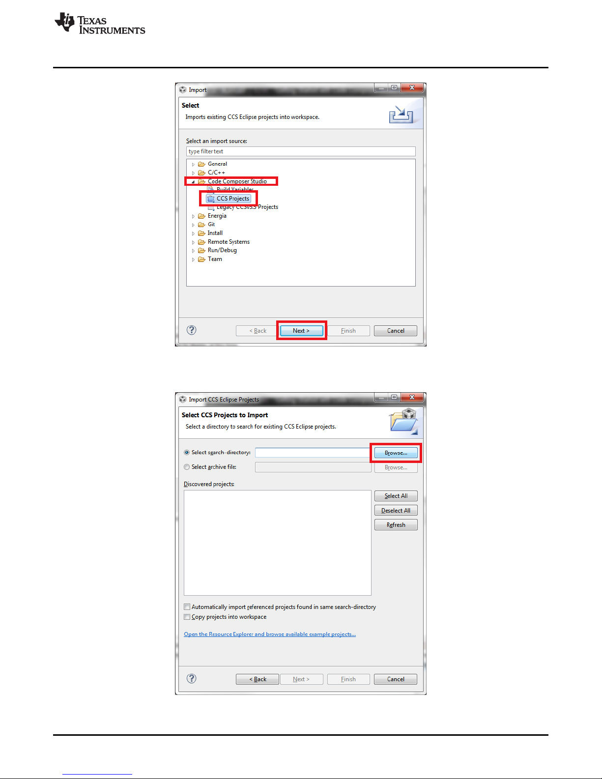
5. Expand the Code Composer Studio folder then click the CCS Projects item, as shown in Figure 3-2.
18
Using the DLP®3D Printer Reference Design DLPU025–September 2014
Copyright © 2014, Texas Instruments Incorporated
Submit Documentation Feedback
Page 19
www.ti.com
Programming The MSTP Cape
Figure 3-2. CCS Project Import Source Selection
6. Click the Browse... button next to the search directory box, as shown in Figure 3-3.
Figure 3-3. CCS Project Importation Search
DLPU025–September 2014 Using the DLP®3D Printer Reference Design
Submit Documentation Feedback
19
Copyright © 2014, Texas Instruments Incorporated
Page 20

Programming The MSTP Cape
7. Select the folder "DLP_3D_Printer_Firmware" located in the TIDA-00293 Software installation path, as
shown in Figure 3-4, then click the OK button.
Figure 3-4. DLP 3D Printer Firmware Project Path Selection
www.ti.com
8. After the project appears in the Discovered projects section, click the Finish button, as shown in
Figure 3-5.
Figure 3-5. DLP 3D Printer Project Importation And Discovery
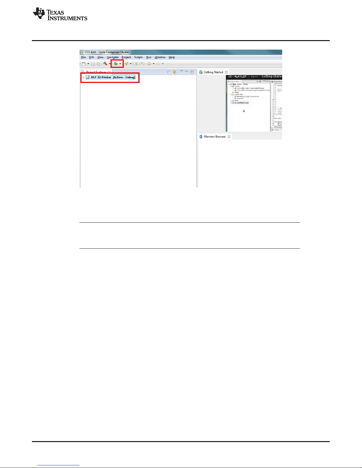
9. The project DLP 3D Printer will display as Active in the Project Explorer window, as shown in
Figure 3-6. Click the start debug button in the toolbar, also shown in Figure 3-6.
20
Using the DLP®3D Printer Reference Design DLPU025–September 2014
Copyright © 2014, Texas Instruments Incorporated
Submit Documentation Feedback
Page 21
www.ti.com
10. Code Composer Studio will build and upload the DLP 3D Printer microcontroller firmware to the
Preparing The Hardware For Printing
Figure 3-6. Uploading the DLP 3D Printer Firmware To The MSTP Cape
MSP430.
NOTE: During the project build and upload process, the user will likely be prompted to upgrade the
firmware on the MSP-FET430UIF. Do not accept the upgrade. Click the Ignore button to
upload the firmware.
11. After the firmware has been uploaded to the MSTP cape, disconnect the the MSP-FET430UIF from
the MSTP cape and reset the cape.
3.3 Preparing The Hardware For Printing
This section describes how to setup the DLP 3D Printer, and connect it to a PC for printing objects. The
instructions from Chapter 2 must be completed prior to these steps.
1. After constructing the hardware for the DLP 3D Printer using the TIDA-00293 design files, the printer
should look similar to Section 2.4.
DLPU025–September 2014 Using the DLP®3D Printer Reference Design
Submit Documentation Feedback
21
Copyright © 2014, Texas Instruments Incorporated
Page 22

Preparing The Hardware For Printing
www.ti.com
2. Place the resin vat in the printer base and place it securely against the alginment tabs, as shown in
Figure 3-8.
22
Using the DLP®3D Printer Reference Design DLPU025–September 2014
Figure 3-7. DLP 3D Printer Built Hardware
Copyright © 2014, Texas Instruments Incorporated
Submit Documentation Feedback
Page 23

www.ti.com
Preparing The Hardware For Printing
Figure 3-8. Resin Vat Placement
3. Secure the vat in place by securing the latches on the base, as shown in Figure 3-9.
4. Connect the TTL-232R-3V3 cable to the RS232 to MSTP Cape Cable Assembly (TI Drawing #
2514179), as shown in Figure 3-10. The black wire from the TTL cable aligns with the single wire pin
DLPU025–September 2014 Using the DLP®3D Printer Reference Design
Submit Documentation Feedback
Figure 3-9. Resin Vat Locked In Position
23
Copyright © 2014, Texas Instruments Incorporated
Page 24

Preparing The Hardware For Printing
on the cable to the printer.
www.ti.com
Figure 3-10. TTL-232R-3V3 Connected To DLP 3D Printer
5. Connect the USB mini connector to the LightCrafter 4500, as shown in Figure 3-11.
Figure 3-11. LightCrafter 4500 USB Connection
24
Using the DLP®3D Printer Reference Design DLPU025–September 2014
Copyright © 2014, Texas Instruments Incorporated
Submit Documentation Feedback
Page 25

www.ti.com
6. Connect both the USB cable from the LightCrafter 4500, and the TTL-232R-3V3 cable to a Windows 7
Preparing The Hardware For Printing
based PC, as shown in Figure 3-12.
Figure 3-12. LightCrafter 4500 And TTL-232R-3V3 Cable Connected To PC
7. Plug the 12 V power supply into the jack on the side of the DLP 3D Printer, as shown in Figure 3-13.
Figure 3-13. Connecting 12 V Power To The Printer
8. The DLP 3D Printer will power up, and the build platform will start to index. The platform will move all
DLPU025–September 2014 Using the DLP®3D Printer Reference Design
Submit Documentation Feedback
25
Copyright © 2014, Texas Instruments Incorporated
Page 26

Preparing The Hardware For Printing
the way down to its limit, then up out of the resin vat. The display will initialize and display the
message shown in Figure 3-14.
www.ti.com
Figure 3-14. DLP 3D Printer Initialization Message
9. Once the build platform has completed its travel -- and is located above the vat -- the LCD will display
the printer's name, as shown in Figure 3-15.
Figure 3-15. DLP 3D Printer Initialized And Waiting
26
Using the DLP®3D Printer Reference Design DLPU025–September 2014
Copyright © 2014, Texas Instruments Incorporated
Submit Documentation Feedback
Page 27

www.ti.com
10. Place a piece of perforated aluminum on the build platform, as shown in Figure 3-16. This step can be
Printing An Object
skipped IF the build platform is created out of aluminum. The photo-resin from www.buy3DInk.com,
tested during this design, had very poor adhesion to stainless steel.
11. The DLP 3D Printer is now ready to accept layer sequences from the PC.
3.4 Printing An Object
This section guides the user through using the DLP 3D Printer GUI to upload layer images to the printer
and start a print sequence. Ensure the steps from Section 3.3 have been completed.
1. Start the DLP 3D Printer Reference Design program, installed in Section 2.4, by running the
executable file, as shown in Figure 3-17.
Figure 3-16. Perforated Aluminum Build Plate In Place
DLPU025–September 2014 Using the DLP®3D Printer Reference Design
Submit Documentation Feedback
27
Copyright © 2014, Texas Instruments Incorporated
Page 28

Printing An Object
www.ti.com
Figure 3-17. Executing The DLP 3D Printer Program
2. The DLP 3D Printer GUI will appear loaded with the default settings. Click the Set button to the right of
the Object Images Folder text box, as shown in Figure 3-18.
28
Using the DLP®3D Printer Reference Design DLPU025–September 2014
Copyright © 2014, Texas Instruments Incorporated
Submit Documentation Feedback
Page 29

www.ti.com
Printing An Object
Figure 3-18. Setting The Image Folder
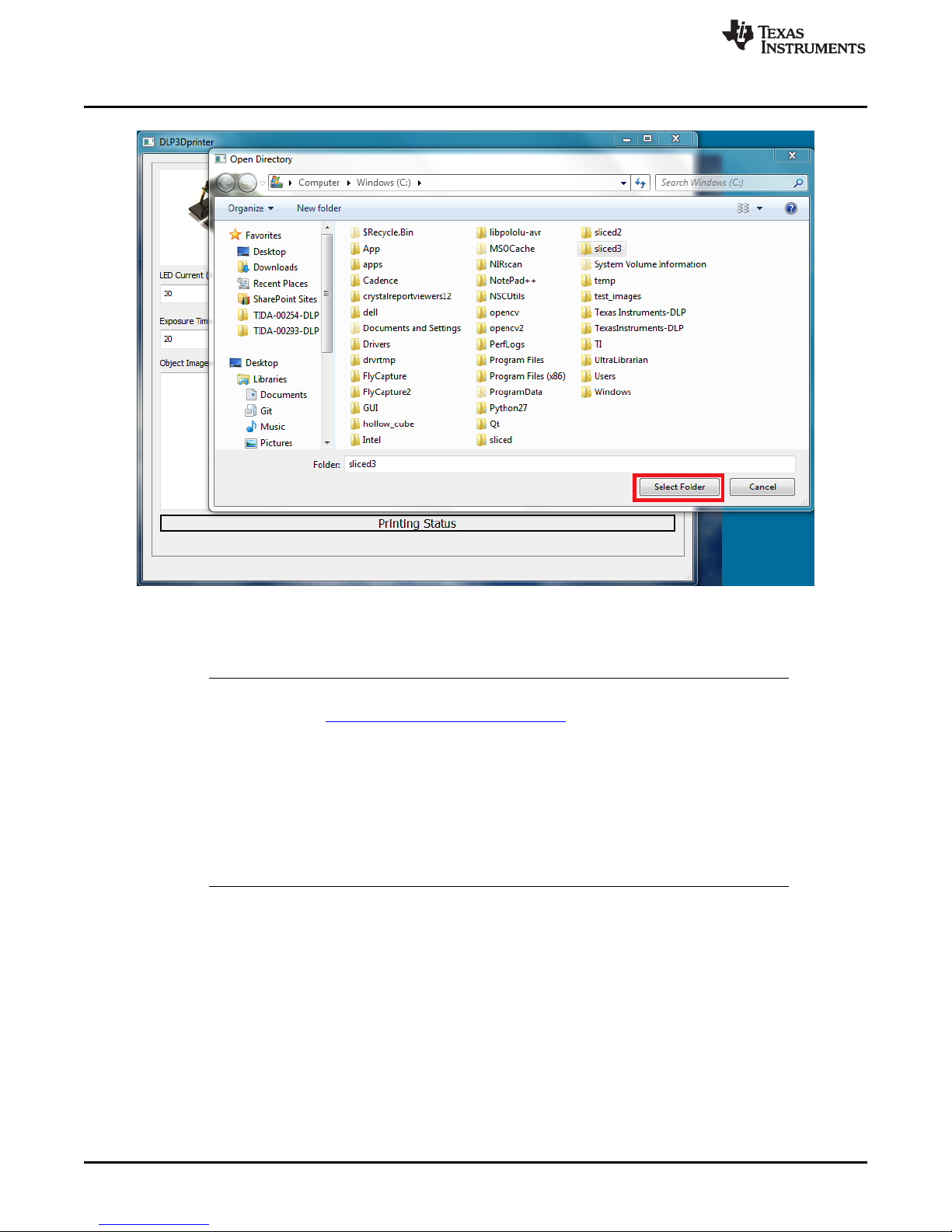
3. In the dialog box, select the folder where the cross-sectional images are located, as shown in Figure 3-
19. Highlight the folder and click the Select Folder button.
NOTE: The layer images must be 912 × 1140 resolution. Best results have been achieved with
BMP images. JPG images may be used, but layer quality will suffer due to lossy
compression methods employed in JPG.
DLPU025–September 2014 Using the DLP®3D Printer Reference Design
Submit Documentation Feedback
29
Copyright © 2014, Texas Instruments Incorporated
Page 30
Printing An Object
www.ti.com
Figure 3-19. Layer Image Folder Selection
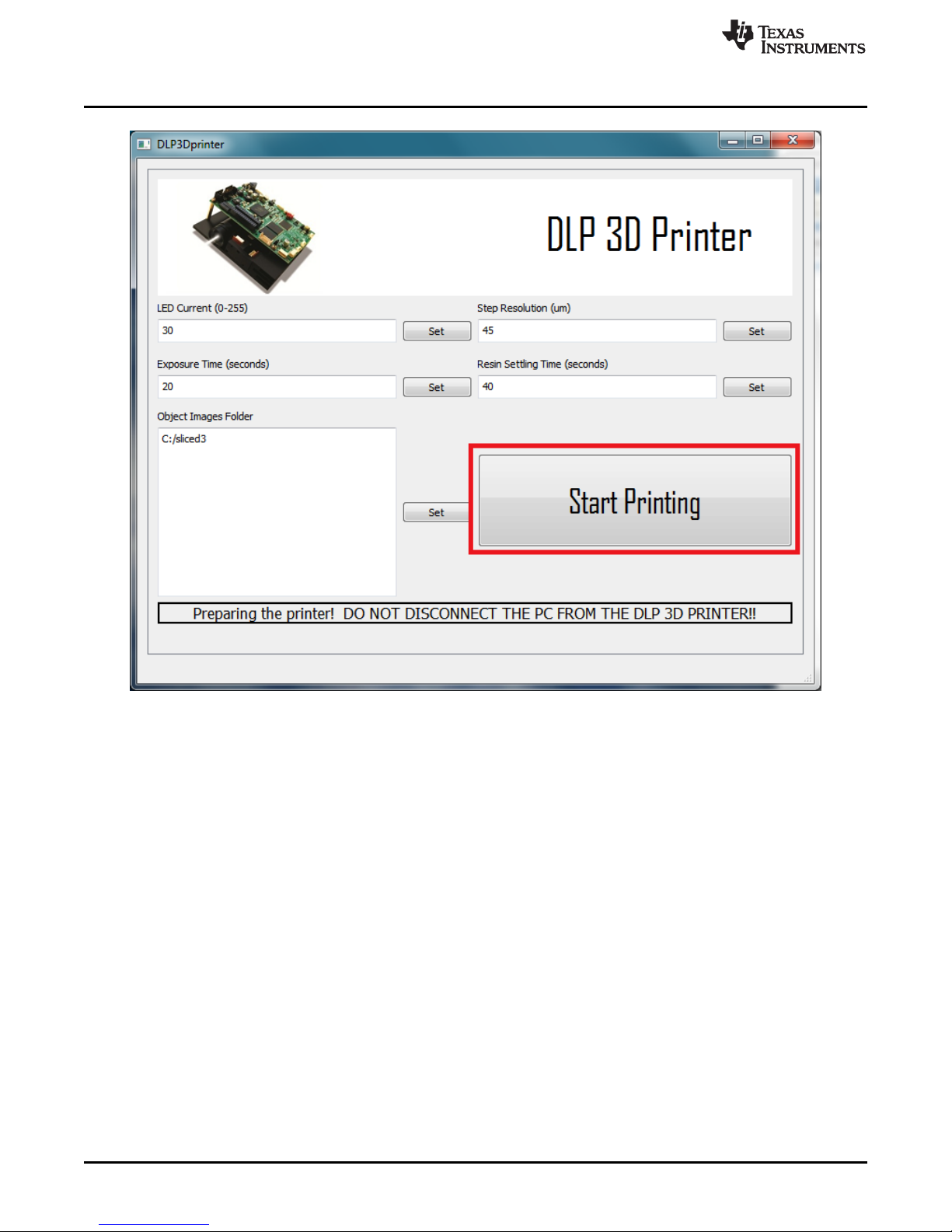
4. After the layer image folder has been selected, double check the settings for the print. The GUI should
look like Figure 3-20.
NOTE: The default settings are derived experimentally with resin produced by 3D Ink™,
purchasable here: http://www.buy3dink.com/p/59/uv-resin
Step resolution should be kept between 30 and 60 microns for best results but can be set
between 5 and 100 microns.
LED current should never be set above 35, and should only be set at 35 when the 420 nm
LED is placed on a metal core PCB.
Exposure time will be driven by a combination of layer thickness and LED current.
Resin settling time is the amount of time required for the resin's surface to return to level
after the build platform has moved.
30
Using the DLP®3D Printer Reference Design DLPU025–September 2014
Copyright © 2014, Texas Instruments Incorporated
Submit Documentation Feedback
Page 31

www.ti.com
Printing An Object
Figure 3-20. Printer Settings Check Before Sending Images To The Printer
5. After verifying the print settings, click the Start Printing button, as shown in Figure 3-21.
DLPU025–September 2014 Using the DLP®3D Printer Reference Design
Submit Documentation Feedback
31
Copyright © 2014, Texas Instruments Incorporated
Page 32
Printing An Object
www.ti.com
Figure 3-21. Starting The Print Sequence
6. The print sequence will take up to 10 minutes to prepare, and upload to, the projector. Do not
disconnect the PC from the DLP 3D Printer or close the GUI during this process. Either could corrupt
the firmware on the LightCrafter 4500. Wait for the message "You may now disconnect the PC from
the DLP 3D Printer" to be displayed, as shown in Figure 3-22.
32
Using the DLP®3D Printer Reference Design DLPU025–September 2014
Copyright © 2014, Texas Instruments Incorporated
Submit Documentation Feedback
Page 33

www.ti.com
Printing An Object
Figure 3-22. Object Layer Image Sequence Upload Completed
7. The DLP 3D Printer will begin to move the build platform down and into the vat, and display the
message shown in Figure 3-23.
DLPU025–September 2014 Using the DLP®3D Printer Reference Design
Submit Documentation Feedback
Figure 3-23. Beginning Of Object Printing
33
Copyright © 2014, Texas Instruments Incorporated
Page 34

Chapter 4
DLPU025–September 2014
Building the DLP®3D Printer Reference Design from
Source
4.1 The DLP 3D Printer Reference Design application's source code is made available in the design files
installed in Chapter 2. The availability of the source allows users to modify, and build, the scanning
application on their own. Complete the installation of the necessary files before attempting to build the
application from source.
4.2 Qt Creator Installation
This section guides the user through the installation of the Qt Creator integrated development environment
(IDE.)
1. Download the Qt Creator IDE from the project webpage located here. Download the 32-bit Windows
version of Qt 5.2.1, or higher, that is bundled with MinGW. Note: This SDK uses C++11 and will not
compile using an out-of-date compiler. Use Qt 5.2.1, or later!
2. Execute the downloaded install file.
3. Click the Next button as shown in Figure 4-1.
34
Building the DLP®3D Printer Reference Design from Source DLPU025–September 2014
Figure 4-1. Qt Creator IDE Installation
Copyright © 2014, Texas Instruments Incorporated
Submit Documentation Feedback
Page 35

www.ti.com
4. Select an installation path for the Qt IDE. Click the Next button as seen in Figure 4-2.
5. Choose the install components as shown in Figure 4-3. Make sure that MinGW is selected and click
Qt Creator Installation
Figure 4-2. Qt Creator IDE Installation Path Selection
the Next button.
Figure 4-3. Qt Creator IDE Installation Component Selection
DLPU025–September 2014 Building the DLP®3D Printer Reference Design from Source
Submit Documentation Feedback
35
Copyright © 2014, Texas Instruments Incorporated
Page 36

Qt Creator Installation
6. Review the license agreement and indicate you agree with the terms, shown in Figure 4-4. Then click
the Next button.
www.ti.com
Figure 4-4. Qt Creator IDE End User License Agreement
7. Click the Next button as shown in Figure 4-5.
Figure 4-5. Qt Creator IDE Ready To Install
36
Building the DLP®3D Printer Reference Design from Source DLPU025–September 2014
Copyright © 2014, Texas Instruments Incorporated
Submit Documentation Feedback
Page 37

www.ti.com
8. Wait for the installation to complete. Figure 4-6 shows the installation status bar.
Qt Creator Installation
Figure 4-6. Qt Creator IDE Installing
9. Once the Qt IDE installation has completed, click the Finish button as shown in Figure 4-7.
Figure 4-7. Qt IDE Installation Completed
DLPU025–September 2014 Building the DLP®3D Printer Reference Design from Source
Submit Documentation Feedback
37
Copyright © 2014, Texas Instruments Incorporated
Page 38

Qt Creator Installation
10. Using Windows Explorer, navigate to the Qt installation location and find the MinGW binary location.
Copy the path as shown in Figure 4-8.
www.ti.com
Figure 4-8. Finding the MinGW Installation Path
38
Building the DLP®3D Printer Reference Design from Source DLPU025–September 2014
Copyright © 2014, Texas Instruments Incorporated
Submit Documentation Feedback
Page 39

www.ti.com
11. Click the Windows button and type "edit the system environment" into the search box, shown in
Qt Creator Installation
Figure 4-9. Click the option labeled "Edit the system environment variables".
Figure 4-9. System Environment Variables Editing
12. Click the Environment Variables... button in the lower right corner, shown in Figure 4-10.
DLPU025–September 2014 Building the DLP®3D Printer Reference Design from Source
Submit Documentation Feedback
Figure 4-10. System Properties Window
39
Copyright © 2014, Texas Instruments Incorporated
Page 40
Qt Creator Installation
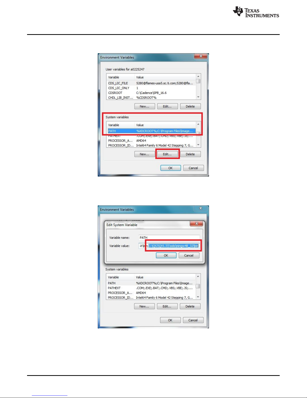
13. In the System variables section, browse to the entry labeled PATH. Highlight the entry and click the
Edit button, shown in Figure 4-11.
www.ti.com
Figure 4-11. Editing the PATH Variable
14. Insert the path to the MinGW compiler binary directory in the PATH variable as shown in Figure 4-12,
then click the OK button. Note: Make sure that the entries are separated by a semicolon.
Figure 4-12. MinGW Directory Added to the PATH Variable
15. Click the OK button for the System properties window, then restart your computer. The installation of
the Qt IDE and MinGW is now complete.
40
Building the DLP®3D Printer Reference Design from Source DLPU025–September 2014
Copyright © 2014, Texas Instruments Incorporated
Submit Documentation Feedback
Page 41

www.ti.com
4.3 OpenCV Build and Installation
This section details the steps taken to build the OpenCV libraries required for MinGW from the OpenCV
source files. Careful attention must be paid in this section for a successful build.
1. Download the OpenCV Version 2.4.6, or higher, Windows installation from http://opencv.org/.
2. Download the Cmake Version 2.8.12.2, or higher, Windows (Win32 Installer) from
http://www.cmake.org/cmake/resources/software.html.
3. Run the downloaded OpenCV file and click on the Extract button, shown in Figure 4-13.
Figure 4-13. OpenCV Source Extraction Path
4. Wait for the OpenCV libraries and source files to install. The installation path is shown in Figure 4-14.
OpenCV Build and Installation
Figure 4-14. OpenCV Source Extraction
5. Run the Cmake installation program downloaded in step 2. Click the Next button as shown in Figure 4-
15.
Figure 4-15. Cmake Installation Entry
DLPU025–September 2014 Building the DLP®3D Printer Reference Design from Source
Submit Documentation Feedback
41
Copyright © 2014, Texas Instruments Incorporated
Page 42

OpenCV Build and Installation
6. Review the end-user license agreement for Cmake and accept the terms to continue with the
installation. The license agreement is higlighted in Figure 4-16.
7. Accept the default settings for the Cmake installation. Select Do not add Cmake to the system PATH
variable as shown in Figure 4-17.
www.ti.com
Figure 4-16. Cmake User License Agreement
8. Choose an installation path for Cmake. Click the Next button, highlighted in Figure 4-18.
42
Building the DLP®3D Printer Reference Design from Source DLPU025–September 2014
Figure 4-17. Cmake Installation Options
Figure 4-18. Cmake Installation Path
Copyright © 2014, Texas Instruments Incorporated
Submit Documentation Feedback
Page 43

www.ti.com
9. Once the Cmake installation is complete, click the Finish button highlighted in Figure 4-19.
10. Search for, and run, the Cmake GUI that was installed in the previous step, an example of finding it is
OpenCV Build and Installation
Figure 4-19. Cmake Installation Completed
shown in Figure 4-20.
Figure 4-20. Cmake GUI Execution From Windows Start Button
DLPU025–September 2014 Building the DLP®3D Printer Reference Design from Source
Submit Documentation Feedback
43
Copyright © 2014, Texas Instruments Incorporated
Page 44
OpenCV Build and Installation
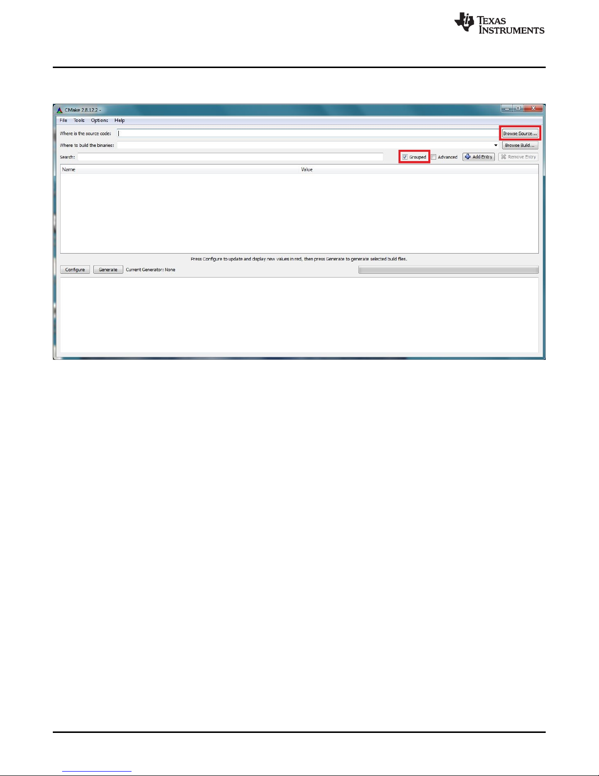
11. Inside of the Cmake GUI, check the box labeled "Grouped." Then click the Browse Source... button
highlighted in Figure 4-21.
www.ti.com
Figure 4-21. Cmake GUI Source Selection
44
Building the DLP®3D Printer Reference Design from Source DLPU025–September 2014
Copyright © 2014, Texas Instruments Incorporated
Submit Documentation Feedback
Page 45

www.ti.com
12. Browse to the /opencv/sources folder installed in step 3. Click the /sources folder as highlighted in
OpenCV Build and Installation
Figure 4-22, then click the OK button.
Figure 4-22. OpenCV Source Selection In Cmake
DLPU025–September 2014 Building the DLP®3D Printer Reference Design from Source
Submit Documentation Feedback
45
Copyright © 2014, Texas Instruments Incorporated
Page 46

OpenCV Build and Installation
13. Click the Browse Build... button and select a path for the built libraries to be installed, shown in
Figure 4-23.
www.ti.com
Figure 4-23. Cmake GUI Build Selection
14. Click the Configure button in the Cmake GUI, highlighted in Figure 4-24.
46
Building the DLP®3D Printer Reference Design from Source DLPU025–September 2014
Figure 4-24. Cmake GUI Configure Build
Copyright © 2014, Texas Instruments Incorporated
Submit Documentation Feedback
Page 47

www.ti.com
15. A window will appear prompting the user to select the compilers to make the OpenCV libraries for.
OpenCV Build and Installation
Select MinGW makefiles from the drop down list, and select use default native compilers radio button.
The correct selections are highlighted in Figure 4-25. Click the Finish button.
Figure 4-25. Cmake Compiler Configuration
DLPU025–September 2014 Building the DLP®3D Printer Reference Design from Source
Submit Documentation Feedback
47
Copyright © 2014, Texas Instruments Incorporated
Page 48

OpenCV Build and Installation
16. Cmake uses the instruction files located in the OpenCV source directory to configure build options.
This step may take a while and should complete with no errors in the lower status window as shown in
Figure 4-26. Note: If an error occurs immediately, check the PATH variable and ensure that the
directory to the MinGW compilers is correct, and the computer was restarted to make the changes
take effect.
www.ti.com
Figure 4-26. Cmake Install Option Configuration
48
Building the DLP®3D Printer Reference Design from Source DLPU025–September 2014
Copyright © 2014, Texas Instruments Incorporated
Submit Documentation Feedback
Page 49

www.ti.com
17. Cmake will provide the user with a host of options for the OpenCV build. The options will appear in
OpenCV Build and Installation
red before they are accepted by Cmake. Expand the group called CMAKE and find the variable
named CMAKE_BUILD_TYPE, as shown in Figure 4-27. Populate the empty Value box next to
CMAKE_BUILD_TYPE with "Release" then click the Configure button. All the options should turn
white, and no errors should be reported in the lower status window.
Figure 4-27. Cmake Build Options Input
18. Cmake is ready to create the make file for building OpenCV. Once all options are white in the option
window, click the Generate button shown in Figure 4-28.
DLPU025–September 2014 Building the DLP®3D Printer Reference Design from Source
Submit Documentation Feedback
Figure 4-28. Cmake Make File Generation
49
Copyright © 2014, Texas Instruments Incorporated
Page 50

OpenCV Build and Installation
19. Once Cmake has completed generating the make file, click the Windows button to open the Start bar.
Open a command line window by typing "cmd" into the Window's search bar inside the Windows Start
button, as shown in Figure 4-29.
www.ti.com
Figure 4-29. Opening a Command Line Window
50
Building the DLP®3D Printer Reference Design from Source DLPU025–September 2014
Copyright © 2014, Texas Instruments Incorporated
Submit Documentation Feedback
Page 51

www.ti.com
20. Navigate to the OpenCV build path that was given to Cmake in step 13. From this path, run the
21. Depending on your system specifications, this process could take from 1 hour to 6 hours. Allow the
OpenCV Build and Installation
command "mingw32-make" as shown in Figure 4-30. Note: If the command "mingw32-make" is not
recognized, try using the command "make." This is dependent on the naming of the make.exe file
installed with Qt Creator.
Figure 4-30. Starting the OpenCV Build Process
build to complete normally, as shown in Figure 4-31.
22. After the mingw32-make command has finished running, the built libraries must be installed. Run the
command "mingw32-make install" as shown in Figure 4-32.
Figure 4-32. Installing the OpenCV Libraries
DLPU025–September 2014 Building the DLP®3D Printer Reference Design from Source
Submit Documentation Feedback
Figure 4-31. Long OpenCV Build Process
51
Copyright © 2014, Texas Instruments Incorporated
Page 52
DLP 3D Printer Reference Design Project File Setup
23. After the install command has executed in the command line window, the window may be closed.
OpenCV is now built and installed.
4.4 DLP 3D Printer Reference Design Project File Setup
After the design environment has been prepared, changes need to be made in the .pro file to reflect the
location of the installation of the OpenCV libraries.
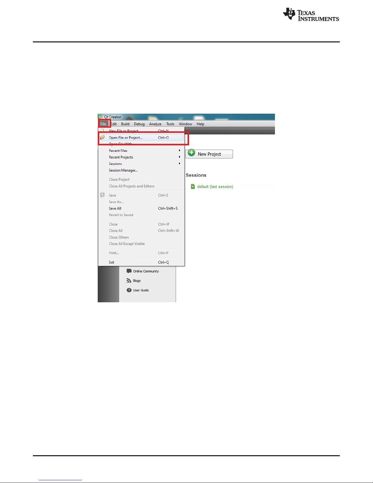
1. Open the Qt Creator IDE and click the File menu option in the upper left hand corner. Click Open File
or Project... shown in Figure 4-33.
www.ti.com
Figure 4-33. Opening the DLP 3D Printer Reference Design Project In Qt Creator
2. Navigate to, and open, the file named "DLP_3D_Printer_GUI.pro" in the DLP 3D Printer Software
install path, as shown in Figure 4-34.
52
Building the DLP®3D Printer Reference Design from Source DLPU025–September 2014
Copyright © 2014, Texas Instruments Incorporated
Submit Documentation Feedback
Page 53

www.ti.com
DLP 3D Printer Reference Design Project File Setup
Figure 4-34. QT .pro File Location
3. Click the Projects tab on the left of the Qt IDE and click Configure Project tab on the top bar, as
shown in Figure 4-35. Then click the Configure Project button also shown in Figure 4-35.
Figure 4-35. Configuring the QT .pro for Building
4. Click the Edit tab on the left of the Qt IDE, and in the projects view box, open the file named
"DLP_3D_Printer_GUI.pro", shown in Figure 4-36, to edit its contents.
DLPU025–September 2014 Building the DLP®3D Printer Reference Design from Source
Submit Documentation Feedback
53
Copyright © 2014, Texas Instruments Incorporated
Page 54

DLP 3D Printer Reference Design Project File Setup
Figure 4-36. Opening the QT .pro for Editing
5. In the top section of the project file, edit the OpenCV include path, the MinGW binary path, and the
FTDI driver path to the proper directories. The paths that require setting are highlighted in Figure 4-37 ,
blocks 1, 2 and 3 respectively. No settings should be changed below the block titled Do not change
code below.
Note: The OpenCV path will contain two separate include directories. The correct directory will be
located inside the opencv/install/ OR opencv/build/ folder, not inside the opencv/ directory.
Note: The OpenCV version number built must be changed as well. If the directions in this guide were
followed explicitly, the build number has the letter "d" appended to the end, indicating a debug build.
Check the libraries in the OpenCV lib directory for the proper version number appended to all the file
names.
Note: The FTDI headers are located in the initial extraction path used in step 2 of Section 2.2.
www.ti.com
Figure 4-37. Editing The Include Paths For OpenCV and FTDI Libraries
6. The project may now be built by clicking the Run or Build button in the lower left hand corner, as
shown in Figure 4-38.
54
Building the DLP®3D Printer Reference Design from Source DLPU025–September 2014
Copyright © 2014, Texas Instruments Incorporated
Submit Documentation Feedback
Page 55

www.ti.com
7. The DLP 3D Printer GUI program may now be run from the Qt Creator IDE or from EXE file in the
DLP 3D Printer Reference Design Project File Setup
Figure 4-38. Running The DLP 3D Printer Reference Design GUI
source code path. Refer to Chapter 3 for directions on using the DLP 3D Printer program.
DLPU025–September 2014 Building the DLP®3D Printer Reference Design from Source
Submit Documentation Feedback
55
Copyright © 2014, Texas Instruments Incorporated
Page 56

Chapter 5
DLPU025–September 2014
DLP®3D Printer Design Considerations
5.1 The DLP 3D Printer is designed for ease of use and modification in the future. The design is not intended
to be a total end product. This section describes some of the design decisions that were made, and
aspects of the design that can be adjusted to tailor the printer to specific end-user applications.
5.2 Hardware Design
The hardware design section encompasses the physical aspects of the DLP 3D Printer design.
5.2.1 Illumination Source
The DLP 3D Printer utilizes a 420 nanometer light emitting diode made by Philips Lumileds. The emitter is
a 675 mW rated LED with a dominant wavelength between 420 and 425 nm. The emitter was selected for
easy, drop-in replacement in the LightCrafter 4500 light engine. The majority of the 420 nm emitter's
output falls inside the operational specification of the LightCrafter 4500, extending the operating life of the
DLP4500 DMD.
The emitter is hosted on an FR-4 printed circuit board. The design file for the board can be found in the TI
Design file path: ..\Design Files\LightCrafter 4500 Modifications\. The host board file is viewable by the
ExpressPCB freeware. Applications notes for the emitter from Philips indicate the emitter should be hosted
on a metal core PCB for maximum thermal efficiency. Note: Placement of the LED on the FR-4 board
requires a derating of emitter current to increase emitter life-span.
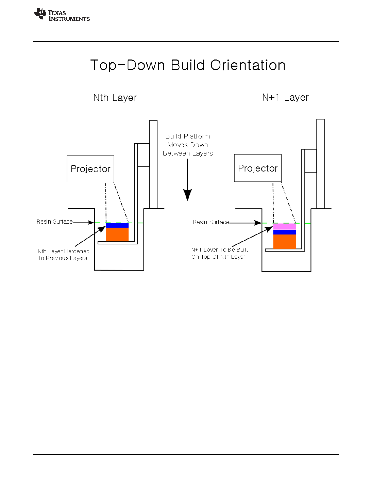
5.2.2 Build Orientation
The DLP 3D Printer is built for a top-down projection method. The top-down projection method builds
objects inside of the resin vat by lowering the build platform into the resin. The top-down build method
simplifies certain design considerations but has drawbacks. The 3D Printer reference design could be
modified for a bottom projection method with minimal code and hardware changes.
The top-down build method has it's layer thickness defined by the distance from the build platform -- or
partially-built object -- and the upper surface of the resin. This means consideration must be taken for the
time it takes the resin's surface layer to return to level after build platform movements. The DLP 3D Printer
design takes this into account by delaying a user-defined "resin settling time." Resin settling time can be
significant and dominate the total layer build time. A second item to consider with the top-down build
approach is the requirement for the printer to sit on a level surface in order to keep the resin level -defined by gravity -- parallel with the build platform. Strengths of the top-down build method include
mechanical simplicity and less maintenance of the printer. The top-down build method is visualized in
Figure 5-1.
56
DLP®3D Printer Design Considerations DLPU025–September 2014
Copyright © 2014, Texas Instruments Incorporated
Submit Documentation Feedback
Page 57
www.ti.com
Hardware Design
The bottom-up build method is more popular as it solves two key issues: resin settling time and layer
thickness control. The bottom-up build orientation requires the projected layer images to be transmitted
through a material into the resin vat from below. The build platform starts flush against the transmissive
window and steps upward with each layer. The build platform's orientation to the window means the
resin's surface does not impact the build, and the layer thickness is clearly defined between the platform
and the window. The bottom-up build requires a smaller volume of resin in the vat at a time but requires
the user to constantly refill the vat as resin is used. The challenge of stiction also exists between the
hardened layers and the transmissive window. The solidified resin should separate cleanly, and easily,
from the transmissive window or else delicate features may be destroyed during the build process. The
resin should adhere strongly to the build platform material as the weight of the object will be suspended
from the platform during the build. The bottom-up build method is visualized in Figure 5-2.
DLPU025–September 2014 DLP®3D Printer Design Considerations
Submit Documentation Feedback
Figure 5-1. Top-Down Build Method
57
Copyright © 2014, Texas Instruments Incorporated
Page 58

Hardware Design
www.ti.com
5.2.3 Build Envelope And Voxel Resolution
The DLP 3D Printer design employs a fixed projector orientation to the build vat. The fixed nature of the
projector results in a fixed build envelope and related voxel size. The combination of focal distance, throw
ratio, and voxel size are interdependent and traded-off in the following ways in the design.
The DLP 3D Printer design was optimized for high resolution prints, necessitating a reduction in voxel
size. The voxel resolution was designed to be 60 micrometers. The voxel size determines the build
envelope, or vice versa. With the voxel resolution set, the build envelope can be calculated from the
physical characteristics of the DLP4500 DMD. See the DLP4500 datasheet for a diagram of the diamond
micromirror array to derive these equations. The equations for the build envelope from desired voxel
resolution are:
Envelope Width = (Desired Voxel Size) * sqrt(2) * (Number of Columns) (1)
Envelope Height = (Desired Voxel Size) * sqrt(2) * (Number of Rows) / 2 (2)
The same formulas above can be used to calculate the voxel resolution from a desired build envelope.
Keep in mind that the build envelope width/height will always respect the 16:10 aspect ratio of the
DLP4500 DMD.
Once the build envelope has been determined, the focal distance for the projector can be calculated using
the throw ratio of the LightCrafter 4500 light engine:
58
DLP®3D Printer Design Considerations DLPU025–September 2014
Figure 5-2. Bottom-Up Build Method
Copyright © 2014, Texas Instruments Incorporated
Submit Documentation Feedback
Page 59

www.ti.com
Focal Distance = (Envelope Width) * (Throw Ratio) (3)
The focal distance is shorter than the standard LightCrafter 4500 minimum focus distance of 0.5 meters.
The minimum focus distance of the light engine is reduced by placing a shim 1 millimeter thick between
the light engine case and the projection optics. Drawings for the shim can be found in the TIDA-00293
design files installed in Section 2.3.
5.2.4 Build Platform
The z-layer build resolution is driven by the design of the build platform. The build platform is physically
placed by a translation stage that consists of a carriage on a screw drive that is driven by a stepper motor
in the DLP 3D Printer design. The lead screw has a pitch of 1 millimeter per revolution. The stepper motor
has 200 full steps per revolution leading to a z-layer resolution of 5 micrometers per step without microstepping the motor. Other translation stages/motor combinations can be used with the design but would
require rebuilding the microcontroller code from source with the new parameters.
5.2.5 Mechanical Structure
The mechanical structure of the DLP 3D Printer is designed for rigidity during operation of the print cycle.
The only requirement of the mechanical structure is maintaing the proper orientation of the build platform
to the projected image and resin vat. The build platform should travel precisely on the axis normal to the
projected image, and not interfere with the resin vat. The top-down build method requires the entire build
envelope to be filled with resin at the time of printing. Drawings for the mechanical structure can be found
in the TIDA-00293 design file path: ..\Design Files\Mechanical Structure\ installed in Section 2.3.
Hardware Design
5.3 Microcontroller Firmware Design
The microcontroller firmware design section describes the firmware state machine used to synchronize
image exposure and motor control that runs on an MSP430. DLP 3D Printer Firmware source is provided
in the TIDA-00293 design files at ../TIDA-00293_DLP_3D_Printer-1.0/DLP_3D_Printer_Firmware/. See
Section 3.2 for detailed instructions on how to import, and build, the firmware from source.
5.3.1 State Machine
The state machine contains 4 states for the entire print process: Idle, Start Print, Sequence Print, Finish
Print.
5.3.1.1 Idle State
The printer initializes and immediately enters the idle state at start up. The idle state contains no
commands but contains a check to see if the incoming command buffer is full. If the command buffer is
full, a print sequence is pending, and the buffer is parsed. Parsing the buffer will switch the state to Start
Print if the print command is valid.
5.3.1.2 Start Print State
The start print state is used to lower the platform into the reservoir and prompt the user to fill the vat with
resin. At this point the user interfaces with the front panel to determine which state the machine enters
next. If the next button is pressed, the machine transitions to the sequence print state. If the back button is
pressed, the machine transitions to the finish print state and raises the build platform out of the vat.
5.3.1.3 Sequence Print State
The sequence print state updates the LCD with layer completion numbers and handles synchronizing
motor movements with layer exposures. During the sequence print state, a 1 millisecond timer interrupt is
enabled to check the front panel buttons for user input. If the user presses the back button, the machine
will stop and wait for the print to be resumed or cancelled. If the print is cancelled -- or the entire print
sequence is completed -- the current layer will be printed and the machine will transition to the finish print
state.
DLPU025–September 2014 DLP®3D Printer Design Considerations
Submit Documentation Feedback
59
Copyright © 2014, Texas Instruments Incorporated
Page 60

Microcontroller Firmware Design
5.3.1.4 Finish Print State
The finish print state raises the platform and model from the vat and prompts the user to remove the
model. The machine waits in this state until the user interacts with the front panel to indicate the model
has been removed. The following state is always the Idle state.
5.3.2 Communications With The PC
Communications between the PC and the microcontroller use the UART 8N1 protocol at 9600 baud rate.
The UART control registers on both the PC and the microcontroller are set to handle 8 data bits, NO parity
bit, and 1 stop bit. A receive interrupt is enabled in the microcontroller which stores incoming 1-byte chars
into a circular buffer in the microcontroller. The circular buffer is 16 chars in size to encompass the entire
16-byte print command. The printer commands are described in the microcontroller source code provided
in the TIDA-00293 design files at ../TIDA-00293_DLP_3D_Printer-
1.0/DLP_3D_Printer_GUI/DLP_3D_Printer_source/dlp3dprinter.cpp
5.3.3 Motor Drive Functionality
Two functions are written to interface with the DRV8825 motor drive IC on the microcontroller board. The
first function jogs the motor in one direction until the limit switch has been hit, then disables the motor. The
second function steps the motor in a certain direction by a specified number of steps. The limit switches
are also monitored during the stepping function to ensure the motor and the carriage are not driven
against the translation stage end points.
5.3.4 LCD Interface
The microcontroller interfaces with an HD44780 to control a 20×4 character LCD on the front panel. The
functionality of the interface module is reduced to the few commands necessary for basic LCD operation.
The interface library supports initializing the controller in one or two line mode, clearing the display, writing
strings to the display, writing individual characters to the display, and returning the cursor to the home
position. The HD44780 is a 5-V logic level device, and as such, requires a logic level translation board to
convert the MSP430 3.3-V logic. A schematic of the logic level translation board can be found in the TIDA00293 design files.
www.ti.com
5.4 DLP 3D Printer GUI Design
The DLP 3D Printer has a light weight GUI for users to set the basic printing parameters and indicate
where the image layers are contained. DLP 3D Printer GUI source is provided in the TIDA-00293 design
files at ../TIDA-00293_DLP_3D_Printer-1.0/DLP_3D_Printer_GUI/DLP_3D_Printer_source/. See
Section 4.4 for detailed instructions on how to build the GUI from source.
5.4.1 DLP Structured Light SDK
The DLP 3D Printer GUI is built upon the DLP Structured Light SDK which contains many convenient
functions for interfacing with the LightCrafter 4500. These functions include image manipulation and
processing, LightCrafter 4500 firmware creation, LightCrafter 4500 pattern sequence creation, LightCrafter
4500 firmware programming and LightCrafter parameter settings.
5.4.2 Multithreading
Where the DLP Structured Light SDK does not automatically handle multithreading, the DLP 3D Printer
GUI implements it. A thread of execution is spawned for firmware creation and programming in order to
keep the GUI responsive. The child thread cannot be avoided without the GUI appearing as if it has frozen
to the user. The parent thread monitors for concurrency by checking a volatile boolean buffer to determine
if the child thread is still running.
60
DLP®3D Printer Design Considerations DLPU025–September 2014
Copyright © 2014, Texas Instruments Incorporated
Submit Documentation Feedback
Page 61

www.ti.com
5.4.3 Qt Design Environment
The DLP 3D Printer GUI is built using the Qt project framework. The GUI is dependent on the framework
for handling printing parameters from the user, however the DLP Structured Light SDK is not dependent
on the Qt framework. This allows a programmer to take the LightCrafter 4500 firmware creation function
and port it to another framework or make a simple console application from it. The only dependency of the
DLP Structured Light SDK is on the OpenCV libraries.
DLP 3D Printer GUI Design
DLPU025–September 2014 DLP®3D Printer Design Considerations
Submit Documentation Feedback
61
Copyright © 2014, Texas Instruments Incorporated
Page 62

6.1 General Troubleshooting Steps
This chapter details the troubleshooting steps for common problems encountered by users.
• Problem: The LightCrafter 4500 projector will not connect to the DLP 3D Printer GUI.
Solution: Make sure the LightCrafter 4500 GUI is not running on the PC and the LightCrafter 4500 is
connected to the PC. Reset the LightCrafter 4500.
• Problem: The FTDI TTL-232R-3V3 will not connect to the DLP 3D Printer GUI.
Solution: Make sure the cable is connected to the PC and the FTDI D2XX drivers are installed as
shown in Section 2.2. Wait for the FTDI device to enumerate on the USB and try printing again.
• Problem: The print process does not start after the DLP 3D Printer GUI indicates that the upload is
complete.
Solution: The communications between the PC and microcontroller may not be properly connected.
Check the connection of the TTL-232R-3V3 pins to the microcontroller board. Reset the DLP 3D
Printer by cycling the DC power and try printing again from the GUI.
Chapter 6
DLPU025–September 2014
Troubleshooting
62
Troubleshooting DLPU025–September 2014
Copyright © 2014, Texas Instruments Incorporated
Submit Documentation Feedback
Page 63

IMPORTANT NOTICE
Texas Instruments Incorporated and its subsidiaries (TI) reserve the right to make corrections, enhancements, improvements and other
changes to its semiconductor products and services per JESD46, latest issue, and to discontinue any product or service per JESD48, latest
issue. Buyers should obtain the latest relevant information before placing orders and should verify that such information is current and
complete. All semiconductor products (also referred to herein as “components”) are sold subject to TI’s terms and conditions of sale
supplied at the time of order acknowledgment.
TI warrants performance of its components to the specifications applicable at the time of sale, in accordance with the warranty in TI’s terms
and conditions of sale of semiconductor products. Testing and other quality control techniques are used to the extent TI deems necessary
to support this warranty. Except where mandated by applicable law, testing of all parameters of each component is not necessarily
performed.
TI assumes no liability for applications assistance or the design of Buyers’ products. Buyers are responsible for their products and
applications using TI components. To minimize the risks associated with Buyers’ products and applications, Buyers should provide
adequate design and operating safeguards.
TI does not warrant or represent that any license, either express or implied, is granted under any patent right, copyright, mask work right, or
other intellectual property right relating to any combination, machine, or process in which TI components or services are used. Information
published by TI regarding third-party products or services does not constitute a license to use such products or services or a warranty or
endorsement thereof. Use of such information may require a license from a third party under the patents or other intellectual property of the
third party, or a license from TI under the patents or other intellectual property of TI.
Reproduction of significant portions of TI information in TI data books or data sheets is permissible only if reproduction is without alteration
and is accompanied by all associated warranties, conditions, limitations, and notices. TI is not responsible or liable for such altered
documentation. Information of third parties may be subject to additional restrictions.
Resale of TI components or services with statements different from or beyond the parameters stated by TI for that component or service
voids all express and any implied warranties for the associated TI component or service and is an unfair and deceptive business practice.
TI is not responsible or liable for any such statements.
Buyer acknowledges and agrees that it is solely responsible for compliance with all legal, regulatory and safety-related requirements
concerning its products, and any use of TI components in its applications, notwithstanding any applications-related information or support
that may be provided by TI. Buyer represents and agrees that it has all the necessary expertise to create and implement safeguards which
anticipate dangerous consequences of failures, monitor failures and their consequences, lessen the likelihood of failures that might cause
harm and take appropriate remedial actions. Buyer will fully indemnify TI and its representatives against any damages arising out of the use
of any TI components in safety-critical applications.
In some cases, TI components may be promoted specifically to facilitate safety-related applications. With such components, TI’s goal is to
help enable customers to design and create their own end-product solutions that meet applicable functional safety standards and
requirements. Nonetheless, such components are subject to these terms.
No TI components are authorized for use in FDA Class III (or similar life-critical medical equipment) unless authorized officers of the parties
have executed a special agreement specifically governing such use.
Only those TI components which TI has specifically designated as military grade or “enhanced plastic” are designed and intended for use in
military/aerospace applications or environments. Buyer acknowledges and agrees that any military or aerospace use of TI components
which have not been so designated is solely at the Buyer's risk, and that Buyer is solely responsible for compliance with all legal and
regulatory requirements in connection with such use.
TI has specifically designated certain components as meeting ISO/TS16949 requirements, mainly for automotive use. In any case of use of
non-designated products, TI will not be responsible for any failure to meet ISO/TS16949.
Products Applications
Audio www.ti.com/audio Automotive and Transportation www.ti.com/automotive
Amplifiers amplifier.ti.com Communications and Telecom www.ti.com/communications
Data Converters dataconverter.ti.com Computers and Peripherals www.ti.com/computers
DLP® Products www.dlp.com Consumer Electronics www.ti.com/consumer-apps
DSP dsp.ti.com Energy and Lighting www.ti.com/energy
Clocks and Timers www.ti.com/clocks Industrial www.ti.com/industrial
Interface interface.ti.com Medical www.ti.com/medical
Logic logic.ti.com Security www.ti.com/security
Power Mgmt power.ti.com Space, Avionics and Defense www.ti.com/space-avionics-defense
Microcontrollers microcontroller.ti.com Video and Imaging www.ti.com/video
RFID www.ti-rfid.com
OMAP Applications Processors www.ti.com/omap TI E2E Community e2e.ti.com
Wireless Connectivity www.ti.com/wirelessconnectivity
Mailing Address: Texas Instruments, Post Office Box 655303, Dallas, Texas 75265
Copyright © 2014, Texas Instruments Incorporated
 Loading...