

Page 1

User's Guide
SNAU198A–May 2016–Revised May 2016
TDC7201-ZAX-EVM
This guide details the use of the TDC7201-ZAX-EVM Evaluation Module (referred to as TDC7201EVM for
the remainder of this document). The TDC7201EVM is an evaluation module that allows users to evaluate
the operation and performance of the TDC7201 Time-to-Digital Converter. One example application that
requires accurate time-to-digital conversion is LIDAR.
The TDC7201EVM connects to the MSP430 LaunchPad evaluation kit for capturing data, and it connects
to a user-friendly Graphic User Interface (GUI) to modify the registers and display the data.
Contents
1 General Description ......................................................................................................... 1
2 Equipment List ............................................................................................................... 3
3 Quick Start.................................................................................................................... 3
4 Software Installation......................................................................................................... 4
5 Hardware Configuration..................................................................................................... 7
6 GUI and Operation......................................................................................................... 10
7 Board Layout................................................................................................................ 14
8 TDC7201EVM Schematic................................................................................................. 17
9 Bill of Materials ............................................................................................................. 19
Trademarks
1 General Description
1.1 TDC7201EVM Key Features
1. Evaluate TDC7201 Time-to-Digital Converter
2. Connects with MSP430 Launch Pad (MSP-EXP430F5529LP)
3. User-friendly TDC720xEVM GUI interface
4. Connection for START1, START2, STOP1, and STOP2 inputs
5. Powered by MSP430 LaunchPad (no external power needed)
SNAU198A–May 2016–Revised May 2016
Submit Documentation Feedback
Copyright © 2016, Texas Instruments Incorporated
TDC7201-ZAX-EVM
1
Page 2
General Description
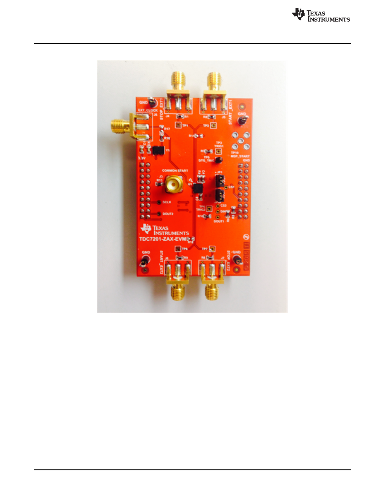
1.2 TDC7201EVM
www.ti.com
Figure 1. TDC7201EVM Evaluation Board
2
TDC7201-ZAX-EVM
Copyright © 2016, Texas Instruments Incorporated
SNAU198A–May 2016–Revised May 2016
Submit Documentation Feedback
Page 3

www.ti.com
2 Equipment List
1. TDC7201EVM
2. TDC720xEVM GUI (http://www.ti.com/tool/tdc7201-zax-evm)
3. MSP430 launchpad (http://www.ti.com/tool/msp-exp430f5529lp)
4. Micro-USB cable
5. Dual function generator (for example: Tektronix AFG3102 1GS/s, 100MHz)
6. PC with Windows XP or Windows 7
7. 4 BNC-to-SMA cables
3 Quick Start
1. Download and Install TDC720xEVM (GUI) Software. See Section 4 for more information.
2. Connect the USB cable from the MSP430 LaunchPad to the PC.
3. Connect the TDC7201EVM to the MSP430 LaunchPad via J1 and J2.
4. Connect START1 and STOP1 pulses to the TDC7201EVM via J5 and J4. See Section 5 for more
information.
5. Launch the GUI. See Section 6 for more information.
6. On the GRAPH tab, press the START GRAPH button.
Equipment List
SNAU198A–May 2016–Revised May 2016
Submit Documentation Feedback
Copyright © 2016, Texas Instruments Incorporated
TDC7201-ZAX-EVM
3
Page 4
Software Installation
4 Software Installation
This section describes software installation, firmware upgrade, and how to update USB Driver.
4.1 Installing the TDC720xEVM GUI
1. Download the TDC720xEVM Software GUI zip file to your desktop. This should be located in
http://www.ti.com/tool/tdc7201-zax-evm.
2. Unzip the file.
3. Run the setup.exe file.
4. Follow the instructions to install the GUI.
5. Once done, you should be able to see the installation in default installation folder; for example,
C:\Program Files (x86)\Texas Instruments\TDC720xEVM.
4.2 MSP430 Firmware Upgrade (This is only needed for a new Launchpad.)
1. Open the TDC720xEVM GUI.
2. Click on the Debug tab.
3. Click on Update Firmware.
4. Click Next to proceed on the first prompt; read and accept the license agreement, and click Next to
continue.
5. Choose Select Firmware, and then click Browse.
a. Go to the folder where you downloaded the TDC720xEVM GUI. The default install folder is
C:\Program Files (x86)\Texas Instruments\TDC720xEVM
b. Find the Firmware folder. It is located within the default installation folder, C:\Program Files
(x86)\Texas Instruments\TDC720xEVM\Firmware
c. Select the TDC720xEVM firmware text file.
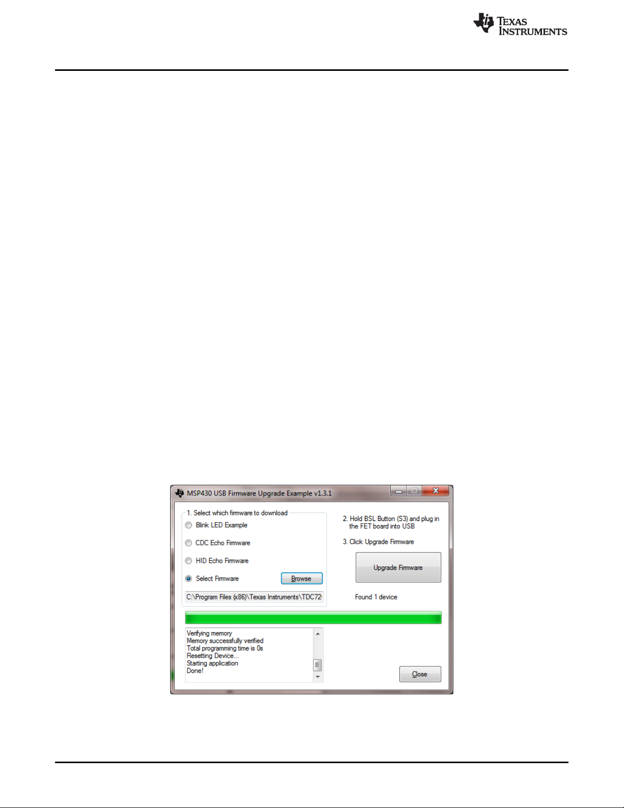
6. On the MSP430 LaunchPad board, press the BSL button (S5) and connect the MSP430 Launch
Pad to your PC using a USB cable. If detected, the text displayed on the Firmware Upgrade tool
changes from No device connected to Found 1 device. See Figure 2.
7. On the MSP430 USB Firmware Upgrade GUI, click Upgrade Firmware.
8. Click Close when done.
www.ti.com
Figure 2. Upgrading MSP430 Firmware
4
TDC7201-ZAX-EVM
Copyright © 2016, Texas Instruments Incorporated
SNAU198A–May 2016–Revised May 2016
Submit Documentation Feedback
Page 5
www.ti.com
4.3 Checking Connection
1. If you haven’t done so, connect the USB cable from the MSP430 Launch Pad to your PC.
2. If you haven’t done so, connect the TDC7201EVM to the MSP430 Launch Pad via J1 and J2 as shown
in Figure 6.
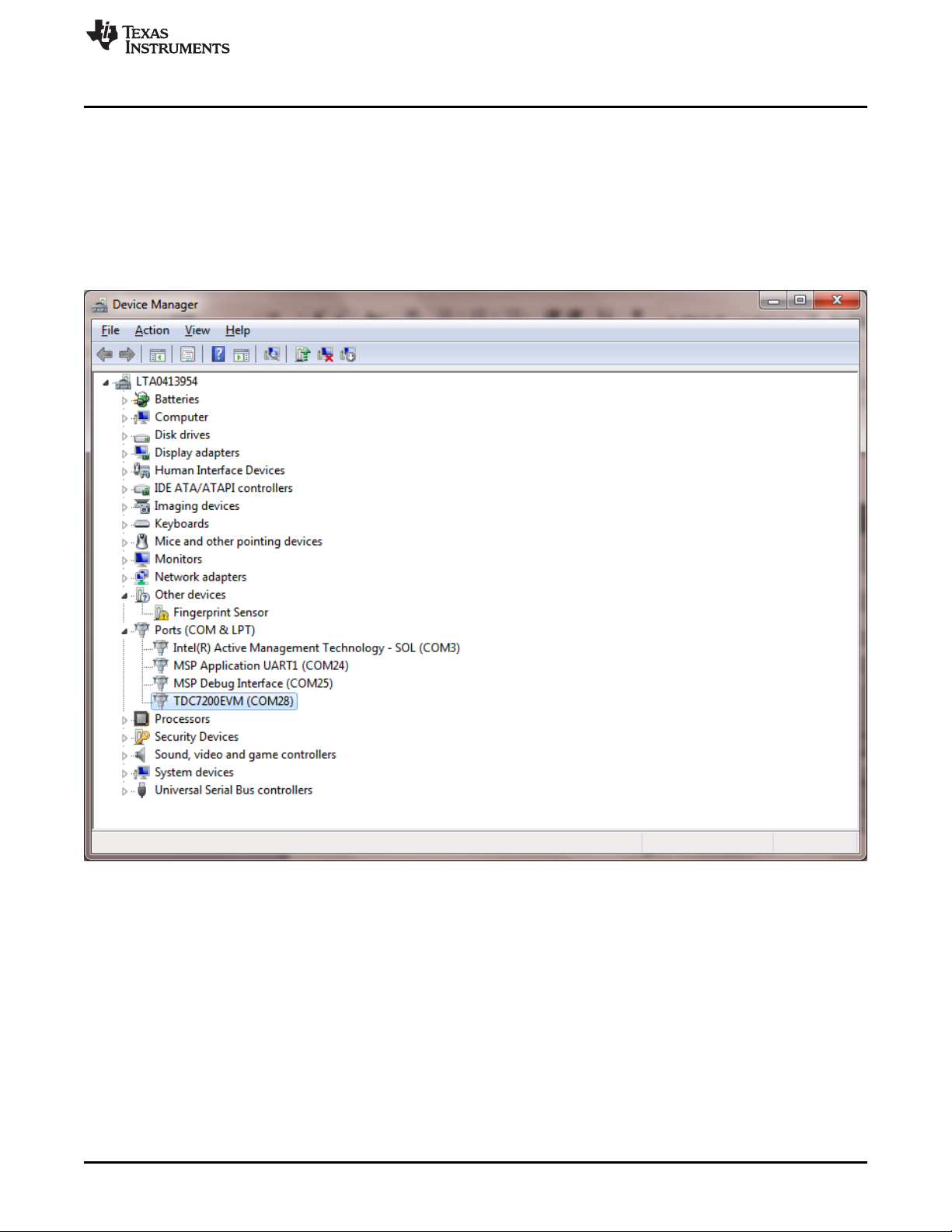
3. Open the computer’s Device Manager . To do this, right-click My Computer, click Properties, and
select Device Manager.
4. Scroll down to Ports (COM & LPT) and check TDC7200EVM (COMx) connection as shown in
Figure 3.
Software Installation
SNAU198A–May 2016–Revised May 2016
Submit Documentation Feedback
Figure 3. Device Manager
Copyright © 2016, Texas Instruments Incorporated
TDC7201-ZAX-EVM
5
Page 6
Software Installation
4.4 Opening the GUI
1. If you haven’t done so, connect the USB cable from the MSP430 Launch Pad to your PC.
2. If you haven’t done so, connect the TDC7201EVM to the MSP430 Launch Pad via J1 and J2 as shown
in Figure 6.
3. Run the TDC720xEVM GUI from the Start Menu. By default, it is located in Programs\Texas
Instruments\TDC720xEVM.
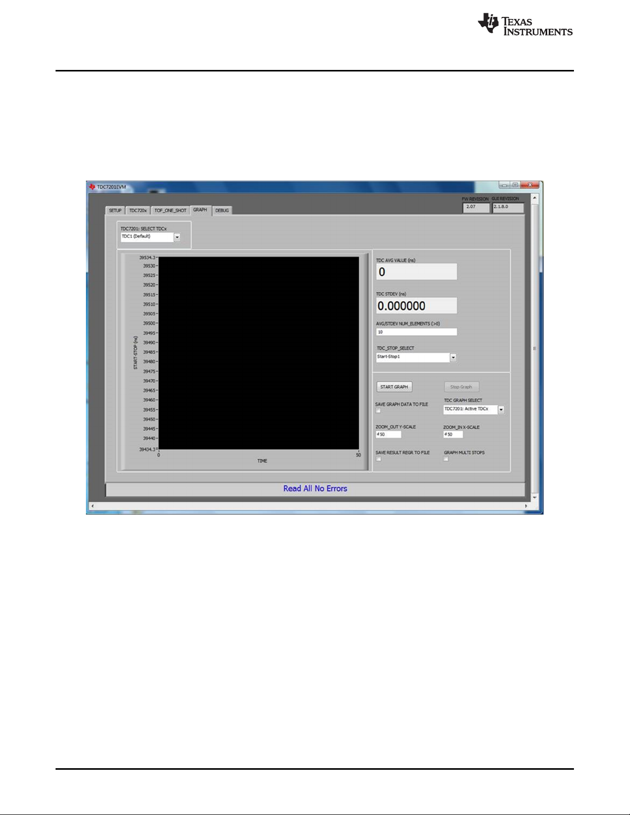
4. GUI should automatically connect and show the screen depicted in Figure 4.
www.ti.com
Figure 4. TDC720xEVM GUI
6
TDC7201-ZAX-EVM
Copyright © 2016, Texas Instruments Incorporated
SNAU198A–May 2016–Revised May 2016
Submit Documentation Feedback
Page 7
www.ti.com
5 Hardware Configuration
This section describes how to properly set up the connections on the EVM
5.1 TDC7201EVM Connections
1. If you haven’t done so, connect the USB cable from the MSP430 Launch Pad to your PC.
2. If you haven't done so, connect the TDC7201EVM to the MSP430 Launch Pad via J1 and J2 as
shown in Figure 6.
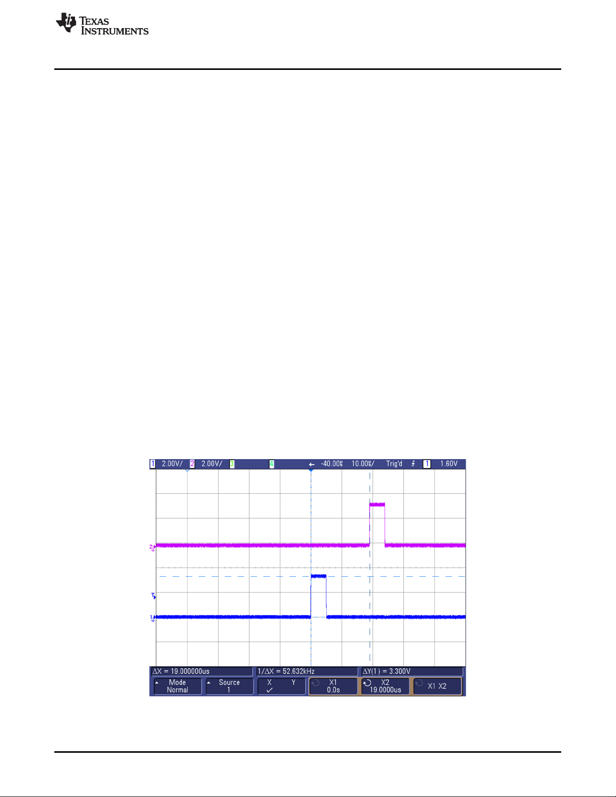
3. Setting the Dual Channel Function Generator:
i. Set channel 1 of the dual function generator to the following (see Figure 5):
i. Pulse 1-Cycle
ii. Burst mode
iii. Freq = 40 kHz
iv. Delay = 0 s
v. Amplitude = 3.3 Vpp
vi. Offset = 1.65 V
vii. Duty = 20%
viii. Burst Trigger Source = External
ii. Set channel 2 of the dual function generator to the following (see Figure 5):
i. Pulse 1-Cycle
ii. Burst mode
iii. Freq = 40 kHz
iv. Delay = 19 µs --> this is the time-of-flight (TOF)
v. Amplitude = 3.3 Vpp
vi. Offset = 1.65 V
vii. Duty = 20%
viii. Burst Trigger Source = External
Hardware Configuration
Figure 5. START and STOP Signals Scope Shot
SNAU198A–May 2016–Revised May 2016
Submit Documentation Feedback
Copyright © 2016, Texas Instruments Incorporated
TDC7201-ZAX-EVM
7
Page 8

Hardware Configuration
4. Connecting the Input Signal:
a. Using a USB-to-SMA cable, connect channel 1 of the dual function generator to TDC7201EVM’s
START1_EXT connector (J5).
b. Using a USB-to-SMA cable, connect channel 2 of the dual function generator to TDC7201EVM’s
STOP1_EXT connector (J4). See Figure 6.
5. Connecting the Trigger Input:
a. Connect DTG_TRIG (TP9) to the TRIGG input of the dual function generator. DTG_TRIG is
generated by the MCU whenever a new measurement is started by the TDC7201. See Figure 6
and Figure 7.
www.ti.com
Figure 6. TDC7201EVM Connection Setup
8
TDC7201-ZAX-EVM
Copyright © 2016, Texas Instruments Incorporated
SNAU198A–May 2016–Revised May 2016
Submit Documentation Feedback
Page 9

www.ti.com
Hardware Configuration
Figure 7. Tektronix AFG3102 Connections
SNAU198A–May 2016–Revised May 2016
Submit Documentation Feedback
Copyright © 2016, Texas Instruments Incorporated
TDC7201-ZAX-EVM
9
Page 10

Hardware Configuration
5.2 Jumpers
The following shows the jumper connection:
1. JP1: Jumper for VCC power
a. Connect Pin 1 to Pin 2 – power VCC via MSP430 (recommended)
b. Open Pin 1 and Pin 2 – no connection to VCC via MSP430; need to apply external power
2. JP2: Jumper for CLOCK source
a. Connect Pin 1 to Pin 2 – power VCC via MSP430 (recommended)
b. Open Pin 1 and Pin 2 – no connection to VCC via MSP430; need to apply external power
6 GUI and Operation
1. If you haven’t done so, open the TDC720xEVM GUI. The EVM GUI software can be run by clicking on
Start, then clicking All Programs, Texas Instruments, and TDC720xEVM and selecting
TDC720xEVM.
2. Click on the TDC720x tab and make sure TDC1 is selected with the register configuration in Figure 8:
www.ti.com
10
TDC7201-ZAX-EVM
Figure 8. Recommended TDC7201:TDC1 Register Configuration
SNAU198A–May 2016–Revised May 2016
Copyright © 2016, Texas Instruments Incorporated
Submit Documentation Feedback
Page 11

www.ti.com
3. Click on the Graph tab, then click on START GRAPH. You should be able to read 19 µs (assuming
4. Calculating Time-of-Flight:
GUI and Operation
you follow the instructions as specified in Section 5.1).
Figure 9. Graphing
a. In the GUI, click on the TOF_ONE_SHOT tab.
b. You should be able to see similar measurement results register values as shown in Figure 10
(assuming you follow the instructions as specified in Section 5.1).
c. To calculate the time-of-flight, use the Measurement Mode 2 Time-of-Flight calculation as shown in
Equation 1. For more information, refer to the TDC7201 data sheet (SNAS686).
d. Use the values reported in the Measurement Result Registers (Figure 10) to validate the time-of-
flight as approximately 19 µs (assuming you follow the instructions as specified in Section 5.1).
SNAU198A–May 2016–Revised May 2016
Submit Documentation Feedback
Figure 10. Measurement Results
Copyright © 2016, Texas Instruments Incorporated
TDC7201-ZAX-EVM
11
Page 12

11
CALIBRATION2 CALIBRATION1 (4354 2179)
calCount 2175
(CALIBRATION2_PERIODS) 1 (2) 1
(CLOCKperiod) (1/ 8MHz)
normLSB 57.4ps
(calCount) 2175
TOF1 normLSB(TIME1 TIME2) (CLOCK_COUNT1)(CLOCKperiod)
TOF1 (5.74 10
)(1688 1667) (152)(1/ 8MHz)
TOF1 19.001us
n n n 1
n n 1 n
TOF (TIME1)(normLSB) offset (CLOCK _COUNT )(CLOCKperiod) (TIME )(normLSB) offset
TOF normLSB(TIME1 TIME ) (CLOCK _COUNT )(CLOCKperiod)
(CLOCKperiod)
normLSB
(calCount)
CALIBRATION2 CA
calCount
ª º ª º
¬ ¼ ¬ ¼
LIBRATION1
(CALIBRATION2_PERIODS) 1
GUI and Operation
where
www.ti.com
• TOFn [second] = time-of-flight measurement from the START to the nth STOP
• normLSB [sec] = normalized LSB value from calibration
• TIME1 = time 1 measurement given by the TDC7201 register address 0x10
• TIME
and 0x1A
• CLOCK_COUNTn = nth clock count values in register addresses 0x11, 0x13, 0x15, 0x17, and 0x19
• CLOCKperiod [sec] = external CLOCK period
• offset [sec]= constant measurement offset
• CALIBRATION1 [count] = TDC count for first calibration cycle, located in register address 0x1B
• CALIBRATION2 [count] = TDC count for second calibration cycle, located in register address 0x1C
• CALIBRATION2_PERIODS = calibration count bits, located in register address 0x01 (1)
= (n+1) time measurement given by the TDC7201 register addresses 0x12, 0x14, 0x16, 0x18,
n+1
5. START_EXT2/STOP_EXT2 Testing
a. Modification to Input Signal Connections:
1. Disconnect USB-to-SMA cable connection to START_EXT1 (J5). Instead, reconnect channel 1
of the dual function generator to TDC7201EVM’s START_EXT2 connector (J8).
2. Disconnect USB-to-SMA cable connection to STOP_EXT1 (J4). Instead, reconnect channel 2
of the dual function generator to TDC7201EVM’s STOP_EXT2 connector (J7). See Figure 4.
b. Now repeat steps 1 through 4 from Section 6 with the following modification to step 2: Click on the
TDC720x tab and make sure the TDC7201: Select TDCx field is as shown in Figure 11.
12
TDC7201-ZAX-EVM
SNAU198A–May 2016–Revised May 2016
Copyright © 2016, Texas Instruments Incorporated
(2)
Submit Documentation Feedback
Page 13

www.ti.com
GUI and Operation
Figure 11. Recommended TDC7201:TDC2 Register Configuration
SNAU198A–May 2016–Revised May 2016
Submit Documentation Feedback
Copyright © 2016, Texas Instruments Incorporated
TDC7201-ZAX-EVM
13
Page 14

Board Layout
7 Board Layout
NOTE: The board layout is not to scale. Figure 12 thru Figure 15 are intended to show how the board is
laid out; it is not intended to be used for manufacturing.
www.ti.com
14
TDC7201-ZAX-EVM
Figure 12. TDC7201EVM Top Layer
Copyright © 2016, Texas Instruments Incorporated
SNAU198A–May 2016–Revised May 2016
Submit Documentation Feedback
Page 15

www.ti.com
Board Layout
SNAU198A–May 2016–Revised May 2016
Submit Documentation Feedback
Figure 13. TDC7201EVM Bottom Layer
Copyright © 2016, Texas Instruments Incorporated
TDC7201-ZAX-EVM
15
Page 16

Board Layout
www.ti.com
16
TDC7201-ZAX-EVM
Figure 14. TDC7201EVM Ground Plane
Copyright © 2016, Texas Instruments Incorporated
SNAU198A–May 2016–Revised May 2016
Submit Documentation Feedback
Page 17

www.ti.com
TDC7201EVM Schematic
8 TDC7201EVM Schematic
The TDC7201EVM Schematic is shown in Figure 16.
SNAU198A–May 2016–Revised May 2016
Submit Documentation Feedback
Figure 15. TDC7201EVM Power Plane
Copyright © 2016, Texas Instruments Incorporated
TDC7201-ZAX-EVM
17
Page 18

START_EXT1
STOP_EXT1
GND
GND
TRIG1
OSC_ENABLE
VCC
GND
GND
VCC
SH-JP1
GND GND
INT1
DOUT1
DIN
CS1
SCLK
GND
TRIG1
CS1
ENABLE1
1
TP1
1
TP2
1
234
5
J6
142-0701-801
1
234
5
J4
142-0701-801
1
234
5
J5
142-0701-801
OSC_ENABLE
10µF
C1
1µF
C4
GND
0.01µF
C5
8MHz
VDD
4
OE/STANDBY
1
GND
2
OUT
3
Y1
VCC
GND
GND
GND
GND
1
TP7
1
TP8
1
234
5
J7
142-0701-801
1
234
5
J8
142-0701-801
0.1µFC60.01µF
C7
1µF
C8
1
TP6
VCC
VCC
CS2
INT2
START_EXT2
STOP_EXT2
INT2
CS2
TRIG2
1
TP9
DTG_TRIG
MSP_START
1
234
5
J3
0
R11
0
R12
GND
SH-JP3
DTG_TRIG
MSP_START
GND
1
234
5
TP10
GND
1
3
56
4
2
7
910
8
12 11
14 13
16 15
18 17
20 19
J2
PPPC102LFBN-RC
1
2
JP1
ICC
1
2
JP3
ICC
TP4 TP5
1
3
56
4
2
7
910
8
12 11
14 13
16 15
18 17
20 19
J1
PPPC102LFBN-RC
GND
INT1
VCC
10.0k
R5
0
R10
10.0k
R6
49.9
R1
49.9
R2
49.9
R8
49.9
R9
49.9
R13
1
TP3
0
R3
TRIG2
VREG1
VREG2
VDD2VDD1
VDD1
VDD2
ENABLE1
CLOCK_TDC_CAL
SCLK
DIN
START_EXT1
STOP_EXT1
START_EXT2
STOP_EXT2
0.1µFC20.01µF
C3
GND
0
R7
SCLK
OSC_OUT
CLOCK_TDC_CAL
0
R18
EXT_CLOCK
0
R17
0
R16
0
R4
0
R15
0
R14
DIN
DOUT2
DOUT1
DOUT2
NOTE: 1.Add via on each SPI pins and label
2. Take all SPI bus and digital pins to Bottom Layer
3. START1, START2,STOP1, STOP2 must be symmetic and equal
from device's pin
4. Add J3 vertical narrowSMA between START1 and START2
5. Distance J3 must be the samefor START1 andSTART2
GND
TP13
GND
TP14
CLOCK
C1
CSB1
B5
CSB2
E5
DIN
D5
DOUT1
C5
DOUT2
E3
ENABLE
A3
GND1
B2
GND2
E2
INTB1
B3
INTB2
D3
SCLK
A5
START1
A1
START2
D1
STOP1
B1
STOP2
E1
TRIGG1
A2
TRIGG2
D2
VDD1
B4
VDD2
C4
VREG1
A4
VREG2
E4
NC
C2
NC
C3
NC
D4
U1
TDC7201ZAXR
GND
GND
SV601269
A
PCB Number:
PCB Rev:
Assembly Note
ZZ1
Short SH-JP1 and SH-JP3 on JP1 pin 1-2 and JP3 pin 1-2
FID2FID1 FID3
LOGO
PCB
FCC disclaimer
FID5FID4 FID6
LOGO
PCB
Logo1
LOGO
PCB
Logo2
Copyright © 2016, Texas Instruments Incorporated
TDC7201EVM Schematic
www.ti.com
18
TDC7201-ZAX-EVM
Figure 16. TDC7201EVM Schematic
Copyright © 2016, Texas Instruments Incorporated
SNAU198A–May 2016–Revised May 2016
Submit Documentation Feedback
Page 19

www.ti.com
9 Bill of Materials
Bill of Materials
Table 1. TDC7201EVM Bill of Materials
Designator Qty Value Description Package
C1 1 10uF CAP, CERM, 10 µF, 6.3 V, +/- 20%,
C2, C6 2 0.1uF CAP, CERM, 0.1 µF, 16 V, +/- 5%,
C3, C5, C7 3 0.01uF CAP, CERM, 0.01 µF, 100 V, +/- 5%,
C4, C8 2 1uF CAP, CERM, 1 µF, 16 V, +/- 10%,
J1, J2 2 Receptacle, 100mil, 10x2, Gold, TH 10x2 Receptacle PPPC102LFBN-RCSullins
J3 1 Connector, TH, SMA SMA 142-0701-201 Emerson
J4, J5, J6, J7, J8 5 Connector, End launch SMA, 50
JP1, JP3 2 Header, 100mil, 2x1, Gold, TH 2x1 Header TSW-102-07-G-SSamtec
R1, R2, R8, R9,
R13
R3, R4, R10,
R16, R18
R5, R6 2 10.0k RES, 10.0 k, 1%, 0.1 W, 0603 0603 CRCW060310K
SH-JP1, SH-JP3 2 1x2 Shunt, 100mil, Gold plated, Black Shunt 969102-0000-DA 3M
TP4, TP5, TP13,
TP14
TP9 1 Header, 100mil, 1pos, Gold, TH Testpoint TSW-101-07-G-SSamtec
5 49.9 RES, 49.9, 1%, 0.1 W, 0603 0603 CRCW060349R
5 0 RES, 0, 5%, 0.1 W, 0603 0603 CRCW06030000
4 Black Test Point, Multipurpose, Black, TH Black
X5R, 0603
X7R, 0603
X7R, 0603
X7R, 0603
ohm, SMT
Reference
0603 C0603C106M9P
0603 0603YC104JAT2AAVX
0603 06031C103JAT2AAVX
0603 EMK107B7105K
End Launch
SMA
Multipurpose
Testpoint
Part Number Manufacturer
Kemet
ACTU
Taiyo Yuden
A-T
Connector
Solutions
Network Power
142-0701-801 Johnson
Vishay-Dale
9FKEA
Vishay-Dale
Z0EA
Vishay-Dale
0FKEA
5011 Keystone
U1 1 Time-to-Digital Converter for Time-
Y1 1 OSC, 8MHz, 15pF, SMD OSC,
FID1, FID2,
FID3, FID4,
FID5, FID6
R7, R11, R12,
R14, R15, R17
TP1, TP2, TP3,
TP6, TP7, TP8
TP10 0 Connector, TH, SMA SMA 142-0701-201 Emerson
SNAU198A–May 2016–Revised May 2016
Submit Documentation Feedback
0 Fiducial mark. There is nothing to
0 0 RES, 0, 5%, 0.1 W, 0603 0603 CRCW06030000
0 Header, 100mil, 1pos, Gold, TH Testpoint TSW-101-07-G-SSamtec
of-FlightApplications in LIDAR,
ZAX0025A TDC7201ZAXR Texas
Magnetostrictive andFlowMeters,
ZAX0025A
3.2x.85x5mm
N/A N/A N/A
buy or mount.
Copyright © 2016, Texas Instruments Incorporated
ASFLMB-
8.000MHZ-LY-T
Z0EA
TDC7201-ZAX-EVM
Instruments
Abracon
Corporation
Vishay-Dale
Network Power
19
Page 20

Revision History
www.ti.com
Revision History
NOTE: Page numbers for previous revisions may differ from page numbers in the current version.
Changes from Original (May 2016) to A Revision ........................................................................................................... Page
• Changed link to Gui....................................................................................................................... 3
• Changed link to Gui....................................................................................................................... 4
20
Revision History
Copyright © 2016, Texas Instruments Incorporated
SNAU198A–May 2016–Revised May 2016
Submit Documentation Feedback
Page 21

IMPORTANT NOTICE FOR TI DESIGN INFORMATION AND RESOURCES
Texas Instruments Incorporated (‘TI”) technical, application or other design advice, services or information, including, but not limited to,
reference designs and materials relating to evaluation modules, (collectively, “TI Resources”) are intended to assist designers who are
developing applications that incorporate TI products; by downloading, accessing or using any particular TI Resource in any way, you
(individually or, if you are acting on behalf of a company, your company) agree to use it solely for this purpose and subject to the terms of
this Notice.
TI’s provision of TI Resources does not expand or otherwise alter TI’s applicable published warranties or warranty disclaimers for TI
products, and no additional obligations or liabilities arise from TI providing such TI Resources. TI reserves the right to make corrections,
enhancements, improvements and other changes to its TI Resources.
You understand and agree that you remain responsible for using your independent analysis, evaluation and judgment in designing your
applications and that you have full and exclusive responsibility to assure the safety of your applications and compliance of your applications
(and of all TI products used in or for your applications) with all applicable regulations, laws and other applicable requirements. You
represent that, with respect to your applications, you have all the necessary expertise to create and implement safeguards that (1)
anticipate dangerous consequences of failures, (2) monitor failures and their consequences, and (3) lessen the likelihood of failures that
might cause harm and take appropriate actions. You agree that prior to using or distributing any applications that include TI products, you
will thoroughly test such applications and the functionality of such TI products as used in such applications. TI has not conducted any
testing other than that specifically described in the published documentation for a particular TI Resource.
You are authorized to use, copy and modify any individual TI Resource only in connection with the development of applications that include
the TI product(s) identified in such TI Resource. NO OTHER LICENSE, EXPRESS OR IMPLIED, BY ESTOPPEL OR OTHERWISE TO
ANY OTHER TI INTELLECTUAL PROPERTY RIGHT, AND NO LICENSE TO ANY TECHNOLOGY OR INTELLECTUAL PROPERTY
RIGHT OF TI OR ANY THIRD PARTY IS GRANTED HEREIN, including but not limited to any patent right, copyright, mask work right, or
other intellectual property right relating to any combination, machine, or process in which TI products or services are used. Information
regarding or referencing third-party products or services does not constitute a license to use such products or services, or a warranty or
endorsement thereof. Use of TI Resources may require a license from a third party under the patents or other intellectual property of the
third party, or a license from TI under the patents or other intellectual property of TI.
TI RESOURCES ARE PROVIDED “AS IS” AND WITH ALL FAULTS. TI DISCLAIMS ALL OTHER WARRANTIES OR
REPRESENTATIONS, EXPRESS OR IMPLIED, REGARDING TI RESOURCES OR USE THEREOF, INCLUDING BUT NOT LIMITED TO
ACCURACY OR COMPLETENESS, TITLE, ANY EPIDEMIC FAILURE WARRANTY AND ANY IMPLIED WARRANTIES OF
MERCHANTABILITY, FITNESS FOR A PARTICULAR PURPOSE, AND NON-INFRINGEMENT OF ANY THIRD PARTY INTELLECTUAL
PROPERTY RIGHTS.
TI SHALL NOT BE LIABLE FOR AND SHALL NOT DEFEND OR INDEMNIFY YOU AGAINST ANY CLAIM, INCLUDING BUT NOT
LIMITED TO ANY INFRINGEMENT CLAIM THAT RELATES TO OR IS BASED ON ANY COMBINATION OF PRODUCTS EVEN IF
DESCRIBED IN TI RESOURCES OR OTHERWISE. IN NO EVENT SHALL TI BE LIABLE FOR ANY ACTUAL, DIRECT, SPECIAL,
COLLATERAL, INDIRECT, PUNITIVE, INCIDENTAL, CONSEQUENTIAL OR EXEMPLARY DAMAGES IN CONNECTION WITH OR
ARISING OUT OF TI RESOURCES OR USE THEREOF, AND REGARDLESS OF WHETHER TI HAS BEEN ADVISED OF THE
POSSIBILITY OF SUCH DAMAGES.
You agree to fully indemnify TI and its representatives against any damages, costs, losses, and/or liabilities arising out of your noncompliance with the terms and provisions of this Notice.
This Notice applies to TI Resources. Additional terms apply to the use and purchase of certain types of materials, TI products and services.
These include; without limitation, TI’s standard terms for semiconductor products http://www.ti.com/sc/docs/stdterms.htm), evaluation
modules, and samples (http://www.ti.com/sc/docs/sampterms.htm).
Mailing Address: Texas Instruments, Post Office Box 655303, Dallas, Texas 75265
Copyright © 2018, Texas Instruments Incorporated
Page 22

Mouser Electronics
Authorized Distributor
Click to View Pricing, Inventory, Delivery & Lifecycle Information:
Texas Instruments:
TDC7201-ZAX-EVM
 Loading...