

Texas Instruments SN74ACT7804-20DL, SN74ACT7804-20DLR, SN74ACT7804-25DL, SN74ACT7804-25DLR, SN74ACT7804-40DL Datasheet
...
SN74ACT7804
512 × 18 STROBED FIRST-IN, FIRST-OUT MEMORY
SCAS204C – APRIL 1992 – REVISED APRIL 1998
D
Member of the Texas Instruments
Widebus Family
D
Load Clock and Unload Clock Can Be
Asynchronous or Coincident
D
512 Words by 18 Bits
D
Low-Power Advanced CMOS Technology
D
Full, Empty, and Half-Full Flags
D
Programmable Almost-Full/Almost-Empty
Flag
D
Fast Access Times of 15 ns With a 50-pF
Load and All Data Outputs Switching
Simultaneously
D
Data Rates up to 50 MHz
D
3-State Outputs
D
Pin-to-Pin Compatible With SN74ACT7806
and SN74ACT7814
D
Packaged in Shrink Small-Outline 300-mil
Package Using 25-mil Center-to-Center
Spacing
description
A FIFO memory is a storage device that allows
data to be written into and read from its array at
independent data rates. The SN74ACT7804 is a
512-word by 18-bit FIFO for high speed and fast
access times. It processes data at rates up to
50 MHz and access times of 15 ns in a bit-parallel
format.
Data is written into memory on a low-to-high
transition at the load-clock (LDCK) input and is
read out on a low-to-high transition at the
unload-clock (UNCK) input. The memory is full
when the number of words clocked in exceeds the
number of words clocked out by 512. When the
memory is full, LDCK signals have no effect on the
data residing in memory. When the memory is
empty, UNCK signals have no effect.
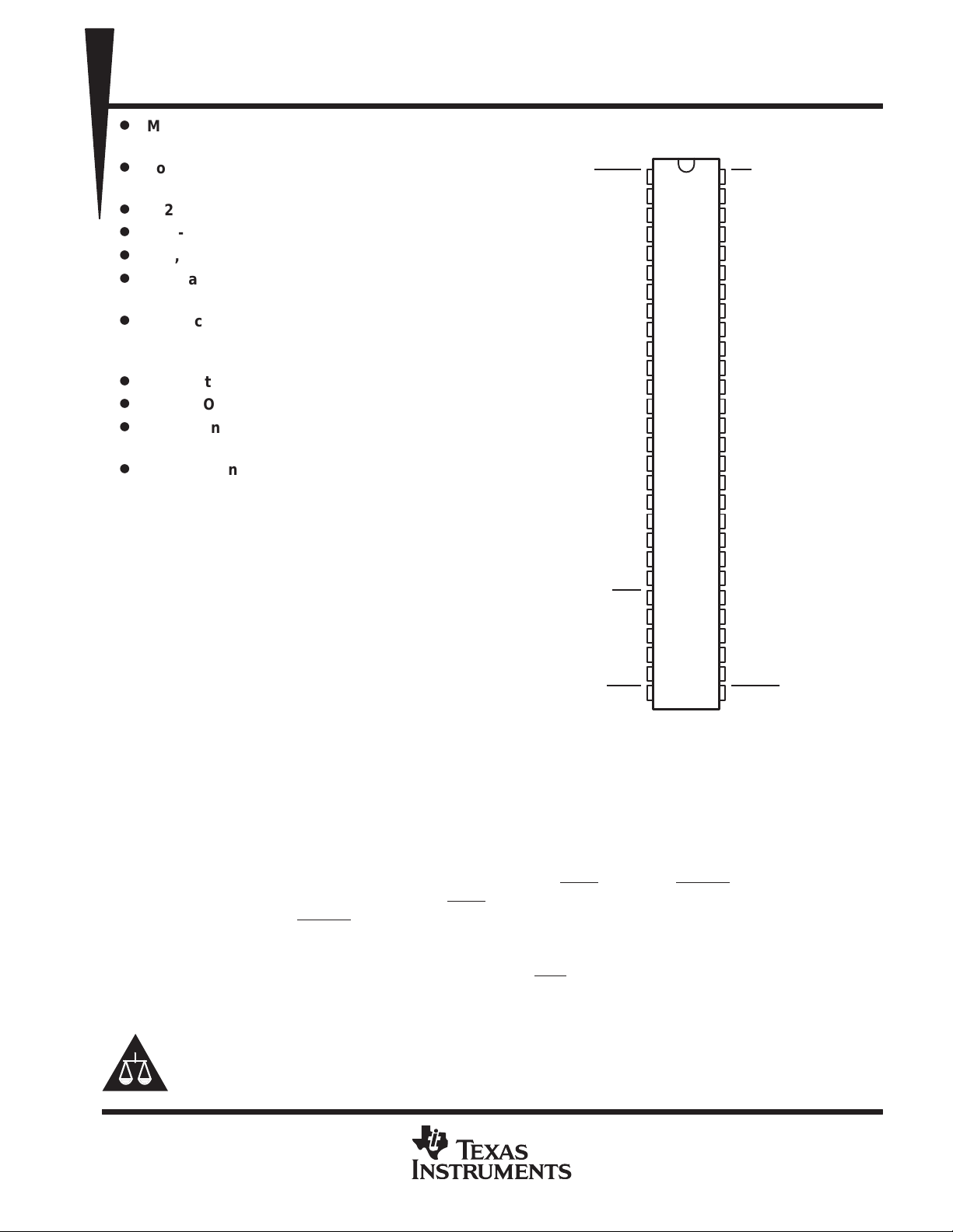
DL PACKAGE
(TOP VIEW)
RESET
GND
AF/AE
LDCK
FULL
NC – No internal connection
D17
D16
D15
D14
D13
D12
D1 1
D10
V
CC
D9
D8
D7
D6
D5
D4
D3
D2
D1
D0
HF
PEN
NC
NC
1
2
3
4
5
6
7
8
9
10
11
12
13
14
15
16
17
18
19
20
21
22
23
24
25
26
27
28
56
55
54
53
52
51
50
49
48
47
46
45
44
43
42
41
40
39
38
37
36
35
34
33
32
31
30
29
OE
Q17
Q16
Q15
GND
Q14
V
Q13
Q12
Q11
Q10
Q9
GND
Q8
Q7
Q6
Q5
V
Q4
Q3
Q2
GND
Q1
Q0
UNCK
NC
NC
EMPTY
CC
CC
Status of the FIFO memory is monitored by the full (FULL
almost-full/almost-empty (AF/AE) flags. The FULL
memory is not full. The EMPTY
output is low when the memory is empty and high when it is not empty . The HF
output is low when the memory is full and high when the
), empty (EMPTY), half-full (HF), and
output is high when the FIFO contains 256 or more words. The AF/AE status flag is a programmable flag. The
first one or two low-to-high transitions of LDCK after reset are used to program the almost-empty offset value
(X) and the almost-full offset value (Y) if program enable (PEN
) is low. The AF/AE flag is high when the FIFO
contains X or fewer words or (512 – Y) or more words. The AF/AE flag is low when the FIFO contains between
(X + 1) and (511 – Y) words.
Please be aware that an important notice concerning availability, standard warranty, and use in critical applications of
Texas Instruments semiconductor products and disclaimers thereto appears at the end of this data sheet.
Widebus is a trademark of Texas Instruments Incorporated.
PRODUCTION DATA information is current as of publication date.
Products conform to specifications per the terms of Texas Instruments
standard warranty. Production processing does not necessarily include
testing of all parameters.
POST OFFICE BOX 655303 • DALLAS, TEXAS 75265
Copyright 1998, Texas Instruments Incorporated
1
SN74ACT7804
512 × 18 STROBED FIRST-IN, FIRST-OUT MEMORY
SCAS204C – APRIL 1992 – REVISED APRIL 1998
description (continued)
A low level on the reset (RESET) input resets the internal stack pointers and sets FULL high, AF/AE high, HF
low, and EMPTY
power up.
low. The Q outputs are not reset to any specific logic level. The FIFO must be reset upon
The first word loaded into empty memory causes EMPTY
to go high and the data to appear on the Q outputs.
It is important to note that the first word does not have to be unloaded. The data outputs are noninverting with
respect to the data inputs and are in the high-impedance state when the output-enable (OE
) input is high.
The SN74ACT7804 is characterized for operation from 0°C to 70°C.
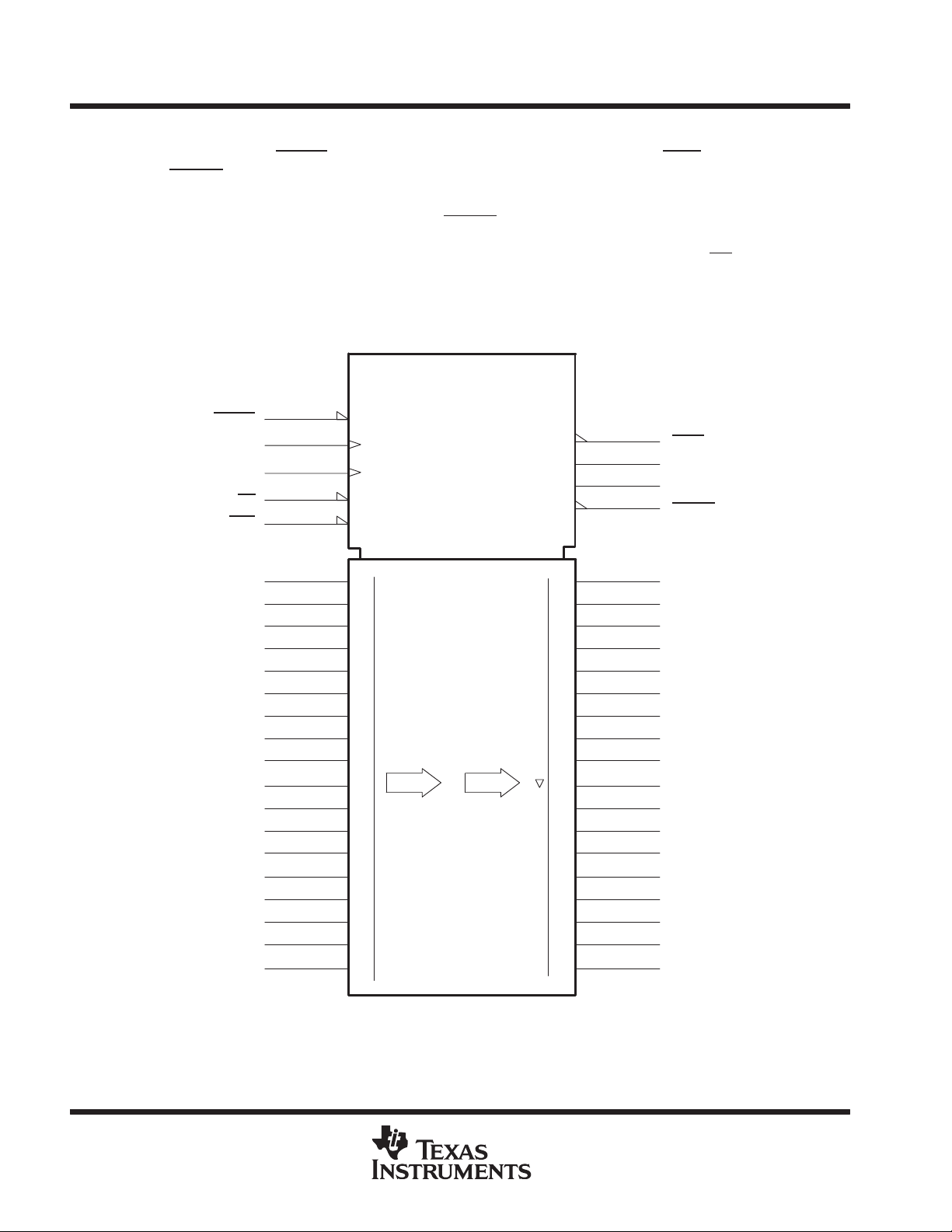
logic symbol
†
Φ
FIFO 512 × 18
SN74ACT7804
ALMOST FULL/EMPTY
Data
Data
FULL
HALF-FULL
EMPTY
1
17
28
FULL
22
HF
24
AF/AE
29
EMPTY
33
0
34
36
37
38
40
41
42
43
45
46
47
48
49
51
53
54
55
Q0
Q1
Q2
Q3
Q4
Q5
Q6
Q7
Q8
Q9
Q10
Q11
Q12
Q13
Q14
Q15
Q16
Q17
RESET
LDCK
UNCK
OE
PEN
D0
D1
D2
D3
D4
D5
D6
D7
D8
D9
D10
D11
D12
D13
D14
D15
D16
D17
1
25
32
56
23
21
20
19
18
17
16
15
14
12
11
9
8
7
6
5
4
3
2
RESET
LDCK
UNCK
EN1
PROGRAM ENABLE
0
17
†
This symbol is in accordance with ANSI/IEEE Std 91-1984 and IEC Publication 617-12.
2
POST OFFICE BOX 655303 • DALLAS, TEXAS 75265
I/O
DESCRIPTION
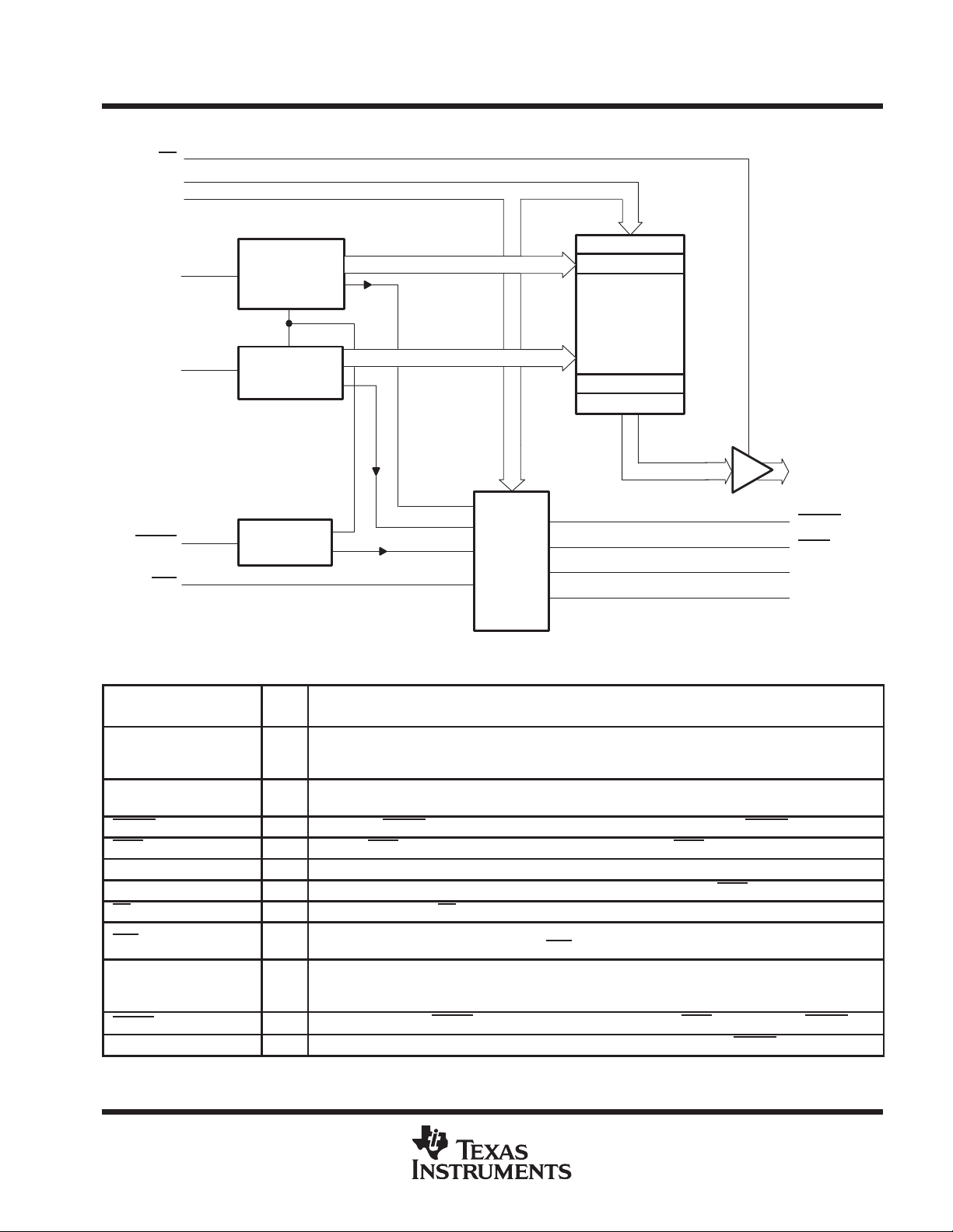
functional block diagram
OE
D0–D17
UNCK
Read
Pointer
SN74ACT7804
512 × 18 STROBED FIRST-IN, FIRST-OUT MEMORY
SCAS204C – APRIL 1992 – REVISED APRIL 1998
Location 1
Location 2
512 × 18 SRAM
LDCK
RESET
PEN
Write
Pointer
Reset
Logic
Status-
Flag
Logic
Location 511
Location 512
Q0–Q17
EMPTY
FULL
HF
AF/AE
Terminal Functions
TERMINAL
NAME NO.
Almost-full/almost-empty flag. Depth-offset values can be programmed for AF/AE, or the default value
AF/AE 24 O
D0–D17
EMPTY 29 O Empty flag. EMPTY is low when the FIFO is empty. A FIFO reset also causes EMPTY to go low.
FULL 28 O Full flag. FULL is low when the FIFO is full. A FIFO reset causes FULL to go high.
HF 22 O Half-full flag. HF is high when the FIFO memory contains 256 or more words. HF is low after reset.
LDCK 25 I Load clock. Data is written to the FIFO on the rising edge of LDCK when FULL is high.
OE 56 I Output enable. When OE is high, the data outputs are in the high-impedance state.
PEN
Q0–Q17
RESET
UNCK 32 I Unload clock. Data is read from the FIFO on the rising edge of UNCK when EMPTY is high.
2–9, 11–12,
14–21
23 I
33–34, 36–38,
40–43, 45–49,
51, 53–55
1 I Reset. A low level on RESET resets the FIFO and drives AF/AE and FULL high and HF and EMPTY low.
of 64 can be used for both the almost-empty offset (X) and the almost-full offset (Y). AF/AE is high when
memory contains X or fewer words or (512 – Y) or more words. AF/AE is high after reset.
I 18-bit data input port
Program enable. After reset and before the first word is written to the FIFO, the binary value on D0–D7
is latched as an AF/AE offset value when PEN
O 18-bit data output port
is low and LDCK is high.
POST OFFICE BOX 655303 • DALLAS, TEXAS 75265
3
SN74ACT7804
512 × 18 STROBED FIRST-IN, FIRST-OUT MEMORY
SCAS204C – APRIL 1992 – REVISED APRIL 1998
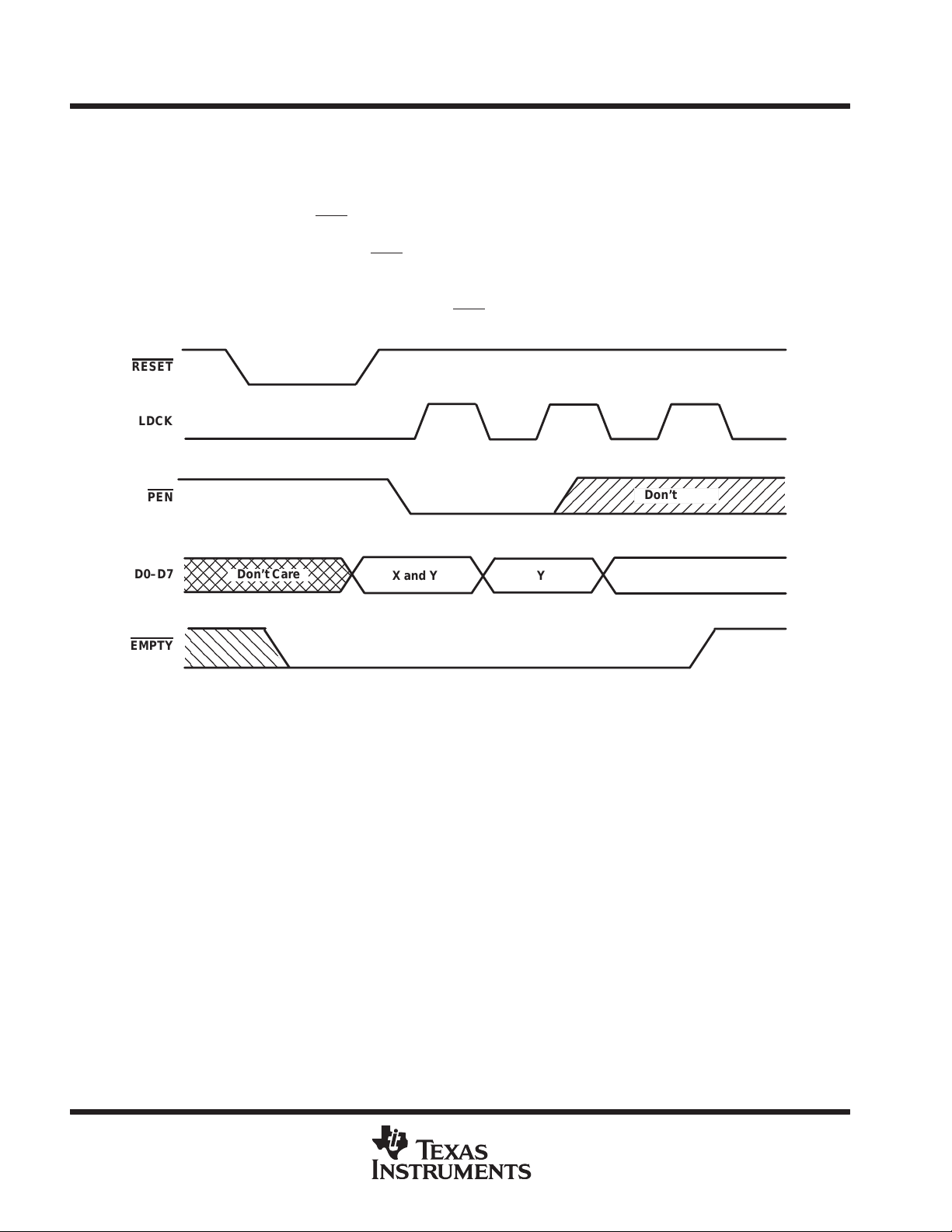
offset values for AF/AE
The AF/AE flag has two programmable limits: the almost-empty offset value (X) and the almost-full offset value
(Y). They can be programmed after the FIFO is reset and before the first word is written to memory . The AF/AE
flag is high when the FIFO contains X or fewer words or (512 – Y) or more words.
To program the offset values, PEN
can be brought low after reset only when LDCK is low. On the following
low-to-high transition of LDCK, the binary value on D0–D7 is stored as the almost-empty offset value (X) and
the almost-full offset value (Y). Holding PEN
low for another low-to-high transition of LDCK reprograms Y to the
binary value on D0–D7 at the time of the second LDCK low-to-high transition. Writes to the FIFO memory are
disabled while the offsets are programmed. A maximum value of 255 can be programmed for either X or Y (see
Figure 1). To use the default values of X = Y = 64, PEN
RESET
LDCK
PEN
D0–D7
EMPTY
Don’t Care
X and Y Y
must be held high.
Don’t Care
Figure 1. Programming X and Y Separately
4
POST OFFICE BOX 655303 • DALLAS, TEXAS 75265
 Loading...