

Page 1
Texas Instruments Home Computer
•
diJ
Disk
Memory
Model No.
0
0
0
0
h.".
h~8l'''tJ'''IN''",
........
0
0 0
0 0
0
0
0
PH
0
0
0
0
P1250
0
0
0
0
0
0
0
0
Drive
1039353·'
Page 2
FEDERAL COMMUNICATIONS COMMISSION REQUIREMENTS
CONCERNING RADIO FREQUENCY INTERFERENCE
The
Texas
frequency
provided
television
This
eqUipment
compullng
Rules.
television
Interference
If
this
delermlne
or
moreofthe
If
these
experienced
Communications
Resolve Radlo·TV
Please
Instruments
(RF)
energy.Ifnot
by
Texas
Instruments),
reception.
has
deviceInaccordance
These
rules
are
Interference
will
not
equipment
by
does
turntng
followtng
•
Reorient
teleVision
Change
•
televlston
•
Plug
the
the
equipment
measures
do
radio/television
Commission
Interference
The
US
Washington,
specify
Stock
Home
Installed
been
type·
designed
In a
residential
occur
cause
the
equipment
In a
Interferencetoradioortelevision
measures:
the
receiving
that
Is "receiVing"
the
positionofthe
eqUipment
computer
not
eliminate
tpchnl"lan
Government
D.
C.
Number
004·000-00345-4
Computer
and
this
eqUipment
tested
with
to
provide
and
the
Installation.
particular
off
antenna
thatIsreceiving
Into a
receiving
the
Interference.
has
prepared
Problems."
Printing
20402
and
peripherals
used
properly
may
foundtocomply
generate
(as
cause
outlined
Interference
with
the
specificationsInSubparlJof
reasonable
protection
However,
thereIsno
Installallon.
reception
and
on),
trytocorrect
(that
the
Interference).
computer
Is,
with
the
the
antenna
respecttothe
Interference.
different
Interference
for
addillonal
a helpful booklet,
This
wall
outlet
are
please
suggestions,
booklet Is
so
on
different
consult
"How
available
that
Office
when
ordering
copies.
against
and
use
radio
In
the
to radIo
limits
for a
Part
radio
guarantee
(which
Interference
for
the
radio
radio
the
computer
branch
your
dealer
Also.
the
Federal
to Identify
from
tnstructlons
and
Class
B
15ofFCC
and
that
you
can
by
one
or
or
and
circuit".
or
an
and
WARNING: ThiS
computing
(computer
ClassBlimits
peripherals
device,
Input/output
may
Is likely to
eqUipment
pursuant
bc
attached
has
to
devtces.
been
Subpart
terminals.
to
this
certified to
J of
computer,
resultInInterferencetoradio
comply
Part
15ofFCC Rules.
printers,
Operation
with
the
etc.) certified to
with
non.certlfied
and
TV
reception.
limits
Only
comply
for a
Class
peripherals
with
B
the
Page 3
Texas Instruments Home Computer
Disk
• 'tc"
...
r.....
TItUAfr
Memory
Model No. PHP1250
0
0
0
0
0
0
0
0
0
...
,..
0
0
0
0
0
0
0
0
0
0
0 0
Drive
0
0
0
0
0
0
,
,
IMPORTANT
Record
Memory
space
by
thl5
PHP1250
Model No. Serle1No.
the
serial
Drive
below.
the
words
Infonnatlon
number
and
the
The
serial
"SERIAL
In
any
from
purchase
number
NO
....
the
Disk
dateInthe
is
identified
Always
correspondence.
reference
Copyright~IVB2,
Tex
••
Instrumant,
Incorporated
Page 4
INTRODUCTION
The
Texas
Instruments
device. Utilizing a
writetoany
constant
magnetic
This
manual
Memory Drive.
disk
system.
positionorfile
speed
and.
read/write
contains
For
please
Drive Controller.
Disk
51,4
Inch
diskette".
on
under
the
headatthe
only
the
instructions
refertothe
Memory
Drive Is a
the
the
diskette.
directionofthe
desired
set-up.
position
service.
regarding
Disk
Memory
disk
The
setup.
high-speed.
drive
can
disk
TI
Disk Drive
on
the
and
warranty
test.
System
high-volume
rapidly
drive
spins
Controller-.
diskette.
Information
and
operationofthe
manual
locate.
the
disketteata
included
memory
read
places
for
complete
with
from.
the
the
and
the
Disk
Disk
Depending
setting
up
Peripheral
three
external
on
the
typeofdisk
the
system.
Expansion
drives
YOII
"an
System
connected
drive
have
and
to
you
are
one
internal
uptotwo
the
system.
using.
disk
external
two
possible
drive
drives. Or.
configurations
that
fits
inside
you
can
the
have
exist
up
for
to
2
Page 5

Disk
Memory
Drive
SET·UP
Once
peripheral
steps
an
Internal
this
The
be
Imlerted.
information
System
the
In
slot
INSTRUCTIONS
you've
Involved In
material
Peripheral
owner's
Peripheral
number
unpacked
system,
Inserting
disk
drive,
completely
Electronic
electricity
touch
Expansion
The
Peripheral
on
setting
manual.)Ifyou
Expansion
8,
Other
(Save
and
up
cards
the
unit,
the
and
external
before
the
System
Expansion
the
can
you're
packing
checking
disk
proceeding.
components
discharges.
connector
unit
peripheral
have
Systf'm
unit.
be
InsertedInanyofthe
readytoInsert
material
drives
CAUTION
contacts.
has
Card
system,
an
Internal
for
the
operationofthe
are
can
be
To
avoid
eight
must
the
Disk Drive
the
storing
Inclul1el1 In
damaged
damage,
slots
occupy
refertothe
Disk
or
Into
slot
Memory
Controller
remaining
Controller
transporting
Disk Drive Controller
this
by
static
do
not
which
number
Peripheral
Drive (Model PHP1250)
Card
the
section.
accessory
1.
(For
Expansion
Card
must
slots.
Into
the
unit.)
Ph::alS"
cards
occupy
The
Card,
r"au
can
3
Page 6
DI.1t
Drive
Information
AsItcomes
system,Ifyou
oneofthe
1.
WARNING: ALL POWER CORDS MUST
OUTLETS DURING
To
2.
remove
•
Internal
of
remove
out
•
External
screwdriver
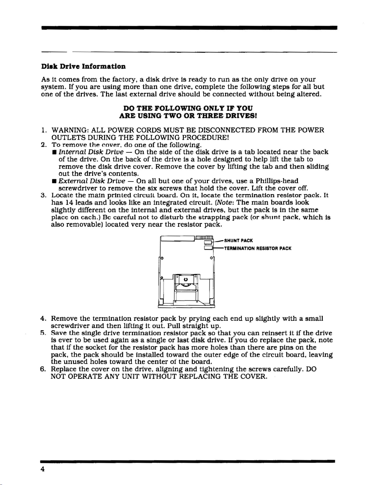
3. Locate
has
slightly
place
also
from
are
drives,
the
Disk
the
drive.
the
the
drive's
Disk
the
main
14
leads
and
different
on
each.)
removable)
the
factory, a
using
The
"over.
Drive
On
the
disk
contents
Drive
to
remove
prtnted
looks llke
on
Be
careful
located
more
last
external
DO
ARE
THE
do
-
backofthe
drive
cover.
- On all
clrcull
the
Internal
very
disk
than
THE
FOLLOWING ONLY IF YOU
USING TWO OR THREE DRIVESI
FOLLOWING PROCEDURE I
oneofthe
On
the
Remove
.
the
six
board.
an
Integrated
nottodisturb
near
driveisreadytorun
one
drive.
drive
should
BE
complete
be
connected
DISCONNECTED FROM
folloWing.
sideofthe
drive
but
oneofyour
screws
disk
Is a hole
the
cover
that
hold
On
It,
drive
designedtohelp
by
drives.
the
locate
cirCUit. (Note:
and
the
p
external
resistor
the
strapping
drives.
pack.
~
0
as
the
the
folloWing
is a
tab
llftlng
use
cover. Lift
the
termination
The
but
the
pack
SHUNT
PACK
TERMINATION
only
drive
on
steps
without
being
THE
located
the
tab
11ft
and
near
the
then
a Phl11lps·head
the
cover
resistor
main
(or
pack
shunt
RESISTOR
boards
Is In
pack.
PACK
the
your
for all
altered.
POWER
the
tab
off.
pack.
look
same
which
but
back
to
sliding
It
is
4.
Remove
screwdriver
5.
Save
the
Is
ever
tobeused
thatIfthe
pack,
the
the
unused
6. Replace
NOT OPERATE
the
termination
and
single
socket
pack
holes
the
cover
then
drive
again
for
should
toward
on
ANY
-J
'I
'I
'---
0
-
'-
resistor
llftIngItout.
termination
asasingleorlast
the
resistor
be
installed
the
the
drive,
UNIT WITHOUT REPLACING
pack
by
Pull
straight
resistor
pack
has
toward
centerofthe
aligning
prying
pack
disk
more
the
board.
and
each
up.
so
drive. If
holes
outer
tightening
end
that
you
you
than
edgeofthe
the
THE
COVER.
up
slightly
can
do
there
screws
reinsert
replace
are
circuit
carefully.
withasmall
It
If
the
the
pack.
pins
on
the
board,
leaVing
DO
drive
note
4
Page 7
Disk
The
procedure
drivels)
•
• If
follow
• If
In
Memory
you
have.
If
you
have
Internal
you
are
the
External
you
have
"Connectlng
Drive
for
setting
an
Internal
Disk
Drive."
using
directionsIn"Connecting
Disk
Drives."
oneormore
up
an
Internal
the
Controller
the
Disk
drive
disk
external
only,
CardtoExternal
Memory
see
"Connecting
drive
with
the
drives
System
oneormore
Controller
and
no
Internal
Disk
depends
the
CardtoBoth
Drives."
on
Controller
external
drive, follow
the
typeofdisk
Cardtoan
disk
Internal
drives,
the
directions
and
ConnectiD,
1.
Turn
2. WARNING: TO AVOID DAMAGING ACCESSORY CARDS. WAIT TWO
AFTER TURNING
PROCEEDING.
3.
Remove
pull!ng
4.
Carefully
compartment
off
the
the
the
up.
place
Controller Card
computer
top
from
the
now
console
OFF
THE
the
peripheral
Peripheral
should
beatthe
r:;:.-;=::::
to
an
and
allll.ttached
UNIT FOR
system
Expansion
top).
..
==..::::
Internal
THE
POWER
by
System
..
==:;;,,::::
DI.k
devlce5.
lifting
on
...
=;;;.::71\1
Drive.
TO
DISCHARGE BEFORE
the
back
edgeofthe
Its left
side
(the
\
•
5.
Two
screws
located
place
6.
Remove
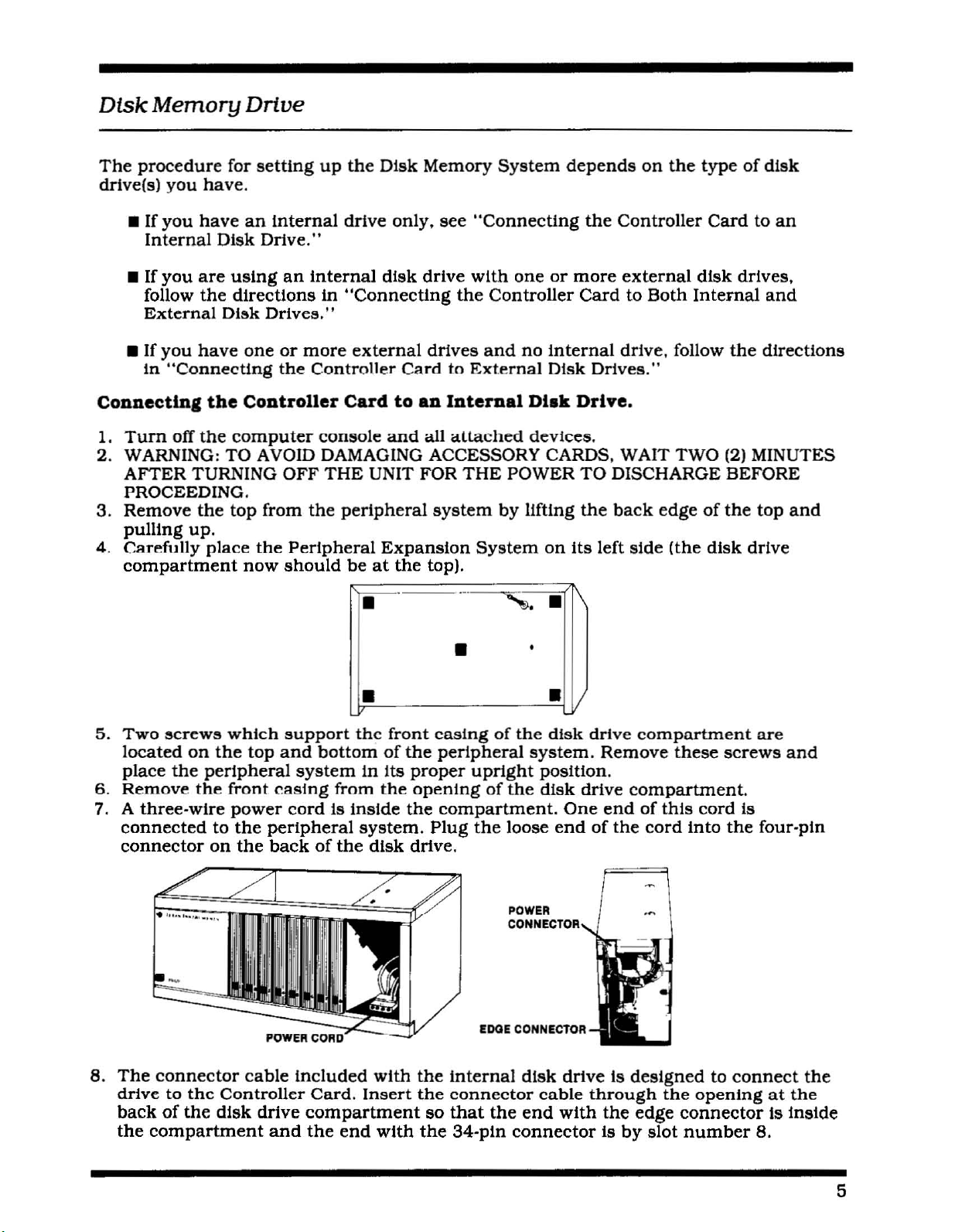
7. A
three-wire
connectedtothe
connector
on
the
which
the
top
peripheral
the
front
power
on
the
support
and
bottomofthe
system
casing
cord
peripheral
backofthe
from
Is Inside
IT·~_-----'·=j
thc
front
in
Its
the
system.
disk
casingofthe
peripheral
proper
openingofthe
the
drive.
upright
compartment.
Plug
the
loose
V
disk
system.
position.
disk
One
endofthe
drive
Remove
drive
compartment.
endofthis
compartment
these
cord
cord
Into
(2)
disk
screws
the
MINUTES
top
and
drive
are
and
Is
four-pin
8.
The
drivetothc
backofthe
the
connector
Controller
disk
compartment
cable
drive
and
Included
Card.
compartment
the
end
with
Insert
with
the
Internal
the
connector
so
that
the
34-pln
POWER
CONNECTOR
eDGE
CONNeCTOR
disk
driveIsdesignedtoconnect
cable
the
end
with
connectorIsby
through
the
edge
the
connector
slot
openingatthe
Is Inside
number
8.
the
5
Page 8

9. Next.
the
the
Controller
and
note
that
card.
On
the
frontofthe
Cardsothat
the
connector
the
label Identifying
frontofthe
peripheral
tab
system
the
faces
the
Disk Drive
cardIsan
Indicator Ught faces
the
backofthe
Indicator light.
unit
when
the
unit.
Controller
card
the
frontofthe
Cardison
The
light
can
IS active. Huld
peripheral
the
be
seen
lhe
Disk Drive
top
from
system
of
10. Carefully aUgn
of
the
peripheral
Attach
11.
sideofthe tab
Firmly
12.
take
disk
13. Attach
backofthe
14. Slide
top
peripheral
may
the
34-pln
press
up
any
slackInthe
drive
left-hand corner. Note: Align
beInupside
compartment.
the
edge
disk
the
disk
system
the
card
with
system.
connectorofthe
on
the
Controller Card.
the
Controller
cable
connectorofthe
drive.
drive
into
with
down.
the
the
r--"'7f01roJroI7Il7T::lr::'l":V--"""
CONNECTOR
slot
number8with
SUde
the
Card
holes In
Into
by
pulUng
disk
compartment
the
TAB
card
halfway
disk drive
the
slot
the
drive
so
screw
the
openings
disk drive. If
the
connector
down
cabletothe
until
excess
cabletothe
that
the
through
the
on
they
red
lUI!
• 0
tab
faCing
Into
the
slot.
34-pin
connectionIsmade.
34-pln
Indicator Ught Is In
the
do
the
connector
top
and
not
connector
opening
bottomofthe
line up.
the
Into
tab
the
back
on
the
Then
the
on
the
drive
the
F..~,
15. Again. carefully place
Included
drive In
the
proper
of
the
16. Replace
extension
nul
Du
Note:
rememberingtopress
6
with
the
peripheral
peripheral
upright
system.
the
top
on
run
the
If
the
top
the
Internal
system.
position.
on
the
the
frontofthe
system
does
..~..
~,
..;..,;...
;,,==~;;:;;;:~~~s::~2~-
the
peripheral
disk
system.
After
and
peripheral
without
not
fit properly.
down
drive.
Insert
they
insert
unit.
thc
firmly
system
These
two
are
secure.
the
system
Firmly
top
remove
until
f-t+----+-INOICATOR
on
Its left side. Two
screws
screws
place
other
[n place:
two
by
sliding
press
the
the
connectionismade.
aretobe
into
the
screwsInthe
down
the
card
the
peripheral
the
front
on
the
top
en9ures
and
SCREW
extra
usedtosecure
openings
edge
back
realign It in
on
systeminIts
openings
under
edgeofthe
proper
OPENINQS
LIGHT
screws
the
bottom
on
the
ventilation.
the
slot.
the
the
are
of
top
top.
Page 9

Disk
Memory
Drive
Connecting
1. If
your
more
internal
Instructions
2. Use
drlve(s)toyour
extends
tab
3.
Attach
cable.
4.
Each
cable
the
5. If
the
6.
Connect
first
drive)
controlIer
the
correclly.
external
the
align
external
and
adapter
you
are
middleofthe
external
should
adapter
the
Controller CardtoBoth
disk
system
drives
drive
and
In
special
from
the
will,
the
the
adapter
drive
one
near
board
using
the
endofthe
drive's
have
should
boardinorder
SPECIAL
Internal
tncludes
(Model
install
the
preceding
cable
included
system.
backofthe
holes
board
has
the
middleofthe
on
the
two
external
first
disk
second
cable.
their
be
the
CABLE-'~~;;;W~2~!Jt~~
both
PHP1850l,
the
Internal
section.
with
Connect
one
peripheral
on
the
connector
Included
an
attached
Controller's
drives,
drive's
external
All
but
termination
one
thatisnot
to
insert
an
Internal
drive
the
endofthe
with
cable
cable.
cable.
insert
cable.
the
last
packs
It.
It
first
ControlIer
system,
cable.
the
with
an
drive's
disk
removed.
modified.
goesineasilyifyou
and
disk
drive
remove
and
the
Cardtoconnect
cabletothe
making
ControlIer
two
Attach
the
adapter
cable
drive
Note:
External
(Model
the
termination
Controller
connector
sure
Cardtothe
connector,..
endofthe
board
Into
(If
The
It
into
the
adapter
you
are
drive
may
haveItpositioned
Drives
PHPl2501
Card,
following
the
that
the
other
oneatthe
disk
the
using
farthest
be
necessarytorotate
and
pack
from
external
tab
that
pins
on
endofthe
endofthe
drive
connector
boardofthe
more
from
one
the
the
cable
than
the
or
the
to
in
one
The
internal
external
disk
drive
can
be
driveinthe
drive,
the
(farthest
one
from
usedtoidentify
-=._~_.
Peripheral
connected
the
Controller) Is DSK3.
each
drive.
•
~-
--
Expansion
directlytothe
~~~
~.
~..~~
~~~
- -
-_.
~~._~
~~~
.,.
-.oJ'-==
-.~
=
Systemisconsidered
ControlIer
The
labels
Card,
provided
is DSK2.
DSK1.
with
The
The
your
first
third
drlve(s)
7
Page 10

Connecting
1.
Turn
2. WARNING: TO AVOID DAMAGING ACCESSORY CARDS, WAIT
AFTER
PROCEEDING.
3.
Remove
and
pulUng
4.
The
cardIsan
llght
backofthe
the
Controller CardtoEzternal
off
the
computer
TURNING
the
top
from
up.
labelldentlfylng
Indicator
faces
the
frontofthe
unit.
OFF
the
Ught.
console
THE
the
peripheral
Controller
Hold
peripheral
and
all
UNIT FOR
system
CardIson
the
Disk
system
CONNECTOR
attached
THE
Drive
TAB
Disk
unit
unit
r--
Drives
devices.
POWER
by
the
topofthe
Controller
and
TO
Uftlng
the
DISCHARGE BEFORE
the
back
card.
Card
so
connector
:'-~~
--.
.
IIU·
i
II'
,
• • •
.~
TWO
edgeofthe
On
that
1'--
V
the
tab
(2)
the
faces
MINUTES
top
frontofthe
Indicator
the
'"
A
5. Carefully
of
the
has
been
6.
Replace
extension
not
run
If
the
down
7.
Each
cable
drive to
8.Ifyou
middle
necessarytorotate
haveItpositioned
align
peripheral
made.
the
the
top
does
firmly
external
and
one
the
are
using
connectorofthe
thc
top
nnth..
on
the
system
not
untll
drive
near
connector
more
card
with
thc
system;
frontofthe
without
fit
the
the
the
correctly.
firmly
peripheral
unit.
the
properly,
connectionIsmade.
has
an
attached
middleofthe
tab
on
the
than
one
first
and
adapter
desired
press
system
Firmly
top
remove
Controller
external
second
boardInordertoInsert
slotsothat
the
card
by
press
In place;
the
cable
with
cable.
drive,
disk
down
sUdlng
the
card
Attach
Card.
Insert
drive's
the
down
top
ensures
and
realignItIn
two
connectors,
the
the
connector
Into
the
front
on
the
endofthe
an
adapter
cable.
Note:
It. It
slot
edge
back
proper
the
oneatthe
cable
board
It
goe..In
tab
face..the
untll
connection
under
edgeofthe
may
easllyIfyou
the
ventilation.
slot,
pressing
on
Into
be
back
top. Do
Note:
endofthe
the
disk
the
8
Page 11

Disk
Memory
Drive
9.
Having
away
the
cable.
you
the
The
first drive,
by
TI BASIC.
drive
removed
from
second
The
have
one
that
Is DSK3.
the
the
Controller),
drive's
third
cable
driveIsconnected
twoorthree
has
not
the
one
connected
The
second
The
labels
L~I
-I
Ilr"tl
termination
connect
plugs
drives,
been
drive,
provided
the
modified.
connected
~_:::~::~:
packs
the
Into
the
to
drive
directlytothe
with
your
':I~-~
~--=-=
~
- .
=-=
~~~-~
.--
..~.•
...
<-
•
all
>.
but
_~
....,~
--
--
from
drivesInseries.
adapter
the
second
farthest
boardinthe
driveInthe
away
Controller
to
the
cableofDSKl,
drivels)
can
III1i,W!L
....-....-..
,,_:>
c.--•
the
from
last
drive (the
The
connector
middleofthe
same
the
controller
Card,
Is IdentifiedasDSKI
Is DSK2.
be
usedtoIdentity
one
way.
farthest
on
the
first
Whether
should
The
each
end
third
of
drive's
be
drive.
Always
before
connecting
disconnect
moving
the
the
console
designedtosupport
prevent
moving
long
Peripheral
their
damage,
any
distance
Expansion
original
always
partofyour
moves,
packing
CAUTION
the
Peripheral
computer
and
the
weightofthe
disconnect
Home
remove
System
material.
Expansion
cOl1sol".
peripheral
Computer
all
cards
and
repack
System
Th"
cable
systemIsnot
units.
all
To
devices
system.
from
the
the
before
For
devices
In
9
Page 12

Starting
the
System
After
and
the
outlets.
any)
and
turn
on
the
Controller
drives
Next,
then
the
Card
have
tum
on
the
switch
peripheral
Each
follow
1.
2.
3.
For
Peripheral
computer
disk
module
console
ordertorestore
been
the
system.
time
Turn
Turn
Then
proper
drives,
has
been
fn"",rt"d Into
connected,
power
on
the
the
you
this
puwer-up
on
the
on
the
turn
on
memory
plug
switches
frontofthe
Internal
operate
external
Peripheral
the
allocation
Expansion
consoleIsswitched
Controller
wlll
not
function
must
be
turned
normal
the
power
on
the
peripheral
disk
driveIsautomatically
WARNING
your
computer/disk
sequence;
disk
drives.
Expansion
monitor
and
by
System
must
on.
Card,
and
correctly.
off
and
operation.
the
Peripheral
cords
Into
backsofyour
system
System
computer
the
computer,
be
ON
Otherwise.
Disk
Manager
The
computer
turned
back
Expansion
your
external
unll.
system,
unit.
console.
when
the
on
In
electrical
Note:
turned
the
the
System
disk
When
wall
drives
you
on.
unit
(If
When
then
Turn
you
go
off all
properly.
turn
off. If
units
on
they
the
stay
and
console,
on,
the
make
sure
the
disk
that
disk
drive
the
drives'
working
cableIsprobably
disk
drive
cable
lights
may
plugged
connections
come
on
In uplSlde
have
briefly
down.
been
and
made
10
Page 13

Disk
Memory
Drive
CARING FOR DISKETTES
1.
2.
Handle
surface;
De
the
careful
diskette
fingerprints
nottobend
by
wl1l
Its
the
protective
destroy
diskette.
cover. Do
disk
contents.
not
touch
any
partofthe
diskette's
3. Do
4. Do
5. Do
6, Do
7. Do
not
write
pen.
not
scratch
may
destroy
informationtobe
not
expose
not
place
not
removeadiskette
on
the
diskette
the
surfaceofthe
all
the
information
lost
lrom
diskettestomagnetic
tapeofany
cover
mostofthe
kind
(maskingorother)
from"
withaball-point
diskette.
onanumberofsectors.
l1eldsorexcessive
drive If
flies
the
Any
UIl
drive
penorpencil;
scratch,
lhe
dl5kette.
on
the
lightison.
eveniftoo
This
usually
heat
or
cold.
surfaceofa
only
small
causes
diskette.
use
to be
a felt-tip
seen,
11
Page 14

IN
CASE OF DIFFICULTY
If
the
disk
1.
Power
the
the
2,
Card
peripheral
system
- Be
proper
console
Po'<,ition -
does
sure
sequence:
and
system.
top.
3.
Cable
for loose
-
Checktobe
or
broken
side up.
4.
Peripheral
and
peripheral
5.
Home
accessories
6. If
noneofthe
Questions
sectionofthe
Expansion
Computer
disconnected.
above
or
Need
User's
system.
not
all devices
disl<
the
monitor,
Turn
the
Verify
sure
leads.
System
-
Checktosee
procedures
Assistance"
Reference
appeartobe
are
plugged
drives
power
that
that
all
the
and
off.
cards
Checktosee
-
Check
that
corrects
or
see
Guide.
working
Peripheral
walt
are
proper
that
for
the
the
the
properly,
in,
Then
tum
Expansion
two
minutes,
Inserted
cables
the
proper
Home
properly
are
cables
connection
Computer
difficulty,
"Maintenance
check
on
and
being
are
consult
and
the
the
powertothe
System
remove
and
used.
'Check
properly
between
works
"If
Service
following:
f1
....
t,
followed
the
topofthe
then
replace
the
connected,
the
properly
You
Have
Information"
units
the
cables
right
console
with
In
by
all
12
Page 15

Disk
Memory
Drive
EXCHANGE
If
some
facility for
reconditioned
establlshed
center
rates
information
To
Exchange
Calculator
center
Department
partofyour
for
In effectatthe
determineIfthereisan
for
CENTERS
repairorreplacement,
unit
across
in-warranty
and
the
Center
and
availability
for
in
Adding
further
(LOCAL SERVICE OPTIONS)
disk
system
by
goinginperson
the
United
exchanges.
timeofthe
locationofthe
exchange
the
white
Machine
and
exchange
details
requires
you
States.Ahandllng
Out-of.warranty
exchange.
nearest
pagesofyour
heading
and
the
service,
may
electtoexchangeItfor a
to
oneofthe
Please
exchange
centerinyour
telephone
in
the
fee
Information.
locationofthe
instead
exchange
fee wlll
.,xch,,"g.,~
refertothe
area,
yellow
of
be
center.
look for
directory,
pages.
Write
the
nearest
charged
returningittoaservice
factory
centers
will
enclosed
Please
Consumer
exchange
by
be
Texas
or
look
call
which
the
exchange
charged
exchange
Instruments
under
the
Relations
center.
has
been
at
the
fee
the
exchange
13
Page 16

IF YOU
If
you
software
(toll free
Texas.
For
HAVE
have
purchase.
within
The
technical
questions
operators
806-741-2663.
accepted.
As
an
alternative.
QUESTIONS OR
concerning
please
the
contiguous
at
these
questions
Please
you
Consumer
Texas
P.O. Box
Lubbock.
"hout
note
can
Relations
Instruments
53
Texas
NEED
disk
call
our
Consumer
United
numbers
programming.
that
thisIsnot
write
to:
Department
Incorporated
79408
ASSISTANCE
system
repairorperipheral.
Relations
States
cannot
except
prOVide
specific
a toll-free
accessory.
Department
at
800-858-4565
T"xa"jor800-692-4279
technical
application.
number.
assistance.
etc..you
and
collect calls
within
can
or
call
cannot
be
Becauseofthe
sources
suggestions
containing
onlyIfthey
Instruments
share
language
your
your
letter:
suggestions
program
number
to
refusetoreceive
"All
of
Instruments
uf ISuggestions
both
new
are
with
which
you
the
information
onanonconfldentlal.
and
old Ideas.
freely given to
any
Texas
have
Instruments.
developed.
forwarded
confidentialorotherwise.
Instruments
distribute.
without
by
this
publish.
reproduce.ordisposeofthe
compensation
presentation.
to
which
cometoTexas
Texas
Texas
Instruments
Instruments.ItIs
Instrument..from
suggestion..In confidence.
orIfyou
please
wish
Include
herewithispresented
nonobligatory
expressed
or
implied.Isestablished
Texas
Instruments
informationInany
me."
will
consider
the
polleyofTexas
Therefore.Ifyou
ustoreview
the
following
to
Texas
basis;
no
relationship.
may
use.
many
such
wish
any
BASIC
statement
with
Texas
copyright.
way
to
in
Page 17

Disk
THREE-MONTH LIMITED WARRANTY
Memory
Drive
THIS
THE
TEXAS
ORIGINAL CONSUMER PURCHASER
INSTRUMENTS
DISK
MEMORY DRIVEWARRANTY
WARRANTY DURATION
This
DiskMemoryDrive is
purchasebythe
consumer.
warranted
for a period
WARRANTY COVERAGE
This
DiskMemoryDrive is
WARRANTY
UNREASONABLE
ARISINGOUT
WARRANTYDISCLAIMERS
ANY
IMPLIEDWARRANTIESARISING OUTOFTHIS
LIMITEDTO
FORA PARTICULAR
THREE-MONTH PERIOD.
OF
USE
EXPENSES.
Some
statesdonot
damages.sothe
OF
18
VOID Ill'
OF
THE
THE
OR
DAMAGES
above
USE.
DEFECTSINMATERIALS
IMPLIEDWARRANTIES OR MERCHANTABILITY
DISK
allow
warranted
THE
ACCESSORY
NEGLECT. IMPROPERSERVICEOROTHER
PURPOSE.
TEXAS
DRIVEOROTHER INCIDENTALORCONSEQUENTIAL COSTS.
INCURRED
the
exclusionorlimitationof implied
lim
Ilations
against
ARE
LIMITEDINDURATIONTO
INSTRUMENTS
BY
or
exclusions
OF
THE
ofthree
defective
HAS
BEEENDAMAGED
OR
WORKMANSHIP.
THE
CONSUMERORANYOTHER
may
not
EXTENDS
ACCESSORY.
(3)
months
from
the
date
materialsorworkmanship.
BY
ACCIDENT.
CAUSES
SALE.
SHALL
INCLUDING
THE
NOT
BE
AND
ABOVE
LIABLEFOR
warrantiesorconsequential
apply
to you.
TO
of original
THIS
NOT
BUT
NOT
FITNESS
LOSS
USER.
LEGALREMEDIES
This
from
warranty
state
gives
to state.
you
specific legal rights.
WARRANTY PERFORMANCE
During
module
model (at TI'soption)
Servtce Facility listed below.
months
wUlbemade
TEXAS
U.S.
Texas
2303
Lubbock.
ConsumersinCalifornia
additional
Texas
831
El
(213)973·1803
the
above
will be repairedorreplaced
from
dateofrepairorreplacement.
for
INSTRUMENTSCONSUMERSERVICEFACILITY
Residents
Instruments
North University
Texas
assistanceorini"ormation.
Instruments
South
Segundo.
Duuglas
CA
three-month
when
the
The
the
repatrorreplacementofIn-warranty unIts.
ServiceFacility
79415
and
Oregon
Consumer
Street
90245
and
you
warranty
period.
your
withaneworreconditioned
unitisreturned
by
prepaid
repairedorreplacement
Other
than
Canadian
GeophysicalServicesIncorporated
41 ShelleyRoad
Richmond
may
contact
the
Texas
Service
6700
KrIstin
Beaverton. Oregon
(503)643-6758
may
also
ha
DiskController
unit
shipment
unit
will be
the
postage
Residents
Hm.
Ontario.
following
Texas
Instruments
Southwest
Square.
105th
Suite
VI:
oUler
J"1ghts
and
Disk Manager
ofthe
toa
same
Texas
warranted
that
vary
or equivalent
Instruments
for
three
requirement.nocharge
Canada
Instruments
Consumer
110
L4C5G4
offices for
Service
97005
15
Page 18

Ti!'ra.<
the
Instruments
microprocessor.
Belngjlrst
Invented
and
Is
our
the
Intearated
the
microcomputer.
tradlllon.
circuli.
PRINTED
IN
u.s
.....
TEXAS
INSTRUMENTS
INCORPORi\lrO
Page 19

ADDENDUM
Disk Memory System and Disk Memory Drive Manuals
Connecllng
The
Installation directions givenonpages 9 and 10ofIhe
pages 5 and 6 of the
connect
1.
Turn
2.
WARNING:TOAVOID DAMAGING
TURNING
3.
Remove
top and pulling up.
4.
Two Philllps·head screws allach the front casingofthe disk drive compartment. One
locatedonthe topatthe peripheral system, and the other Isonthe
Remove
5.
Carefully place the Peripheral Expansion SystemonIts left side (the disk drive compartment
now should
Note:
Peripheral Expansion System.
lhe
Conlroll.r
It to the COntroller Card, please follow the procedure lIated
off the computer console and all allached devices.
OFF
THE
tha top from the peripheral systembydepressing the latchesonthe back edgeofthe
the top screw.
be
at the top).
Save
the screws to secure the Internal disk driveInplace after It Is Installed In the
C.rd10.n
TI
Disk Memory Drive manual are Incorrect.
UNIT
FOR
Remova
Inl.mal
ACCESSORY
THE
tha
Disk
Drlv.
POWERTODISCHARGE
.crewonthe bollom of the peripheral syslem.
-~---~,
•
CARDS,
•
TI
Disk Memory System manual and
To
installanInternal drive and
here.
WAIT
TWO
(2)
BEFORE
MINUTES
PROCEEDING.
DeHorn
AFTER
of the unit.
i
•
on
Is
IOTTo.VlIW
r
•
6.
Place the peripheral systemInIts proper upright position, and remove the front casing from
the opening of the disk drive compartment.
the Internal disk drive from the Peripheral Expansion System later.)
7.
Two flexible cables are packed with the Controller Card: oneIsfor connecting an Internal diSk
drive, and the other
types of connectors at each end; this Is tha cable used10connect the Controller Card10the
Internal drlva.
drives.)
Examine the connnector tab on the side
the Internal disk drive conneclor cable. Nole Ihe proper orlenlatlon of Ihe Iwo;
to connect tbem througb a
IsInplace.
one
way.
8.
Next, note
On
Ihe front of the cardIsan'
peripheral syslem unit when the cerd
Copyright ©
.....
_._..,_
• I'"•
1982
The
thatlhe
by
Teu.
Is
for connecting external drives. Locate the cable which has
(Sava
tbe cable withId..nlical connectors at each end for connecting external
of
the Controller Card and the 34-pln conneclor
0101altbe backofIha drlva compartment afler Ihe Controller Card
lab and the 34·pln connector are keyedsothat Ihey can onlybeoonnected In
label Identifying Ihe Disk Drive Controller CardIson
In.trumentllncofl)Orated
Indicator light.
Is
active.
•
(Save
the tront casingIncase you want to
The
light canbeseen from the 'rant0'the
the
IUNwith '0383-I5-2aod
dlffer.nt
you
will
lopofthe card.
r.mov.
on
have
'0603'0.2
'030353-11
Page 20

ADDENDUM
IIIIDIC;AToa LIGHT
9.
Hold the Disk Drive Controller Cardsothat the Indicator light faces the front of the peripheral
system
number 8
but the
10.
Attach the 34·pln connector of the disk drive cable to the 34·pln connectoronthe side of the
tabonthe Controller Card.
this. (If
conneclorasyou
11.
A four·wire power cordIsinside the compartment.
peripheral system. Plug the loose
the disk drive. This connector is also keyed to fit only one
and
the connector tab faces the back of the unit. Carefully align the card with slot
and
press down firmly until the card isInplace.
cable
thon Interferes with
you
look down into the Peripheral Expansion System from the top,
You
will
other
have
slots.)
to reach through the disk drive compartment to
(The
card canbeplacedInany slot,
you
can see the
make Ihe connectlun.)
One
end
of this cordIsconnected to the
end
of the cord Into the four·pin connectoronthe back of
way.
. ,
do
POWEll
CONHfCTO"
EOGE
COHHfCTOfil
12.
Attach the edge connector of the disk drive cable to the 34·pin connector tabonthe back of
the disk drive.
13.
Two screws hold the cover of the disk driveInplace.
head
screwdriver,
14.
Slide the disk drive into the compartment so that the
corner.
the holes
Note:
In
and
save
the screws for installing the disk drive.
Align the screw openlnos nn
In"
the disk drive.Iftheydonot line
top
up,
Remove
red
and
bottom of the parlpheral system with
Ihese screws, using a Phillip.·
indicator light is in the lop left·hand
the drive maybein
_t-_+_IHOlCATOR
upside down.
LIGHT
Page 21

ADDENDUM
15.
Again, carefully place the peripheral system on its lett side. Using the screws removed from
the front casing and the disk drive cover, Insert two screws into the openings
of the peripheral system.
upright position, and insert the other two screws
16.
Replace the top on the peripheral systembySliding the front edge under the extensiononthe
front of the unit. Firmly press down
Without
the
top
In plaC8j the
Aft"r
they are secure. place the peripheral system in Its proper
on
lop
the back edge of the top.Donot
ensures proper ventilation.
In
the openingsonthe top of the system.
Note:
If the top
properly, remove the card and realign ItInthe slot, remembering to press down firmly until
the connection
IMPORTANT
service,
REMOVE
NOTE:
Is
made.
If either the Peripheral Expansion System or the Internal disk drive require repair
THE
INTERNAL
DRIVE
FROM
THE
PERIPHERAL EXPANSION
SEPARATE PACKING AND SHIPPING. Shipping the disk drive Inside the Peripheral Expansion
System can damage the drive.
run
the system
does
SYSTEM
on
the bottom
not tit
FOH
Inltl.llzlng
Dlak.tt.a
During diskette Initialization, the Disk Manager Command Module asks for certain information that
Identifies the types of disk controller, disk drives, and diskettes
TRACKS
TheTIDisk Drive Controller Card, Model Number
density data per diskette side.
whether
When you respondtothe prompt TRACKS
support
side. " yours is one of these. enter
In
PER
SIDE?,
or not you
40
tracks per diskette side. However, some older drives may support only35tracks per
SINGLE SIDED
can
writetoand
answer to the prompt SINGLE
(YIN)?,
The
type of disk drive
rGad
from
3S
in response to this prompt.
SIDED
(YIN)?,
and SINGLE DENSITY
PHP
1240,
and
both
sld8sofIhe
PER
SIDE?,
press Y
enter40in most cases. Most disk drives
and
you
are
using. These prompts are
(YIN)?
supportsupto40tracks of single-
diskette you are using determines
diskette.
then
ENTER
If you are using a single-
sided disk drive. If both your diskette and disk drive are double-sided, enterN.(For more
information about diskette types, see page 5 of the
71
Disk Memory System manual and your disk
drive manual.)
.
In
response to the prompt SINGLE DENSITY
supports only single-density data. Although double·density diskettes and disk drives may
with the controller,
data
will onlyberf:!!c.;oruetJ
Diskette initialization is referencedonpages
(YIN)?,
enter Ysince theTIDisk Drive Controller Card
in single-density format.
17,
24,
25,
and26of the Disk Memory System
be
used
manual.
 Loading...