

Page 1
Peripheral Explorer Kit Overview
Quick Start Guide
SPRUGM2 – January 2009
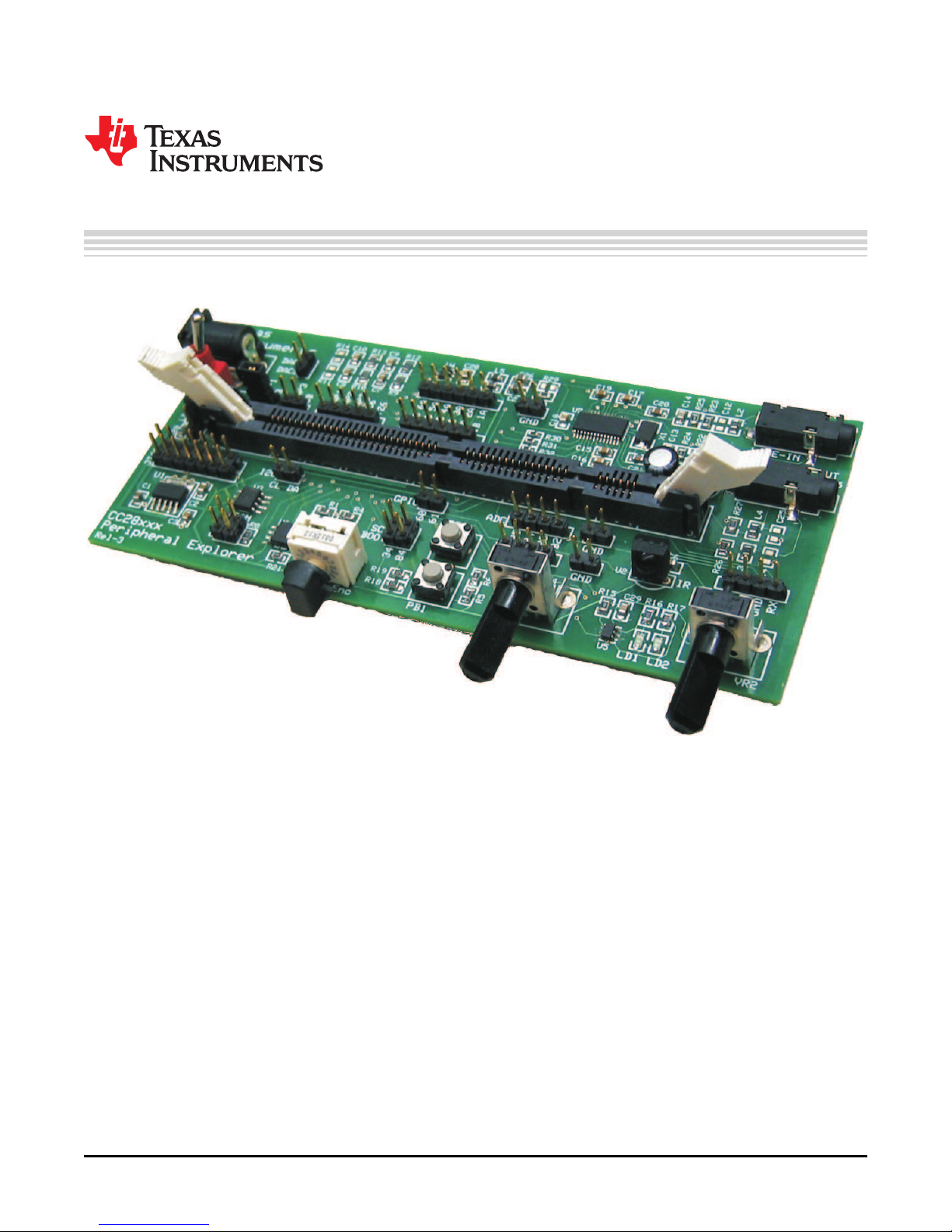
The Peripheral Explorer Kit is an evaluation board designed to allow experimentation with many of the
peripherals available in the C2000™ F28x family of microprocessors. The board is designed to accept any
of controlCARD and contains all hardware (controlCARD socket, power supply) required for normal usage.
The kit is self-contained and contains multiple experiments in which external equipment, such as
oscilloscopes, are not required. In the majority of these examples, one peripheral reads the output of a
different peripheral, confirming the operation of both.
SPRUGM2 – January 2009 Peripheral Explorer Kit Overview 1
Submit Documentation Feedback
Page 2

Features of the Peripheral Explorer Kit include:
• Multiple peripheral-based examples
– EPWM-based sinusoidal output based on a sine table
– DAC via filtered ePWM signal read by the on-chip ADC
– eCAP-based IR receiver reading
– SPI-based EEPROM interaction
– UART communications header available for host control
– Potentiomers for ADC evaluation
– GPIO-based components such as pushbuttons, hex encoder, and LEDs
– McBSP/DMA-based AIC23 codec software and hardware (F28335 only)
– I2C header for external use
– CAN header for external use
• Quick Start GUI, a friendly way to control / demo the application, based on open
source C# freeware
• Hardware Developer’s Package is available and includes full hardware
documentation such as schematics, bill of materials, and Gerber files.
www.ti.com
Peripheral Explorer Kit Overview2 SPRUGM2 – January 2009
Submit Documentation Feedback
Page 3
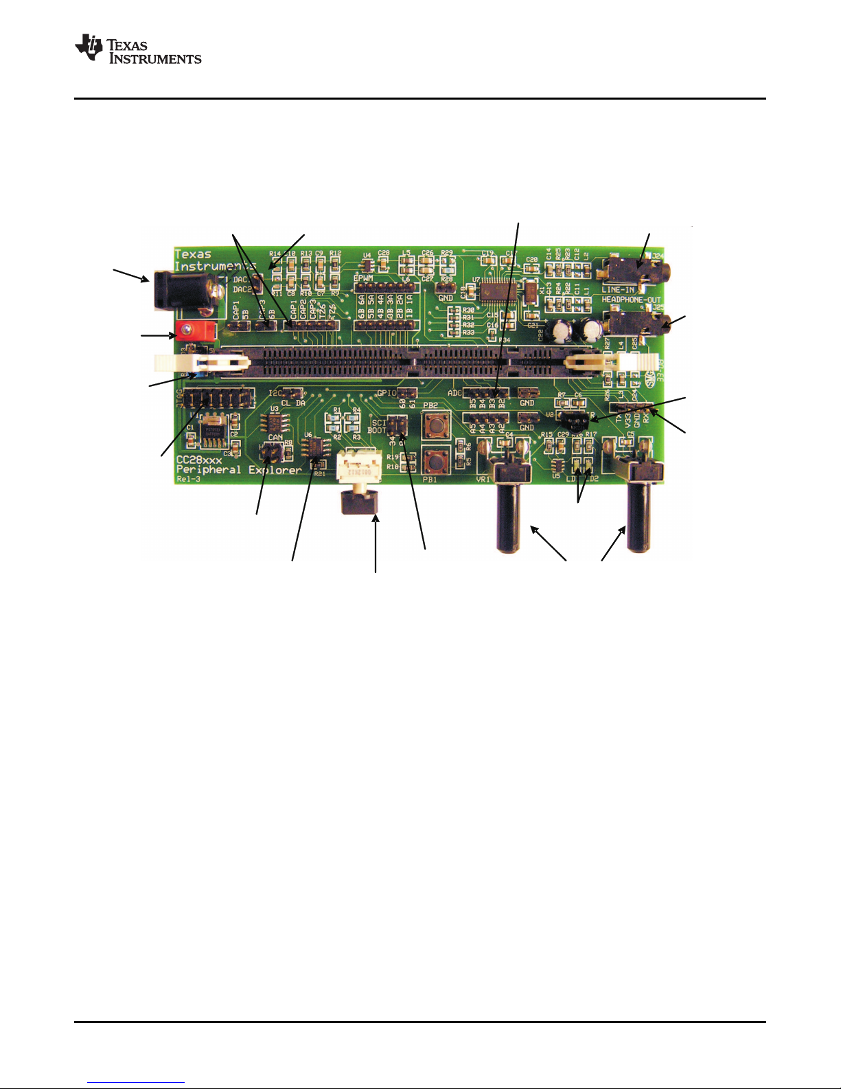
Potentiometers(ADC)
LEDs(GPIO)
CAN
JTAG
MainPower
(SW1)
+5VPowerIn
EEPROM
(SPI)
HexEncoder
(GPIO)
SCIBootPins
EPWMtoECAP
loopbackenable
DACoutput
(EPWM)
ADCPins
Audio-In
(McBSP)
Headphone-
Out
IRReceiver
(ECAP)
Comms(SCI)
Emulator
PowerJumper
www.ti.com
1 Hardware Overview
Hardware Overview
The Peripheral Explorer Kit consists of multiple peripheral based components. Figure 1 shows a diagram
of the Peripheral Explorer board and some of its key features.
Figure 1. Key Features of EVM Board
SPRUGM2 – January 2009 Peripheral Explorer Kit Overview 3
Submit Documentation Feedback
Page 4

Hardware Overview
www.ti.com
Table 1. Hardware Components
Component Description
+5V Power In DC power supply from plug pack (5-V supply may be used as well)
Main Pwr SW1 - Master power switch for entire EVM
Emulator Power Jumper Sets the voltage sent to power the emulator. No jumper means no power will be sent to an emulator, a
JTAG Connector for external JTAG emulator
CAN External pins available for connection to two parallel CAN devices
EEPROM 256K SPI-based EEPROM
Hex Encoder 4-bit hex encoder which sets the values of GPIOs 12-15
SCI Boot Pins Controls how the controlCARD boots
Potentiometers Divide a 3.3-V input into a voltage value to be read by ADC-A0 and ADC-A1
LEDs LED1 and LED2 controlled by GPIO-09 and GPIO-11
Comms Serial communications UART (connects to the Quick Start GUI)
IR Receiver Uses the eCAP module to read signals sent by a IR transmitter. The software included with this kit is
Headphone-Out Output from the TI AIC23B codec that is controlled by the F28x MCU (headphones not included in this
Audio-In Input to the TI AIC23B codec (line-in audio cable not included in this package)
ADC pins Spare ADC pins available to be connected as desired
DAC output Output of a filtered ePWM. The ePWM output is connected to a second-order passive filter then
EPWM to ECAP Connecting a jumper across these headers allows for an experiment to be done where the eCAP
loopback enable module reads the duty cycle and period of the ePWM output
jumper at “5V” will power the emulator with 5 V, and a jumper at “3V3” will power the emulator with 3.3
V.
If no jumpers are placed the target boots from flash
If a jumper is placed at “34”, a F2808 controlCARD boots from SCI
If a jumper is placed at “84”, a F28335 controlCARD boots from SCI
configured to work with the Sharp TV protocol, for the included Philips universal remote this is code
0509.
package)
connected to these pins
Peripheral Explorer Kit Overview4 SPRUGM2 – January 2009
Submit Documentation Feedback
Page 5

www.ti.com
2 Hardware Set Up
All the hardware needed to get started (except the emulator) is included in this package (suggested
emulators are listed near the end of this document). The application specific motherboard provided in this
kit can be used in one of two ways:
1. Test Drive – Using the provided GUI application, the user does not require Code Composer Studio™
or emulation tools. This provides a great way to run or demo the application code quickly and see what
functionality the hardware offers. Note: The same functionality can be achieved by using the Code
Composer Studio Watch Window and slider features during emulation in the second mode.
2. Code Composer Studio Software Development Platform – With the project code provided, the
application can be modified, compiled, loaded, and run in a development environment. Code
Composer Studio and Emulation HW tools are required for this.
Follow these steps to set up the hardware for either the GUI or Software Development Platform
Step 1. Unpack the DIMM style controlCARD.
Step 2. Spread open the winged retaining clips on connector J2.
Step 3. Sit the DIMM card loosely in the connector slot. Make sure to align the 2 keyed notches and
Step 4. Push vertically down using even pressure from both ends of the card until the clips snap and
Step 5. Ensure switch 1 (SW1) is in the off position and connect the included power supply to the
Hardware Set Up
position the card bottom corners inside the retaining clips (see picture below).
lock. (note: to remove or eject the card spread open the retaining clips with thumbs).
power jack .
2.1 Test drive with GUI – (skip if you need only emulation support)
Step 1. Plug in the serial cable provided to connector J4 making sure the red wire aligns with the “Rx”
pin on EVM.
Step 2. Inserted a jumper in position 84 on boot pins.
Step 3. Plug the DB9 connector into your PC using either a serial port or a serial-to-USB converter
dongle.
Step 4. Turn on the power once you are done with the TI Software download, see Software Setup
GUI-TestDrive.
2.2 Code Composer Studio Software Development Platform Emulation - Additional Steps
Step 1. Depending on your emulator type, place the jumper at J2 to either the 3.3V or 5V position
Step 2. Connect the JTAG emulator cable to connector J1
Step 3. Turn on power once you are done with the TI Software download, see Software Setup Code
Composer Studio-Development.
Note: For full details (schematics, pin-out table) of the hardware see the Hardware Developer's
Package, PeripheralExplorer-HWdevPkg. See Software Setup for download location.
SPRUGM2 – January 2009 Peripheral Explorer Kit Overview 5
Submit Documentation Feedback
Page 6

Software Set Up
3 Software Set Up
The Peripheral Explorer Kit application software example, GUI, step-by-step lab style documentation, and
other useful soft collateral can all be found on the TI website. If you already have your own software
project and do not require this collateral, skip this section. As explained in the HW setup section, the
target mother board can be run either with the GUI or Code Composer Studio. The GUI executable file is
found as part of the main software download. Follow the steps below for either case.
To run any of the application specific software in Code Composer Studio, you must first install the baseline
code which contains the header files, libraries, etc. If you already have the base-line software installed,
skip the baseline install steps and go to the Peripheral Explorer Kit section.
To download the free TI soft collateral follow these steps:
Step 1. Baseline soft collateral and hardware documents (skip this if you already have this software
www.ti.com
installed)
a. On an Internet browser type: http://www.ti.com/f28xkits
b. At the C2000 DSP collateral page, choose the Experimenter’s Kit download link
c. When prompted, fill in the TI customer registration details and click ok
d. Save the .zip file to the directory of your choice
e. Unzip the file and run the install program Baseline Software Set Up
f. The installer will create the following default directories:
C:\TI_F28xxx_SysSW
~Docs
~GeneralPurposeGUI
~SupportFiles
FlashingLeds
C:\TI_F28xxx_SysHW
CC280xxHWdevPkg
CC2833xHWdevPkg
DockingStnHWdevPkg
Step 2. Peripheral Explorer Kit soft collateral and hardware documents
a. On an Internet browser type: http://www.ti.com/f28xkits
b. Then choose the Peripheral Explorer Kit link.
c. When prompted, fill in the TI customer registration details and click ok.
d. Save the .zip file to the directory of your choice.
e. Unzip the file and run the install program Peripheral Explorer Software Set Up.
f. The installer will create the following default directories:
C:\TI_F28xxx_SysSW
PeripheralExplorer
~Docs
~GUI
C:\TI_F28xxx_SysHW
PeripheralExplorer-HWdevPkg
6 Peripheral Explorer Kit Overview SPRUGM2 – January 2009
Submit Documentation Feedback
Page 7

www.ti.com
4 Running the Application
5 Emulators
Running the Application
To run the application specific hardware, choose either “TestDrive-GUI” or “Code Composer
Studio-Development” options below and follow the appropriate steps.
Step 1. TestDrive-GUI
a. Open the GUI Quick Start Guide, QSG-PeripheralExplorer-GUI.pdf, found in:
C:\TI_F28xxx_SysSW\PeripheralExplorer\~Docs
b. Browse to the directory: C:\TI_F28xxx_SysSW\PeripheralExplorer\~GUI
c. Open PeripheralExplorer-GUI.exe
d. Follow the step-by step instructions found in the GUI Quick Start Guide
Step 2. Code Composer Studio-Development
a. If you have emulation tools and Code Composer Studio already installed and active, load
the project file "PeripheralExplorer.pjt" found in:
C:\TI_F28xxx_SysSW\PeripheralExplorer\
b. See the PeripheralExplorer.pdf for a step-by-step walk through of how to compile and run
the various labs. This document can be found in:
C:\TI_F28xxx_SysSW\PeripheralExplorer\~Docs\
The following companies provide low cost, full featured emulators designed specifically for C2000™
controllers:
Blackhawk™ USB2000 Controller (part number $299
http://www.blackhawk-dsp.com TMDSEMU2000U)
Spectrum Digital XDS510LC JTAG Emulator (part number $249
http://www.spectrumdigital.com 701902)
6 References
For more information, see the following guides:
• PeripheralExplorer – provides detailed information on the Peripheral Explorer C/asm project
C:\TI_F28xxx_SysSW\PeripheralExplorer\~Docs\PeripheralExplorer.pdf
• QSG-PeripheralExplorer-GUI – gives an overview on how to quickly demo the PeripheralExplorer
project using an intuitive GUI interface.
C:\TI_F28xxx_SysSW\PeripheralExplorer\~Docs\QSG-PeripheralExplorer-GUI.pdf
• PeripheralExplorer-HWdevPkg – a folder containing various files related to the hardware on the
Peripheral Explorer board (schematics, bill of materials, Gerber files, PCB layout, etc). All schematics
and PCB files were created with the freeware ExpressPCB package.
C:\TI_F28xxx_SysHW\PeripheralExplorer-HWdevPkg\
• System Framework Overview Guide – presents more information on the system framework found in
F28xxx EVM projects.
C:\TI_F28xxx_SysSW\~Docs\SystemFrameworkOverview.pdf
• F28xxx User’s Guides
http://www.ti.com/f28xuserguides
Trademarks
C2000, Code Composer Studio are trademarks of Texas Instruments.
Blackhawk is a trademark of EWA Technologies, Inc.
SPRUGM2 – January 2009 Peripheral Explorer Kit Overview 7
Submit Documentation Feedback
Page 8

IMPORTANT NOTICE
Texas Instruments Incorporated and its subsidiaries (TI) reserve the right to make corrections, modifications, enhancements, improvements,
and other changes to its products and services at any time and to discontinue any product or service without notice. Customers should
obtain the latest relevant information before placing orders and should verify that such information is current and complete. All products are
sold subject to TI’s terms and conditions of sale supplied at the time of order acknowledgment.
TI warrants performance of its hardware products to the specifications applicable at the time of sale in accordance with TI’s standard
warranty. Testing and other quality control techniques are used to the extent TI deems necessary to support this warranty. Except where
mandated by government requirements, testing of all parameters of each product is not necessarily performed.
TI assumes no liability for applications assistance or customer product design. Customers are responsible for their products and
applications using TI components. To minimize the risks associated with customer products and applications, customers should provide
adequate design and operating safeguards.
TI does not warrant or represent that any license, either express or implied, is granted under any TI patent right, copyright, mask work right,
or other TI intellectual property right relating to any combination, machine, or process in which TI products or services are used. Information
published by TI regarding third-party products or services does not constitute a license from TI to use such products or services or a
warranty or endorsement thereof. Use of such information may require a license from a third party under the patents or other intellectual
property of the third party, or a license from TI under the patents or other intellectual property of TI.
Reproduction of TI information in TI data books or data sheets is permissible only if reproduction is without alteration and is accompanied
by all associated warranties, conditions, limitations, and notices. Reproduction of this information with alteration is an unfair and deceptive
business practice. TI is not responsible or liable for such altered documentation. Information of third parties may be subject to additional
restrictions.
Resale of TI products or services with statements different from or beyond the parameters stated by TI for that product or service voids all
express and any implied warranties for the associated TI product or service and is an unfair and deceptive business practice. TI is not
responsible or liable for any such statements.
TI products are not authorized for use in safety-critical applications (such as life support) where a failure of the TI product would reasonably
be expected to cause severe personal injury or death, unless officers of the parties have executed an agreement specifically governing
such use. Buyers represent that they have all necessary expertise in the safety and regulatory ramifications of their applications, and
acknowledge and agree that they are solely responsible for all legal, regulatory and safety-related requirements concerning their products
and any use of TI products in such safety-critical applications, notwithstanding any applications-related information or support that may be
provided by TI. Further, Buyers must fully indemnify TI and its representatives against any damages arising out of the use of TI products in
such safety-critical applications.
TI products are neither designed nor intended for use in military/aerospace applications or environments unless the TI products are
specifically designated by TI as military-grade or "enhanced plastic." Only products designated by TI as military-grade meet military
specifications. Buyers acknowledge and agree that any such use of TI products which TI has not designated as military-grade is solely at
the Buyer's risk, and that they are solely responsible for compliance with all legal and regulatory requirements in connection with such use.
TI products are neither designed nor intended for use in automotive applications or environments unless the specific TI products are
designated by TI as compliant with ISO/TS 16949 requirements. Buyers acknowledge and agree that, if they use any non-designated
products in automotive applications, TI will not be responsible for any failure to meet such requirements.
Following are URLs where you can obtain information on other Texas Instruments products and application solutions:
Products Applications
Amplifiers amplifier.ti.com Audio www.ti.com/audio
Data Converters dataconverter.ti.com Automotive www.ti.com/automotive
DLP® Products www.dlp.com Broadband www.ti.com/broadband
DSP dsp.ti.com Digital Control www.ti.com/digitalcontrol
Clocks and Timers www.ti.com/clocks Medical www.ti.com/medical
Interface interface.ti.com Military www.ti.com/military
Logic logic.ti.com Optical Networking www.ti.com/opticalnetwork
Power Mgmt power.ti.com Security www.ti.com/security
Microcontrollers microcontroller.ti.com Telephony www.ti.com/telephony
RFID www.ti-rfid.com Video & Imaging www.ti.com/video
RF/IF and ZigBee® Solutions www.ti.com/lprf Wireless www.ti.com/wireless
Mailing Address: Texas Instruments, Post Office Box 655303, Dallas, Texas 75265
Copyright © 2009, Texas Instruments Incorporated
 Loading...