

Page 1
OMNi
800
electronic
data
terminals
MAINTENANCE
MODEL
MANUAL
TEXAS
NO.
Revised 1 June 1978
INSTRUMENTS
INCORPORATED
MANUAL
810 PRINTER
994386-9701 Rev. B
FOR
Page 2
The
information
inventions
employing
exclusive
No
copies
Texas
Instruments
Copyright
and/or
disclosed
the
materials,
property
of
the
herein
of
Texas
information
Incorporated.
1978
All
Rights
drawings
and
methods,
Instruments
by Texas
Reserved -
patents
or
drawings
set
forth
techniques
r----------------------..
LIS T 0 F E F F E
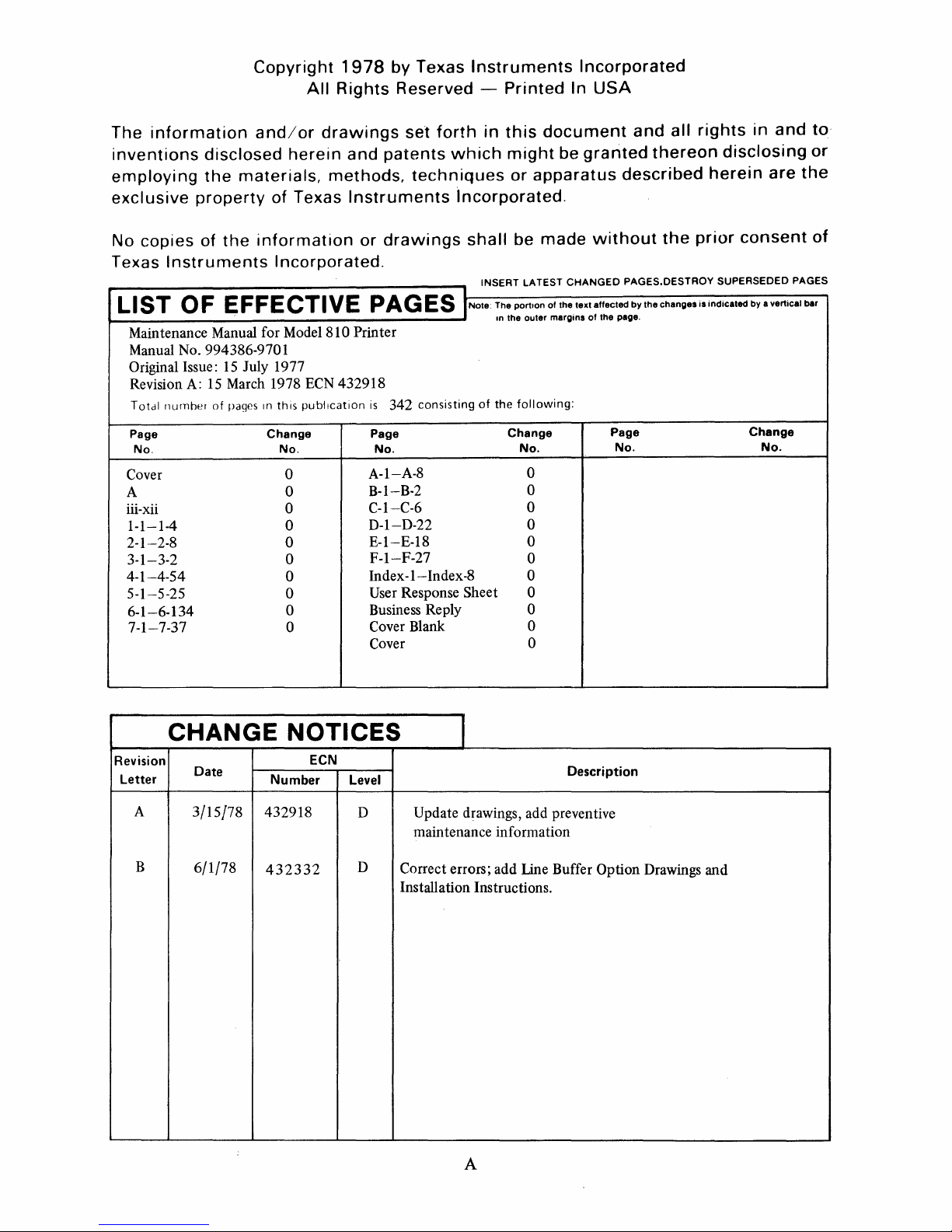
Maintenance Manual for Model 810 Printer
Manual No. 994386-9701
Original Issue:
Revision
T
otdl
nurnher
A:
15
15
March 1978
of
pages
CT
July 1977
In
this
I V
EPA
ECN
432918
publication
G E S I Note: The portIon of the text affected
is
342
consisting
Instruments
Printed
in
this
document
which
might
or
apparatus
incorporated.
shall
be
made
INSERT LATEST
In the outer margins
of
the
following:
Incorporated
In
USA
and
be
granted
described
without
CHANGED
PAGES. DESTROY SUPERSEDED PAGES
by
of
the page.
all
thereon
the
the
changes
rights
in
and
disclosing
herein
prior
is
indicated by a vertical bar
are
consent
to
or
the
of
Page
No.
Cover
A
iii-xii
1-1-1-4
2-1--2-8 0
3-1-3-2
4-1-4-54
5-1-5-25 0
6-1-6-134
7-1-7-37
CHANGE
Revision
Letter
A
B
Date
3/15/78
6/1/78
Change
No.
0
0
0
0
0
0
0
0
NOTICES
ECN
Number
432918
432332
Page
No.
A-I-A-8
B-I-B-2
C-I-C-6
D-I-D-22
E-I-E-18
F-I-F-27
Index
-1-
Response Sheet 0
User
Business Reply
Cover
Blank
Cover
Level
D
D
Correct errors; add Line Buffer Option Drawings and
Installation Instructions.
Change
No.
0
0
0
0
0
0
Index·8 0
0
0
0
I
Description
Update drawings, add preventive
maintenance information
Page
No.
Change
No.
A
Page 3
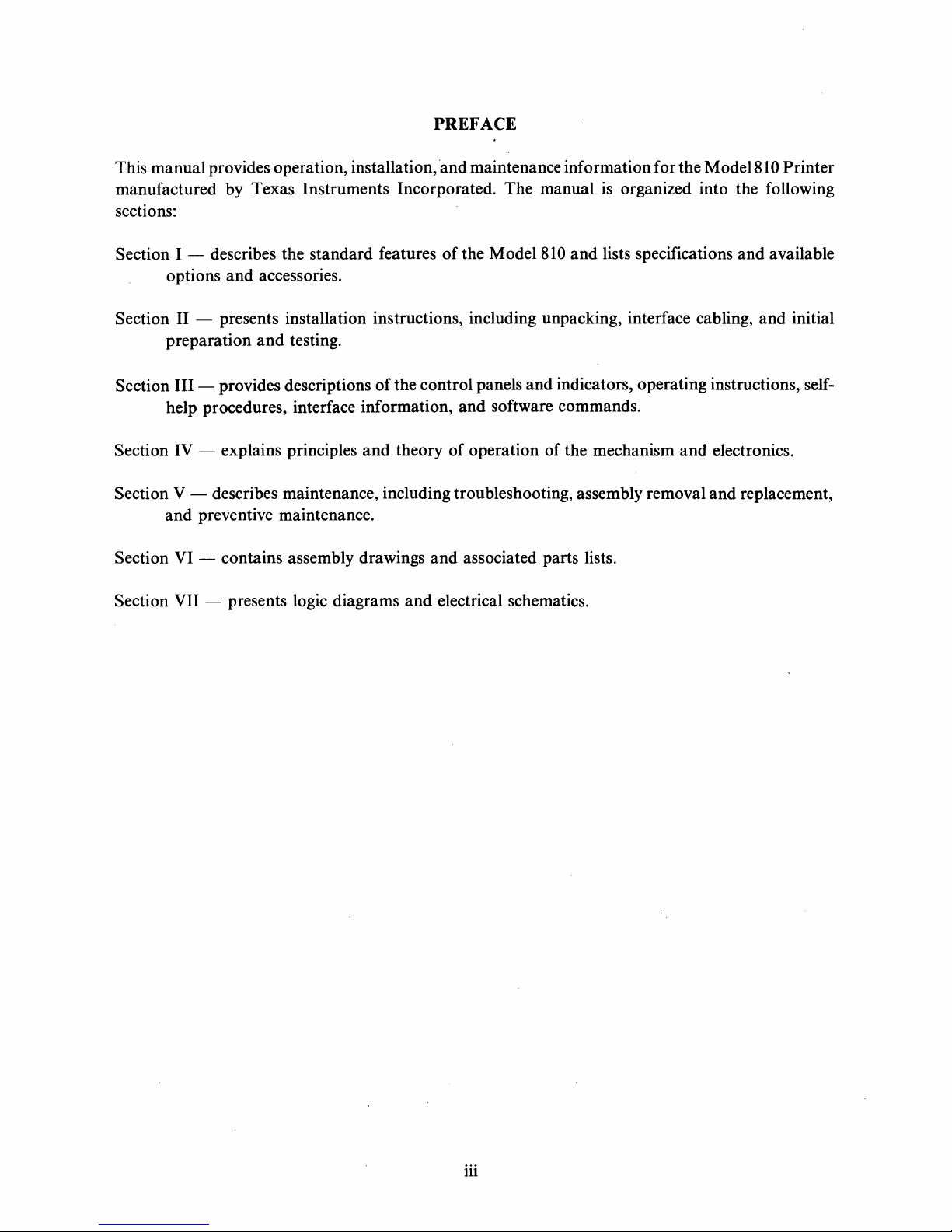
This
manual
manufactured
provides operation, installation, 'and maintenance
by
Texas
sections:
Section I - describes
options
and
accessories.
Instruments
the
standard
PREFACE
Incorporated.
features
of
the
The
Model
information
manual
810
and
for
the
Model81 0 Printer
is organized into the following
lists specifications
and
available
Section II - presents installation instructions, including unpacking, interface cabling,
Section
Section
Section
Section
Section
preparation
III
- provides descriptions
help procedures, interface
IV - explains principles
V - describes maintenance, including troubleshooting, assembly removal
and
preventive maintenance.
VI - contains assembly drawings
VII - presents logic diagrams
and
testing.
of
the
control
information,
and
theory
and
and
electrical schematics.
panels
and
of
operation
and
indicators,
software commands.
of
the
associated parts lists.
operating
mechanism
instructions, self-
and
electronics.
and
replacement,
and
initial
iii
Page 4
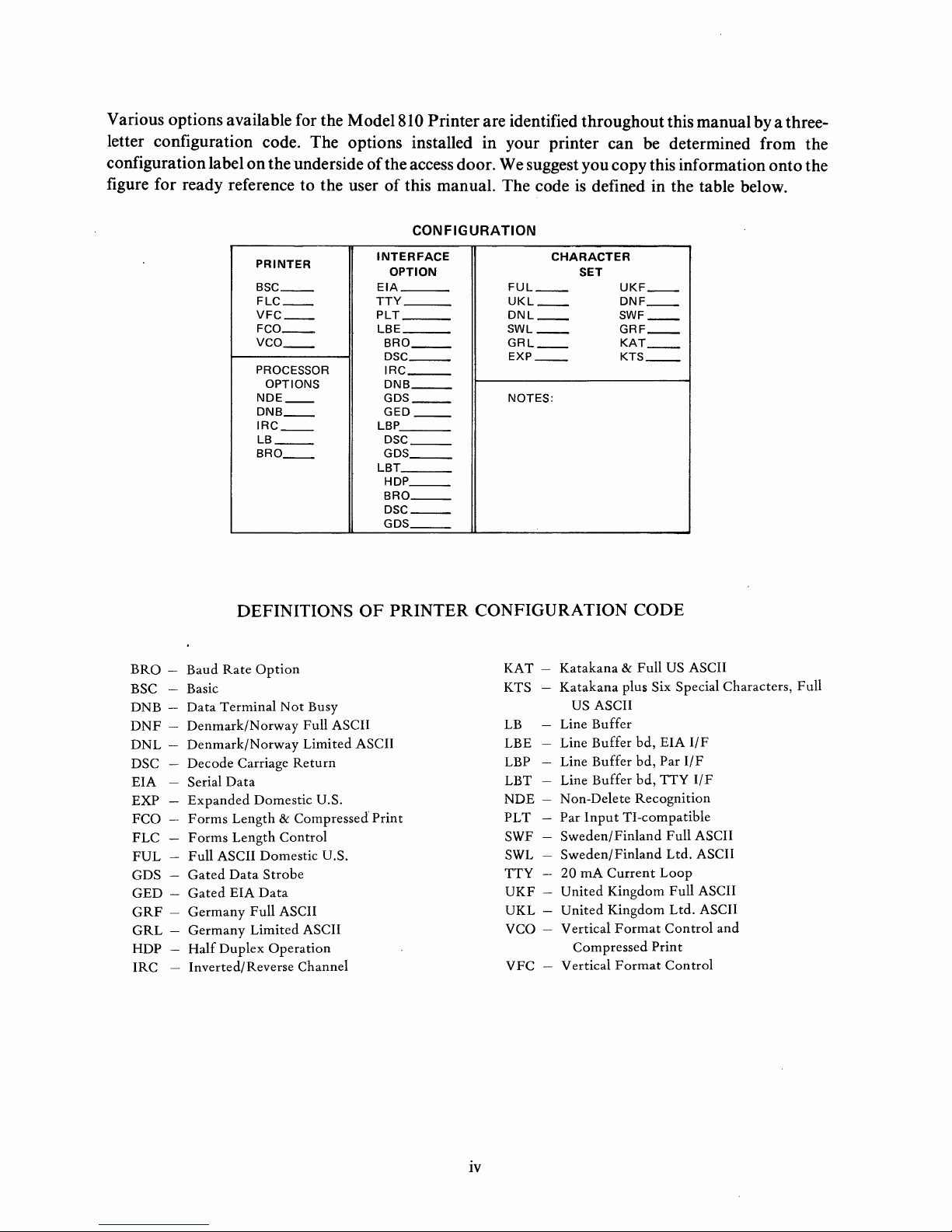
Various options available for the Model 810 Printer are identified throughout this manual by a threeletter configuration code. The options installed in your printer can be determined from the
on
configuration label
the underside
figure for ready reference to the user
PRINTER
__
BSC
FLC
__
VFC
__
FCO
__
VCO
__
PROCESSOR
OPTIONS
NDE
__
DNB
__
IRC
__
LB
__
BRO
__
of
the access door. We suggest you copy this information onto the
of
this manual. The code
is
defined in the table below.
CONFIGURATION
INTERFACE
OPTION
EIA
TTY
___
PLT
LBE
BRO
__
DSC
__
I
RC
___
DNB
__
GDS
__
GED
__
LBP
DSC
__
GDS
__
LBT
HDP
__
BRO
__
DSC
__
GDS
__
FUL
__
UKL
__
DNL
__
SWL
__
GRL
__
EXP
__
NOTES:
CHARACTER
SET
UKF
DNF
SWF
GRF
KAT
KTS
__
__
__
__
__
__
DEFINITIONS
BRa -Baud
-
BSC
DNB DNF -Denmark/Norway
DNL
DSC
EIA
EXP
FCO
FLC
FUL
GDS
GED
-
GRF
-
GRL
-
HDP
-
IRC
Rate
Option
Basic
Data
Terminal
Not
Denmark/Norway
Decode
Serial
Expanded
Forms
Forms
Full
Gated
Gated
Germany
Germany
Half
Carriage
Data
Domestic U.S.
Length & Compressed
Length
Control
ASCII Domestic U.S.
Data
Strobe
EIA
Data
Full
ASCII
Limited
Duplex
Operation
Inverted/Reverse Channel
Busy
Full ASCII
Limited
Return
ASCII
OF
PRINTER
ASCII
Print
CONFIGURATION
KAT KTS
LB
LBE
LBP
LBT
NDE PLT
SWF
SWL
TTY
UKF
UKL
VCO
VFC
Katakana & Full
Katakana
US ASCII
Buffer
Line
Buffer
Line
Line
Buffer
Line Buffer
Non-Delete
Par
Input
Sweden/Finland
Sweden/Finland
20
rnA
Current
United
United
Vertical
-
Kingdom
Kingdom
Format
Compressed
Vertical
-
Format
CODE
US
ASCII
plus Six Special Characters,
bd,
EIA
IfF
bd,
Par
l/F
bd,
TTY
I/F
Recognition
TI-compatible
Full
ASCII
Ltd.
ASCII
Loop
Full
ASCII
Ltd.
ASCII
Control
Print
Control
and
Full
iv
Page 5
TABLE OF CONTENTS
Paragraph Title
SECTION
1.1
1.2 Description
1.3
Introduction . . . . . . . . . . . . . . . . . . . . . . . . . . . . . . . . . . . . . . . . . .
............................................
Configuration
....
1.4 Modification Features
1.5
1.6
Optional Features
Accessories.
. . . . . . . . . . . . . . . . . . . . . . . . . . . . . . . . . . . . . . . . .
I.
GENERAL
'.
. . . . . . . . . . . . . . . . . . . . . . . . . . . . . . . . . . . .
.....................................
........................................
SECTION II. INSTALLATION
2.1
2.2 Space Requirements
2.3 Unpacking and Setting Up
Introduction
............................................
......................................
..................................
2.4 Cabling and Grounding Information
2.4.1 Serial Interface Cable
2.4.2 Parallel Interface Cable
2.4.3 TTY Interface Cable
2.5 Initial Preparation
2.5.1 Line Voltage Selection
2.5.2 Supplies Installation
2.5.3
Operational Checkout
....................................
...................................
.....................................
........................................
...................................
..................................
.................................
DESCRIPTION
............................
Page
..
1-1
1-3
..
1-3
1-3
1-4
..
1-4
2-1
2-1
2-1
2-2
2-3
2-5
2-5
2-6
2-6
2-7/2-8
2-7/2-8
SECTION III.
3.1
Introduction
3.2 Control Panel Controls and Indicators
3.2.1
3.2.2
3.2.3
3.2.4
3.2.5
3.2.6
3.2.7
Paper
Error
On
Out
Indicator
Line Switch and Indicator
Reset/Tab
Form
Align
Form
Align'"
Form
Feed/Set
3.2.8 Line Feed/ Line Feed Switch
OPERATION
AND
INTERFACE
............................................
..........................
Indicator
..............................
........................................
...............................
Switch
./Tab
......................................
/Tab
,Top
Set Switch
Clear Switch
of
Form
.............................
Switch
...........................
..........................
...............................
INFORMATION
'.......
3.2.9 Power Indicator . . . . . . . . . . . . . . . . . . . . . . . . . . . . . . . . . . . . . .
3.3 Auxiliary Control Panel Controls and Indicators
3.3.1
Normal/Test/YFC
Switch (BSC,FLC,VFC,FCO,YCO)
3.3.2 Pencil Switches (BSC,FLC,YFC,FCO,YCO)
3.3.3 8
3.3.4
LPI
Form
Switch and Indicator (BSC,FLC,VFC)
Length
Rotary
Switch (FLC,FCO)
.....................
..............
.....................
.....................
.......................
..
3-1
3-2
3-2
3-2
3-2
3-3
3-3
3-3
3-3
3-3
3-3
3-3
3-5
3-5
3-5
3-5
v
Page 6
TABLE OF CONTENTS (Continued)
Paragraph
3.3.5
3.3.6
3.3.7
3.3.8
3.4
3.4.1
3.4.2
3.4.3
3.4.4
3.4.5
3.4.6
3.4.7
3.4.8
3.4.9
3.4.10
3.4.11
3.4.12
3.4.13
3.4.14
3.4.15
3.4.16
3.4.17
3.4.18
3.4.19
3.5
3.6
3.6.1
3.6.2
3.6.3
3.6.3.1
3.6.3.2
3.7
3.7.1
3.7.2
3.8
3.8.1
3.8.2
3.9
3.9.1
3.9.2
3.9.3
3.9.4
3.9.5 .
3.9.6
3.9.7
Title
VFC Switch (VFC,VCO)
Store/Recall
16.5
CPI/8
Switch (VFC,VCO)
LPI
Switch and Indicators (FCO,VCO)
Elapsed Time Indicator (Optional)
..................................
..............................
................
............................
Operating Procedures . . . . . . . . . . . . . ~ . . . . . . . . . . . . . . . . . . . . . .
Ribbon Installation (All Printers)
Paper
Loading (All Printers)
Turn-On Procedure ( All Printers)
Top
of
Form
Adjustment (All Printers)
Printhead Adjustment (All Printers)
Self-Test Diagnostic (All Printers)
Lines
Per
Inch Spacing (All Printers)
Characters
Baud Rate/ Parallel
Per
Inch Spacing (FCO, V CO)
Input
Selection (All Printers)
Parity Selection (All Printers)
Automatic Line Feed Override (All Printers)
............................
...............................
............................
.......................
..........................
.............
.........................
.....................
.................
..............................
....................
0 • • • • • • • • • • •
Automatic Perforation Skip Override (All Printers) . . . . . . . . . . . . . .
Vertical Tab Setting (All Printers)
Vertical Tab Clearing (All Printers)
Fixed Form Length Selection (FCO, FLC)
Programming
Storing Vertical
Recalling Vertical
Form
Format
Format
Length (FCO, FLC)
(VFC, VFO)
(VFC, VFO)
Turn-Off Procedure (All Printers)
Self-Help Procedures
Serial Interface
Baud Rate
..........................................
.....................................
........................................
...........................
..........................
.....................
......................
.........................
.......................
...........................
Signal Levels and Terminations . . . . . . . . . . . . . . . . . . . . . . . . . . .
Asynchronous
Timing
Parity
Parallel Interface (Optional)
Data
Format
...............................
...........................................
............................................
................................
Signal Levels and Terminations . . . . . . . . . . . . . . . . . . . . . . . . . . .
Timing
TTY Current Loop Interface (Optional)
.............................................
.........................
Signal Levels and Terminations . . . . . . . . . . . . . . . . . . . . . . . . . . .
Timing
Software (Remote Control)
Software Commands
Software
Software Horizontal
Software Line Width Setting
Software Vertical
Software Vertical
Software Vertical
..
. . . . . . . . . . . . . . . . . . . . . . . . . . . . . . . . . . . . . . . . .
.................................
..
. . . . . . . . . . . . . . . . . . . . . . . . . . . . . . . .
Form
Length Setting
Tab
Setting
.............................
............................
..............................
Format
Format
Tab
Recall
Store
Setting
.........
-.
. . . . . . . . . . . . . . . .
............................
..
••
..
0 3-19
..
..
..
..
..
..
Page·
3-5
3-5
3-5
3-6
3-6
3-6
3-7
3-9
3-10
3-11
3-12
3-12
3-13
3-13
3-14
3-14
3-14
3-14
3-15
3-15
3-16
3-16
3-17
3-18
3-18
3-20
3-20
3-21
3-21
3-21
3-21
3-23
3-23
3-23
3-23
3-25
3-25
3-25
3-25
3-29
3-29
3-30
3-30
3-30
vi
Page 7

TABLE
OF
CONTENTS
(Continued)
Paragraph
4.1
4.2
4.2.1
4.2.1.1
4.2.1.2
4.2.1.3
4.2.1.4
4.2.1.5
4.2.2
4.2.3
4.2.4
4.2.4.1
4.2.4.2
4.2.5
4.2.6
4.2.7
4.3
4.3.1
4.3.2
4.3.2.1
4.3.2.2
4.3.2.3
4.3.2.4
4.3.2.5
4.3.3
4.3.3.1
4.3.3.2
4.3.3.3
4.3.4
4.3.4.1
4.3.4.2
4.3.4.3
4.3.4.4
4.3.4.5
4.3.4.6
4.3.4.7
4.3.4.8
4.3.5
4.3.5.1
4.3.5.2
4.3.5.3
Title
SECTION
General
Principles
Dot
...............................................
of
Operation
Matrix
Printhead
Printing Mechanism
Assembly
Carriage Drive
Paper
Ribbon
Dot
Electronic
Firmware
Printhead/
Printhead
Drive
.........................................
Drive
Matrix
Printing
Control
Program
Carriage Subsystem
Drive
Carriage Drive
Paper
Power
Fuses
Theory
Overview
Feed Subsystem
Supply
........................................
..............................................
of
Operation
...........................................
Processor Board
Microprocessor
Communications Interfaces
FIFO
Printhead
Software
Buffer
Carriage
..........................................
IV.
THEORY
OF
OPERATION
....................................
.............................
..................
.......................................
........................................
Mechanics
Subsystem
Overview
............................
...............................
...............................
..............................
......................................
.......................................
..................................
.....................................
......................................
System
................................
..............................
.......................................
Control
..............................
. . . . . . . . . . . . . . . .
Driver Board . . . . . . . . . . . . . . . . . . . . . . . . . . . . . . . . . . . . . . .
Printhead
Carriage
Paper
Power
AC
+ 30 V de Supply
+5
V de Regulator
+8
SW
±12 Vdc
-75
Overvoltage Protection Circuit
Power
Current
Receiver Circuit
Transmitter Circuit
Auxiliary Parallel Interface
Driver Circuits
Motor
Feed
Supply
Power
Driver Circuit
Motor
Driver Circuits
........................................
Module
...................................
.....................................
....................................
...........................................
and
-5
Vdc Regulators
Vdc Supply
Good/Reset
Loop
Option
.....................................
...................................
Board
.....................................
....................................
...............................
............................
.........................
...........................
............................
...............................
'...............................
..
..
Page
4-1
4-1
4-1
4-2
4-2
4-3
4-4
4-4
4-6
4-8
4-8
4-9
4-9
4-11
4-12
4-14
4-14
4-14
4-16
4-16
4-18
4-18
4-18
4-22
4-29
4-29
4-32
4-36
4-42
4-43
4-44
4-44
4-47
4-48
4-49
4-49
4-50
4-52
4-52
4-53
4-53
vii
Page 8
TABLE
OF
CONTENTS (Continued)
Paragraph
5.1
General
SECTION
........................
Title
V.
MAINTENANCE
5.2 Preventive Maintenance 0 0 0 0 • 0 • 0 0 0 0 0 0 0
5.3
5.4 Removal and Replacement . 0 • 0 0
5.4.1
5.4.2 Battery (996351-0001)
5.4.3 AC
5.4.4 Motherboard
5.4.5
5.4.6
5.4.7
5.4.8
5.4.9 Ribbon Drive Assembly (994215)
5.4.10 Control Panel (994251)
5.4.11 Auxiliary Control
5.4.12 Carriage Drive
5.4.13 Wire Rope
5.4.14 Carriage and
5.4.15 Secondary Fuse 0
5.4.16 Power Line Fuse
5.5
5.5.1
5.6 Testing
Troubleshooting 0 0 0 0 0 0 0 • 0 0 0 0 0 0 0 • 0 • 0 • 0
••
0 • 0 • 0 0
Printed Circuit Boards 0 0 0 • 0
....
•• 0 •• 0 ••••
0 0 • 0 0 0 0 0 • 0 0 0 • 0
Power Module (994373-0001) Removal and Replacement
(994330-0001)
Fan
Assembly (996275)
Printhead (994258)
Paper
Paper
Drive
Motor
Tractor (996158-0001, 0002)
..........
Assembly (994183) 0
.............
..........
0"
0 0 0 0 0 • 0 0
0
o.
0"
•••••••
0 0 • 0
0
•••••••••••
•••
0 • 0 0
'0
Panel Assembly (994257) . 0 0
Motor
..
0 0 0 0 0
Paper
Assembly (994238)
•••
0
••••
0
••
0 • • • • • • • • • • • • • • • • • • • • •
Drive Assembly (994183)
•••••••••••
0
•• 0 •••••••••••
................................
Adjustments
Ribbon Guide
.......
............
...............
0
•••
0
••••••••
0
0
•••••
•••
0
0
••••
0
•• 0 ••••••••••••••
0 0 0 • 0 • 0
••
••
0
••
••••
• 0 0 • 0
0.'
......
•••••••
••
0 • 0 0 0 0 • 0
0 0 • 0 • 0
•••
0 • 0 • 0
0
•• 0 •••
0 • • • • • • • • • • • • • • • •
0 • 0
••••
0 • 0
••
0 0 0
0
••••••••••••
••
0
•••••
•••••
0
•••••••
0 0
•• 0 ••
0 0 0 0 0 0 0 0
•••••••••
0 0 • 0 0 • 0
••
0 • 0 • 0 0 • 0 0 0 0 • 0 0 5-14
0 • 0 • 0 • 0 0 • 0 • 0 0 0 0 • 0 5-15
••
0 • 0 • 0 0
0
••
0 • • • • • • • • •
0 • • • • • • • • • • • •
••
0 0 0 0
0 0 0 0 0 0 0 0
0 • 0 0 • 0 0 0 • o.
0
•• 0 ••
0
•••••••
••
••
0 0 0 0
0 • 0 • 0 0 0
..........
••
0 • • • • • •
0 • 0 0 0 0 0 • • •
••
0 0 0 • 0 5-10
0 • 0 0 0 0 0
••••
0 0 0 • 0 5-13
••
0 0 0 0 • 0 5-16
" • • • • • • • •
0 • 0
••
0 • • •
0
••
0 •
o.
o.
0
••
••
••
••
••
••
••
0 5-22
••
••
••
Page
5:-1
5-1
5-1
5-3
5-3
5-5
5-5
5-7
5-8
5-9
5-11
5-18
5-20
5-21
5-24
5-24
5-24
SECTION VI. ASSEMBLY DRAWINGS
SECTION VII. SCHEMATIC DIAGRAMS
APPENDIX
APPENDIX
APPENDIX
APPENDIX
APPENDIX
A.
CHARACTER
B.
ASCII CONTROL
C.
MODEL
OPTIONS,
D.
AND ACCESSORIES
TMS
E.
TMS
810
8080A
5501
AND
PRINTER
MICROPROCESSOR
I/O
APPENDIX F. INSTALLATION OF OPTIONAL KITS
ALPHABETICAL INDEX
viii
AND
LISTS OF MATERIAL
SET
DOT
MATRIX
CHARACTER
VERSIONS,
CONTROLLER
CODE
Page 9
LIST
OF
ILLUSTRATIONS
Figure
I-I Model 810
2-1
2-2
Printer Dimensions
Rear
2-3 Ground
2-4 Cable Options
2-5
3-1
3-2 Control Panel . . . . . . . . . . . . . . . . . . . . . . . . . . . . . . . . . . . . . . . . .
3-3
3-4
3-5
3-6 Asynchronous
3-7
4-1
4-2
4-3
4-4
4-5
4-6
Line Voltage Selection
Control Locations
Auxiliary Control Panels
Ribbon Installation
Paper
Parallel Interface Character Timing
Model 810 Printer Simplified Block Diagram
Model 810 Printer
Printing the Letter
Electronic Control Subsystem Block Diagram
Printhead/ Carriage Subsystem Block Diagram
Carriage
Printer
View
of
Jumper
Loading
Motor
........................................
........•..............................
Printer
Location
_..
.........•............................
...................................
. . . . . . . . . . • . . . . . . . . . • . . . . . . . . • . . . . . . . .
.....................................
........................................
...................................
.......................................
..........................................
Data
Format
Print
head Assembly
"E"
.....................................
Shaft Encoder Phase Relationship for
Left-to-Right Carriage Motion
4-7 Carriage Velocity Profiles Print Mode
4-8
4-9
4-10 Model 810 Printer Simplified Electronics Block Diagram
4-11
4-12
4-13
4-14 Carriage Speed Control Counter Timing Diagram
4-15
4-
16
4-17
4-18
4-19
4-20 Printhead Carriage State Diagram
4-21
4-22 Printhead Solenoid Current Pulse Profile
4-23
4-24
Paper
Drive System Block Diagram
Model 810 Printer Power Supply Block Diagram
Processor
FIFO
Carriage
Forming the Character
PC
Board, Detailed Block Diagram
Memory Write Cycle, Timing Diagram
Motor
Shaft Encoder State Diagram
"W"
Printhead Solenoid Timing Diagram
Normal
Printer Subroutine
Test Mode Flow
Print
Mode Flow Chart . . . . . . . . . . . . . . . . . . . . . . . . . . . .
EI00
Accept States State Diagram
Chart
....................................
Driver Board Block Diagram . . . . . . . . . . . . . . . . . . . . . . . . . . . . . .
Printhead Power Driver Simplified Schematic
Printhead Carriage Driver Simplified Schematic
Title
................................
...........................
......................
..........................
......................
...........
.....•.......................
..........................
...........................
..................
....................
.....................
....................
..................
................................
...........................
..........
:.................
........................
..............
...................
~
.............
...............
. . . . . . .
. . . . .
..
..
..
..
..
..
Page
I-I
2-1
2-2
2-3
2-4
2-5
3-1
3-2
3-4
3-6
3-8
3-21
3-24
4-2
4-3
4-5
4-7
4-9
4-10
4-11
4-12
4-13
4-15
4-17
4-19
4-20
4-21
4-22
4-23
4-24
4-26
4-27
4-27
4-30
4-31
4-32
4-33
ix
Page 10
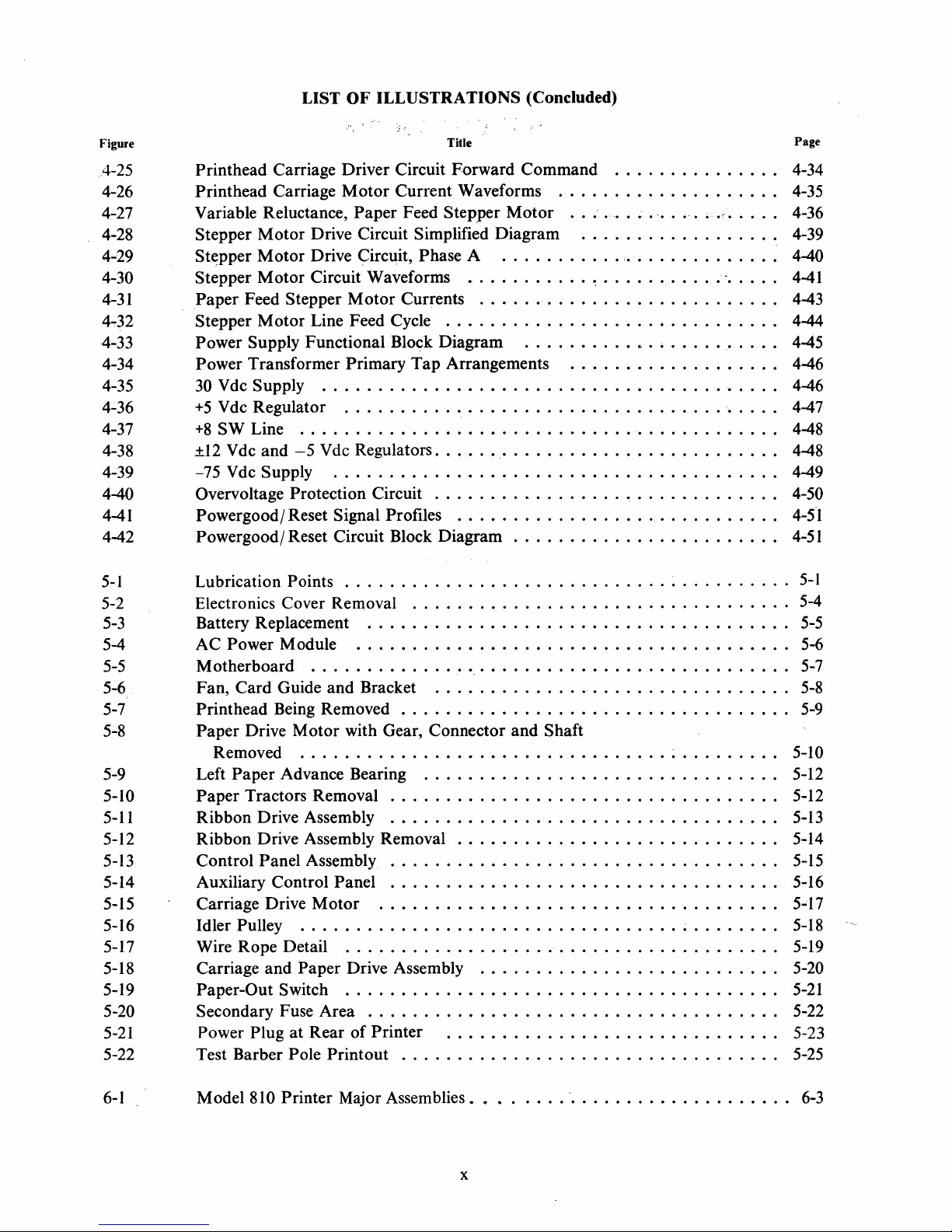
LIST OF ILLUSTRATIONS (Concluded)
Figure Title Page
4-25 Printhead Carriage Driver Circuit Forward Command
4-26
4-27
4-28
4-29
4-30
4-31
4~32
4-33 Power Supply Functional Block Diagram
4-34
4-35
4-36
4-37
4-38 ±12
4-39
4-40 Overvoltage Protection Circuit 0 0
4-41 Powergood/ Reset Signal Profiles 0
Print
head Carriage
Variable Reluctance,
Stepper
St~pper
Stepper
Paper
Stepper
Motor
Motor
Motor
Feed Stepper
Motor
Motor
Current Waveforms
Paper
Drive Circuit Simplified Diagram
Drive Circuit, Phase A 0 0 0 • 0 • 0
Circuit Waveforms
Motor
Line Feed Cycle . 0 0 0 0 0 0 0 • 0 0 0
Power Transformer Primary
30 Vdc Supply
+5
Vdc Regulator
+8
SW Line
Vdc and
-75
Vdc Supply . 0 0 • 0 • 0 • 0 • 0 0
o.
0 0 • 0
...
..
0 0
•• 0 ••
-5
Vdc Regulators
•••
0 0 0 • 0 0 0 0 • 0 0 • 0 0 0 • 0 0 0 0 • 0 0 0 0 • 0 0 0 0
.................
Feed Stepper
Motor
. 0 •
.....
••••
...
0
•••
0 0 • 0 ~ •••••••••••
Currents
Tap
0 0 0 0
0 • 0 0 0 0 0 • 0 • 0 0 0 0 0 0 • 0
................
••
o.
0 • 0 0 0 • 0 0
Arrangements 0 0 • 0 • 0 0 • 0 0
••
..
0
••
••
•••
•••
0 0 0 0 0
00
0 0 0 0 • 0
0 0
••
0 0 • 0 0 0 0 • 0
0 0 0 0 • 0 • 0 • 0 • 0 0 0
••
0 0 0 0 0 0 • 0 0 0 0
...
0 • 0 • 0 • 0 • 0 0 0
0
••
0 • 0 0 0 0
4-42 Powergood/ Reset Circuit Block Diagram 0 0 • 0 0 0 • 0
5-1
5-2 Electronics Cover Removal
5-3
5-4
5-5 Motherboard
5-6
5-7
5-8
Lubrication Points
...............
0
•••
0 0 • 0 • • • • • • • • • • • • • • • • •
................
Battery Replacement . 0 • 0
AC Power Module 0
....
Fan, Card Guide
0
and
Bracket 0 0
•• 0 •••••
••••••
•••
0 • 0
0 0
••••••
0 0
••••
0 0 0 0 0 0 0
•••
0
••
0 0
•••
0 • 0 • 0 0
0
•• 0 •••
•••
0 0
•• 0 •••
0 • 0 0
0 0
Printhead Being Removed 0 • • 0 0 • • • 0 0 0 • • • 0 • 0 0 • • 0 • • • • • 0 0 • • • 0 •
Paper
Drive
Motor
with Gear, Connector and Shaft
Removed . 0 • 0 • 0 • • • 0 • 0 0 0 0 • • 0 0 • 0 • 0 • 0 0 0 0 0 0 0 0 0 0 0 0 0 • 0 • • 0 0 5-10
5-9 Left
5-10
5-11
5-12
5-13 Control Panel Assembly 0
5-14
5-15
5-16 Idler Pulley 0 0 0 0 0 0 0 0 0 0 0 0 • 0
5-17
5-18
5-19 Paper-Out Switch 0 0
5-20 Secondary Fuse Area 0 0 0 • 0 0
5-21
5-22
Paper
Paper
Ribbon Drive Assembly 0 0 0 0 0 0 0
Ribbon Drive Assembly Removal
Auxiliary Control Panel 0
Carriage Drive
Wire Rope Detail
Carriage
Power Plug
Advance Bearing 0 0 0 0
Tractors Removal 0 0 0 0 • 0 0
•••••
•••
0
•••
Motor
and
Paper Drive Assembly 0 0 0
at
Rear
. 0
•••••
o.
00
• • 0 0 • • 0 • 0 0 0 0 • • 0 0 • 0 0 0 0 0 • • 0 0 0 0 0 0 0 • 0 • 0 5-19
••
0 0 • 0
•• 0 ••
••••••
of
Printer . 0 0 0 0 0 0 • 0 0 0
•••
0 • 0 0 0 0 • 0 0 • 0 0 0 0 0 0 0 0 0 0 0 0 0 • 0 5-12
••
0
•••
0 • 0 0 0 0 • 0 0 0 0 0
•••
0 0 • 0 0 0 0 0 0 • 0
o.
0
••
0 • 0 • 0 0 0
0 • 0
••
0 0 • 0 • 0
0 • 0 0 0
0
••
0 0 0 0 0 • 0 0 0 0
•••
0 0 0 • 0 • 0 0 0 0
••
0 0 0 0 0 • 0 0 0 0 0 0 0 0 0 0
0 0 • 0 0 0 0 • 0 0 • 0 0 0 0
••
••••••
0 0 • 0 0 0 0 0 0 0 0 0 0 • 0 0
•• 0 ••••
Test Barber Pole Printout 0 0 0 0 0 0 • 0 0 • 0 0 0 0 0 0 0 • 0 0 0
...............
00
0 ;
.• ' •••
0
•••
" • 0 0
0 0 0 • 0
••
••
•••
0 • 0
•••••
•• 0 ••••••
0 0
0 0 0
••
••••
•••
0
••••••••
••
0,
0
••••
•• 0 .....
0'0
•••••
•••••••
••
0 0 • 0 • 0 • 0 • 0 • 0
0 • 0
•••
•••••••
••••••••
•• 0 ••
•••
0 0
0
••
••
•• 0 ••
•••
0 • 0 • 0 • 0 • •
•••
0 • 0 • • • • •
0 0 • 0 0 • 0 • 0 0 0 0
0 0 0 ~ 0 0 0 0 0 •
••
•••
0
•••
••
0 0 0 0
4-34
0
••
4-35
0 •
oC
0 0 •
••
4-36
0 0
••
0 • 0 0 0 4-39
0 • • • •
0 • 0 • 0 0 0 • 0 4-44
0 0
••••
0 • 0 0 0
••
0 • 0 • 0 0 0
0 • 0 0 0 • 0
•••
".
•••
0 0
0 • 0
• •
••
4-40
••
4-41
0 0 4-43
0 0 4-45
••
0 4-46
0
••
4-46
0 • 0 4-47
••
4-48
0
••
4-48
••
4-49
••
4-50
••
4-51
4-51
5-1
0
•••••••
0
•••
0 • 0 • 0 0
•• 0 ••••
0 • 0 0 • 0
0 • 0 0 0 0 • 0 5-12
0 0 0 • 0 • 0
0 0 • 0 • 0
••••
0 0 0 0 0 0
0 • 0 • 0 0 0 5-22
0 • 0 • 0 •
•••••
0
•••
o.
o.
••
••
o.
o.
o.
o.
o.
o.
0 5-5
••
••
••
5-4
5-6
5-7
5-8
5-9
5-13
5-14
5-15
5-16
5-17
5-18
5-20
5-21
5-23
5-25
6-1
Model 810 Printer Major Assemblies
.•...
x
0 0 0
-.
0 0 0 0 0
••
0 0 0 0
••
0 0 0 0 • 0
6-3
Page 11
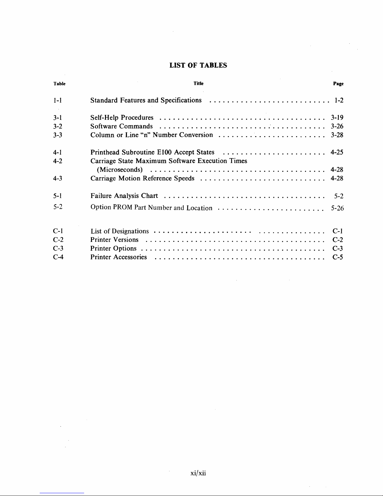
LIST OF TABLES
Table
I-I
Standard
Features
and
3-1 Self-Help Procedures
3-2 Software
3-3
4-1
4-2
Column
Printhead
Carriage
Commands
or
Line
'~n"
Subroutine
State
Maximum
(Microseconds)
4-3
5-1
5-2
C-l
C-2
C-3
C-4
Carriage
Failure Analysis
Option
List
Printer
Printer
Printer
Motion
Reference Speeds
Chart
PROM Part
of
Designations
Versions
Number
.......................................
Options . . . . . . . . . . . . . . . . . . . . . . . . . . . . . . . . . . . . . . . . .
Accessories
Title
Specifications 1-2
.....................................
......................................
Number
EI00
Conversion
Accept States
.........................
......................
Software Execution Times
.......................................
...........................
...................................
and Location
......................
. . . . . . . . . . . . . . . . . . . . . . . .
.
.............
.....................................
.
.
.
.
.
.
.
Page
3-19
3-26
3-28
4-25
4-28
4-28
5-2
5-26
C-I
C-2
C-3
C-5
xi/xii
Page 12

Page 13
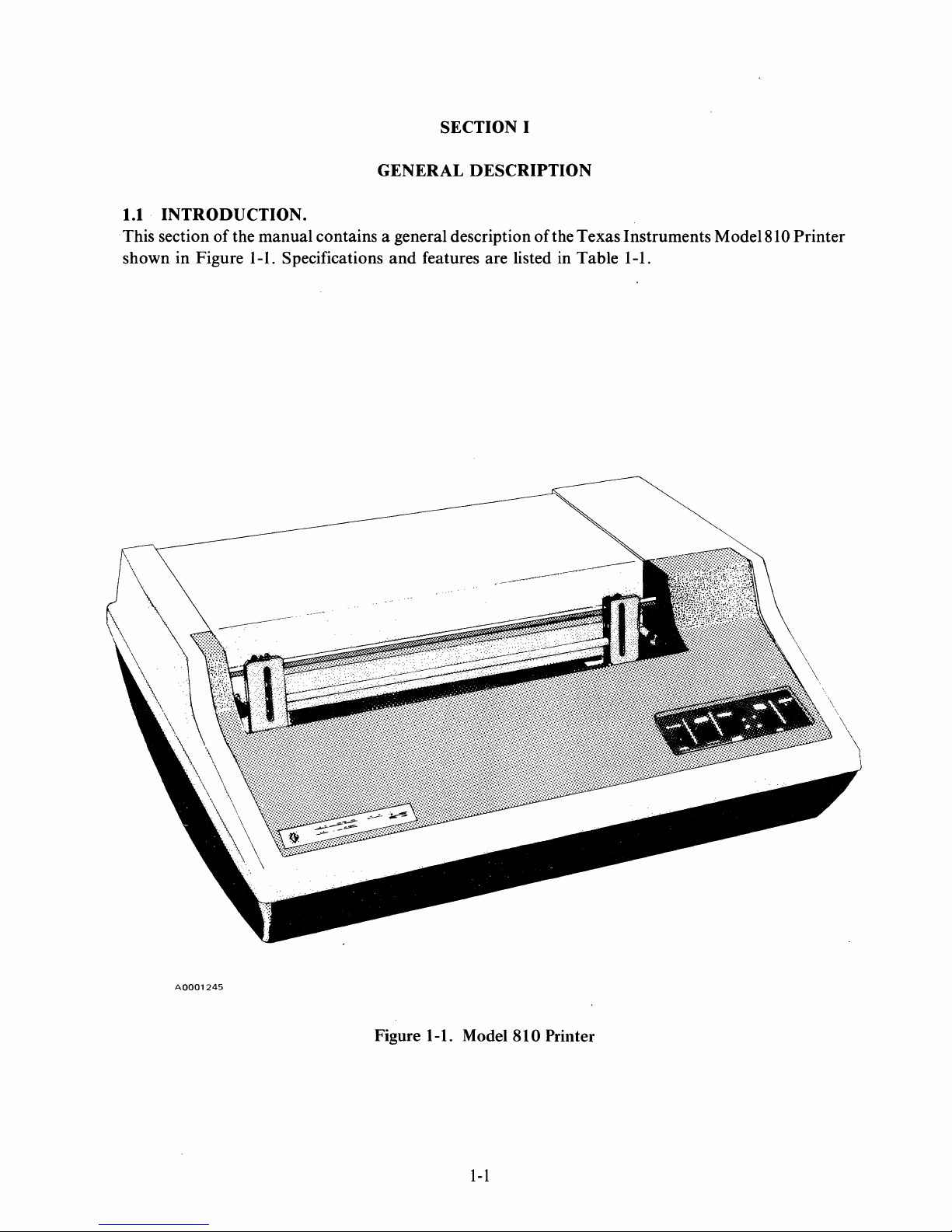
SECTION I
1.1
INTRODUCTION
. This section
of
shown in Figure
GENERAL
DESCRIPTION
.
the manual contains a general description
1-1.
Specifications and features are listed in Table 1-1.
of
the Texas Instruments Model81 0 Printer
A0001245
Figure 1-1. Model
1-1
810
Printer
Page 14
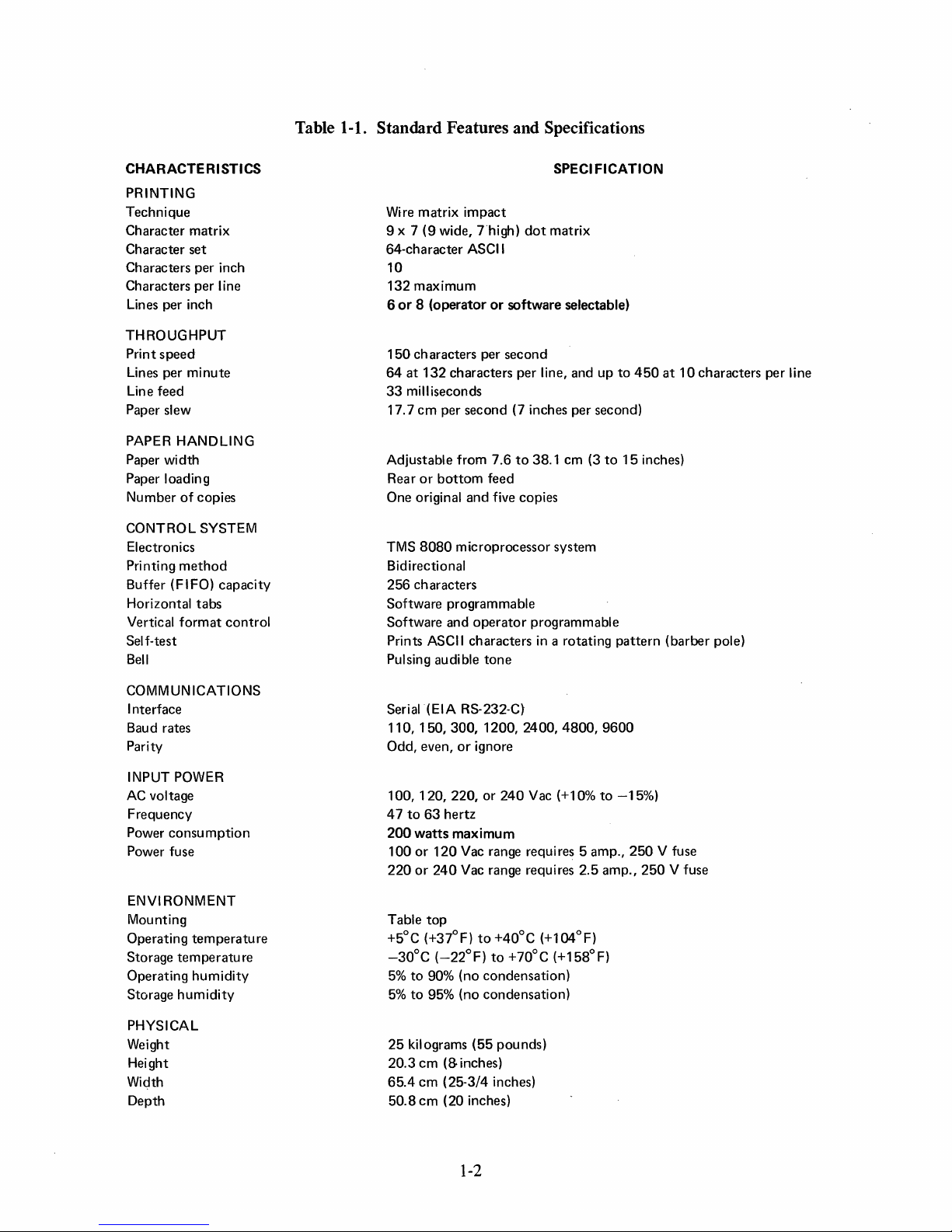
Table 1-1. Standard Features and Specifications
CHARACTERISTICS
PRINTING
Technique
Character matrix
Character set
Characters per inch
Characters per line
Lines per inch
THROUGHPUT
Print
speed
Lines per
Line feed
Paper slew
PAPER HANDLING
Paper width
Paper loading
Number
CONTROL SYSTEM
Electronics
Printing
Buffer (FIFO) capacity
Horizontal
Vertical
Self-test
Bell
minute
of
copies
method
tabs
format
control
SPECI
FICATION
Wire matrix
9 x 7
64-character ASCII
10
132
maximum
6
or 8 (operator
150
characters per
64
at
33
milliseconds
17.7
Adjustable from 7.6
Rear
One original
TMS
Bidirectional
256 characters
Software programmable
Software and
Prints ASCII characters in a rotating
Pulsing audible
impact
(9
wide,
Thigh)
132
characters per line, and up
cm
per second (7 inches per second)
or
bottom
and
8080
microprocessor system
operator
dot
matrix
or
software selectable)
second
to
38.1 cm (3
feed
five copies
programmable
tone
to
to
15
pattern
450
at
inches)
(barber pole)
10
characters per
Hne
COMMUNICATIONS
Interface
Baud rates
Parity
INPUT POWER
AC
voltage
Frequency
Power
consumption
Power fuse
ENVI RONMENT
Mounting
Operating
Storage
Operating
Storage
PHYSICAL
Weight
Height
Width
Depth
temperature
tem
peratu
humidity
humidity
re
Serial (EIA R5-232-C)
110,150,300,1200,2400,4800,9600
Odd, even,
100,120,220,
47
to
200
100
220
Table
+5°C (+37°F)
-30°C
5%
to
5%
to
25
kilograms
20.3
65.4
50.8
or
ignore
or
240
Vac (+10%
63
hertz
watts
maximum
or
120
Vac range requ ires 5 amp.,
or
240
Vac range requires 2.5 amp.,
top
to
+40°C
(-22°F)
90% (no condensation)
95% (no condensation)
cm
(8
cm
(25-3/4 inches)
cm
(20 inches)
to
(55
inches)
+70°C (+158°F)
pounds)
(+l04°F)
to
-15%)
250
250
V fuse
V fuse
1-2
Page 15
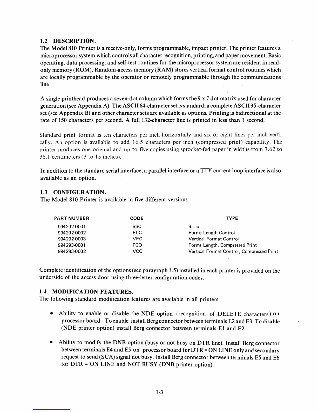
1.2
DESCRIPTION.
The Model 810 Printer
is
a receive-only, forms programmable, impact printer. The printer features a
microprocessor system which controls all character recognition, printing, and paper movement. Basic
operating,
data
processing,
and
self-test routines for the microprocessor system are resident in read-
only memory (ROM). Random-access memory (RAM) stores vertical format control routines which
or
are locally programmable by the operator
remotely programmable through the communications
line.
dot
A single printhead produces a seven-dot column which forms the 9 x 7
A).
generation (see Appendix
B)
set (see Appendix
of
150
rate
characters per second. A full 132-character line
and
Standard print format
is
cally. An option
available
printer produces one original and up
38.1 centimeters (3 to
In
addition to the standard serial interface, a parallel interface
available as
an
option.
15
The ASCII 64-character set
other character sets are available
is
ten characters per inch horizontally and six
to
add 16.5 characters per inch (compressed print) capability. The
to
five
copies using sprocket-fed paper in widths from 7.62
inches).
is
standard; a complete ASCII 95-character
as
options. Printing
is
printed in less
or
a TTY current loop interface
matrix used for character
is
bidirectional
than
1 second.
or
eight lines per inch verti-
at
is
the
to
also
1.3
CONFIGURATION.
The Model 810 Printer
PART NUMBER CODE TYPE
994292-0001
994292-0002
994292-0003
994293-0001
994293-0002
Complete identification
underside
1.4
of
the access
MODIFICATION
The following standard modification features are available
• Ability to enable or disable the
processor board .
(NDE
printer option) install Berg connector between terminals
• Ability to modify the DNB option (busy
between terminals E4 and
request
for
to
DTR = ON
is
available in five different versions:
BSC
FLC
VFC
FCO
VCO Vertical
of
the options (see paragraph 1.5) installed in each printer
door
using three-letter configuration codes.
Basic
Forms
Vertical
Forms
Length
Length,
FEATURES.
in
all printers:
NDE
option (recognition
To
enable install Berg connector between terminals E2 and E3.
or
not
busy
on
DTR
E5
on
processor
board
for
DTR = ON
send (SCA) signal not busy. Install Berg connector between terminals
LINE
and
NOT BUSY (DNB printec option).
Control
Format
Format
Compressed
of
DELETE
El
Control
Control,
is
and
Print
Compressed
provided on the
characters)
To
disable
E2.
line). Install Berg connector
LINE only and secondary
E5
and
Print
on
E6
1-3
Page 16
• Ability
tween terminals E8 and E9 (on processor board
to
modify the IRC option (reverse channel signal). Connect Berg connector be-
-0002 only) for asserted signal HIGH
(standard). Connect Berg connector between terminals E7 and E8 for asserted signal
(lRC printer).
. • Bell option. Disconnect R99 connection on Power Supply board
1.5 OPTIONAL FEATURES.
The following features (identified
by
configuration code in parentheses) are offered as options:
Full ASCII 95-character set (FUL)
to
disable bell.
LOW
European (DNF, DNL,
Texas Instruments-compatible
TTY
20-mA neutral current loop (TTY)
Selectable forms lengths
SWF,
(FCO
SWL,
UKF, or UKL) and
(PL T)
or
FLC)
Vertical Format Control, non-volatile eight-channel memory
(FCO
Compressed print 16.5 characters per inch
or
Elapsed Time Indicator
Line Buffer
Option Kit (See Appendix F for installation instructions).
1.6 ACCESSORIES.
The following items are available
as
accessories:
Paper Basket
other
VCO)
character sets
(VCO
or
VFC)
Floor Mounting Stand
Interface Cable (See cabling information in Section II for selection
1-4
of
cables.)
Page 17
SECTION
INSTALLATION
2.1
INTRODUCTION.
This section provides information for selecting the installation site, unpacking
printer,
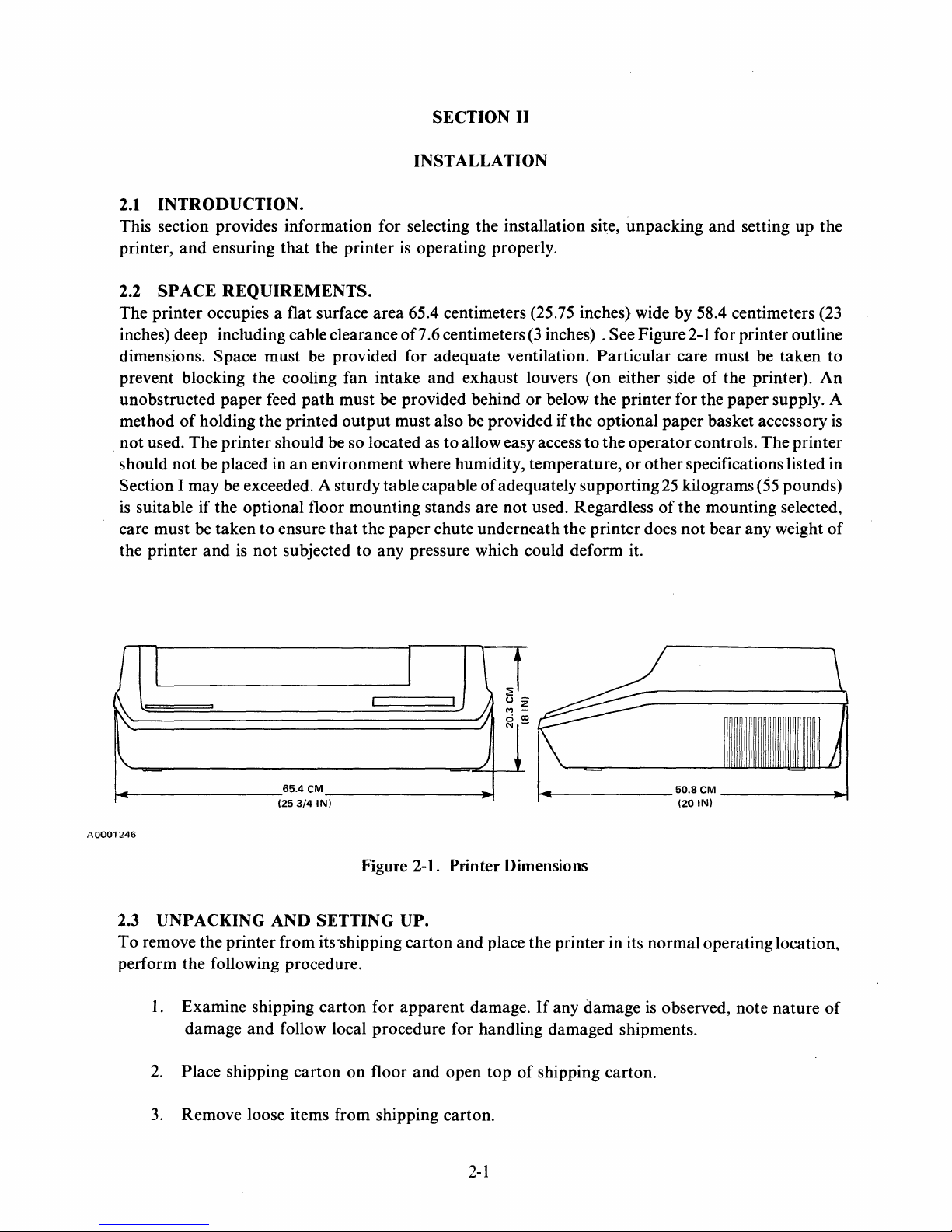
2.2
The printer occupies a flat surface area 65.4 centimeters (25.75 inches) wide by 58.4 centimeters (23
inches) deep including cable clearance of7.6 centimeters
dimensions. Space must be provided for adequate ventilation. Particular care must be taken to
prevent blocking the cooling fan intake and exhaust louvers
unobstructed paper feed
method
not used. The printer should be so located as
should not be placed in
Section I may be exceeded. A sturdy table capable
is
care must be taken
the printer
and
ensuring
SPACE
suitable if the optional floor mounting stands are
REQUIREMENTS.
of
holding the printed output must also be provided if the optional paper basket accessory
and
is
that
the printer
path
must be provided behind
an
environment where humidity, temperature,
to
ensure
not
that
subjected to any pressure which could deform it.
is
operating properly.
to
allow easy access
the paper chute underneath the printer does
II
(3
inches) . See Figure
(on
either side
or
below the printer for the paper supply. A
to
the
of
adequately supporting
not
used. Regardless
and
setting up the
2-1
for printer outline
of
the printer).
operator
or
other specifications listed in
controls. The printer
25
kilograms
of
the mounting selected,
not
bear any weight
(55
pounds)
An
is
of
I
~
65.4
(253/4
A0001246
UNPACKING
2.3
To
remove the printer from its 'shipping carton and place the printer in its normal operating location,
perform the following procedure.
I.
Examine shipping carton for apparent damage.
damage and follow local procedure for handling damaged shipments.
2.
Place shipping carton on floor and open top
3.
Remove loose items from shipping carton.
AND
CM
IN)
Figure 2-1. Printer Dimensions
SETTING
I
I I
UP.
\ J
u-
Z
M -
ci 00
N-
1
)
of
~
______
If
any damage
shipping carton.
50.8
CM
--------I.-t
(20
IN)
is
observed, note nature
of
2-1
Page 18
4. Using
printer
5. Remove styrofoam end caps.
an
assistant, grip printer close
from
shipping carton,
and
to
place
styrofoam end caps
.printer
on
table
or
(at
either end
of
printer), lift
optional floor mounting stand.
6. Remove two mechanism shipping snubbers
7.
Open
access door, remove styrofoam block covering printhead,
wrapped
8. Slide
freely
around
printhead
and
that
printhead.
from stop
wire rope is
to
not
stop
unstrung.
9. Close access door.
10.
(If
applicable) Install optional
AND
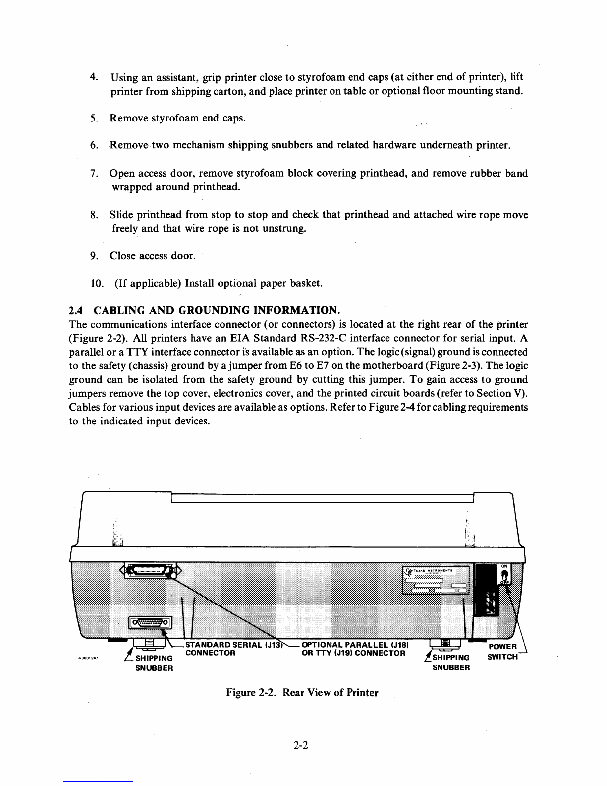
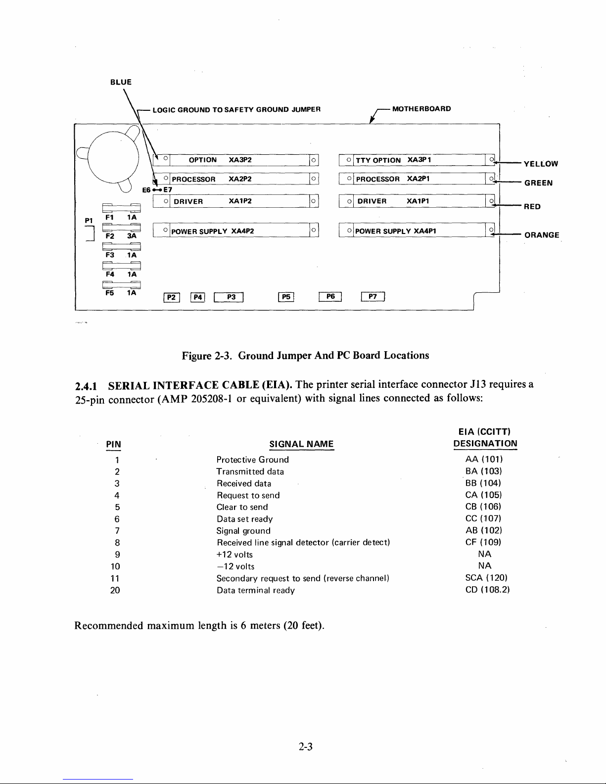
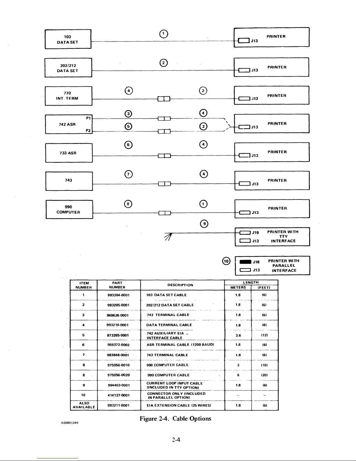
2.4 CABLING
The
communications interface connector
GROUNDING
(Figure 2-2). All printers have
parallel
to
ground
jumpers remove the
Cables for various
to the indicated
or a TTY
interface connector is available as
the safety (chassis) ground by a
can
be isolated from the safety
top
cover, electronics cover,
input
devices are available as options. Refer
input
devices.
an
EIA
jumper
paper
INFORMATION.
(or
Standard
from
ground
and
related hardware underneath printer.
and
remove
and
check
that
printhead
and
attached wire rope move
basket.
connectors) is located
at
the right rear
RS-232-C interface connector for serial input. A
an
option.
E6
to
E7
by cutting this jumper.
and
the printed circuit boards (refer
on
The
logic (signal) ground
the
motherboard
to
Figure 2-4 for cabling requirements
(Figure 2-3).
To
gain access
rubber
of
the printer
is
connected
The
to
ground
to
Section V).
band
logic
SNUBBER
Figure 2-2. Rear View
2-2
of
Printer
SNUBBER
Page 19
BLUE
r
LOGIC
GROUND
TO
SAFETY
GROUND
JUMPER
r=
MOTHERBOARD
b
d
1A
F1
P1
E
]
2.4.1
d
3A
F2
E
d
F3
1A
E d
F4
1A
b
d
1A
F5
SERIAL
25-pin connector
PIN
1
2
3
4
5
6
7 Signal
8
9
10
11
20
OPTION
o PROCESSOR
OjPOWER SUPPLY
[
[!!J
~
XA3P2
XA2P2
XA1P2
XA4P2
~
Figure 2-3. Ground Jumper And
INTERFACE
(AMP
205208-1 or equivalent) with signal lines connected as follows:
CABLE (EIA). The printer serial interface connector
SIGNAL
Protective Grou nd
Transmitted
Received
Request
Clear
Data
set
Received
+12
votts
-12
volts
Secondary
Data terminal ready
data
to
to
send
ready
ground
line signal
data
send
request
101
0
10 I
\01
[![]
~
NAME
detector
to
(carrier detect)
send (reverse channel)
0ITTY
.-----.---------rl---,0t-
OPTION
o I PROCESSOR
01
DRIVER
XA3P1
XA2P1
XA1P1
YELlOW
loT-GREEN
=========================I==~RED
~------------------~I---,~I
[ 0 \ POWER SUPPLY XA4P1
Q[J
PC
Board Locations
Jl3
requires a
ElA
(CCITT)
DESIGNATION
AA
(101)
BA
(103)
BB
(104)
CA (105)
CB
(106)
CC
(107)
AB
(102)
CF (109)
NA
NA
SCA (120)
CD
(108.2)
ORANGE
Recommended maximum length
is
6 meters (20 feet).
2-3
Page 20
103
DATASET
0)
c:::J
PRINTER
J13
I
L
202/212
DATA
770
INT.
742
_____
733
COMPUTER
SET
TERM
ASR
ASR
743
990
0
c::::r
J13
~------------------~[][]------------------~~c::JJ13
o 0
r.;'\
.:!Jr-------\::..J-5----
:1
0
0
[][J------
CIJ
c::r::::J
CTI
CD
3!
---
r.:\
.
__
~_-----'".,'
0
0
0
0
~
"
L.
___
J1_3
_______
b?J13
c:::J
J13
c::::J
J13
c::::J
J19
c::J
J13
PRINTER
PRINTER
PRINTER
PRINTER
PRINTER
PRINTER
PRINTER
TTY
INTERFACE
~
WITH
ITEM
NUMBER
r--------
2
r-----------------------
3
~------+--------------
4
5
6
7
I-------+_
8
1---------+-----------
8
r---------
9
I---.----+---------------f------------------------r------------
10
I--------+------------f------------------------
ALSO
AVAILABLE
A0001249
PART
NUMBER
993204·0001
-------------
993205-000
969626-0001
993210-0001
---
1
--
-
973265-0001
959372-0002
983848-0001
--------------------
975056-0010
975056-0020
--------------1--------------
994403-0001
414127-0001
993211-0001
-
t-----------------
f-----------------
r----------
Figure 2-4. Cable Options
103
DATA
202/212
DATA
742
TERMINAL
DATA
TERMINAL
742
AUXILIARY
INTERFACE
ASR
TERMINAL
743
TERMINAL
-----------
990 COMPUTER
990
COMPUTER
CURRENT
(INCLUDED
CONNECTOR
IN
PARALLEL
EIA
EXTENSION
DESCRIPTION
SET
CABLE
SET
CABLE
CABLE
CABLE
EIA
CABLE
CABLE
CABLE
----------
CABLE
----------
CABLE
LOOP
INPUT
IN
TTY
OPTION)
ONLY
OPTION)
CABLE
_
(1200
-
------
CABLE
!INCLUDED
(25
WIRES)
BAUD)
------
----------
-
------
J13
~-
-------
--------
------t
-----------
------
(FEET)
(6)
-
(6)
(6)
(6)
(12)
(6)
(6)
(10)
------
(6)
(6)
PRINTER
----
-----
@
_J18
c:::::l
LENGTH
METERS
1.8
1.8
r-------------
1.8
f-----
----------
1.8
3.6
----
1.8
-
----
----
f-------
----
1.8
------
-----r--
3
---
6 (20)
1.8
1.8
WITH
PARALLEL
INTERFACE
2-4
Page 21
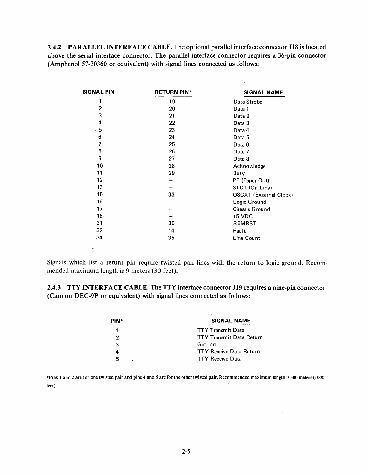
2.4.2 PARALLEL INTERFACE CABLE. The optional parallel interface connector 118
is
located
above the serial interface connector. The parallel interface connector requires a 36-pin connector
(Amphenol
57-30360 or equivalent) with signal lines connected as follows:
SIGNAL
-5
31
32
34
1
2
3
4
6
7
8
9
10
11
12
13
15
16
17
18
PIN
RETURN
19
20
21
22
23
24
25
26
27
28
29
33
30
14
35
PIN*
Signals which list a return pin require twisted pair lines with
is
mended maximum length
9 meters (30 feet).
SIGNAL
Data
Strobe
Data 1
Data 2
Data 3
Data 4
Data 5
Data 6
Data 7
Data 8
Acknowledge
Busy
PE
(Paper Out)
SLCT (On Line)
OSCXT (External Clock)
Logic
Ground
Chassis G rou nd
+5VDC
REMRST
Fault
Line
Count
the
return
NAME
to
logic ground. Recom-
2.4.3 TTY INTERFACE CABLE. The TTY interface connector 119 requires a nine-pin connector
or
(Cannon DEC-9P
*Pins I and 2 are for one twisted pair and pins 4 and 5 are for the other twisted pair. Recommended maximum length
feet).
equivalent) with signal lines connected as follows:
PIN*
2
3
4
5
SIGNAL
TTY
Transmit
TTY
Transmit
Ground
TTY Receive Data
TTY
Receive Data
NAME
Data
Data Return
Return
is
300 meters (1000
2-5
Page 22
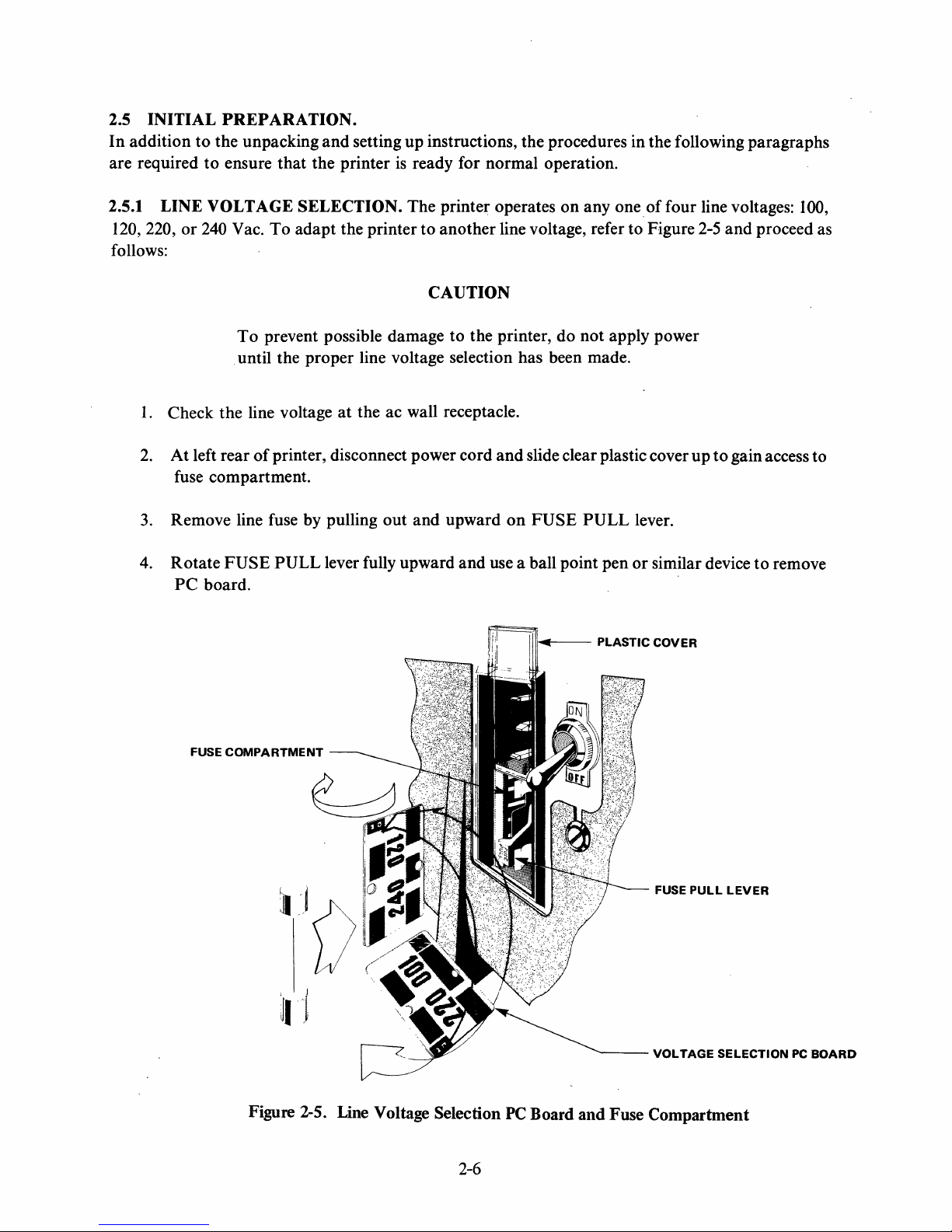
2.5 INITIAL
In
addition
are required
PREPARATION.
to
the unpacking and setting up instructions, the procedures in the following paragraphs
to
ensure that the printer
is
ready for normal operation.
2.5.1 LINE VOLTAGE SELECTION. The printer operates on any one
120, 220,
or
240 Vac.
To
adapt the printer to another line voltage, refer to Figure 2-5
follows:
CAUTION
To
prevent possible damage to the printer, do not apply power
until the proper line voltage selection has been made.
1.
Check the line voltage
2.
At left rear
of
printer, disconnect power cord
at
the ac wall receptacle.
and
slide clear plastic cover
fuse compartment.
3.
Remove line fuse by pulling
4.
Rotate
PC
FUSE
board.
PULL
lever fully upward and use a ball point pen
out
and upward
on
FUSE
PULL
of
four line voltages: 100,
and
up
to
gain access to
lever.
or
similar device
proceed as
to
remove
COMPARTMENT
FUSE
)\),
'~I
III'-f---
PLASTIC
""'----
COVER
FUSE
PULL
VOLTAGE
LEVER
SELECTION
PC
BOARD
Figure 2-5. Line Voltage Selection
2-6
PC
Board and Fuse Compartment
Page 23
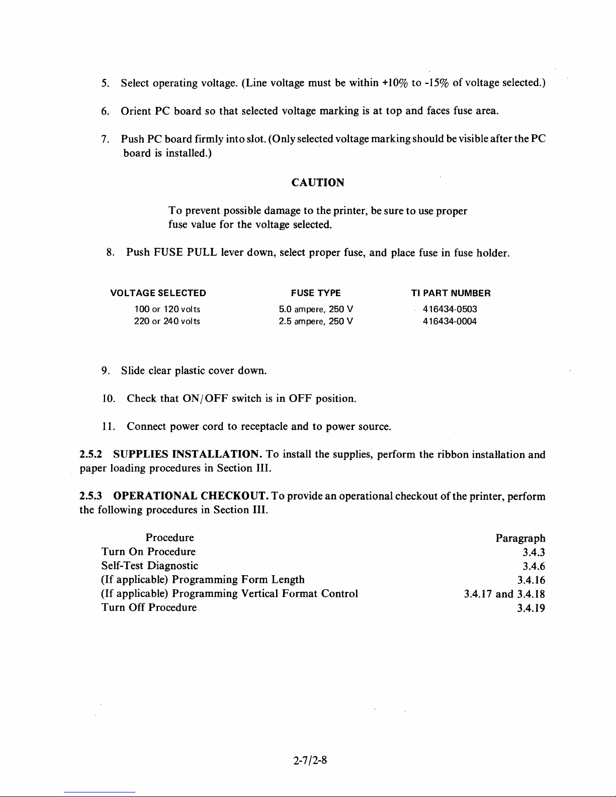
5.
Select operating voltage. (Line voltage must be within
6.
7.
Orient
Push
board
PC
board so
PC
board firmly into slot. (Only selected voltage marking should be visible after the
is
installed.)
that
selected voltage marking
CAUTION
To
prevent possible damage
to
the printer, be sure
fuse value for the voltage selected.
8.
Push
FUSE
PULL
lever down, select proper fuse, and place fuse in fuse holder.
is
+10%
at
to
-15%
of
top
and faces fuse area.
to
use proper
voltage selected.)
PC
VOLTAGE
SELECTED
100 or 120 volts
or 240 volts
220
9. Slide clear plastic cover down.
10.
2.5.2
Check that
11.
Connect power cord to receptacle and
SUPPLIES
ON/OFF
INSTALLATION.
paper loading procedures in
2.5.3
the following procedures in
OPERATIONAL CHECKOUT.
Section III.
Procedure
Turn
On
Procedure
Self-Test Diagnostic
(If
applicable) Programming
(If
applicable) Programming Vertical
Turn
Off Procedure
switch
is
To
Section III.
Form
FUSE TYPE
5.0 ampere, 250 V
ampere, 250 V
2.5
in
OFF
position.
to
power source.
TI
PART NUMBER
416434-0503
416434-0004
install the supplies, perform the ribbon installation and
To
provide
an
operational checkout
of
the printer, perform
Paragraph
Length
Format
Control
3.4.17
and
3.4.16
3.4.18
3.4.19
3.4.3
3.4.6
2-7/2-8
Page 24

Page 25
SECTION
III
OPERATION
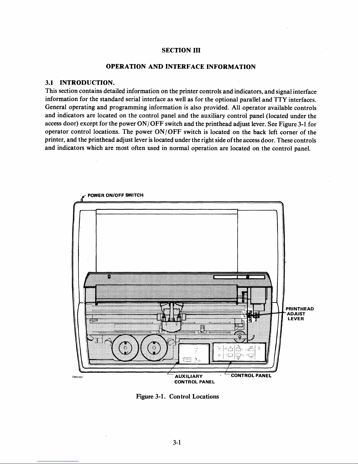
3.1
INTRODUCTION.
This section contains detailed information
AND
INTERFACE
on
INFORMATION
the printer controls
and
indicators,
information for the standard serial interface as well as for the optional parallel
General operating
and
indicators are located
access door) except for the power
operator control locations. The power
printer,
and
and
the printhead adjust lever
indicators which are most often used in normal operation are located
and
programming information is also provided. All operator available controls
on
the control panel
ON/OFF
POWER ON/OFF SWITCH
and
the auxiliary control panel (located under the
switch
ON/OFF
is
located under the right side
and
the print head adjust lever. See Figure
switch is located
on
the back left corner
of
the access door. These controls
on
and
signal interface
and
TTY interfaces.
3-1
of
the control panel.
for
the
COO01253
i.ttttttitit.t~~Si~Itt1~HrPRINTHEAD
E
AUXILIARY
CONTROL
PANEL
Figure 3-1. Con trol Locations
3-1
ADJUST
LEVER
CONTROLPANEL·
Page 26
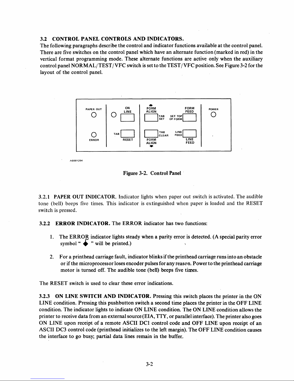
3.2 CONTROL PANEL CONTROLS
The following paragraphs describe the control and indicator functions available
five
There are
switches on the control panel which have an alternate function (marked in red) in
AND
INDICATORS.
at
the control panel.
the
vertical format programming mode. These alternate functions are active only when the auxiliary
control panel
of
layout
the control panel.
NORMAL/TEST
/VFC
switch
is
set to the TEST
/VFC
position. See Figure
3-2
for the
PAPER
0
0
ERROR
OUT
0
TABC]
ON
LINE
C]
RESET
..
FORM
ALIGN
C]TAB
C]TAB
FORM
ALIGN
SET
CLEAR
SET
OF
TOPC]
FORM
LINEC]
FEED
FORM
FEED
LINE
FEED
•
AOOO1254
Figure 3-2. Control
3.2.1 PAPER OUT INDICATOR. Indicator lights when paper out switch
tone (bell) beeps
switch
3.2.2
is
pressed.
ERROR
1.
The
symbol"
five
times. This indicator
INDICATOR. The
ERROR
indicator lights steady when a parity error
ERROR
is
extinguished when paper
indicator has two functions:
• " will be printed.) "
Panel'
is
detected. (A special parity error
POWER
0
is
activated. The audible
is
loaded and the RESET
2.
F or a printhead carriage fault, indicator blinks if the printhead carriage runs into
or
if the microprocessor loses encoder pulses for any reason. Power
is
turned off. The audible tone (bell) beeps five times.
is
used to clear these error indications.
The
RESET switch
3.2.3
ON LINE SWITCH AND INDICATOR. Pressing this switch places the printer in the ON
motor
LINE condition. Pressing this pushbutton switch a second time places the printer in the
condition. The indicator lights
printer to receive data from
ON LINE upon receipt of a remote ASCII
ASCII DC3 control code (printhead initializes to the left margin). The
to
the interface
go busy; partial data lines remain in the buffer.
to
the printhead carriage
to
indicate ON LINE condition. The ON LINE condition allows the
an
external source (EIA, TTY,
DCI
control code and
or
parallel interface). The printer also goes
OFF
LINE upon receipt of an
OFF
LINE condition causes
3-2
an
obstacle
OFF
LINE
Page 27
3.2.4
paper
clearing a carriage fault condition. The alternate TAB function
vertical format control mode. When active, pressing the switch advances the paper
tab
RESET
out
which has been set.
/T
AB
condition
SWITCH.
or
either
The
normal
of
the two error conditions. The printhead moves
RESET
function
of
this pushbutton switch clears the
of
this switch is active only in the
to
the left margin after
to
the next vertical
3.2.5
this pushbutton switch causes the paper
switch
accelerate
function
pushbutton switch sets a vertical
3.2.6
of
paper will continue
The alternate TAB
When active, pressing this pushbutton switch clears the vertical
3.2.7
pushbutton switch causes the paper
printed before paper motion occurs. This switch is active both off line and
TOP
active, pressing this pushbutton switch sets the top
FORM
3.2.8
moved up one line (twelve steps for six lines per inch
buffer
off line. The normal
FORM
is
FORMALIGN
this pushbutton switch causes the paper
FORM
OF
LENGTH
LINE
is
not
ALIGN
held down, three small steps will be taken
paper
of
FORM
movement. This switch is active
this switch
FEED/SET
function
FEED/LINE
empty, its contents will be printed before paper motion occurs. This switch
..
/TAB
is
active only in the vertical format control mode. When active, pressing this
..
/TABCLEARSWITCH.ThenormalFORMALIGN
to
move in 0.014 inch increments. This switch
CLEAR
switch setting.
and
function
TOP
of
this switch
FEED
alternate functions
SET
SWITCH.
to
move up 0.014 inches (refer
tab
at
the present line.
to
of
this switch is active only in the vertical format control mode.
OF
FORM
to
move to the top
SWITCH.
SWITCH.
is
active only in the vertical format control mode. When
Each time this pushbutton switch is pressed, the
of
The normal
and
both
off line
move 0.014 inches down.
The normal
of
the next form. Contents
of
form
and
nine steps for eight lines per inch).
this switch are the same.
FORM
then full line feeds will be executed
and
on
line. The alternate TAB
is
active both off line
tab
at
FORM
or
causes the microprocessor
ALIGN
to
paragraph 4.2.5).
If
the switch
the present line.
on
line. The alternate
..
..
is
FEED
function
of
the line buffer are
is
function
If
the
SET
function
held down,
and
on
line.
of
this
SET
to
read the
paper
If
the line
active'only
of
to
3.2.9
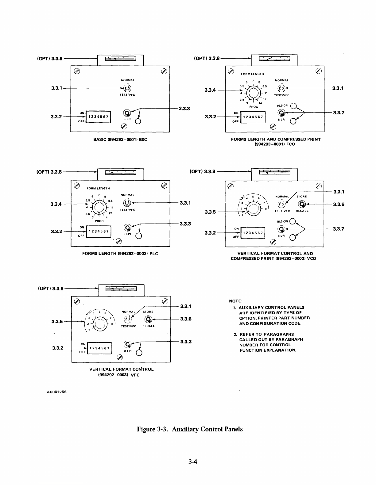
3.3
There are five versions
These are illustrated
indic~tor
configuration code
POWER
AUXILIARY
Basic
Forms Length Control
Vertical Format Control
Forms Length and Compressed
Vertical Format Control and Compressed Print
functions. The letters in parentheses after the name
INDICATOR.
CONTROL
of
the auxiliary control panel:
Panel Type
and
identified in Figure 3-3. The following paragraphs describe the control
of
the control panels shown in Figure 3-3. -
The
POWER
PANEL
Print
indicator lights when the 5 volt supply comes up.
CONTROLS
AND
INDICATORS.
Configuration Code
BSC
FLC
VFC
Fca
VCo
of
the control
3-3
or
indicator refer
to
and
the
Page 28
(OPT) 3.3.S
3.3.1
3.3.2
-----tl§~~§§§l
NORMAL
-+--------~~
_+--O-:N"J
1 2 3 4 5 6
BASIC
TESTIVFC
71
(994292-0001)
BSC
3.3.3
(OPT) 3.3.S
3.3.4
3.3.2
0
FORM
LENGTH
6 7 . 8
"~.'
4
3.5
3
PROG
0::
11
2
34
5 6
FORMS
LENGTH
(994293-0001)
14
NORMAL
,------+--3.3.1
cQ)
11
TESTIVFC
12
(OJ'~----7----+-
71
0
AND
COMPRESSED
FCO
3.3.7
PRINT
(OPT) 3.3.S
0
3.3.4
3.3.2
~
FORM
LENGTH
7
6
8
"~.'
4
3.5
ON
OFF
3
PROG
11
12
14
NORMAL
~
TESTIVFC
-------+-
-------+--
0
3.3.1
3.3.3
'0
FORMS
LENGTH
(OPT) 3.3.S
-----II§§~~~§)l
.:"v.v~
3.3.5--;-~(~~'.\
ON
3.3.2
-+-----l~
OFF
r------,
L--
__
--'
(994292-0002)
TESTIVFC
RECALL
.~....-----+-
He
,;-----+--
loJ~--+--
3.3.1
3.3.6
3.3.3
(OPT) 3.3.S
3.3.5
3.3.2
-----r~ES±i~~±2J~~l
NORMAL
_+-
__
~:~:10~
~
_-+---O-:N"
11
2 3 4 5 6
F
VERTICAL
COMPRESSED
NOTE:
1.
AUXILIARY
ARE
IDENTIFIED
OPTION,
AND
CONFIGURATION
2.
REFER
CALLED
NUMBER
FUNCTION
TO
TESTIVFC
71
FORMAT
PRINT
(994293-0002)
CONTROL
PRINTER
BY
PARAGRAPHS
OUT
BY
PARAGRAPH
FOR
CONTROL
EXPLANATION.
r------1--
STORE
~..---+--
RECALL
R.r.--'*---+--3.3.7
CONTROL
TYPE
PART
AND
VCO
PANELS
OF
NUMBER
CODE.
3.3.1
3.3.6
VERTICAL
A0001255
FORMAT
(994292-0003)
CONTROL
VFC
Figure 3-3. Auxiliary Control Panels
3-4
Page 29
3.3.1
NORMAL/TEST
/VFC
SWITCH
(BSC,
FLC,
VFC,
FCO,
this switch enables normal operation of the printer. With this switch in
II F mode selected, pressing the
pole). With this switch in the
function switches TAB, TAB
ON
LINE switch will initiate a rotating character test
TEST
IVFC
SET, TAB CLEAR, SET
position (and the printer
TOP
OF
enabled for vertical format control programming.
VCO).
In
NORMAL
TEST / VFC
is
OFF
LINE), the alternate
FORM
and LINE
position,
position
and
pattem(barber
FEED
serial
are
PENCIL SWITCHES (BSC, FLC, VFC, FCO, VCO). All auxiliary control panels
3.3.2
1,
pencil switches. Switches
or
4800,
9600 baud
or
2, and 3 are used
parallel input. Switches 4 and 5 are used
to
select baud rates
of
110, 150, 300, 1200, 2400,
to
select odd, even,
parity. Switch 6 activates the automatic line feed. Switch 7 activates the
perforation skip. The automatic perforation skip causes the printer
of
ing the first line
is
off
line.
3.3.3 8
LPI
the next form. Changes in pencil switch settings take effect while the printer
SWITCH
AND
INDICATOR
(BSC, FLC, VFC).
to
skip three lines before print-
In
the 8
top
of
LPI
-have
seven
or
ignore
form automatic
position, this
momentary three-position, center-off switch selects the eight lines per inch mode. This mode is also
software programmable through the communications interface. This indicator lights when the printer
is
in the eight lines per inch mode. Reactivating this switch returns the printer
to
the six lines per inch
mode.
3.3.4
FORM
rotary switch allows the operator
6,
7, 8, 8.5,
form lengths from the front panel from 4
3.3.5 VFC
selects one
LENGTH
11,
12,
and
SWITCH
of
eight non-volatile vertical format programs. These eight channels are also software
ROTARY
14
inches.
to
In
select
the
SWITCH
anyone
PROG
to
112
(FLC, FCO). The 12-position
of
the following J 1 fixed form lengths:
FORM
position, this switch allows the operator
lines.
LENGTH
3,3.5,4,5.5,
to
program
(VFC, VCO). The eight-position vertical format control channel rotary switch
programmable through the communications interface.
3.3.6
STORE/RECALL
SWITCH
position, center-off switch stores manually programmed vertical tabs, form length and lines per inch
spacing in the selected VFC channel.
is
selected VFC channel
recalled into working memory. STORE
vertical format control mode
interface.
3.3.7 16.5
CPI/8
LPI
SWIT~H
momentary three-position, center-off switch selects the
mode. This mode
is
also software programmable through the communications interface. The 16.5
indicator lights when the printer
position a second time returns the printer
printhead initializes to the left margin each time a change
inch.
In
the 8
LPI
position, this switch selects the eight lines per inch mode.
(VFC, VCO).
In
the
RECALL
and
both
are software programmable through the communications
AND
INDICATORS
is
in the compressed print mode. ,Setting this switch
to
In
the
position, the format program stored in the
(FCO, VCO).
16.5
the standard
is
3-5
STORE
position this momentary, three-
and
RECALL
In
the
characters per inch compressed print
10
characters per inch print mode. The
made between
are active only in the
16.5
CPI
position, this
to
the 16.5
10
and
16.5
characters per
The 8 LPI
indicator lights
CPI
CPI
Page 30
when the printer
the communications interface. Setting this switch
printer
3.3.8
to
the six lines per inch mode.
ELAPSED
is
in the eight lines per inch mode. This mode
to
the 8
TIME
INDICATOR
(OPTIONAL). The optional elapsed time indicator shows
is
also software programmable through
LPI
position a second time returns the
accumulated ribbon motion time to 2000 hours.
3.3.9 BAUD RATE OPTION (BRO). This option
gives
you an additional baud rate family. See
Paragraph 3.4.9.
OPERATING
3.4
PROCEDURES.
Before the printer can be placed in service, the operator must determine the following:
1.
Printer configuration: BSC, FLC, VFC, FCO,
of
underside
the access door,
or
identify the printer from Figure 3-3 by the type
or
VCO. (See the configuration label
control panel installed.)
on
of
auxiliary
the
2. Baud rate
printers only)
3. Parity selection: odd, even,
Perform those procedures in the following paragraphs which apply
your printing requirements. The title
parentheses)
procedures;
or
procedures in paragraph
of
the received serial data,
is
to
to
which it applies.
if the
ERROR
3-5.
be received.
or
ignore.
of
If
the printer does
indicator lights;
or
whether parallel
data
(optional
to
your printer configuration and
on
PLC
orPLT
each paragraph identifies the printer configuration (in
not
perform as indicated in the following
or
if the audible tone (bell)
is
heard, consult the self-help
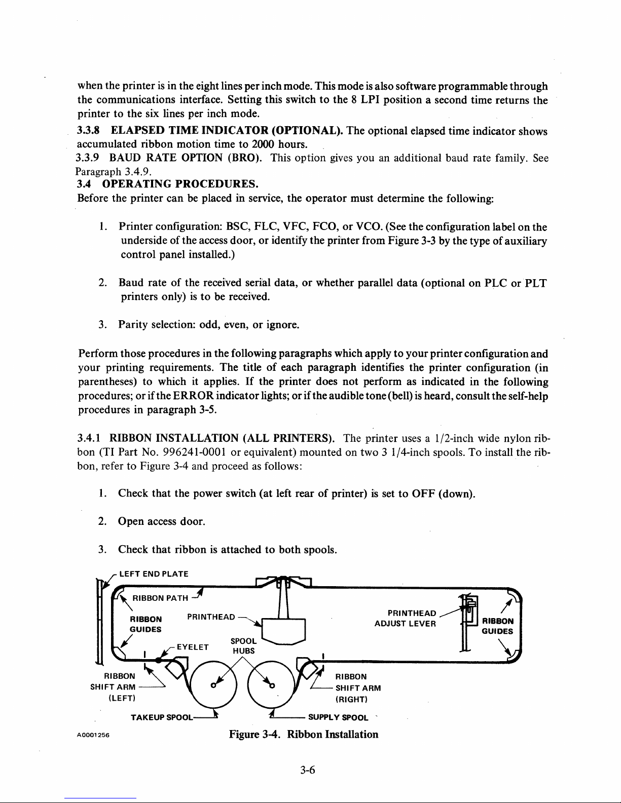
3.4.1 RIBBON INSTALLATION (ALL PRINTERS). The printer uses a 1/2-inch wide nylon ribbon (TI
bon, refer
Part No. 996241-0001 or equivalent) mounted on two 3 1/4-inch spools. To install the rib-
to
Figure 3-4 and proceed
1.
Check that the power switch
2. Open access door.
that
3. Check
LEFT
END PLATE
ribbon
is
attached
as
follows:
(at
to
left rear
both
spools.
of
printer)
is
set
to
OFF
(down).
,RIBBON
A0001256
PATH
PRINTHEAD
~
lJ
RIBBON
LSHIFTARM
(RIGHT)
~--
SUPPLY SPOOL -
Figure 3-4. Ribbon Installation
3-6
PRINTHEAD1
ADJUST LEVER RIBBON
/
GUIDES
\
Page 31

4.
(If
original printhead clearance
Move printhead adjust lever slightly to right and fully toward front
is
to be maintained, note position of printhead adjust lever.)
of
printer (to move
printhead away from platen).
5.
Place empty takeup spool on left spool hub with feed-out side
of
spool toward front of
printer, and feed ribbon out along ribbon path as shown in Figure 3-4.
CAUTION
is
Check that ribbon reversing eyelet
located between the left ribbon
shift arm and the left spool hub (otherwise, the ribbon will not reverse).
is
Also check that the ribbon
on
the ribbon).
6.
Place full supply spool on right spool hub and rotate spool hubs as necessary to remove slack
inside the left end plate (to prevent drag
from ribbon.
7.
Check that ribbon
to Section
8.
If
original printhead clearance
3,
otherwise perform printhead adjustment procedure (paragraph 3.4.5).
V for adjustment.
is
centered in slot on right ribbon shift arm.
is
desired, reset print head adjust lever
If
ribbon
is
not centered, refer
to
position noted in step
3.4.2
PAPER
LOADING (ALL PRINTERS). The printer uses continuous form paper with
standard feed perforations on each edge.
can be accommodated.
forms, one original and up
Using either the rear chute
to
five copies can be printed on paper with the following weight
specifications:
Single
Part Forms:
Multiple Part Forms:
Carbon Paper:
Card stock up to
using the bottom chute.
inch).
To
load paper in the printer, refer to Figure
1.
Open access door.
2.
If
0.1778 millimeter (0.007 inch) thick can be used as single part
In
any case, total form thickness should not exceed 0.533 millimeter (0.021
It
is
not necessary to
left paper feed tractor
is
not locked in desired position (normally
loosen lock knob, adjust left paper feed tractor to
Paper widths from 7.62
or
bottom chute (see Figure 3-5), multiple part
15
to 20 pound
Original:
Copies: 9 to
12
to
12
to
38.1
15
pound
pound, last copy
7-1/2 pound with medium hardness
3-5
and proceed as follows:
NOTE
tum
the power off when loading paper.
des~red
position, and tighten lock knob.
centimeters
or
at
extreme left margin),
(3
to
15
pound
last copy only when
15
inches)
3-7
Page 32

(REAR)
TRACTOR
DOOR
(2
EA.)
PRINTHEAD
ADJUST
LEVER
A0001257
PAPER-OUT
SWITCH
Figure 3-5. Paper Loading
'l
Open doors
Using print head adjust lever, move print head away from platen.
4.
5.
Rear
Chute: Load paper through rear chute as follows
on
both paper feed tractors.
loading):
a. Place paper supply behind printer.
NOTE
If
the printer
on
the floor, be sure the rear edge
over the edge
on
the edge
b. Feed paper (path A, printing side down) into paper chute
paper appears at. platen.
is
mounted on a table
of
the table
of
the table.
top
and
the paper supply is placed
of
the printer is located slightly
to
prevent the paper from catching
(or
proceed
at
bottom
to
Step 6 for
rear
bottom
of
printer until
c.
Proceed
6.
Bottom Chute: Load paper through
to
step
a. Align printer bottom chute with slot in table
7.
bottom
3-8
chute as follows:
or
stand.
Page 33

b. Place paper supply under table
rubbing against table slot
c.
Feed paper
appears
7.
Loosen lock knob
at
platen.
(Path
on
right tractor
B,
width.
8.
Place top
engaged
9.
Close tractor doors. Adjust right
of
paper in
in
corresponding tractor pins.
both
lock knob.
10.
Check
that
11.
that
paper
paper supply
out
switch
is
is
actuated.
Readjust printhead adjust lever
and
align paper
or
ends
of
bottom
printing side forward) into
and
adjust tractor as necessary
tractors
and
tractor
check that holes in paper edge perforations are
as necessary
path
to prevent paper edges from
chute.
bottom
to
chute
remove slack in paper
of
printer until paper
to
accommodate paper
aligned with paper chute (paper must not rub sides
and
close access door.
and
of
chute)
tighten
and
3.4.3 TURN-ON
PROCEDURE
(ALL
PRINTERS).
To
tum
the printer on, proceed as follows:
CAUTION
To
prevent possible damage to the printhead,
without a ribbon
width.
If
the full 132-column line
or
with paper
too
narrow for the printed line
is
used, the paper must be
least 27.8 cm (14-7/8 inches) wide for the standard
per inch spacing
optional
(FCO
and
at
least 21.6 cm (8-1/2 inches) wide for the
and
VCO printers only)
16.5
do
10
characters per inch
compressed print spacing.
1.
Check
that
ribbon and paper are properly installed. (See paragraph 3.4.1 for ribbon
installation and paragraph 3.4.2 for paper loading.)
2. Set power
3.
Observe
At
this point, the printer is operating under the following initial conditions:
ON/OFF
that
control panel ON LINE indicator
switch (at left
rear
of
printer) to
is
off
ON
(up) position.
and
that
not print
at
characters
printhead
is
at left margin.
•
The
printer
is
off line
• The form length is 27.9 cm
printers
if
the auxiliary control panel
(11
inches) for the BSC printer
FORM
LENGTH switch
3-9.
(and
also for the
is
in
the
PROG
FCO
and
FLC
position).
Page 34

The
FCO
and
FLC
switch. The
stored
•
The
VCO and
VCO and
or
recalled.
line spacing
VFC
printers are set to the form length selected
VFC
printers are set
is
16.66
mm
(six lines per inch) for the BSC, FCO,
printers are set
to
the line spacing
to
the form length
of
the last vertical format stored or
on
the
FORM
of
the last vertical format
and
FLC
LENGTH
printers.
The
recalled.
•
The
character spacing
is
2.54
mm
(10 characters per inch) center
to
center.
• All horizontal tabs are cleared from the working memory. (Horizontal tabs can be set only by
software.)
• All vertical tabs are cleared from the working memory
The
VCO
and
VFC printers retain the vertical tab settings
or
recalled.
•
The
line counter
•
The
line buffer
This completes the turn-on procedure
•
From
previous operation, the forms (paper) are aligned as desired and the printhead adjust
is
lever
•
No
properly set.
changes
is
set
to
zero, causing the present line location
is
empty. (All previous printable characters have been cleared.)
if:
to
the above initial conditions are desired.
of
the BSC, FCO,
of
the last vertical format stored
to
be the first line
and
FLC
of
printers.
the form.
• The pencil switches on the auxiliary control panel for the baud rate, parity, automatic line
feed override, and automatic perforation skip override have been previously set as desired.
To
change the printer from its initial condition status, perform the procedures in paragraphs 3.4.4
is
through 3.4.9, as applicable. After all applicable procedures have been completed, the printer
data
to receive
when placed
on
line by the operator
or a DCl
(select) ASCII code character
ready
is
received
via the communications line. All the software commands (described in paragraph 3.9.1) can now be
performed by the sending device (to the degree permitted by the printer options).
3.4.4
set the
top
FORM
of
form as follows: .
To
ADJUSTMENT
prevent possible damage
TOP
OF
without a ribbon
printed line width.
(ALL
PRINTERS).
CAUTION
to
the printhead, do not print
and
do
not
print
on
If
the full 1 32-column line
3-10
With the power
on
paper too narrow for the
is
used, the paper
(paragraph 3.4.3),
Page 35

1.
2.
must be
characters per inch spacing
wide for the optional
at
least 37.8 cm (14-7/8 inches) wide for the standard
and
(FCO
characters per inch compressed print spacing.
Press the
Press the
at
the approximate point where the first line
FORM
FORM
FEED
ALIGN"
switch.
switch
or
NOTE
at
least 21.6 cm (8-1/2 inches)
and VCO printers only) 16.5
the
FORM
ALIGN"
of
the form
switch until the printhead
is
to
be printed.
10
is
A finer
top
of
form adjustment can be made during the self-test
procedure (paragraph 3.4.6),
simply by pressing the
..
switch until the next line printed
FORM
form.
3.4.5
clearance between the platen
accordance with the thickness
PRINTHEAD
ADJUSTMENT
and
the face
of
the forms used. With the power on (paragraph 3.4.3), adjust the
(ALL
PRINTERS).
of
printhead for optimum print quality as follows:
CAUTION
To
prevent possible damage to the printhead,
or
on
without a ribbon
If
width.
the full 132-column line
paper too narrow for the printed line
least 37.8 cm (14-7/8 inches) wide for the standard
per inch spacing
optional
(FCO
and
at
least 21.6 cm (8-1/2 inches) wide for the
and
VCO printers only)
compressed print spacing.
or
while data
ALIGN"
is
is
being received,
or
FORM
exactly aligned
ALIGN
on
the
The printhead adjust lever controls the
the printhead. This clearance must be adjusted in
do
not print
is
used, the paper must be
10
characters
16.5
characters per inch
at
1.
Open the access door.
2.
Move printhead adjust lever slightly
3.
Check that ribbon and paper are installed.
The print head adjustment can be made while the printer
data
and
is
pattern (barber pole)
(If
4.
barber pole method
TEST/VFC.
to
right and completely toward front
NOTE
being printed,
is
used) Set auxiliary control panel
or
while the self-test rotating character
is
being printed.
3-11
is
on
NORMAL/
of
printer.
line
TEST / VFC
switch
to
Page 36

5.
Press control panel ON LINE switch to start printing.
6.
Move printhead adjust lever toward rear of printer until print quality
7.
If
smudging occurs, printhead
8.
Move print head adjust lever until nearest detent
9.
(If
barber pole method has been used) Set auxiliary control panel
switch
10.
to
NORMAL.
Close access door.
is
too close and must be backed off.
is
engaged.
is
satisfactory.
NORMAL/TEST
/VFC
3.4.6
is
SELF-TEST DIAGNOSTIC (ALL PRINTERS). This test will not function if parallel option
selected. With the power on (paragraph 3.4.3), perform the self-test as follows:
CAUTION
To
prevent possible damage to the printhead, do not print
without a ribbon or on paper too narrow for the printed line
If
width.
the full 132-column line
least 37.8 cm (14-7/8 inches) wide for the standard
is
used, the paper must be
10
characters
per inch spacing and at least 21.6 cm (8-1/2 inches) wide for the
optional
(FCO and VCO printers only)
16.5
characters per inch
compressed print spacing.
1.
Open access door.
2.
Ensure pencil switches are
3.
Set auxiliary control panel
4.
Press control panel ON LINE switch and observe that the rotating character pattern (barber
not
set for parallel operation.
NORMAL/TEST
/VFC
switch to TEST /VFC.
pole) starts.
at
5.
Check that the entire 64-character (or optionaI95-character) character set
line, and that each line
6.
After several lines have been printed and checked, set auxiliary control panel
NORMAL/TEST/VFC
3.4.7
..
if the eight lines per inch spacing
LINES
1.
PER
Open access door.
INCH SPACING (ALL PRINTERS). With the power on (paragraph 3.4.3) and
is
shifted one column position from adjacent lines.
switch
is
to
NORMAL and observe that printing halts.
desired, proceed
as
follows:
3-12
is
printed for each
Page 37

2.
Momentarily set auxiliary control panel 8
3.
Observe
4. Close access door.
To
return to the six lines
that
observe
the 8
that 8 LPI
indicator lights.
per
LPI
indicator goes out.
LPI
(or 16.5
CPlj8
LPI)
switch
to
8 LPI.
inch spacing (initial conditions), repeat the above procedure except
3.4.8
and
CHARACTERS
if
the optional 16.5 characters per inch spacing (compressed print)
1.
Open access door.
PER
INCH
SPACING
2. Momentarily set auxiliary control panel 16.5
3.
Observe
4.
Close access door.
To
return to the
observe
that
3.4.9 BAUD
for
PL
T printers), proceed as follows:
1.
Open the access door.
2.
Using a ball point pen
or 3 to
that
16.5
CPI
indicator lights before next line
10
characters per inch spacing (initial conditions), repeat the above procedure except
the 16.5
RATE/PARALLEL
the
CPI
indicator goes
baud
rate
out
INPUT
or
similar device, set the auxiliary control panel "pencil" switches 1,2,
of
the serial
follows:
(FCO,
before the next line
VCO). With the power
is
desired, proceed as follows:
CPlj8
LPI
is
switch
printed.
is
printed.
to
on
16.5
SELECTION. To select the baud rate
data
to
be received,
or
to the optional parallel input as
(paragraph 3.4.3)
CPl.
(or
parallel input
Baud Rate
Standard
110
150 200
300
1200
2400
4800 600
9600 9600
parallel
*BRO = Baud
3.
Close the access door.
Rate
BRO'"
110
300
1200
2400
Option
Pencil
1 2
OFF
ON
OFF
ON
OFF
ON
OFF
ON
3-13
Switches
OFF
OFF
ON
ON
OFF
OFF
ON
ON
3
OFF
OFF
OFF
OFF
ON
ON
ON
ON
Page 38

3.4.10
1.
2.
PARITY
SELECTION (ALL
PRINTERS).
Select parity as follows:
Open the access door.
Set the auxiliary control panel pencil switches 4
and
5 as follows (refer to paragraph 3.3.2):
Pencil Switches
4
ON ON
ON
(ALL
PRINTERS).
Ignore Parity OFF
Odd
Even Parity
3.
Close the access door.
3.4.11
AUTOMATIC
LINE
FEED
auxiliary control panel switch 6
Selection
Parity
OVERRIDE
to
ON
for automatic line feed override
feed. Close the access door.
3.4.12
door
override,
3.4.13
AUTOMATIC
and
set auxiliary control panel switch 7
or
to
OFF
VERTICAL
PERFORATION
for
automatic (three-line) perforation skip. Close the access door.
TAB
SETTING
SKIP
(ALL
OVERRIDE
to
ON for automatic (three-line) perforation skip
PRINTERS).
All printers have a working memory
which vertical tabs can be set and retained as long as the power
3.4.3), set vertical tabs as follows:
1.
If
form
is
not
aligned as desired, perform top
of
form adjustment (paragraph 3.4.4).
5
OFF
OFF
Open the access
or
to
OFF
(ALL
PRINTERS).
is
on. With the power
door
and
for
automatic line
Open the access
on
(paragraph
set
in
2.
Open access door.
3.
Set auxiliary control panel
4.
Press control panel LINE
5.
Press control panel TAB
6.
Repeat steps 4 and 5 as necessary to set all desired tabs.
7.
Set auxiliary control panel
8.
Press control panel
9.
Verify
tab
settings as follows:
FORM
a. Set auxiliary control panel
NORMAL/TEST
FEED
SET
switch until line
switch.
NORMAL/TEST
FEED
switch.
NORMAL/TEST
/VFC
/VFC
3-14
switch
to
be tab-set
switch
/VFC
to
TEST
is
to
NORMAL.
switch to
/VFC.
opposite printhead.
TEST
/VFC.
Page 39

b. Press control panel TAB switch and observe
If
printhead.
CLEAR
c.
Repeat step
desired (tab-set) line
switch (this clears unwanted tabs from working memory).
b.
as necessary
is
not opposite printhead, press control panel TAB
to
verify that only desired tabs are set.
that
desired (tab-set) line
is
opposite
d. After final desired
is
form
e.
Repeat step b. as necessary 'to clear unwanted tabs from working memory.
f.
Set auxiliary control panel
10.
Close access door.
aligned as desired in step
3.4.14 VERTICAL TAB CLEARING (ALL
tab
is
verified, press control panel TAB switch and observe
1.
NORMAL/TESTjVFC
PRINTERS).
switch to
NORMAL.
All printers have a working memory in
that
next
which vertical tabs can be set (paragraph 3.4.13) and retained as long as the power is on. With the
power on (paragraph 3.4.3), these tabs can be cleared as follows:
1.
Press
FORM
Open access door.
2.
3.
Set auxiliary control panel
FEED
switch.
NORMALjTEST/VFC
switch
to
TEST/VFC.
4. Press control panel TAB switch.
5.
If
tab
at
this line location
is
to
be cleared, press control panel TAB
CLEAR
switch; if not,
press control panel TAB switch.
6.
Repeat step 5 as necessary
7. When top
switch to
of
the next form
NORMAL.
to
clear all unwanted tabs.
is
reached, set auxiliary control panel
NORMAL/TEST
jVFC
8. Close access door.
For
the BSC, FCO, and
FLC
printers, all vertical tabs can
be
simultaneously cleared by turning the
power off (paragraph 3.4.19). This returns these printers to the initial conditions listed in paragraph
3.4.3 when the power
3.4.15
FIXED
operator can select
form length (whether set by the operator
(pan~.graph
3.4.3), select a fixed form length as follows:
is
FORM
anyone
again turned on.
LENGTH
of
SELECTION (FCO, FLC). On the
11
fixed form lengths. Selecting a fixed form length clears any previous
FCO
and
FLC
printers the
or
by software) from the working memory. With power on
3-15
Page 40

1.
If
the form
2.
Open access door.
is
not aligned as desired, perform top
of
form adjustment (paragraph 3.4.4).
3. Set auxiliary control panel
4.
Set auxiliary control panel
NORMAL/TEST
FORM
LENGTH rotary switch to desired fixed form length
position.
SET
TOP
OF
5. Press control panel
6.
3.4.16
Set auxiliary control panel
7.
Close access door.
PROGRAMMING
FORM
NORMAL/TEST/VFC
LENGTH
operator can program any form length from 4
FORM
to
previous form length (whether set by the operator
on
power
(paragraph 3.4.3), program the form length as follows:
1.
If
form
is
not aligned as desired, perform
2.
Open access door.
/VFC
switch
to
TEST
/VFC.
switch.
switch to NORMAL.
(FCO,
112 lines. Programming the form length clears any
or
FLC).
On
the
FCO
and
FLC
printers, the
by software) from the working memory. With the
top
of
form adjustment (paragraph 3.4.4).
3.
Set auxiliary control panel NORMAL/TEST /VFC switch
4.
Set auxiliary control panel
5.
Press control panel SET
6.
Press control panel LINE
7.
Press control panel
8.
Set auxiliary control panel
SET
FORM
TOP
FEED
TOP
LENGTH rotary switch
OF
FORM
switch until next form
OF
FORM
NORMAL/TEST
switch. (This sets the line counter
switch.
/VFC
to
TEST /VFC.
to
PROG.
is
aligned as desired.
switch
to
NORMAL. (This sets the
to
zero).
form length.)
9.
Close access door.
3.4.17
vertical format control which can store a different vertical format
memory. Vertical formats can be stored by the operator
information which can
STORING
VERTICAL
be
stored consists
FORMAT
of
(VFC, VCO). The
VFCand
in
each channel
or
by software.
the form length, the vertical
VCOprintershaveaspecial
of
an
eight-channel
The
vertical format
tab
locations,
and
the lines
per inch spacing. The stored vertical formats are retained even with the printer power off. With the
power
(paragraph 3.4.3), a vertical format
is
first entered into working memory and then stored as
on
follows:
3-16
Page 41

1.
If
form
is
not aligned as desired, perform
2.
Open access door.
3.
Set auxiliary control panel VFC rotary switch
4.
Set auxiliary control panel
5.
If
eight lines per inch spacing
16.5
CPI/8
6.
Press control panel
7.
Press control panel LINE
8.
Press control panel TAB
9.
Repeat steps 7 and 8 as necessary to set all desired tabs.
10.
Press control panel LINE
perforation
LPI) switch to 8
SET
is
at
reference mark).
NORMAL/TEST/VFC
is
desired, momentarily set auxiliary control panel 8
LPI
and observe that 8
TOP
OF
FORM
FEED
SET
switch until line to be tab-set is opposite printhead.
switch.
FEED
switch until next form
top
of
switch. (This sets the line counter
form adjustment (paragraph 3.4.4).
to
desired channel position.
switch
to
TEST/VFC.
LPI
indicator lights.
to
is
aligned as desired
LPI
zero.)
(or
paper
(or
11.
Press control panel SET
12.
Set auxiliary control panel switch
13.
Verify vertical format as follows:
TOP
OF
FORM
toNORMAL
a. Press control panel TAB switch and observe
If
printhead.
CLEAR
b. Repeat step a. as necessary
c.
After final desired
observe
desired (tab-set) line is not
switch. (This clears unwanted tabs from memory.)
to
verify that only desired
tab
has been verified, again press control panel TAB switch and
that
perforation
of
next form
TAB CLEAR.
c.
d. Repeat step
14.
Momentarily set auxiliary control panel
15.
Set auxiliary control panel
as necessary
to
clear unwanted tabs from memory.
NORMAL/
switch.
and then back to
that
desired (tab-set) line
at
printhead, press control panel TAB
tabs
is
aligned as desired.
STORE/RE~ALL
TEST / VFC switch
TEST/VFC.
are set.
If
not, press control panel
switch
to
to
STORE.
NORMAL.
is
opposite
16.
Close access door.
3-17
Page 42

3.4.18 RECALLING VERTICAL
FORMAT
(VFC, VCO).
The
VFC
and
special vertical format control which allows previously stored vertical formats
working memory by the operator
format in
anyone
of
the eight channels
by software. With the power
of
memory can be recalled into the working memory by the
on
(paragraph 3.4.3), a vertical
or
operator as follows:
1.
Open access door.
2.
Set
auxiliary control panel VFC rotary switch
3.
Set auxiliary control panel
4.
Momentarily set auxiliary control panel
5.
Set auxiliary control panel
6.
Perform the
7.
Close access door.
top
of form adjustment (paragraph 3.4.4).
NORMAL/TEST
NORMAL/TEST
to
desired channel.
/VFC
switch
STORE/RECALL
/VFC
switch to
to
TEST
switch
NORMAL.
FCO
printers have a
to
be recalled into the
/VFC.
to
RECALL.
3.4.19
the power
when power
configuration
TURN-OFF
ON / OFF
is
again applied to the printer, it will return
of
the printer.
PROCEDURE
switch (at the left rear
If
conditions other
re-entered in the printer when power
conditions
3.5
The
self-help procedures in Table
the operation
of
each printer configuration, refer
SELF-HELP
of
the printer.
PROCEDURES.
3-1
If
these procedures do not correct
(ALL
PRINTERS).
of
the printer) be set
than
is
again applied.
to
are designed
To
turn
off the printer requires only
to
OFF.
It
should be remembered that
to
certain initial conditions according
these are
For
to
be retained, they must be noted and
more complete information
on
the initial
the turn-on procedure (paragraph 3.4.3).
to
aid the operator in correcting minor problems in
the
problem, refer
to
Section
to
that
the
V.
3-18
Page 43

Table 3-1. Self-Help Procedures
Problem
PAPER
lights and bell beeps
five times (printer
stops
ERROR indicator
blinks and bell
beeps five times
(printer stops
printing).
ERROR indicator
lights
special parity
symbols are printed.
OUT indicator
printing)
steady and
error
Probable
Cause
The printer
is
out
of
paper. Press the
Printhead
movement
blocked by
paper jam
or
other
obstruction.
Parity error.
The
bit
count
of
the
charac-
ter
was wrong. If parity errors
When the PAPER
be printed each time the
complete the form, then load new forms
pri nter. (Refer
Section
side of
been loaded, press the
printing.
Remove the paper jam
the
RESET switch
Press
the
indicator off. Correct
data
which contain
communications line checked
electrical noise.
tinuously, check
is
selected.
Corrective Action
OUT indicator
RESET switch
RESET switch
to
IV
or
to
the
the
access door.) After the new forms have
RESET switch
occur
as
the Paper Loadi
instruction label
RESET switch
or
other
to
resume printing.
to
the
the
parity error symbols.
frequently, have
If parity errors
that
correct
is
on, a line will
often
as
required
ng
procedu
on
obstruction. Press
turn
the
ERROR
portions
for
excessive
occur
printer
of
parity
is
to
the
the
con-
resume
pressed.
to
in
the
re
the
under-
in
The
Model 810 Printer is available in two versions
purchase). These are the
standard
The modified version ignores
customer applications.
The
of
serial interface (which are selectable
EIA
RS-232-C serial interface
the
reverse channel signal when used with
signals
at
connector J13 are defined as follows:
3-19
and
a modified
EIA
TI
computers
at
time
of
serial interface.
and
certain
Page 44

J13
Connector
Pin
No.
Signal EIA AND (CCITT)
Name Designation
Source
Function
1 Protective
2
3 Received
4
5 Clear
6
7 Signal
8
9
10
11
20
Transmitted
Request
to
Data
Set
Carrier
+12
Volts
-12
Volts
Reverse Channel
Data
Terminal
Ready
Ground
Data
to
Send
Send
Ready
Ground
Detect
Data
AA(101)
BA(103)
BB(104)
CA(105)
CB(106)
CC(107)
AB(102)
CF(109)
SCA(120)
CD(108.2) Printer
None Chassis
Printer
Input
Printer
I
nput
Input
None
I
nput
Printer
Printer
Printer
ground
is
at
normal
EtA
is
held
must
for
must
for
the
as
printer.
as
printer
is
at
the
at
the
in
the
is
at
the
or
when
on line
negative
standard
or
when
off
tine
standard
the
standard
standard
the
level in
at
be
data
be
printer
bias voltage for
(50
bias voltage for
(50
the
I RC* printer.
the
the
and
the
or
This signal
level
~n
the
the
positive
mode.
Device Received serial data.
This signal
EIA level.
(Not
Device
Device This signal
Device This signal
used)
positive EIA level for
to
receive data.
Return
signals.
EIA level
data.
May be used
inputs
May be used
inputs
This signal
level
is
level when
is
inverted
This
level when
is
printer
and
when
off
path
to
to
when
busy,
and
not
busy. These levels are
signal
on
line
is
at
the
the
line,
printer
is
negative E lA
mode,
and
the
test
the
negative
at
the
the
printer
and
control
at
the
positive
to
receive
mA
maximum).
mA
maximum).
negative EIA
printer
positive E I A
printer
positive EIA
printer
DNB*
not
busy;
EIA
level
printer
is
DNB*
busy.
at
*These
versions are described in AppendiX
3.6.1 BAUD RATE. The selectable
9600 baud. The baud rate
control panel.
3.6.2 SIGNAL
See paragraph 3.4.9 for pencil switch settings.
LEVELS
is
selected by the first three
AND
Standard RS-232-C as follows:
C.
data
transmission rates are 110, 150, 300, 1200,2400,4800, or
of
the seven pencil switches
on
the auxiliary
TERMINATIONS. Serial interface signal levels are defined by EIA
3-20
Page 45

-25
to
-3
Data Signal Marking
Timing
or
Control
Function
Off
Vdc
-3
to
+3
Vdc
Not
Defined
Not
Defined On
+3
to
+25
Space
Vdc
The terminator load impedance
driver voltage will
3.6.3
data
Figure 3-6.
3.6.3.1 Timing. The printer accepts
the Carrier Detect line
at
busy),
or
printer busy status
positive level when the printer
Reverse Channel line
equals a negative level, busy equals a positive level). The printer will accept the character which causes
the busy condition and up
busy condition
ASYNCHRONOUS
line consists
the positive level when the
or
at
the negative level when the standard printer
busy). Refer
+v--n
-v
of
to
is
l
-
not
exceed
one start bit, seven
to
the positive level. The standard printer holds the
paragraph
to
the input device.
to
the negative level.
cleared.
r-STARTBIT
r----
I I I I I I I I
I I I I I I I I
L_
LSB
is
a non-inductive 3,000
25
V dc.
DATA
standard
1.4
to
three more characters but will ignore any subsequent characters until the
-
r-r
1
FORMAT.
data
data
when the input device has raised the
printer
for a definition
In
the standard printer, the Reverse Channel line
is
free
to
accept data; when the printer becomes busy, it will set the
In
8 BITS
-r-.--r
_1.
_.1.
_.L
Each character sent
bits, one parity bit,
is
on
ofDNB.
the
------,-..t
- L - L -
to
7,000
ohm
dc resistance. Any open circuit
to
the printer
and
one
or
two stop bits as shown in
Data
line
(or
when the DNB printer
is
off line
The Reverse Channel line
IRC
printer these signal levels are inverted (ready
-I--r-l
MSB
(or
when the DNB printer
1
L,
_____
PARITY
STOP
BITS
-
SPACE -BINARY
MARK -BINARY
BIT
on
the received
Data
Set Ready
Terminal Ready line
is
on
line
is
used
is
BIT
(2 STOP
AT
110
BAUD)
and
is
offline
to
transmit
held
0
1
at
and
not
the
A0001251
3.6.3.2 Parity. The bit immediately preceding the stop bit in the asynchronous
parity bit (see Figure 3-6). Characters received with incorrect parity are printed
control panel
terminate the statement.
PARALLEL
3.7
The optional parallel interface includes the Parallel TI compatible
interface signals
ERROR
INTERFACE
at
connector J
indicator lights. A parity error in a format statement (see
Figure 3-6. Asynchronous Data
(OPTIONAL)
18
are defined as follows:
3-21
Format
data
format
as"
~
"signs
paragraph
(PL
T) interface. The parallel
is
the
and
the
3.9) will
Page 46

NOTE
Connector
Signal
2
3
4
5
6 24
7
8
9
10
11
12
13
16
17
18
31
32
Logic ground
interfaces.
is
internally connected to chassis ground for all
To
isolate logic ground from chassis ground, remove
jumper wire shown in Figure 2-3.
Connector
Return
19
20
21
22
23
25
26
27
28
29
30
14
Signal
Data
Strobe
Data 1
Data
2 I
Data
3 I
Data4
Data
5
Data 6
Data 7
Data 8
Acknowledge
Busy
PE (Paper
SLCT (On Line)
Logic
Chassis
+5VDC
REMRST
Fault
Out)
Ground
Ground
Source
Input
Device A
mum)
the
logic.
Input
Device
nput
Device sents a
nput
Device represents a binary zero. All
I
nput
Device
I
nput
Device having a
Input
Device are
Input
Device
Input
Device
Printer
Printer
Printer
Printer
Printer
Printer
Printer
nput
Device
I
Printer
Input
printable
Control
having a
Data
trol functions.
A pulse
character
that
accept
A signal high indicates
printer
A signal high indicates
printer
A signal high indicates
printer
Logic
Chassis
For
A signal
feed
A signal low
condition.
Description
0.5
microsecond
used
to
input
device
data
levels. A high repre-
bi
nary one, a low
characters
one
in
stored
in
the
characters
zero
in
7) are used
low
indicates
has been received arid
the
printer
another
cannot
is
out
of
is
sel'ected.
ground
ground
test
purposes.
low
terminates a form
or
vertical
indicates a fault
pulse (mini-
clock
data
to
the
printer
(i.e.,
Data 6 or
print
buffer.
(i.e., codes
both
Data 6 and
to
define
that
is
ready
to
character.
that
receive data.
that
paper.
that
(protective).
tab
motion.
from
codes
Data 7)
con-
a
the
the
the
3-22
Page 47

Other connector pins are used. Signal pins with return pins indicate twisted pairs.
3.7.1 SIGNAL LEVELS AND
device must be able to source
must be able
up to
milliamperes.
3.7.2
3.8 TTY
to
sink 14 milliamperes.
0.320 milliamperes at +2.4 Vdc.
Data
lines are terminated in the printer by 1,000 ohms to,
TIMING.
CURRENT
The basic parallel interface timing
LOOP
TERMINATIONS.
0.320 milliamperes
For
a high output from the printer, the printer
For
a low output, the printer
INTERFACE
(OPTIONAL).
For
at
+2.4 Vdc.
a high input signal
For
a low input signal, the input device
to
the printer, the input
is
is
able
to
+5
V dc.
is
as
shown in Figure 3-7 (for PL T version).
The TTY current loop option uses a four-wire, receive only, neutral current loop and
TTY current loop interface does
received from either interface provided the other interface
unplugged. The TTY current loop interface
J
19
optional connector
are defined as follows:
not
interface with the standard EIA serial interface.
is
in a spacing condition
is
passive. The TTY current loop interface signals at
or
NOTE
Pin
2
Logic ground
interfaces.
jumper wire shown in Figure
TTY Transmitted
TTY Transmitted
is
internally connected to chassis ground for all
To
isolate logic ground from chassis ground, remove
2-3.
Signal Name
Data
Data
Return
Low impedance (marking) between
pins
I and 2 when the TTY printer
is
ready to accept data; high
Function
impedance (spacing) when the TTY
printer
is
busy.
able
to
provide
sink
up
to
is
passive. The
Data
can be
its connector
14
is
3
4
5
Ground
TTY Received
TTY Received
Data
Data
Return
Provides chassis ground.
Senses changes in current (data)
through pins 4 and
5.
High current for marking; low current for
spaCIng.
3.8.1 SIGNAL
LEVELS AND
TERMINATIONS.
The TTY current loop receiver senses current
levels from the sending device and converts them to the corresponding EIA voltage levels. The voltage
drop across the receive inputs
is
decision threshold
nominally
supplied by the sending device. The input
representing the printer ready
1.5 volts
than
transmitter output
and off
at
20 rnA loop current. The maximum spacing leakage current
is
on
or
or
spacing (high impedance) when the TTY printer
is
3 volts maximum at 20 rnA loop current. The marking/ spacing
12
±3.S rnA. The TTY current loop transmitter switches the current
to
the transmitter
or
busy status. The voltge drop across the transmitter terminals
marking (low impedance) when the TTY printer
3-23
is
the EIA Reverse Channel signal (SCA)
is
0.5 rnA at 50 V dc. The
is
ready to accept data,
is
busy.
is
less
Page 48

PARALLELDATA--~~~~~~~--------------------------------------------
0.5 pSEC
DATASTROBE-------~
(MIN)--+4--..f
-.!
ACKNOWLEDGE----------~--------------------------------~
14--~-0.5
I 0.5
1ooI.~---------
I
PARALLEL
DATA
0.5~SEC(MINI~
DATA
STROBE
INTERFACE
TIMING
VlllllllIa
rO.5~SEC{MINI
~r----------------------------------------------
pSEC
(MIN)
~SEC
{MINI
2.5 - 10 pSEC
FOR A CHARACTER
---------~--~
2.5-5.0J.lSEC~
THAT
DOES
NOT CAUSE PRINTER BUSY
I I 0.5 pSEC (MIN)
~
~
500 pSEC
(MAX)
~--~~
I
~
PRINTER BUSY
ACKNOWLEDGE---------------------------~I
A0001252
____
0-
PARALLEL
---L.V'-Z'-!.I-!..I-!..I-!.J...I
1.5
pSEC
--41~.------i
INTERFACE
Figure 3-7. Parallel Interface Character Timing
TIMING
A
...
I
....
.....-----
FOR A CHARACTER
3-24
I
BUSY
----------i.~1
rO.l0~SEC
r---
2.5 .
5.0
~SEC
THAT
CAUSES PRINTER BUSY
-..I
~
Page 49

3.8.2
TIMING.
The asynchronous
data
format shown in Figure 3-6 is applicable to the TTY current
loop.
3.9
SOFTWARE
(REMOTE)
CONTROL.
The following paragraphs contain information and procedures required to control the printer through
the communications interface. All printer functions which
described in tabular form. The more complex functions requiring a sequence
can be controlled by the sending device are
of
control codes are
further described in step-by-step procedures.
3.9.1
SOFTWARE
to the various received control characters.
characters which are
numbers which are
COMMANDS.
to
be sent
to
be sent as noted. The plus (+) sign indicates
to
Table 3-2 describes the action taken by the printer in response
In
the second column
the printer are underlined, while the letters
of
Table 3-2, the actual
"N"
and
that
the character which follows
ASCII
"n"
represent
code
is
to
be sent next in the command sequence. All characters received by the printer are stored in a first-in
first-out
from the
(FIFO)
FIFO
to
buffer. When the printing mechanism
the line buffer. The contents
of
the line buffer are printed when any
is
not busy,
data
characters are transferred
of
the following
occur:
1.
A carriage return (CR) character
vertical tab (VT), form feed (FF),
2. A total
3.
A deselect (DC3) character
4.
The operator presses the printer ON LINE switch (setting the printer off line), and then
presses the printer LINE
of
133
printable characters (one character over a full line)
FEED
5. The operator presses the printer
is
received.
or
any
or
tab
switch.
FORM
of
the paper movement characters, line feed (LF),
to
line (DC2),
FEED
switch.
is
received.
is
received.
3.9.2
SOFTWARE
FORM
printer, causes the form length
four lines up
must be added
2.
3.
to
the maximum
to
the seven-bit
2
The binary equivalent
Use Table
3-3
the required binary equivalent.
Example:
binary
ESC + l + .@ sets the form length at 64 lines. The ASCII code character
100 0000 (decimal 64).
LENGTH
to
be set
112
"n"
of
SETTING.
at
the line number represented by "n". Any form length from
lines may be set.
The
following sequence, when received by the
If
a parity
is
selected on the printer, a parity bit
as the most significant (eighth) bit.
the number
"n"
of
lines in the desired form length.
NOTE
to
select the ASCII code character which produces
3-25
"@"
produces a
Page 50

Table 3-2. Software Commands
Command
Carriage
Return
Delete
Deselect
Form
Feed
Form
Length
Set
NOTE: Underl ined
ASCII Code
Characters
Received
CR
DEL
--
DC3
FF
-
ESC + 2 + n
--
-
(See
Note
characters
1.)
represent
This
Because
carriage retu rn
completion
carriage
quires
This
is
This
data
the
This
and advances
This
command
form length setting procedure.
ASC II code.
command
of
of
is
positioned
the
least carriage movement.
command
installed,
contents
this
command
and
control
command
command
to
Printer
Action
causes data, if any, in the line
bidirectional printing capability
the
is
not
executed.
printing a tine. When
to
print
clears
the
line buffer. If
command
deselects
characters
of
the
causes data, if any, in
the
paper
sets
n lines (from 4
will be ignored.
the
printer,
line buffer.
to
the
the
form length used by
forward
except
top
to
112
Taken
I nstead,
the
causing it
DC1
of
the
I ines). See paragraph
buffer
the
carriage stops
next
line
or
backward,
the
NDE (no delete)
to
(select)
the
line buffer
next
form.
the
of
is
ignore
after
Form
to
be printed.
the
printer,
received,
whichever
option
all
incoming
printing
to
be
printed
Feed (FF)
3.9.2
a
upon
the
re-
out
for
Horizontal HT
Tab
Horizontal
Tab
Set
Line
Feed
Line Width
Set
Line Width
132
Null
ESC + 1 +
n2
(See
LF
ESC +
(See
ESC +
NUL
...
+nk
Note
...:..
Note
~
nl
+NUL
1.)
+ n
1.)
command
This
the
next
This
+
command
columns
3.9.3
for
command
This
and advances
This
command
(from 2
columns
procedure.
This
command
(Line width
This
command
and
zontal
causes spaces
horizontal
nl,
horizontal
to
at
vertical tabs, otherwise
tab
location, where printing will begin.
clears all existing horizontal
n2, ... ,
and
nk (columns 1
tab
setting procedure.
causes
data,
if any, in
the
paper
one line space.
causes
126
power-up.) See paragraph
causes
is
automatically
terminates
the
printer
columns). (Line
the
printer
set
the
to
be
to
tab
entered
to
width
to
print
132
setting
it
in
tabs
through
the
line buffer
print
lines n
is
automatically
3.9.4
for
lines
columns
sequence
is
ignored.
the
line
and
sets new
126).
line
132
at
power-up).
buffer
See
paragraph
to
be
columns
set
width
columns
for
both
up
to
tabs
at
printed
wide
to
132
setting
wide.
hori-
3-26
Page 51

Table 3-2. Software Commands (Concluded)
Command
Recall
Select
Store
Tab
To
Address
Tab
To
Line
NOTE: Underlined
ASCII
Code
Characters
Received
ESC
+
.§!
+
DC1
ESC
+.§
+
(See Note 2.)
DC4+
n
(See Note 1.)
DC2+
n This
(See Note 1.) specified
characters
!i
~
represent
ASCII code.
This
command
optional VFC channel N
VFC
option
3.9.5
for
the
When
power
printer, enabling
This
command
memory
is
store
This
the
present
the
in
not
installed, this
procedure
command
present
column
present
command
by
line
buffer
the
present line,
Printer
Action
recalls
the
stored
memory
is
not
installed, this
recall procedure. (See
is
applied
it
to
to
receive
the
data.
stores vertical
the
optional VFC channel N
command
(See
note
3).
causes spaces
column
column,
n (line 4
(n
and
causes
must
this
up
to
column
no greater
this
command
the
through
be
greater
command
paper
Taken
vertical
command
printer,
format
format
to
the working
note
3).
this
information
is
ignored. See Paragraph
command
memory.
is
ignored. See Paragraph
to
be
entered
n; (n
than
will
must
column
be
ignored.
in
the
126). If n
drive system
112)
after
printing
than
the
present line).
will
be
ignored.
information
memory.
from
the
If
the
VFC
3.9.6
line
buffer
be
greater
is
to
slew
to
contents
If
n
in
If
selects
working
option
for
than
less
the
of
is
less
the
the
the
the
from
the
than
line
the
than
Vertical VT
Tab
Vertical
Tab
Set
LPI
6
8
LPI
10
CPI
16.5
CPI ESC + 7
NOTE
1:
The
number.
NOTE
2:
The
wh
NOTE
3:
Vertical
number
number
ich
correspond
ESC +
n2
ESC+4
--
ESC
--
ESC
--
--
See
format
+ ... +
+ 5
+ 6
"n"
as
Table
"N"
information
-
.1
-
-
-
as
to
+
nk
used
3-3
used
the
nl
+
+NUL
in
the
for
the
ASCII
in
the
selected V FC
includes:
DC2,
ESC+8
This
command
and advances
causes data, if any, in
the
paper
to
the
next
the
line
vertical
buffer
tab
location
form, whichever occurs first. If no vertical tabs are set, this command
causes
the
paper
to
be
This
command
nl,
n2,"" and nk (where n
paragraph
This
command
3.9.7
dears
for
sets
paper drive system
advanced
all existing vertical
is
less
the
vertical
the
is
automatically
tab
paper drive system
to
top
of
form.
tabs
and
than
or
equal
to
setting procedure.
to
6 lines
set
to
6 lines per inch
sets
up.)
This
command
command
This
(The carriage system
command
This
DC4,
ESC+
1,
character
and
channel.
number
code
ESC+9
of
and
commands
lines
which
ESC+2,
per
inch,
sets
sets
sets
will
represents
the
paper drive system
the
carriage system
is
set
the
carriage system
ESC+3,
and
transmit
form
the
the
length,
to
ESC+:
desired
ASCII
and
10
characters
commands
binary
coded
tabs.
to
8 lines
per
to
10
characters
per
inch
to
16.5
characters
represents a seven-bit
number.
numbers
from
one
to
be
or
tabs
line
112).
per
inch. (The
at
inch.
per
at
power-up.)
per
through
printed
top
of
at
lines
See
power-
inch.
inch.
binary
eight,
3-27
Page 52

Table 3-3.
Column
Or
Line
lin"
Number
Conversion
For
Column
Or Line
Number
1
2
3
4
5
6
7
8
9
10
11
12
13
14
15
16
17
18
19
20
21
22
23
24
25
26
27
28
29
30
31
32
Send
ASCII
Code
Character
SOH
STX
ETX
EOT
ENO
ACK
BEL
BS
HT
LF
VT
FF
CR
SO
SI
DLE
DCl
DC2
DC3
DC4
NAK
SYN
ETB
CAN
EM
SUB
ESC
FS
GS
RS
US
SPACE
For
Column
Or Line Code Or Line
Number
33
34
35
36
Send
ASCII
Character
!
"
#
$
37 %
For
Column
Number
65
66
67
68
69
38 & 70
39
40
41
42
43
44
45
/
(
)
*'
+
,
-
71
72
73
74
75
76
77
46 78
47 79 0
48
49
50
51
52
53
54 6
55
56 8 88
57
58
59
60
61
62
63
64
0 80
1
81
2 82
3 83 S 115 s
4
84
5 85
86
7 87
9 89
90
91
<
=
>
? 95
@
92
93
94
96
Send
ASCII
Code
Character
A
B
C
D
E
F
G
H
I
J
K
L
M
N
For
Column
Or Line
Number
97
98 b
99 c
100 d
101
102 f
103
104
105 i
106
107
108
109
110 n
111
P
0 113 q
R
T
112
114
116
U 117
V
W
X
Y
Z 122
[
\
]
/\
-
,
118
119 w
120
121
123
124
125
126
127
Send
ASCII
Code
Character
a
e
9
h
j
k
J
m
0
p
r
t
u
v
x
y
z
{
I
I
}
......,
DEL
3-28
Page 53

3.9.3
SOFTWARE
HORIZONTAL
TAB SETTING. The following sequence, when received by
the printer, causes all previous horizontal tabs to be cleared and new horizontal tabs to be set
"n"
column represented by
Horizontal tabs may be set
(where
at
on the printer, a parity bit must be added
"nl"
is
the first tabbed column and
"nk"
is
the last tabbed column).
any column up to and including the 127th column.
to
the character code (seven-bit character
If
a parity
or
binary number
is
selected
"n") as the most significant (eighth) bit.
1.
ESC
2.
3
3.
The binary equivalents
of
the columns
"nl"
through
"nk"
where the horizontal tabs are to be
set.
NOTE
Use Table 3-3 to select the ASCII code character which produces
the required binary equivalent.
4.
NUL
at
the
Example:
ESC + 1 +
ASCII code characters
011
0100 (decimal 52),
3.9.4
SOFTWARE
DLE
"DLE",
101
LINE
+ ~ + T
+.1
+
NUL
"4", "T", and
0100 (decimal 84),
WIDTH
SETTING.
sets horizontal tabs
"t"
produce the binary numbers
and
printer, causes the line width to be set at the number
to the maximum
to the seven-bit number
1.
ESC
2.
-
3.
The binary equivalent
127
columns may be set.
"n"
as the most significant (eighth) bit.
of
the number
If
parity
"n"
NOTE
Table 3-2 defines ESC commands for setting line width to
wide. Use Table 3-3
to
select the ASCII code character which produces
the required binary equivalent.
ESC
+...,;..
+
Example:
binary 1
~sets
0 I 0000 (decimal 80).
the line width
at
80
columns. The ASCII code character
at
columns
111
0100 (decimal
The
following sequence, when received by the
of
columns represented by "n". Any line width up
is
selected on the printer, a parity bit must be added
of
columns in the desired line width.
16,52,84,
0001
116)
respectively.
132
columns
and
116. The
0000 (decimal 16),
"P"
produces a
3-29
Page 54

3.9.5
vertical format information in the optional
working memory after clearing the previous vertical format information from the working memory.
The form length
is
Example: ESC
The form feed recalls the form length
SOFTWARE
not
installed, this command will be ignored.
1.
ESC
2.
9
3.
The ASCII code character for the channel selected.
VERTICAL
of
the channel takes effect following the first form feed operation.
+..2
+1-
+
FF
recalls the vertical format stored in
FORMAT
of
channel
RECALL.
VFC
channel memory (channels I through
7.
The following sequence recalls the stored
VFC
channel? to the working memory.
8)
to the
If
the VFC option
3.9.6
format information in the working memory
1 through
vertical format information in the working memory
this command will be ignored.
Example:
into VFC channel 3.
3.9.7
printer, causes vertical tabs
and
parity
significant (eighth)
SOFTWARE
8)
after clearing the previous vertical format information from the selected channel. The
1.
ESC
2.
~
3.
The ASCII code character for the VFC channel in which the vertical format information
from the working memory
4.
Form Feed
ESC
+
SOFTWARE
"nk"
is
the last tabbed line). Vertical tabs may be set
is
selected
VERTICAL
.§.
+
1.
+ Form Feed stores the vertical format information in the working memory
VERTICAL TAB SETTING. The following sequence, when received by the
to
on
the printer, a parity bit must be added
bit.
Commands to set tabs
be set
FORMAT
is
to be stored.
at
the lines represented by ,"n" (where
STORE.
intothe
at
The following sequence stores the vertical
selected optional VFC channel memory (channels
is
not cleared.
at
to
lines beyond the 112th line will be ignored.
If
the VFC option
"nl"
any line up
the seven-bit number "n" as the most
to
an
including
is
not
installed,
is
the first tabbed line
lI2th
line.
If
l.
ESC
2.
1
3.
The binary equivalents
of
the lines
"nl"
3-30
through
"nk"
where the vertical tabs are to be set
Page 55

NOTE
4.
NUL
Example:
characters
(decimal 52),
ESC
"DEL",
101
0100 (decimal I
Use Table
3-3
to select the ASCII code character which produces
the required binary equivalent.
+ 1 +
DLE
+ ~ + T +
4'4",
"T", and
0000 (decimal 84),
16)
will be ignored since it
1.
+
~
"t"
produce the binary numbers
and
I I I 0100 (decimal 116), respectively. The binary number
is
sets vertical
beyond the
tab
at lines 16,52, and 84. The ASCII code
001
0000 (decimal 16),
112
line maximum.
011
0100
11
I
3-31/3-32
Page 56

Page 57

SECTION IV
THEORY
4.1 GENERAL.
This section contains principles and theory
of
dot
block diagram, a discussion
the major printer subsystems. Theory
matrix printing,
of
OF
OPERATION
of
operation. Principles
as
used by the Model 810, and an overview
of
operation describes the printer
operation include a system
at
a printed circuit board
level.
4.2
PRINCIPLES
This paragraph
Model
810 Printer (refer
OF
OPERATION.
is
intended to introduce the key electromechanical and electronic subsystems
to
Figure 4-1). These subsystems include:
of
the
• Electronic Control Subsystem
•
Print
•
head Carriage
Paper
Feed Subsystem
Subsyst~m
• Power Supply
The Electronic ·Control Subsystem includes a
of
programs that define operation
the printer as commanded by the control panel switches
incoming signals from the sending device. When the printer is
TMS
8080A Microprocessor which contains firmware
on
line, the Electronic Control
and/
or
by
Subsystem interprets incoming data, control panel signals, and feedback signals from the Printhead
Carriage Subsystem; and generates all necessary timing and control signals which are fed
and,
Printhead Carriage
Paper
Feed Subsystems.
to
the
of
The Printhead Carriage Subsystem produces
printable characters via the
dot
matrix printhead (based on commands from the microprocessor),
feeds carriage position encoder pulses back
controls paper motion. The power supply provides all ac, dc,
.carriage motion, produces drive signals
to
the microprocessor.
and
The
regulated dc voltages necessary
operate the printer.
Dot
The following subparagraph introduces the
subparagraphs provide a more detailed description
4.2.1
DOT
MATRIX
PRINTING
MECHANISM.
Matrix Printing Mechanism. Subsequent
of
the subsystems introduced above.
The Model 810 Printer features a dot matrix
printing mechanism which prints characters in a 9 x 7 dot matrix pattern
ribbon. The Model
copies (one original and up
a smart, bidirectional, impact-type
to
five copies).
The
printhead
pr~nter,
is
in continuous horizontal motion as the
capable
810
is
characters are being formed.
of
The printing mechanism physically consists
to
ribbon drive (refer
Section VI for physical location
a printhead assembly, carriage drive, paper drive, and
of
these items).
4-1
Paper
on
paper through
Feed Subsystem
of
printing multiple
to
generate
an
and
to
inked
Page 58

EIA
INTERFACE
-
DATA
MOTORSHAFT
ENCODER
PULSES
----
ELECTRONIC
CONTROL
CONTROL
PANEL
SWITCHES
AND
INDICATORS
AC
POWER
LINE
AOOO1506
...
Figure 4-1. Model
4.2.1.1 Printhead Assembly. The printhead consists
radially
The free end
around
of
the printhead (refer
the print wires pass through a synthetic ruby wire guide
SUBSYSTEM
(TMS8080A
MICROPROCESSOR)
1
POWER
SUPPLY
to
~
810
Printer Simplified Block Diagram
Figure 4-2). Each solenoid has a tungsten print wire attached.
CONTROL
SIGNALS
r-i
of
This guide spaces the wires to form a vertical I x 7 column.
~
a frame
..
PRINTHEAD/CARRIAGE
SUBSYSTEM
...
and
PAPER
SUBSYSTEM
RiBBON
seven solenoids arranged
at
the front
FEED
DRIVE
of
the printhead.
In
operation, the solenoids drive the wires with sufficient force to print
plus five carbon copies (standard 12-pound
operates
device
at
900 Hz, producing a
is
possible without forced
150
characters per second print rate. Continuous operations
air
cooling.
4.2.1.2 Carriage Drive. The carriage drive
proper positioning
the printhead assembly, and
of
the printhead
as
is
guided by guide rods attached
bond
paper with 7 1/ 2-pound carbons). The printhead
is
a closed-loop electromechanical assembly which allows
it
prints each line
of
characters. The carriage itself supports
to
an
impression on
an
original
the printer frame (refer to Section
VI for location). The guide rods maintain proper spacing between the printhead and platen
is
printhead
Bidirectional printing
Control Subsystem has a two-line buffer so
examined
moved across the page.
is
used to eliminate the need for a carriage return after each line. The Electronic
that
(upon
to
determine which direction should be used to print the next line in order to achieve
completion
of
printing a line) the next line
minimum carriage positioning time (hence the term "smart printer").
4-2
of
as
this
the
is
Page 59

PRINT WIRES
JEWEL BUSHING
Figure 4-2. Model
Maximum carriage travel
is
34.5 cm (13.6 inches) with velocity control over the full range
The carriage drive operates at character throughput rates up
dc servo
mounted
motor
on
the
controlled by the microprocessor
motor
shaft provides signals from which veloCity, position, and direction
810
Printer Printhead Assembly
to
150 characters per second (CPS). A
is
used
to
position the carriage. An optical encoder
riage movement are obtained.
4.2.1.3 Paper Drive.
printer in
0.014 inch increments. The paper drive consists
tractor feed shaft which drives two pin-feed type paper tractors.
printer frame (refer
The
operator
printer,
switches
loads
or
through a
(FORM
vertically with the printhead. The paper
The
paper drive mechanism allows the paper form
to
Section VI for location).
paper
ALIGN
either through a
path
entering vertically beneath the platen print surface. Two control panel
..
and
FORM
to
be advanced through the
of
a stepper
The
path
entering horizontally along the
ALIGN
is
driven by the two pin feed paper tractors
..
) allow the operator
motor
paper drive is mounted
geared
to
bottom
to
align the form
that
pull
the forms through the printer. The tractors are continuously adjustable between widths
inches
drive advances the form through the printer in six lines per
and
allow horizontal registration
of
the paper. Under control
inch(I/6-inchsteps)
of
the microprocessor, the paper
or
eight lines
(1/8-inch steps).
of
travel.
of
car-
the paper
on
the
rear
of
the
and
guid~
of 3 to
per
inch
15
4-3
Page 60

The
form
thickness capacity is 0.053
carbons,
and
five copies using
sensor indicates
condition
then
be
loaded
during
Control
is sensed,
the
control
and
paper
Subsystem
the
loading,
to
the
the
panel
printer
memory
mm
standard
microprocessor
that
microprocessor allows
PAPER
thus
ready
vertical
is
OUT
to
print
not
lamp
in less
format
lost.
(0.021 inch)
12-pound
the
paper
printing
lights
and
than
and
horizontal
maximum
bond
with
(sufficient
7-1/2
pound
supply has been exhausted.
to
continue
a busy signal is sent
30 seconds.
tab
until
the
to
the
Power
does
information
erid
not
for
one
carbons). A
When
of
the
line is reached,
input
device.
have
to
stored
in
the
original, five
paper
out
the
paper
out
Paper
can
be
turned
off
Electronic
4.2.1.4
with
VI
are located
path
ribbon.
swinging gear.
eyelets
ceases
4.2.1.5
prints
horizontally
and
position.
counter
on
Each
The
letter
the
columns, providing a
seven solenoids.
and seventh solenoids are fired
columns are
zontal
12 space increments is passed. There are 12
the
for
location).
in
order
(at
for
Dot
Ribbon
ribbon
The
Drive.
material
The
underneath
to
print
ribbon
either
I second.
Matrix
The
end
spools
ribbon
Printing
The
and
ribbon
the
over as
are
of
the
Ribbon
ink
specified
has a
minimum
access
much
door.
ribbon
driven by a dedicated
is
reversed by reversing
ribbon)
Mechanics.
a character. As previously mentioned,
and
7 vertically)
velocity are controlled by
The
microprocessor determines carriage
(depending
the
shaft
character
character
"E"
is
seven
print
of
formed
on
the
carriage drive servo
space is divided
uses nine spaces with three spaces between characters.
on
the
wires)
and
total
The
first,
on a paper
the
microprocessor which maintains a record
direction
of
carriage
into
dot
matrix.
five vertical columns.
of
nine vertical columns.
fourth
and
on
empty
motion
when
and
the
letter
the
solenoids are fired.
"W" starts
Drive
uses two
to
be
compatible
print
capacity
The
ribbon
surface as possible
motor
the
actuates
This
form
motion)
a switch.
paragraph
the
print
through
for
motor.
twelve
Note
equal
that
increments
there
The
seventh solenoids
column 10
(thus
on
half-column 2.
The
carriage generates an
encoder
standard
path
spools
with wire
of7
is set
and
(IBM
matrix
million characters.
at
a slight
obtain
which moves
direction
The
of
ribbon
motor
drive is
briefly describes
head
prints characters
inked
ribbon.
position
each
output
on
The
by incrementing
pulse
the
horizontal
Figure
are
seven
horizontal
five vertical columns
The
letter
"E"
begins
are
fired
on
columns 4, 6,
forming
pulses
the
letter
The
printhead is
per
character (e.g.,
type
1443
printing
The
diagonal
the
maximum
the
ribbon
rotation
turned
how
the
printing
in
a 9 x 7
print
head
of
the
printhead
or
from
the
axis (8.33 mils wide).
4-3 illustrates how
grid lines (corresponding
are
subdivided
in
column 2 by
and
"E".
The
encoder
pulse
there
pulse associated with each vertical column in Figure 4-3). Each pulse provides an
8080A
dot
fire
noid
microprocessor and causes it
pattern
the
cannot
for
that
column). This
solenoids required
be
fired
on
to
consecutive
form
to
fetch a
pattern
the
is
then
desired character
encoder
pulses;
byte
from a read-only
sent
to
dot
it
is
memory
the
seven printhead drive circuits, which
p~ttern.
limited
to
Due
firing
(which contains
to
recovery time, a sole-
on
every
pulse.
or
maximum
F
the
next
line
efficiency a carriage return, as such, is
of
data
in
the line buffer
and
calculates
not
used. Instead,
the
distance
from
the
microprocessor examines
the
present carriage position
or
equivalent)
(refer
to
Section
ribbon
to
the
spools
when
off
when
spools
printhead
life
from
through
one
printing
of
the
the
mechanism
dot
matrix
(9
carriage position
carriage
decrementing a
encoder
mounted
the
to
into
half
firing all
8;
and
the
first
next
three half-
in
continous hori-
as
each
of
the
is
an encoder
interrupt
to
the
the
other
encoder
to
a
4-4
Page 61

2
3
PRtNT
WIRES
PRINTHEAD
JEWEL
-I--~
-I--~
4
-I--~
(/J
w
z
:::i
5--+--+-4
6
-I---~
7
-I--~
2 4
o
~I"
__
HA_lF
6
~~,~_UM_NS
I I I I I I I I I I I I I I I I I I I I I I I I I I I
A0001508
1 3 5 7
8
10
-~.I
SHAFT
ENCODER
2
01
II
4 I 6 r 8
I I I I I I I I I I I
DISPLACEMENT
PULSES
Figure 4-3. Printing the Letter
4-5
"E"
11
9
10
o
2
Page 62

either
printhead
end
of
the next line.
carriage
prints this line left
to
to
the
right
The
position
or
right
microprocessor then
of
the first
to
or
last character in
left depending
commands
the
on
the
end
the drive electronics
to
move
next line (whichever is closer),
selected.
the
and
4.2.2
the processor
system; serial
ELECTRONIC
board,
and
speed counter, print head timing
The
microprocessor system consists
random-access memory
programmable
character
microprocessor.
read-only
first-in first-out
It
contents during interrupt cycles (i.e.,
microprocessor flag registers.
as firmware programs
firmware programs
byte
FIFO
buffer stores input characters received by the
printer
The
is busy printing.
TMS
8080A communicates with all
16-bit parallel address bus,
information.) After power-up,
control
panel switches to determine
CONTROL
part
number
SUBSYSTEM.
The
994244. This subsystem consists
parallel communications interfaces;
and
carriage encoder logic. (Refer
of
a Texas Instruments
(RAM),
memory
holds one line
and
that
are customer application dependent,
two
2K
bytes
(PROM),
(FIFO)
buffer.
of
132 characters
pushdown
The
ROM
contains the
routines required
other
and
an
8-bit parallel
the
microprocessor system scans
the
control functions (such as
of
read-only
a special
The
RAM
to
stack),
to
perform
components
data
mode, etc.) required by the switch settings. Incoming
printer
through
then
Parallel
through
the
fed
to
data
TMS
the
is
the
5501
FIFO
fed
EIA
interface
I/O
buffer via
through
or
optional
and
timing device (refer
the
8-bit
data
TTY
bus.
to
Data
a multiplexer latch circuit
Electronic
control
TMS
purpose
panel
Control
of a TMS
and
to
Subsystem
is
8080A microprocessor
device
board
interface;
Figure 4-4.)
located
8080A microprocessor, 256 bytes
memory
TMS
(ROM),
5501
I/O
IK
device,
byte
of
and
optional
a 256
provides a 256-byte workspace for the
be printed, saves the microprocessor register
and
provides temporary storage for the
dot
patterns for the printable characters as well
the
various printer functions.
are
stored in optional
Model810
bus. (Refer
data
or
parallel interfaces. All serial
Appendix
is
stored in the
and
Printer
of
the
microprocessing system
from
the sending device
during the period while the
to
Appendix D for detailed
the
control panel
on
line,
formfeed,
E for detailed information),
FIFO
buffer until
loaded directly into the
PROMs.
Portions
The
through
and
auxiliary
normal
is
fed into the
data
comes in
print
FIFO
buffer.
or
and
time.
on
and
of
of
256-
a
test
is
At
print time, the microprocessor analyzes the characters stored in the
determine if they are printable characters (alphabet, numerals,
characters (such as line feed, carriage return, horizontal
DC4,
ESC,
or
NUL) which
then
fed
back
over the 8-bit
space in
RAM.
The
determine the address in
Each
at
a time),
the
printhead
I x 7 vertical
and
column
fed
through
drivers.
data
microprocessor reads the
ROM
of
the
The
Printer/Carriage Subsystems)
time. During this process, the microprocessor
In
summary, the Electronic
Print/
Carriage Subsystem driver
paper
motion.
FIFO
and
punctuation
tab,
etc.)
or
four special characters (DC2,
alter
the operating characteristics
bus
through
which contains the
the 9 x 7 matrix (required
I/O
and
microprocessor then
to
drive the printhead and print the character one vertical column at a
Control
Subsystem accepts incoming
board
the
TMS
ASCII
dot
timing device,
commands
is
also controlling carriage and paper motion.
to
control
4-6
550 I
characters in
pattern
to
the
the
printhead
of
the
printer.
to
the print buffer which
the
required
form
the
inverters,
to
character)
and
into
the printhead drivers
data,
solenoids, printhead carriage,
print buffer one
and
buffer one-by-one
marks),
The
print characters are
is
a 132 character
at
form the desired character.
is
read from
I/O
latches which control
(a
ROM
part
produces signals
control
a time
(one
of
to
to
to
the
the
and
Page 63

PARALLEL
DATA
INPUTS
A0001509
MJLllPLEXER
~
&
~
~
LATCH
~
EIA
SERIAL
1/0
INPUTS
INTERFACE
FIRST-IN
FIRST
OUT
(FIFO)
BUFFER
(256
CHARACTERS)
TMS
5501
I/O
DEVICE
&
TIMER
16-BIT
ADDRESS
BUS
TMS
8080A
MICRO-
PROCESSOR
RAM
(256
BYTES)
~
______
;:==~J1L-_8-,-BITDATABUS
BUFFERS
(INVERTERS)
DIGITAL
1/0
(LATCHES)
I-----I~~
TO
CONTROL
PANEL
TO
CARRIAGE
SUBSYSTEM
TO
PRINTHEAD
I----~
Figure 4-4. Electronic Control Subsystem Block Diagram
ROM
2K
BYTES
r-
_L-
__
,
ROM
2K
BYTES
I
I
I
OPTIONAL
I
PROM
I
i1KBYTE)
I
I
__
.J
lMULTIPLEXERJ
1
I
SPEED
COUNTER,
PRINTHEAD
TIMING,
AND
SENSOR
LOGIC
Page 64

4.2.3
FIRMWARE
PROGRAM
firmware, are stored in
PROMs.
instructions
At
power-up, the microprocessor
to
perform the following tasks:
ROM.
OVERVIEW. The Model 810 software programs, referred
to
as
Application-dependent software programs are stored in optional
is
reset to hexadecimal address 0000 and begins executing
• Clear
• Initialize flags, states, constants,
• Clear
RAM
TMS
5501
and
unmask interrupts
and
variables
• Initialize control latches
•
Start
fail-safe timer
• Align stepper
motor
to
phase A
• Align carriage to left bumper
• Initialize printer options.
The microprocessor system then moves into the
NORMAL
or
TEST
mode, depending
on
the control
panel switch setting. The microprocessor then begins to loop through the background software
programs without halt (in
NORMAL
mode) until
an
interrupt
is
received. The major subroutines in
this loop initiate tasks such as paper motion, carriage motion, and printing. These tasks are then
completed by interrupt driven software with the microprocessor system returning
loop during its spare time. The sending device communicates to the software in the form
commands. The complete set
are used to control all physical movements
Structure under Theory
of
software commands are given in Table 3-2. The software commands
of
the printing mechanism. Refer
of
Operation for more detailed information
on
the Model810 software and
to
the background
to
General Software
of
subroutines.
4.2.4
subsystem
PRINTHEAD
is
to move the printhead
provide drive current
CARRIAGE
to
drive the seven printhead solenoids. The elements
are:
• Printhead and printhead carriage
•
DC
servo
motor
with shaft encoder
• Power drive circuits for dc servo motor
• Capstan, wire rope
• Printhead-to-platen positioning mechanism.
SUBSYSTEM. The function
at
a controlled velocity across the width
and
tensioning mechanisms
and
printhead solenoids
4-8
of
the printhead carriage
of
the printed line and
of
the carriage subsystem
Page 65

Refer
to
drawing number 994183 in Section VI for a mechanical relationship
The power drive circuits for the dcservo motor are a part
Figure 4-5).
PART
OF
DRIVER
PC
BOARD
CARRIAGE
DRIVE
BI
DIRECTIONAL
DRIVE
SIGNALS
FROM
ELECTRONIC
CONTROL
SUBSYSTEM
PROCESSOR
PC
BOARD
CURRENT
CURRENT
SOURCE
PRINTHEAD
SOURCE
of
these components.
of
the driver printed circuit board (refer
0-
__ ----
.
SHAFT
ENCODER
DC
SERVO
MOTOR
PRINTHEAD
SOLENOID
NO
1
SOLENulD
NO.7
to
CARRIAGE
POSITION
FEEDBACK
TO
MICROPROCESSOR
A00Q1510
Figure 4-5. Printer/Carriage Subsystem, Block Diagram
4.2.4.1 Printhead Drive. The printhead driver circuits provide drive current for the seven printhead
to
solenoids. Drive signals from the Electronics Control Subsystem are fed
to
sources. The print head current sources provide current pulses
command from the microprocessor. The sequence
is
solenoids
detailed description
controlled by the microprocessor system. Refer
of
the printhead drive circuits.
4.2.4.2 Carriage Drive. The dc servo motor
carriage for printing. The shaft encoder attached
pulse train which
pulse train is also used
Operating modes
is
used by the processor
to
determine carriage velocity
of
the carriage subsystem are:
to
determine the location
and
duration
is
the drive source for mechanically positioning the
to
the rear shaft
and
direction
the print head solenoids
of
current pulses
to
Theory
of
the dc servo
of
the printhead
of
the print head current
to
the printhead
of
Operation for a more
motor
on
the paper. The
travel.
upon
generates a
• Initializing
• Forward
or
reverse printing
• Forward or reverse slewing.
4-9
Page 66

a.·
Initializing Mode. The initializing mode is used during a power-up sequence
from normal to compressed print modes. In this mode the carriage
carriage strikes a rubber bumper.
encoder pulses. This known physical location
determining carriage location by incrementing
pulses are received. Direction
The
processor detects the stalled
is
stored by the processor and becomes the basis for
or
decrementing position counters when encoder
is
determined by using two outputs from the encoder
is
slowly moved
motor
condition through the loss
or
when changing
to
the left until the
that
are in phase
of
quadrature: These outputs are shown in Figure 4-6. The phase relationship between these two
signals is used
versely proportional
determine when
to
determine the direction
to
the carriage velocity. This time can therefore be used by the processor
to
turn
the
motor
on
or
of
rotation. The time between encoder pulses (T
off
to
regulate carriage velocity.
1)
is
in-
to
PHASE
PHASE
1.
In
normal
velocity
I n compressed
2.
print
velocity
A0001511
A
B
print
mode
of
15 inches per second.
print
of
9.1 inches per second.
14
Tl
I
f
I
I
I
J
• t
the
encocler produces 288 pulses per
mode
the
encoder produces
~I
J
l f
NOTES
revolution
475
pulses per
revolution
which
which
produces a 1.8
produces a 1.8
kHz
kHz
pulse
pulse
train
train
at
normal
at
compressed
print
Figure 4-6. Carriage Motor Shaft Encoder Phase Relationship for Left-to Right Carriage Motion
b.
Forward or Reverse Printing Mode.
accelerated
to
38.1
cm(15 inches) per second for normal printingor23.1 cm(9.1 inches) per second for
compressed printing. A velocity profile
During the time interval
Tl
produce a linear carriage acceleration
motor
second
and
processor will again
regulated
drive current
2
(nominal).
is
reduced
At
time T2, the processor determines the carriage velocity
turns off the drive current source. The
turn
on
at
print speed during time interval T3.
In
of
this mode
(Figure 4-7) the
of
2540 cm (1000 inches) per second2 (nominal).
to
1.5A to change the acceleration rate
motor
the forward
motor
will coast down
or
reverse printing mode, the carriage
is
shown in Figure 4-7.
is driven from a constant current,
the 1.5A constant current source.
4-10
3A
source to
At
timeTI
to
1270 cm
is
greater
to
the regulating point, where the
In
this manner, the velocity will be
(5
inches) per
than
required
is
the
Page 67

REGULATED
VELOCITY:
t
VELOCITY
(INCHES/SECOND)
o
AOOO1512
15
INCHES/SECOND -
9 INCHES/SECOND - COMPRESSED
Figure 4-7. Carriage Velocity Profile in Print Mode
at
t3
A stop command
will reverse the current flow in the motor
the motor is turned off and
the'
carriage friction stops the carriage. Forward
to
decelerate the motor until t4.
or
velocity regulation cycles are identical except for direction of current flow in the motor.
c.
Forward or Reverse Slewing Mode. The last carriage
This mode
position
to
is
the
used
next
to
rapidly move
print
positi6n.
over
distances greater than 2 inches long from the present carriage
motion
Qperating mode
NORMAL
PRINT
At
reverse carriage
is
the slew mode.
PRINT
t4
The higher carriage velocities in the slew mode are achieved by setting higher reference velocities in the
processor program.
mode., Since' the acceleration rates are the same, the time require9
print
Motor
currents and acceleration rates are identical as described for the normal
to
reach slew velocity
is
milliseconds.
4.2.5
PAPER
paper motion in the Model
stepper motor geared
the paper
6 lines per inch mode. Nine steps moves the paper a full line in the 8 lines per inch mode.
Paper
. requires
0.36 rom (0.014 inch). Twelve steps
feed rate is 7.0 inches per second in the slew mode. A line feed in the 8 lines per inch mode
33
Limited reverse paper feed
Model
810. Reverse paper feeds are limited
operator presses the
FEED
SUBSYSTEM. The function
810
Printer.
to
the paper feed tractor shaft. Each
Paper
of
advance
the motor are used to achieve a full line advance in the
msec. The 6 lines per inch mode requires
is
possible via the unique electronic paper alignment system used
to
one motor step (0.014" paper travel) each time the
FORM
ALIGN"
key.
of
the
Paper
is
performed with a
15°
step
25
msec.
Feed Subsystem
15°
of
the paper advance
is
to control the
variable reluctance
motor
moves
on
the
The microprocessor directly controls the paper advance mechanism through the logic signals
indicated in Figure 4-8.
(Pcf>B),
and Phase C
Proper
(Pcf>C)
sequencing and timing
of
control the direction and rate
the control signals Phase A
of
rotation.
PSTEP
and
(Pcf>A),
PFAST
Phase B
signals
35
4-11
Page 68

PART
OF
DRIVER
..
PC
BOARD
CONTROL
SIGNALS
FROM
ELECTRONIC
CONTROL
SUBSYSTEM
PROCESSOR
PC
BOARD
A0001513
determine the magnitude
forms.
Paper
per second. Refer
slewing
to
-
P(IA
--
P'.>B
.~---
P"C
---
PSTEP
-------
PFAST
~
Figure 4-8. Paper
of
the constant current source
at
17.8
cm
(7.0 inches)
Theory
of
Operation for a detailed circuit description.
CONTROL
Feed
per
~
-
..
-
..
-
PHASE A
CURRENT
SOURCE
PHASE B
CURRENT
SOURCE
PHASE C
CURRENT
SOURCE
~
I¢A
~~
-.-.
I¢C
Subsystem Block Diagram
and
decay characteristics
of
the current wave
second requires sequencing the phases
at
500 pulses
l
~
G
ryyy--
4.2.6 P.OWER
unregulated voltage requirements for all Model 810
and
reset signals for initializing the microprocessor system when power
supply
board
The
supply
is
physically distributed over the
assembly (refer
AC
Module
board
subsystems within the printer.
board
where they are converted
following voltages are distributed
28 Vac,
+30
-75
+5
SUPPLY.
(Figure 4-9) converts the ac line voltage
and
fan.
lA
Vdc,
3A
The
function
of
AC
to
Figure 4-9).
It
also converts ac voltage
The
lower ac voltages are fed into the motherboard
to
variousac
to
the printer subsystems
the power supply
Printer
is
to
subsystems.
Module, motherboard,
to
lower ac voltages required by the power
to
unfiltered dc voltage which
and
dc voltages required
through
8
-5
Vdc, 0.5 A +12 Vdc regulated, 350 rnA
V de regulated, 4A
-12
Power Good/Reset
to
Refer
Theory
of
Operation for detailed information on operation
power supply board.
4-12
provide the necessary regulated
It
also generates power good
is
turned on.
and
power supply printed circuit
and
to
operate the printer.
The
is
used by other
power supply
the motherboard:
SW
Vdc regulated, 10 rnA
V de regulated, 350 rnA
of
the power supply circuits
and
power
The
and
Page 69

AC
LINE
P/O
MOTHERBOARD
PIN 994330
~~-----------------l
I POWER
SUPPLY
I
:
BOARD
P/N
994394
I
AC
POWER
MODULE 1.5 A
PIN
99437;.:3~
_____
-i1-2_8_V_a_c+----"
:
~Kl
I
!
,,'
n I
--""
-H
EMI
~
\oJ -FILTER
~~~~~'\I
I
VOLTAGE
I
RANGE
SWITCH
I
BRIDGE
RECTIFIER
POWER
TRANSFORMER
30
Vdc
65 Vac
17
Vac
17
Vac
r---~------~-----<_Y
I
F5
I
I
FILTER
~A_
J
FILTER
1 I
CAPACITOR
I V,--....:......1I"-"""'ICAPACITOR 1
.......
-------------+-1
.......
-
1A
F1
1A
F3
1A
F4
F2 I
I
I
I
I
I
I
I
I
I
I
I
I
I
I
I
I
I
I
I
I
H
+5
Vdc
I I
•
REGULATOR
I~--------------------~I~~
I
U
+10
Vdc
I
REGULATOR
J
BRIDGE
l
RECTIFIER
J
FULL
WAVE
I
RECTIFIER
I
FULL
WAVE
I
RECTIFIER
I
FIL
TER
SWITCH
~~-~l-+~
I
I
FIL
TER
:t-------J~
.........
-
I
I
L
+12
Vdc
I
FIL
TER J REGULATOR
t--~I"""""'-
I
I
L
-12
Vdc
I
FILTER .-REGULATOR
H,f.:r---lr-----
L
-5
Vdc
I
REGULATOR
~1-4~-
I
+5
Vdc
:~----ti
POWE R
GOOD/
It---i:~
___
-
+12
Vdc
} I
RESET
Jl-it,.........----
-
-----------------~
Figure 4-9. Model 810 Printer Power Supply Block Diagram
28
Vac
TO
FAN
28
Vac
TO
RIBBON
DRIVE
MOTOR
30
Vdc
TO
CARRIAGE
DRIVE
MOTOR
AND
PAPER
FEED
MOTOR
+5
Vdc
4A
+8
SW
-75
Vdc
TO
PRINTHEAD
DRIVERS
+12
Vdc
350
MA
-12
Vdc
350
MA
-5
Vdc
10
MA
POWER
GOOD
RESET
Page 70

4.2.7
FUSES.
selection. Refer
The
ac line
to
paragraph 2.5.1 for information
is
fused with either a 2.5 A
or
5.0 A fuse, depending upon line voltage
on
line voltage selection.
The secondary side
to
Refer
circuits,
4.3
drawing number 994392, sheet I, in Section VII for location
or
see Figure 2-3.
THEORY
The following subsections provide detailed theory
of
the power transformer
OF
OPERATION.
is
fused with five fuses located on the motherboard.
of
these fuses in the power supply
of
operation
of
the Model 810 Printer electronics
circuits. The theory begins with a block-diagram-Ievel discussion and then leads into circuit
at
descriptions
refer to Principles
the printed circuit board level.
of
Operation, paragraph 4.2.
4.3.1 OVERVIEW. The Model810 Printer electronic subassemblies are contained
circuit
boa~ds
that
plug into the motherboard, the motherboard itself, and on the ac power module.
For
an
overall subsystem level description
of
the printer,
on
three printed
The three printed circuit boards include the processor board, the power supply board, and the driver
board. Refer
between these components
to
Section
VI
for physical location
is
illustrated in Figure 4-10.
of
these components. The functional relationship
NOTE
The major functional blocks
at
the subsystem level include the
Electronic Control Subsystem, Printhead Carriage Subsystem,
Paper
blocks are described in paragraph 4.2, Principles
Operation
in
Feed Subsystem, and Power Supply. These functional
of
Operation.
of
control panel switches and indicators are described
Section III
of
this manual.
The Processor Board (Figure
8080A Microprocessor, a
memories.
panels
operation
It
also contains interface logic circuitry necessary to interface with the control
and
driver board. The microprocessor and associated software
of
the printer as commanded by the control panel switch settings andl or incoming signals
from the sending device. When the printer
control panel signals, pulse feedback from the encoder
4-10) contains the microprocessor system which consists
TMS
5501
110 and timing device,
is
on
line, the processor board interprets incoming data,
and
RAM
and
ROM
or
firmware programs control
generates control
and
and optional
timing signals which
are required by the driver board.
The driver board contains the printhead, carriage motor, and paper feed
motor
drive circuits receive control signals from the processor board, and generate
driver circuits. These
drive currents to drive the
printhead, carriage motor, and paper feed motor.
The power supply provides all ac (regulated and unregulated) and dc voltages necessary
the printer.
40 Vac center-tapped, 65 Vac and unfiltered +30 Vdc
to
operate
and + 12 V dc for operation
dc voltage, unregulated +30 V dc and unregulated
Power is distributed
the
cooling fan and the ribbon drive. The power supply board supplies regulated
of
to
the
printer through the motherboard. The ac module provides
both
the processor board and
-75
to
the power supply board
the
driver board.
V dc
to
the driver board. The power supply
as
well
It
also supplies +8
4-14
of a TMS
PROM
to
operate
as
28 Vac
+5
Vdc
\
SW
Page 71

EIA
INTERFACE
SHAFT
ENCODER
PULSES
~Cffi~~--~I~ER~RRI~EW~~E~---
I
CONTROL
I
1
SUBSYSTEM
I
~------------~I----'
I
DATA
--
I'
I
--------1
I
I
I
I
__________
1 I
!cONTROL
PANEL
SWITCHES I
AND
INDICATORS
1 1
ENCODER
I
I
I
CONTROL
SWITCH/STATUS
SIGNALS
PANEL
~----------------~~
AUX.
SWITCH/STATUS
SIGNALS
CONTROL
~------------------~~
PANEL
~
________ . ____
L _
I POWER
SUPPLY
I
I
I
30
Vdc
t---......
(ON
L
MOTHERBOARD)
PROCESSOR
PC
BOARD
I
CONTROL
SIGNALS
- I
I
I
VOLTAGE
SENSING
-12
-
DRIVER
PC
BOARD
I
+12
r
: I
I-------------II~
CM
I
SERVO
I
MOTOR
I--D_R_I_V_E_C_U_R_R_E_N_T_S
_~
t
PR
INTHEAD
I
t
SOLENOIDS
I
------
-----~
PAPER FEE SUBSYSTEM
PAPER
ADVANCE
I
~
~
1
L-,
SM I
MOTOR
I
j j r I
I
~~I
~:t-tI--r---t-l---r,'
I PAPER I
I
I
~
I
OUT
.L
I . SWITCH
~
I PAPER
OUT
I
~
-i
~IGNA:""
- - - -
~
I
I
I
+
w
0
I
I
!
1
+
<
U'I ....
=
Q.
< N
N
.18
n
~
iii
(I)
-
c:
It
~
-
-
~-
-
--
~
~
z
Z
n n
-f
:IJ:IJ
:IJ
:IJ
m
n
0
(l)C)
C)
~
-f0
(I)
0
c
I
I
I
I
__
-.J
I
AC
AC
LINE
---Jl-""
POWER
J
FILTER
}-
CENTER
TAP
40
Vac
POWE R SUPPL Y
I
I
RIBBON
I
-L
DRIVE
POWER I
MODULE
.....
PC
BOARD
65
Vac
I
30
Vac
I.
I
I
I
L
__________________________
~
A0001515
Figure 4-10. Model 810 Printer Simplified Electronics Block Diagram
.....
----
J
I
FAN
l
Page 72

board also generates Powergood (PWRGOOD) and Reset (RST) signals which indicate
cessor board
PWRGOOD also controls
dicating an
abled. This prevents application
that
out
the
regulated
the
of
tolerance power supply), all
+8
+5
and + 12 volt supplies are above the minimum required levels.
SW
power
of
power
to
to
the
driver board. Thus
of
the
power
the
motors
and printhead during
stages
if
PWRGOOD goes false (in-
on
the
driver board will be dis-
power
up
fault.
The
bell
and
board.
power
Logic level signals
control
circuits
from
for
the
processor
the
ribbon
board
drive
control
motor
are
the
bell
also located
and
ribbon
on
the
power
drive.
to
the
pro-
or a power
supply
4.3.2 PROCESSOR BOARD.
microprocessing system; serial
interfaces;
detailed block
diagram
logic diagrams
The
processor
to
effect
the
wire (dot)
processor
and
a carriage speed counter, printhead, timing,
diagram
of
994242 sheet numbers located in Section VII
of
the
processor board.
data
board
transfers,
matrix
monitors all
control
printhead.
board.
and
the
processor
carriage
4.3.2.1 Microprocessor System.
8080A microprocessor
only
memory
purpose
TMS
(ROM),
5501 I
(Appendix
lK
byte
10
and
timing device
buffer.
The
RAM
holds one line
register contents
registers.
40 bytes)
provides a 256 byte memory workspace
of
During
in
RAM
132 characters
during
an
interrupt
(referred
to
interrupt
cycle, the microprocessor register contents
to
internal registers while servicing
the
pushdown
stack is written
back
The
processor
board,
part
number
parallel communications interfaces;
and
board.
printer
inputs
and
The
following subsections provide a detailed description
The
miCroprocessor system consists
D), 256 bytes
of
optional
(Appendix
be printed, provides
cycles,
as
"pushdown
the
interrupt.
into
and
the
The
sheet numbers
of
this manual. Refer
and
generates all necessary timing
paper
motion,
of
random-access memory
programmable
for
provides
and
E),
and
the
up
to
temporary
generate printable characters
read-only memory
a 256 character first-in I first-out
TMS
40 byte space for storing microprocessor
stack") which allows the microprocessor
When
the
microprocessor returns
microproce~sor
register from
994244, consists
operator
of a TMS
and
driver
8080A
board
sensor logic. Figure 4-11 provides a
on
the
diagram
to
Section VII
and
refer
for
control
to
logic
detailed
signals
through
of
the
of a Texas
(RAM),
Instruments
4K
bytes
(PROM),
TMS
of
read-
a special
(FIFO)
8080A microprocessor.
storage
are
for
microprocessor flag
stored
into
to
normal
The
a space
to
use the
operation,
RAM
(up
to
RAM.
The
ROM
(referred
rotating
contains
to
as "firmware") required
character
the
dot
barber
patterns for printable characters as well as software
pole
Optional programmable read-only memories (PROM's) are used for various language applications
(refer
firmware
The
The
to
Appendix C). The PROM's contain additional firmware which works with ROM resident
to
perform tasks required for
TMS
5501 110
TMS
8080A firmware writes the
and
timing device receives all incoming serial
to
pattern
data
perform
the
various
printer
during self-test mode).
other
specific customer applications.
into
the 256 byte
FIFO
4-16
programs
and
functions (e.g., generating the
data
and
buffer.
converts it
The
FIFO
to
parallel form.
buffer stores the
routines
Page 73

,-----,--------------------,
I
(SHEET
21
:
(SHEET
81
:
i
,
r-----,-16.......,BIT
ADDRESS
BUS I I
FIFO
I
"
!"--
ADDRESS
I
DIGITAL
I I
r---
COUNTER
,
INPUTS
I
I J &
STATUS
I . 'li
l
BUFFERS
II
I
:
,)0
:
MULTIPLEXER
I·
i -
(;'E~T-;)
i
7s~~
; - - -
-1
:--
~--- ~---
r---
--r:~:~~E~
..
----
_J
i
k~
i i
MULj'TERI
i
, I :
r------------~
I I
256
256,
1/0
I I
(SHEET
9)
I
I :
~
X I & I I
BU:~~RS
I
I I
FIFO
FI;O
I
TIMERS
r-
L---,---------1
I , I
(I)
I
I
U36
U42
U55 U67
I
U14
U3
I H
~
I
H',
TO
I
lL
~
, rr::t""'Ii
IT'''''''.
I
~u..Q
LATCH
I
L--_---'
I I I I I I
U48
I • i I
PRINTHEAD
I I I I
DRIVERS
: 1 I :
\1
L_
-
r1--~~UL;'-tl~
:
I i.e-
I'
JPLEXER
I H
I
MULTIPLEXER
I I I I
1&
LATCH
I
r--"-
LATCH
r---,;:
TO
L -
~~~T
~
- - T
-,I-
--- t- - -
t-
-
I-
to-
- ,.
to-
-
~
BI~
DA~:B:S-
-,,.-
-:-..l_
-
t-
- - -
-,
I'-
~
:
r-v
:
~~~RRS
I I I I I I
I I
~
I
:,
SPEED
CONTROL
i -------------------------I I
PARALLEL
L-
;
~
LATCH
==>:
MISC
PRINTHEAD
I 2
PHASE
CLOCK
INT
ACKI
ADDRESS
I L
..•
I
OUTPUTS
I
TIMING
AND
I
GENERATION
READY
DECODE
I
DATA
J I
I SENSOR
LOGIC
LOGIC LOGIC
I I I
L
--
~~~~
___
L_ --------
--'~~T':'-;;';E-
---- - -
--
L
____
~~E..':~
---
--~
~
LATCH
d
~~S;PUTS
I ,
.a:::.
I
-
-.l
,....~;.....
,...:::....
....
,...::.".c_
r-::""""
ROM
ROM
512
512
2K 2K
X
X
X
X
8
8
8
8
PROM
PROM
(OPT)
(OPT)
A0001516-
,...-::....-
256
X
4
MPU
CMOS
8080
RAM
(OPT)
U25
r-r7"
U46
4
4
.
SHEET)
numbers
in
the
dashCld-line
blocks
refer
to
the
schematIC
994242
sheet
numbers
In
SectIon
VII.
Figure 4-11. Processor
PC
Board, Detailed Block Diagram
Page 74

input characters during the period while the printer
TMS
5501
detailed description of the
The
TMS 8080A communicates with all other components of the microprocessing system through a
16-bit parallel address bus, and
microprocessor
is
initialized by the Reset signal from the power supply. The microprocessor then
begins executing instructions starting
paragraph 4.3.2.5 for a description
Multifunction
an
8-bit parallel data bus. When power
at
hexadecimal address 0000 (located in ROM). Refer to
of
the software. Refer to Appendix D for a detailed description
is
busy printing. Refer to Appendix E for a
Input/Output
Controller.
is
turned on, the
of
the TMS 8080A microprocessor.
4.3.2.2 Communications Interfaces. The processor board monitors received data from the serial
is
EIA and the parallel data interfaces. Asynchronous serial data
Standard
X3
.16 x 1966
for character structure and parity sense, and ANSI Standard X
received in accordance with ANSI
3.15-1967
for
bit sequence. Baud rate and serial/ parallel operation are selected by the operator as described in
Section
parallel form. The
memory. Parallel data
II
of this manual. Serial data
TMS 8080A program then writes the received character into the
is
written. directly into the
is
routed through the TMS
FIFO
buffer.
5501
device which converts it to
FIFO
buffer
4.3.2.3
register with selection of processor
byte RAM memory
on sheet 8), up/ down counters (U52 and U64) and decoding circuits to remember the number
characters in the
parallel data strobe (DSTRB) or the serial
Refer
to
FIFO
the
FIFO
Buffer. The
(U3 and U
FIFO
FIFO
memory
or
14
on sheet 8), a counter to indicate the next available memory cell (U
is
implemented in hardware logic.
parallel data (U5 and
U16
on
and also provide empty and full status signals. A write cycle
FIFO
write strobe (SFWR) clocking flip-flop
memory write cycle timing diagram, Figure 4-12. Storing
It
consists of
an
input
drawing 994242, sheet 8), a 256
15
of
is
initiated by the
U73
(sheet 5).
of
data in the
FIFO
is
synchronized to occur during the microprocessor M 1 or instruction fetch cycle in order to assure that
the
FIFO
is
not being accessed by the TMS 8080A Microprocessor.
4.3.2.4 Printhead Carriage Control. The processor board generates signals for speed control of the
printhead carriage, for vertical positioning of the paper,
a.
Carriage Positioning and Control. The microprocessor generates a carriage direction command
on/
(CMFWD), a motor
signals are active when
at
right)
high acceleration. The microprocessor tracks the position
off command (SCON) and an acceleration level control signal (ACC). These
low.
A low level
on
all three will cause the carriage to move forward (left to
andfor
interrupts produced by the encoder coupled to the carriage motor. A
established by initializing the carriage against a mechanical stop
printing
of
at
of
the printable characters.
the carriage by counting sensor
"zero"
or
reference position
the left margin.
is
Carriage Feedback
of pulsed signals with a
signal
CLKO
1 A, and fed to a four-state controller to produce the count interrupt signal, SENSOR,
Sensor System.
900 phase difference. These signals,
and a direction indicator signal (FWT). (Refer to drawing number 994242, sheet
Figure
120
4-13
provides a encoder pulse state diagram.
per inch. With the compressed print option, a second pair of pulses at a rate of
produced. The selection between these two
(sheet
9,
zone 7 and 8).
As
the carriage moves, the carriage motor encoder produces a pair
Tl/>A
and
Tl/>B,
are synchronized with clock
9,
zones
4,5
For
normal printing the pulses occur
198
is
made by the signal COCHO and and/ or invert gates
at
a rate
per inch
4-18
and
is
6).
of
also
U23
Page 75

CLOCK
</>1
DSTRB
+SFWR
WREO
SYNC
MIWRO
DBIN
I
I I
'-
__
U !
r-
twM1*
---1
--------~~f
!
oJ
I
I
-----------------------~~----------------~~------------------
I
I
--------~5S~----------~~~------------~~~------------
u
*
twM1a WAITING
A0001517
Figure 4-12.
Carriage Speed Control. The microprocessor sets the control signal (SCON) by comparing the actual
is
speed which
low, SCON
enabled, counts
interrupt occurs, the counter
by the microprocessor as part
produces a counter reset (CLRCTR) pulse which enables the counter again on the next clock
(CLKO I). Since the sensor interrupt
is
proportional to the time between sensor interrupts. Refer to the speed counter timing diagram in
Figure 4-14.
measured by a reference counter (U44
is
turned
at
on
(low).
8 microsecond resolution. When a maximum count
FIFO
If
the speed is too high, SCON
is
stopped by making CTEN low. The value stored in the counter is ; read
of
the sensor interrupt routine, generating signal RDCTR. This signal
to
TIME
FOR M1
Memory Write Cycle Timing Diagram
read counter time
CYCLE·
on
is
sheet
9 /iIIC
9)
to
constant, the value
MAX.
a desired value.
is
turned off. Counter U44, when
of
If
the speed
252
is
reached
of
the reference counter
or
a sensor
is
too
4-19
Page 76

FORWARD
STATES
0
I 1 1
21
0
11
r
2.1
0
I 1 1 2 1
0
1 1
12
1 0 1 1 I 2 1
I
0
T(f>A
REVERSE
STATES
T<PB
I
I
I I
3
I 1 I 2 I
I
3 I 1 I 2 I
COUNT
UP
I
3
I
1 I 2 I
I I
3 I 1 I 2 I 3 I 1 I 2 I
I I
I
I
3
L
A0001518
N
N
Figure 4-13. Carriage Motor Shaft Encoder State Diagram
v
4-20
Page 77

<1>1
MAXCT
+SENSOR
CTEN
RDCTR
RDCTRDLY
CLRCTR
CLK¢1
RAM4
DBIN
______
----l'I
~~
RDCTR
o
273
CK
\'--------11
____
~n~
____ _
CLRCTR
J
CK
K
376
A0001519
Figure 4-14. Carriage Speed Control Counter Timing Diagram
RDCTRDLY
4-21
CTEN
MAX
CT
+ SENSOR
Page 78

b.
Character Printing .. The space allotted for printing each character
of
increments (see Figure 4-15). Three
the increments are the space between characters when no
is
divided into twelve equal
commands are issued to the printhead solenoid drivers. Following the remaining nine sensor
interrupts, the microprocessor transfers the appropriate dot pattern from the
control latch
producing a low on the print head control signal,
control latch.
(U28 on sheet 6Z) via signal CNTLI. This signal also clocks flip-flop
PHCTL, enabling the outputs of the printhead
PH
CTL returns to a high level when the reference counter reaches a count
ROM to the printhead
U73
on
sheet 5
of
56
or
448
microseconds after the microprocessor reads the reference counter. Since the CNTLI signal occurs
45
about
approximately
microseconds after
400 microseconds in duration. Formation of the character "W"
4-15. A complete timing diagram
RDCTR,
of
the resulting printhead solenoid control pulses are
is
illustrated in Figure
one solenoid for both forward and reverse carriage motion
is
shown in Figure 4-16.
1
CHARACTER-SPACE
-
2
3
4
5
~-----
6
o
SENSOR
tNTERRUPTS
A0001520
I l I I I I I I I I I I I I I I l
. Figure 4-15 . Forming the Character "w"
4.3.2.5 Software. When power
address
instructions stored in
0000 by the Reset signal from the power supply. The microprocessor then begins executing
1.
Clear RAM
ROM
to
3
5
7
9 11
2
is
applied
4
6
8
2.54
mm
(0.1
to
----~~I
in.)
the printer, the
perform the following tasks:
10
o
•
TMS
1 3
2 4
8080A
is
reset to hexadecimal
2.
Initialize flags, states, constants, variables
3.
Clear TMS
5501
device, unmask interrupts
4-22
Page 79

T</JA
TPLS(FI---&-I
_""""'--_....L...-_A------I._---'-
____
--L..-_-'--_A----I_---I.._--'-_""""'---....L...-_L-----I-_---'-_--L..-_-'--_..I.-...,--I_---I.._--L.,.._--'--_....L.-
I
I_
0 : 1
I I
7 I 8 I 9
I I
10
11
1 0
.
..
2
3
4
5
n+1 6 __ 7 __ 8 __ 9 __
10
__
1_1
~.I
2
3
4
5 6
~~t1
STROBE
_----'--I
--&--1
~I
---,-I
--..L-1----J..1----L1-----J1,---./.....-1
-.J..-I
*
__
-----'-I
---1-1
----'-1---.J-1--.oL1
_____
1_.L....-1
-.J..-I
-...1.-.-1
----../--1
*
___
SF(F,_--'--D---L......I.-D--'--'-D~D~D____'__L_D___L__1_.D____L._LD_..L.......I..D__L_
___
DL..._..L_"--O.....L.....1..-0....J.-J..-D---1-.!..-O......J-..I-D--l-L-D--L-.J-O--'--1-0---L..-L1
__
DOT
PATTERN
o
-I
t4c)
o 0
..
SF(R)
__
-I--
O
---L--..I-O---L-.L-
D
--1---L-
D
----L-.L.D-J,...-LO----L-JO'---l--L--O.....!..-L.-O--1---,
__
---L-
O
--1-L.O--L-LO-..L.......IO--L-JO~.\...-D....l........I.O.....J.......J.O.....J.-..J....D---l--
__
STROBE
~_---I*
I_·-I....I_..&..-I
--,-1_-,-1
_.1--.1
----I-I_...J..,...I
__
IL.....---'-I
__
--,.-_*-I....I_"'----'----'-_'----'----L...~L-.-.....J...._____L.._
__
TPLS(R11
L-
_"""'--
__
IL----'-_--'I_---i-_--1--_..I..-----L_~_-'--_IL_____L__--'-_...I...----'
_
__'__-'--_..I..----L_--'-_...L.-___...JL_____L.
_
_L__
I
I
I
I I
1
2
3
4 5
6 7
NOTES
*10th STROBE IS REOUIRED TO CLEAR SOLENOID
DATA
LATCH
t1 =
DELAY
FROM TACH PULSE TO STROBE
t2
= ENCODER PULSE
INTERVAL
(555 !,SEC @ 15
IPS)
t3
= SOLENOID PULSE WIDTH (400 !,SECI
t4
= PRINT WIRE IMPACT
DELAY
(FI=FORWARD
(RI=REVERSE
8
9
10
2
3
4
Figure
4·16.
Printhead
Solenoid
Timing
Diagram
5 6
7
8
9
10
11
.1
n+1
Page 80

4. Initialize control latches, turn
5.
Start
the 24 msec fail-safe timer
6.
Align stepper motor
to
phase-A
of
ERROR,
PAPER
OUT and BUSY lights
7. Align carriage to left bumper
8.
Initialize printer options.
The
CPU
then moves
to
the
NORMAL
or
TEST mode, depending on the position
of
the auxiliary
control panel mode switch.
a.
Background
microprocessor continues to loop through the background software waiting for
major subroutines in this loop initiate tasks such as paper motion, carriage motion,
Loop
and Major Subroutines
(NORMAL
Mode).
In
NORMAL
mode the
an
interrupt. The
and
printing.
These tasks are then completed by interrupt driven software with the microprocessor returning
background loop during spare time. (Refer
of
brief description
the major subroutines.
to
normal mode flowchart, Figure 4-17.) The following
to
the
is
a
UPDATE
SETTING
OF
SWITCHES
START
PAPER
MOTION
A0001522
PREPARE
lIN-E,
PENCil
NEXT
START
PRINTER
SCAN
MANUAL
INPUT
SWITCHES
Figure 4-17. Normal Print Mode Flowchart
4-24
Page 81

SCAN and
implementation
IMPLEM.
(IMPLEM
The SCAN subroutine reads the control panel switch and stores any inputs for
immediately if the printer
subroutine) later when printing
is
not busy.
of
the current line
is
completed
or
DOPMC.
the line (LF,
The
CR,
DOPMC
VT,
FF,
subroutine initiates any paper motion indicated by a character received over
DC3). The actual paper motion
is
an interrupt driven sequence handled by
Timer 3 software.
El00. During the time required to complete paper motion, the EI00 subroutine
next line for printing.
EI00 handles all characters with a series
of
accept states which select characters
as printable, control, or as characters which alter the operating characteristics
lists the accept states and the sequence
of
state diagram
the accept states. E 1
be printed, computes the best direction and speeds for the carriage
and initiates carriage motion when paper motion
of
characters required
00
also arranges characters in the print buffer for the next line
is
completed. Carriage motion and printing are then
to
reach them. Figure 4-18 illustrates a
to
reach the printing start point,
handled by interrupt driven software (Sensor-Trap 2).
State
ACPTS1
ACPTS3
Table 4-1. Printhead
Normal state, handles control
and printable characters
Escape Handler
Subroutine
Function
E100 Accept
States
is
called
to
prepare the
of
the printer. Table
Sequence
ESC
4-1
to
ACPTS3 Substates:
Go
to
6 lines per inch
Go
to
81ines per inch
Go
to
10 characters per inch
Go
to
16.5 characters per inch
ACPTS4
ACPTS5
ACPTS6
ACPTS7
ACPTS8
ACPTS9
ACPS10
ACPS11
Horizontal
Set
vertical tabs
Set
form length
Set
horizontal
Vertical
Change column
Store
Recall
tab
VFU channel
VF
tab
to
address
tab
to
address
count
U channel
ESC, 4
ESC, 5
ESC, 6
ESC, 7
DC4, CHR
ESC, 1,
CHR,
....
CHR, NUL
2, CHR
ESC,
ESC, 3,
CHR,
....
CHR, NUL
OC2, CHR
ESC, :, CHR
ESC, 8, CHR
ESC, 9, CHR
4-25
Page 82

A0001524
CHR
CHR
Figure 4-18. Printer Subroutine
BAUD FX.
If
the printer
BAUDFX subroutine
b.
Test
Loop
(TEST
is
offfine in the normal modet the microprocessor will loop through the
to
update the pencil switch Inputs
Mode).
In
the TEST mode the microprocessor handles manual format inputs
EIOO
Accept States State Diagram
on
the auxffiary panel.
off line. The form length and vertical tabs may be altered by an appropriate sequence of inputs. The
manual
TEST mode, the microprocessor uses the SCAN, IMPLEM, DOPMC, and
SAVE and RECALL switches for the VFU option are also active in this loop. On line in the
EIOO
subroutines to print
a rotating barber pole test pattern and also handle manual inputs. (Refer to the test mode flowchart,
Figure
c.
motion, speed regulation and printing. Table
lists their maximum execution time. Table
state diagram
4-19.)
Interrupt Driven Software (Sensor-Trap
4-3
is
shown in Figure 4-20.
2).
The sensor interrupt software controls all carriage
4-2 lists the function of each
of
the
12
carriage states and
lists the carriage motion reference speeds. A carriage
4-26
Page 83

/
START
TEST
MODE
..
/
-
A0001523
ON-LINE
?
YES
PRINT
TEST
PATTERN
NO
-
Figure 4-19. Test Mode Flowchart
SLEW
INTE
RIM
SCAN
SWITCHES
Ir
IMPLEMENT
MANUAL
INPUTS
8
DECELERATE
TO
PRINT
)ECELERATE
STOP
A0001524
TO
Figure 4-20. Printhead Carriage State Diagram
PRINT
4-27
BACK
OFF
Page 84

4-2. Carriage State Maximum
Table
Software Execution Times (Microseconds)
State
CARSTO
CARST1 -
CARST2
CARST3
CARST4
CARST5
CARST6 -
CARST7 - BACK OFF
CARST8 - DECELERATE
- STOP
CREEP
-
APPROACH
START
PRINTING
- PRINT
-
SLEW
- DECELERATE
TO PRINT
SPEED
DECELERATE
TO
AND
DIRECTION
OF
STOP
REVERSE
Standard Full-ASCII
Option
148.5
217
424
392 455
152
187
240
246.5
218
Option
487
Katakana
Option
507.5
475
CARST9
CARS10
CARS11
- INTERIM
IGNORE
-
- UPDATE
CALCULATIONS
Reference
PRINT
PRINT2
SLEWS
SLPRIN
BAKCRP
STOPRF
158
192
111.5
Table 4-3. Carriage
CARST
CARST
CARST 4
CARST 5
CARST
CARST6
Motion
State
2,
2,
1,7
Reference
3
3
Speeds
Speed
(I nches/Second)
13.1
14.5
39.2
16.9
5.5
9.4
4-28
Page 85

Timer 3 -
Trap
3.
The Timer 3 interrupt software controls the stepper motor, all paper motion except vertical alignment,
and long and short time delays.
Four
Timer 3 modes handle the following functions:
MODE
MODE
MODE
MODE
Serial
Serial
Fail-Safe Timer
The fail-safe timer
from occurring for longer
blinking light during a carriage
0 - Last
10
msec step
1 - All paper movement except last step
2 - Time delays less than
3 - Time delays greater than
Data
Input -Trap
data
arriving in the receive buffer
or
Timer 4 -
is
used
4
to
shut off the carriage
than
of
Trap
6
24
msec during printing. Timer 4 also controls the error bell and
jam
and
occurs for I second.
4.3.3
the printhead, the carriage motor,
DRIVER
BOARD.
The driver board,
and
the paper feed stepper
are constant current switching regulators.
derived from the
+30
Vdc supply. Power for the printhead solenoids
supply.
any paper movement
16
msec
16
msec.
of
the
TMS
5501
is
motor
removed
if
an
obstruction prevents sensor interrupts
and
stored in the
in normal operation shuts off the ribbon drive
part
number 994322, contains power circuits for driving
motor
Power for the carriage driver
(refer
to
Figure 4-21). All drivers
motor
and paper feed
is
derived from the
FIFO.
if
no printing
motor
-75
is
Vdc
4.3.3.1
current pulse
and duration
logic level input signals
Each
regulator. Processor board outputs
tor
illustrated in Figure 4-22. Current flow in the power circuit (relative
22)
circuits are identical). Refer
information. The rising portions
(Figure 4-23). The solenoid current
solenoid, through Q2
voltage across
current decays through
of
the comparator (UI) then allows current to fall approximately 0.25A before the
Q2
frequency
and QI (A8) turn off, leaving the solenoid clamped to
Print
head Driver Circuits.
of
proper magnitude for the excitation
of
the current pulses are defined by the microprocessor, which provides the active low
SFI
through SF7 to the printhead driver circuitry (Figure 4-21).
of
the seven solenoid drivers can be described as a free running
circuit output, which enables the regulator power circuit
is
illustrated in Figure 4-23, which illustrates one
to
Logic Driver diagram number 994320 in Section VII for detailed circuit
(AI-A7)
Rll
is
more negative
RII,
CR2
The
function
SFI
through SF7 are NOR'ed with the current sensing compara-
of
the printhead driver circuits
of
the seven print wire solenoids.
to
of
the seven printhead driver circuits (all seven
of
the current profile (section I, Figure 4-22) occur while Q2
path
is
from ground through
and CR2, CR3,
than
VREF
(AI-A7)
CR4
(stage A8)
(-0.3 V), the comparator
and
QI
(stage A8), (section 2, Figure 4-22). The hysteresis
on again. The circuit oscillates in this mode for the duration
is
yariable over the
24-100
kHz range. When the input pulse returns high, Q2
+30
Vdc through supply
1.5
A current mode switching
generate the
to
the current profile
RII
(AI-A
to
the -75 Vdc supply. When the
(UI)
of
the input pulse. The oscillation
is
to
provide a
The
sequence
curren(
pulse profile
of
Figure 4-
7), the printhead
turns Q2 off
and
comparator
(AI-A7)
CRt.
is
on
the
turns
4-29
Page 86

CARRIAGE
MOTION
CONTROL
SIGNALS
SHAFT
ENCODER
CMFWD
I
{
I
I
SCON
HIACC
PULSES
DRIVER
PC
(PIN 9943221
CARRIAGE
DRIVE
BIDIRECTIONAL
CURRENT
MOTOR
CIReUITS
SOURCE
BOARD
SHAFT
ENCODER
/
~
1M
/
/
DC
MOTOR
SERVO
0
L
PRINTHEAD
____
DRIVER
CONTROL
SIGNALS
1
THRU
PAPER
FEED
MOTOR
CONTROL
SIGNALS
~
+30Vdc
~
I
-75Vdc
CONTROL
LOGIC
I
SOLENOID
NUMBER
CURRENT
SOURCE
I
~
SOLENOID
NUMBER
CURRENT
SOURCE
+30
Vdc
I
+30Vdc
I PHASE-B I
+30Vdc
l PHASE-C I
1
7
I
PHASE-A
CURRENT
SOURCE
I
CURRENT
SOURCE
I
CURRENT
SOURCE
I
I
IS
IS
I</>A
I</>B
I</>C
-.
~
----.
~
----
r
I
I
I
I
I
I
I
I
I
I
L
ffil;"';A
~O
I
I
I
I
I
7
I
I
SF1
I
I
I I
I
I
I
SF7
I
I
-
I
I
I
I
I
I
I
I
P¢A
-
P,'>B
PoC
--
PSTEP
PFAST
---1
SOLEN
I
I
t
I
'SOLEN
j.
___
L
r
~-,
010,1
I
I
~
I
I
r
0107
1
I
I
_J
/
/
/
PAPER
FEED
MOTOR
PAPER
/
MECHANISM
FEED
AOO01525
Figure 4-21. Driver PC Board Block Diagram
This causes the solenoid current
in the solenoid
SW
The 8
enabled
or
to
the 30 V dc supply for greater system efficiency.
line
is
used
to
derive the base drive from Q2 (stage AI-A7) allowing the power circuit to be
disabled remotely by the
paragraph 4.3.4.4.) CR2, CR3,
Q2
and
are common
to
all seven drivers. CR5
to
decay rapidly (section 3, Figure 4-22)
PWRGOOD
and
CR4 are used to develop the necessary negative bias for turning off
signal. (Enabling
is
used to derive the -0.3 V reference for all seven
comparators. The printhead driver circuits are logically disabled when either
upper left area
of
the driver board)
is
in the off position,
4-30
and/
or
when the printhead
and
returns the energy stored
of
the S SW
is
described in
SI (AS) (located in the
is
disconnected.
Page 87

1.7A
1.5A
-4- - -
i---~--~
--'
I I
I I
o
f'--SECTlON~
II
I I
I
@ W
I I I I
I I I I
I I I
I I i I
0-1
I
o
I I
-J
I
I
I
SOLENOID
I..-
SECTION
G)
J
U1
COMPARATOR
Q1
(AS)
ON-TIME
CURRENT
PROFILE
OUTPUT
I I
I
~
400
#-,sec
--------
I
o-+----~I
A0001526
Figure 4-22. Printhead Solenoid Current Pulse ProfIle
I
...
~
I
=-_
_ SF1 - SF7
-
4-31
Page 88

SF1-SF7
FROM
MOTHERBOA
CONNECTOR
RD
P2
+8SW-
,---
I
I
I
I
r
I
L
___
----------
GATING
NETWORK
I
- -
------------
L/
.....
Sl
Vref ~ -O.3V
r---
~
~
TOPRINTHEAD
-
SOLENOID
POWER
--
R1l
CR2
CR3
CR4
I~
1
\/
,
'
'
COMMON
---------,
STAGE
!Al-A7)
•
<D®®
~
<D®®
02
+<D
________
~
®
-.
CR2
CRl
..
--.-
@
STAGE
AS
I
I
I
I
I
I
I
I
I
I
I
I
I
I
I
I
+30
01
Vdc
CURRENT
DRIVE
GROUND.
CLAMP
r
SF1-SF7
I
J
-75
Vdc
A0001527
Figure 4-23. Printhead Power Driver Simplified Schematic
4.3.3.2 Carriage
regulated current source. "Bidirectional" describes the ability
current so as
periods in which high acceleration
Motor
to
drive the carriage in either direction. The high-level current setting
Driver Circuit. The carriage
or
deceleration rates are required: these include starting from rest,
motor
driver circuit
to
reverse the direction
is
a bidirectional, two level,
accelerating from print speed to slew speed, decelerating from slew to print speeds,
print speeds. The low current setting is used during the print speed
of
minimize velocity variations during these phases
operation. With constant current
or
slew speed regulating mode to
carriage acceleration is constant.
Nominal acceleration values for the two levels
Level
Hi
(ACC =
Lo
(ACC = 0)
1)
Motor Current
Amperes
2.85 ± 5%
1.43 ±
5%
of
current are
Acceleration
In./Sec
1000
500
2
Deceleration
In./Sec
1500
1000
of
the
is
used during
or
stopping from
motor
2
motor
drive,
These acceleration values allow the carriage to reach print speed
milliseconds,
or
slew speed in
35
milliseconds.
4-32
(15
inches per second) In
15
Page 89

The
carriage
CMFWD
SCON
ACC
The
basic circuit
from
the
form
in Figure 4-24.
to
establish
current
motor
An
produce
An
An
(2.8SA nominal).
of
unregulated
current
always flows
+8SW
drive
control
active low
active low
active low
the
carriage
+30 V dc
The
four
flow
through
through
signals
on
forward
on
on
motor
bus.
power
the
the
sense resistor R9 in
from
the
processor
this line sets direction
carriage
this line
this line sets
The
transistors, Q 1
motor
driver
main
motion
turns
is
(left
on
the
motor
a switching
components
through
in
the + to -or -to
+30
Vdc
board
of
current
to
right).
the
motor
current
mode
of
this circuit
Q4,
operate
the
same direction.
(Figure
flow in
4-21) are
the
carriage
current.
to
the
high acceleration value
current
+ direction, respectively.
regulator
are
illustrated
in
pairs
(Q
+8SW
which operates
1, Q4
motor
in
simplified
and
Q2, Q3)
Motor
to
SCON
CMFWD
ILOW
CMFWD
ACC
A0001528
R9
0.25
ohm
ACCELERATION
VOLTAGE
REFERENCE
A9U3
Figure 4-24. Printhead Carriage Driver Simplified Schematic
SCON
CMFWD
ILOW
CMFWD
ILOW
4-33
Page 90

Figure 4-25 illustrates current flow for a forward command from the processor board. The
signal
is
applied through the driver circuits
commanding forward motion.
The operation
Figure 4-25 for forward motion. Conduction in transistor
SCON,
true for this
comparator
voltage drop across R9
FET
at
ILOW will be high if the
is
and
switch (A9U3) by the
a logic one level
greater
of
the carriage
ILOW.
part
U5, which compares a voltage drop across R9 to one
than
CMFWD
of
the circuit analysis.
is
if
the voltage
the reference. Assuming the processor has selected forward motion by setting
CMFWD
motor
and
SCON are generated by the processor board
proportional
ACC
command from the processor board. The
drop
motor
current
to
turn
on
Q4. Q4 will remain
will prevent Q3, Q2 from conducting. (Refer
circuit can be analyzed using the conduction paths illustrated in
Ql
is
controlled by three signals:
ILOW
to
across R9 is less
is
is
a logic level signal generated
the
motor
below the reference selected,
current. The dc reference voltage
than
the selected dc reference voltage. Thus,
+30
Vdc
on
as long as the processor
to
Figure 4-24.)
and
are assumed to be
on
the driver
of
two dc reference voltages. The
is
selected by an
output
or
low when the
of
comparator
motor
CMFWD
is
CMFWD,
board
CMFWD
by
U5
is
current
SCON
CMFWD
flOW
HIACC
L_
CR9
,---
I
I
I
I
I
I
-.l
ACCELERATION
VOLTAGE
REFERENCE
11
!----~
R9
0.25
ohm
A9V3
EMFB
-,
I
I
I
I
IlOW
A0001529
Figure 4-25. Printhead Carriage Driver Circuit Forward Command
4-34
Page 91

and SCON true, ILOW will determine
ifQI
is
conducting. When QI
is
turned on, current II (Figure 4-
25) will exponentially increase towards a target value set by the unregulated supply voltage, the back
emf generated by the motor,
by the
motor
inductance and the circuit resistance. Figure 4-26 illustrates a typical motor current
waveform from turn-on through the first
comparator upper trip point, ILOW will go low, turning QI off. The current path shown as
therefore,
is
interrupted.
inductance. The collapsing magnetic field in the
4-25 illustrates this current
and
Motor
path
the circuit resistance.The time constant
few
regulating cycles. When the
of
this exponential rise
motor
current reaches the
current cannot change instantaneously, however, due to the
motor
will try to maintain the
motor
current. Figure
(12).
is
set
II,
motor
Figure 4-26 illustrates the exponential decay
resistance determine the time constant
TARGET
CURRENT----------_------~=~
CURRENT
COMPARATOR
UPPER
TRIP
MOTOR
POINT
U5
1
o----~--~----~,,--
---------
.....
or
decay rate for the motor current.
/'
/'
/
/
/
/
TIME
/
/
/
/
/
of
,,-
..
"
motor
"-
"
"
"
current
12.
/
The
/
/
/
motor
/
/
inductance
and
circuit
COMPARATOR
LOWER
A0001530
TRIP
U5
POINT
Figure 4-26. Printhead Carriage Motor Current Waveforms
4-35
"
"
AVERAGE
"-
"
"
"-
MOTOR
ACC = 1
ACC =
CURRENT
0
2.86
1.43
IM(AVGI
A(NOM.I
A(NOM.I
"
Page 92

The comparator circuit has a designed-in hysteresis which causes the lower trip point
150
approximately
rnA lower
will go high again (Figure 4-25). This action turns
along current
and fall times
path
(12)
11.
Q 1 will be turned
and
although this value can vary widely with variations in motors
voltage. As long as
SCON and
a constant average current in the
the
than
the upper trip point. When
on
and
off
amount
CMFWD
of
comparator hysteresis.
remain true, this switching action will continue and produce
motor
windings. This average
12
decays
Ql
on again
at
a frequency determined by the current rise
and
and
to
this lower trip point, ILOW
current will again be established
The
nominal frequency is
the
+30
V dc unregulated supply
motor
current will be between the
to
be
(11)
10kHz,
upper and lower comparator trip points as shown in Figure 4-26.A verage motor current is also
determined by the dc reference voltage applied to the comparator positive input terminal. When
is true, the average
motor
current is 2.86A (nominal). When ACC is false, the average
motor
ACC
current
is
1.43A (nominal).
Bidirectional printhead drive capability
processor changes the circuit configuration by changing
In
24).
the reverse direction
Q3, CR2, R9 and
Refer
the reverse direction, Q 1 and Q4 are turned off, Q2 and
is
similar
to
the forward current cycle except
CRI0.
to
Logic Driver diagram (994320, sheet
carriage motor power circuits. The basic circuit components are
Transistors Q5, Q6 and U 1 form the drive circuit
of
section 2
Q3
and Q4 are high gain Darlington power transistors requiring minimal base drive current through
U 1 form the drive and logic functions for Q2.
R16 and R32, respectively. Diodes CR2 and
during the motor current decay phase
CRI
is
a 1 percent,
acceleration. This same
reference for
set by
U5
is
an
Resistor
U5.
CRI
is
also used by the paper feed
inverting comparator with the hysteresis
R40
and(~R5
margins when coupling to
5.1
V zener reference which
5.1
V reference source
U3
is
a quad
FET
bias the output stage
TTL
circuits grounded
is
achieved by reversing the current flow in the motor. The
2)
(12,
Figure 4-26).
switch used
motor
ofU5
CMFWD
from true
Q3
are turned on. Current regulation in
that
to
false (refer
to
Figure 4-
the current flows through Q2,
located in Section VII for a detailed schematic
Ql
through Q4, CR9,
and
logic functions for Q
CR6
prevent inverted mode operation
is
used to set the 2.86A current level for high
is
divided down by R22
to
select the required reference. The reference voltage
1.
Transistors Q7, Q8 and
and
R23
CRI0,
of
Q3
to
set the 1.43A
drive circuit.
lev~l
set by the
to
0.6 V below ground
on
the motherboard.
425
k ohm feedback resistor R12.
to
provide additional noise
of
and
and
the
U5.
Q4
+8
The
Thus, the
This prevents application
power conditions since the
for a
SW supply voltage controls base drive
+8
SW supply forms a positive
of
+8SW
PWRGOOD
circuit description.)
to
motor
Q3 and Q4 directly and
drive inhibit function independent
to
Ql
and Q2 indirectly.
of
logic supplies.
power to the carriage motor during power-up sequences or marginal
is
only turned
on
when PWRGOOD
4-36
i·s
true. (See paragraph 4.3.4.8
Page 93

".3.3.3
to
Paper
Feed
Motor
Driver Circuits. The stepper motor driver circuit provides driving current
the three-phase variable reluctance (VR) stepper motor, based
on
commands from the
microprocessor. Logic signals from the microprocessor control the sequence, direction,
magnitude
brake, and reverse the motion
motor
A,
...
of
current through each
A,
B,
and
C windings in the proper order (A, B,
etc. for reverse).
of
the three windings in the stepper
of
the paper ( forms).
Paper
C;
direction
A,
B, C ...
motor
is
controlled by pUlsing the stepper
etc. for forward;
as needed
or
C,
B,
to
A;
and
start,
C,
B,
The VR stepper
motor
a cylindrical, toothed
Model
developed
810 Printer). When current flows through the selected set
to
rotate the
starter consists
memb~r.
rotor
The number
to a position
of
various wire wound poles (Figure 4-27). The
of
teeth determines the step angle required (150 for the
of
motor
of
minimum path reluctance.
3
15°
VR
complete
one
phase
Stepper
winding
only.
(3-phase),
shown
for
rotor
consists
windings, a torque
of
is
A0001531
Figure 4-27. Variable Reluctance, Paper Feed Stepper Motor
This position
position. This position
is
statically stable; i.e., external torque
is
not
is
required
an
"absolute" position since there are many stable positions
4-37
to
move the
rotor
from its present
of
the motor.
Page 94

When a different set
and
rotor teeth, causing the rotor to move
of
windings
is
energized, the minimum reluctance occurs
to
a new position. These stable positions can be made to
rotate smoothly around the stator poles by energizing selected sets
rotational speed
When the phase rotation sequence stops, the
torque due
and
torque which
to
the holding current which locks the tractors and paper into position for printing.
is
coupled
to
the paper drive tractors through a 7.5-to-l gear set.
rotor
position becomes fixed. The rotor has a "detent"
at
a different set
of
windings. This action produces
of
poles
When the energizing sequence
inertias. The motor will overshoot until sufficient reverse torque
the detent position.
when the motor
Special timing
is
stopped.
is
stopped, the rotor will continue
is
used in the stepper motor drive sequence
to
move because of motor
is
developed to pull the rotor back to
to
minimize overshoot
and
load
The stepper motor drive circuits form a switching mode, constant current regulator, which operates
from the unregulated
V dc bus. Figure 4-28 illustrates the major component parts
of
the switching
+30
regulator drive current for all three motor phases. The switching action (which regulates the current in
a selected phase) can be analyzed using the simplified single phase schematic illustrated in Figure 4-29.
PNP
The
PNP
output
transistor labeled Q2/Q3
driver.
Q2/Q3
of
comparator U3.
is
turned
The stepper motor is operated in two modes: Hold and Stepping.
moving but is providing a detenting torque
mode, the motor moves the paper
is
a quasi-PNP circuit formed from
on
by a combination
to
0.014 inch for each
an
NPN
of
signal
Pct>A
from the processor board
In
the Hold mode the stepper
output stage
and
and
is
the
not
prevent paper movement while printing. In the Stepping
15°
step the motor
is
advanced.
The power circuits are controlled by the processor board through the following logic signals:
An
active low on one
phases will be energized.
of
these signal lines determines which
One phase
is
energized
at
of
the three motor
all times (the signals are
exclusive).
a
PSTEP
An active low
. A high level
PFAST
An
active low
from slow
on
this line will set the motor phase current
sets' the motor phase current to
on
this line will change the time constant
to
fast.
4-38
I.OA.
to
3.0 amperes nominal.
of
the current decay circuits
Page 95

Ptt>A
~
I
W
\0
A0001S32
DRIVE
CIRCUITS
CR1
PQA
PFAST
+8SW
r----'
, I
, I
I
102/03
I ,
I I
I I
L
____
.J
Phase A
CR4
010
~
PQB
+30
Vdc
+8SW
DRIVE
CIRCUITS
CR2
Ptt>A
PFAST
+30
Vdc
UNREGULATED
R22
0.2
ohm
I
J
I
I QS/Os
I
I
__
I
Phase
B
POC
+30
Vdc
CRS
~
1¢8
Vreg
STEP
+8SW
Vreg
HOLD--<>
Figure 4-28. Stepper Motor Drive Circuit, Simplified Diagram
r -
---,
I I
I I
I I
08/
0
9
I I
, ,
I I
L
____
...J
CR3
Phase
C
+30
Vdc
PQC
PFAST
CR6
~
U3
Page 96

DRIVE
CIRCUITS
CR1
PcpA
DRIVE
CIRCUITS
PcpA
t--------I-~
r-
PFAST
+30
Vdc
UNREGULATED
r-------,
I I
I I
L -- --
r--
-
I
I
I
I
I
I
I
L
____
___
--
LM
RM
___
I Q2/Q3
J
~
11
..,
I
MOTOR
I
I
I
I
I
I
I
I
I
I
J
CR4
PHASE A
+30
Vdc
IcpA
+8SW
VOLTAGE
REFERENCE
SWITCH
hold
mode
A9U3
is
Motor
energizes
used
to
Drive Circuit, Phase A
the
selected phase
provide a detent
A0001533
a.
Hold
low level
Mode
(1.0A)
PSTEP
Figure 4-29. Stepper
Operation.
constant
The
current which
mode involves only one phase, it is the most straightforward mode
processor
(refer
the
the
with zero
current
board
will select the hold
to
Figure 4-29).
reference current.
motor
current
motor
11
will
decay circuit.
current
start
to
The
comparator
The
PF
and
rise
at a rate
mode
voltage reference
U3
output
AST
command
In
the
normal
P<I>A
true, transistor switches
set by
from
regulating mode, this
the
supply voltage
will be
at
a logic low for
the processor
and
apply it
Q2/Q3
and
board
the
ItPC
0.2
ohm
of
the
stepper
or
holding torque. Since
to
analyze. In the hold mode the
to
the
inverting terminal
motor
current,
changes the time
command
and
QI0
circuit time
will be false.
will be
constant
motor
(1M)
turned
constant
on.
determined
with a
the
hold
ofU3
less
than
of
Starting
Motor
4-40
Page 97

by the
motor
motor
inductance
phase current. The
and
resistance.
motor
At
this instant
current will continue
11,
I A,
and
1M
(see Figure 4-29) represent the
to
increase towards a target value set by the
supply voltage and circuit resistance. Figure 4-30 illustrates the switching waveforms. When the
current reaches the upper
reference voltage
and
comparator
comparator
limit, the voltage drops across R22 will equal the hold current
U3
will switch
to
a high state. This,
in
turn, will switch off transistor
Q2/Q3.
Since the
for the decay current
path
to decay until the lower current limit
motor
is
determined by the
is
inductive,
motor
is
throughAIO
motor
current cannot change instantly (refer
(I
A), R22
and
circuit resistances
is
reached. The lower limit
voltage and the comparator (U3) hysteresis.
switching cycle
is
repeated.
The
holding current
,
I
,
I
I
I
I
I UPPER
LIMIT
--_.--1'-
....
(1M)
and
and
At
the lower limit,
is
the average
to
Figure 4-29). The
CRI
(12).
The time constant for this decay
is
relatively long. The current will continue
is
set by the hold current reference
Q2/
Q3 are again turned
of
the switched current waveform.
SHORT
DECAY
CURRENT
CR1
SUPPLY.
AND
TIME
WHEN
DECAYS
CR4.TO
CONSTANT
PFAST
on
= 1;
THROUGH
30
Vdc
and
path
the
I UPPER
I
LOWER
A0001534
L/
COMPARATOR
TURNS
ON.
LIMIT
U3
CURRENT
Figure 4·30. Stepper Motor Circuit Waveforms
LONG
DECAY
4-41
TIME
CONSTANT
PFAST
= 0
Page 98

b. Stepping
Mode
Operation.
The
regulation action
of
the stepper motor driver circuit
the analysis presented for the hold current mode. However, there are exceptions:
rhe
• . Magnitude:
average current level
PSTEP
command.
is
maintained
at
a 3.0 A(nominal) level by the
is
similar to
• End-of-step
time delay:
When switching current from one phase
mode, a decrease in the time constant
the phase being turned off. This
PF
the
through diode CR4 and
energy stored in the magnetic field
+30
the
Figure
b.
and
Motor
I</>C
Braking Mode. Referring again
are summed
to
form the total motor current 1m. Therefore, when viewed as a complete driver
circuit, the total regulated current
the overlap
time between the decay current in the preceding phase and the buildup
phase being turned on.
4-31
Figure
last
or
2 milliseconds.
rapid decay
time constant in the slow mode
slowly decaying current (Note
phase (Note
illustrates the current distribution in the stepper motor when making a transition
detent phase. Normal stepping time,
At
the end of each step the time constant is changed to fast
of
phase current. At
(PF
1,
2,'Figure 4-31). This
programmed motor current.
to
another during the stepping
is
required for the current decay in
is
accomplished by turning offQIO with
AST signal from the processor. The decay current then flows
CRI
as shown by
of
13
and
12
in Figure 4-29.
the motor windings is returned to
volt supply, and the current decays very rapidly as illustrated in
4-30.
to
Figure 4-28, note
is
3A in the stepping mode. This summing effect
or
the time each phase
TI2
(Figure 4-31) the normal.sequence
that
the three phase currents
is
important during
of
current in the
is
energized in the stepping mode,
(PF
AST =
is
changed
1),
which causes a
to
leave the decay
I</>A,
AST = 0). The phase signals are advanced as in a normal step. The
Figure 4-31) retards the normally fast current buildup
is
necessary since the sum
of
the phase currents must be equal to the
of
the next
The
I</>B,
to
the
is
at
time
TI2
The mechanical position of the rotor
current, therefore, becomes a retarding force.
is leading the energized winding.
In
addition slow buildup
windings provides only a relatively weak accelerating force on the rotor. The net effect
rotor
just prior
brings the paper advance mechanism
d.
Line Feed Cycle. Figure 4-32 illustrates the current waveforms in the phase A,
of
the motor for a complete
phase C energized
4.3.4
POWER
to
detenting
at
the start
SUPPLY.
to
the final position. This action minimizes the overshoot
to
a smooth stop.
12
step line feed. The diagram assumes the motor
of
the sequence.
The
power supply consists
of
the ac power module and the power supply
The
slow decay
of
current in the detent
is
to
slow the
of
the rotor and
B,
and
C windings
is
in the hold mode with
of
board (which plugs into the motherboard). The power supply provides the necessary voltage and
current requirements for all Model
(PWRGOOD)
and Reset (RST) signals for initializing the microprocessor system when power
turned on. Figure 4-33 provides a detailed block diagram
on
listed
Figure 4-33 refer
to
schematic 994392 sheet numbers located in Section VII
The following subsections provide a detailed description
810
Printer operations.
4-42
It
also generates Power Good
of
the power supply. (The sheet numbers
of
this manual.)
of
the power supply.
is
Page 99

3.0A
1.2SA
HOLD
CURRENT
MODE
[:>
~
SLOW
SLOW
G::>
CHANGE
~I"""'------
PHASE
~OVERLAY
DECAY
BUILDUP
FROM
OF
CURRENT
OF
3.0
CURRENT
AMP
CURRENT
STEPPING
TtME
IN
NEXT
IN
10
msec
_l
---t
TO
THE
LAST
CURRENT
Figure 4-31. Paper Feed Stepper Motor Currents
A0001535
4.3.4.1 AC
consists
Power Module. As shown in Figure 4-33, the ac power module
of
an
EMI
filter,
an
on/
off power switch, line fuse, power transformer, a bridge rectifier,
power input selection mechanism which allows selection
or
240 Vac. The power supply module produces
30
lines),
V dc unfiltered and
28
Vac
to
operate the inked ribbon drive and the cooling fan.
75
Vac,
LAST
PHASE;
PHASE
TO
of
four primary line voltages: 100, 120,220,
40
Vac (center tapped
(DETENT
1.25
AMP
PFAST
POSITION)
HOLDING
=
O.
PSTEP = 1
CURRENT.
(part
number 994384)
to
produce two 20-Vac
and
a
Line voltage selection (described in
of
orientation
a small printed circuit board
transformer primary taps. The primary taps arrangements are illustrated in Figure 4-34. Refer to
diagram number 994384 in
EMI
The
filter prevents printer switching regulator noise from being conducted into the ac power line.
The ac line (primary side
upon
line voltage selection (refer
100
or
120
for
secondary side
Vac selection (Figure 4-33), and
of
the power transformer
diagram 994392, sheet
Section VII for a detailed schematic
of
1,
in Section VII for location
Figure 2-3.
Section II, paragraph 2.5.1)
at
the rear
power transformer)
to
paragraph 2.5.1 for line voltage selection). A5.0A fuse is required
is
a2.5A
is
fused with five fuses located on the motherboard. Refer to.
of
the printer which rearranges the power
fused with either a 2.5A
fuse
is
required for 220 or 240 Vac selection. The
of
these fuses in the power supply circuits, or see
is
accomplished by changing the
of
the ac power module.
or
5.0A fuse depending
4-43
Page 100

3.0A
TIME
U
PSTEP
A0001536
TO
I I
=0
1+3msec-II
1T1
STEP
13.0A
-lA-
I
I I
I 1
I
I
l-2msec-l
I
I
I
I
STEP
I
HOLO
..
3.0A
f,;\
0
NOTES:
FAST
CURRENT
WHEN
CURRENT
SLOW
CURRENT
REGULATION
PSTEP = 1
PFAST
DECAY
IS
DECAY
MODE.
= 1
TO
TURNED
DURING
~B
I
I
I-
I
!/®L
r-lomsec~1
-----------I.~I~_
+30
Vdc
POWER SUPPLY
OFF.
CURRENT
NOTE
PFAST
SLOW
DECAY.
= 0
-..j
CURRENT
A
time
X
I
Figure 4-32. Stepper Motor Line Feed Cycle
4.3~4.2
capacitor configuration as illustrated in Figure 4-35.
The transformer
the motherboard
+30
V de Supply.
The
+30
V dc supply consists
of
a transformer, bridge rectifier, and filter
--
and
bridge rectifier are contained in the ac module. Filter capacitor
and
filter capacitor C2
is
located on the power supply board.
electrolytic capacitor which filters the raw dc voltage from the ac module; and C2
electrolytic capacitor used
to
decouple the high frequency load imposed by the numerous switching
regulators in the printer.
The
+30
V line supplies power for the carriage motor, paper feed motor,
SW
regulator (Figure 4-33).
+5
4.3.4.3
V de Regulator. The
+5
V dc regulator, located on the power supply board (Figure 4-22),
supplies power for all processor, driver board, and option board circuits. The
defined as a constant
in Figure 4-36. The
A I voltage switching regulator. The basic configuration of the circuit
+30
V dc supply provides input power for the
4-44
+4
Vdc regulator, and the
+5
V dc regulator.
+5
CI
is
located on
CI
is
a low frequency
is
a high frequency
V regulator can be
is
illustrated
+8
 Loading...