

Page 1

OMAP-L137 EVM PSP User’s Guide
Literature Number: SPRUGI8
February 2009
Page 2

IMPORTANT NOTICE
Texas Instruments Incorporated and its subsidiaries (TI) reserve the right to make corrections, modifications, enhancements,
improvements, and other changes to its products and services at any time and to discontinue any product or service without notice.
Customers should obtain the latest relevant information before placing orders and should verify that such information is current and
complete. All products are so ld subject to TI's terms and conditions of sale supp l ie d at the tim e of order acknowledgment.
TI warrants performance of its hardware products to the specifications applicable at the time of sale in accordance with TI's standard
warranty. Testing and other quality cont ro l techniques are used to the extent TI de em s necessary to support this warra nt y. Except
where mandated by government requirements, testing of all para m et er s of each product is not necessarily perfor med.
TI assumes no liab ility for ap plications assistan ce or cus tomer prod uct desi gn. Cust omers ar e respo nsible fo r their prod ucts and
applications using TI com ponents. To minimize the risks associated with cus tomer products and app lications, custom ers should
provide adequate design and operating safeguards.
TI does not warran t or rep resen t that any lic ense, either expr ess or impl ied, is gr ante d unde r any T I paten t right, copyr ight, mask
work right, or other TI intel lectua l proper ty righ t relati ng to an y comb ination, mac hine, or proce ss in whi ch TI pro duc ts or services
are used. Information publish ed b y TI regar ding thir d-party pr oducts or se rvic es does not con stitu te a licens e from TI to use such
products or services or a warranty or endorsement thereof. Use of such information may require a license from a third party under
the patents or other intellectual property of the third party, or a license from TI under the patents or other intellectual property of TI.
Reproduction of information in TI data books or data sheets is permissible only if reproduction is without alteration and is accompanied
by all associated wa rranties, con ditions, limitations , and notices . Reproducti on of this inform ation with al teration is an unf air an d
deceptive business practice. TI is not responsible or liable for such altered documentation. Information of third parties may be subj ect
to additional restrictions.
Resale of TI p ro duc ts o r services with statements different from or beyond the paramet er s s tated by TI for that product or service
voids all express and any implied warranties for the associated TI product or service and is an unfair and deceptive business practice.
TI is not responsible or liab le for any such statements.
TI products are not authorized for use in safety-critical applications (such as life support) where a failure of the TI product would
reasonably be exp ected to cause severe perso nal injury or death, unless officers o f the parties have executed an agr eement
specifically governing such use. Buyers represent that they have all necessary expertise in the safety and regulatory ramifications
of their applications, and acknowledge and agree that they are solely responsible for all legal, regulatory and safety-related requ irements concerning thei r pr oducts and any use of TI p roduc ts in such safe ty-crit ical a pplica tion s, notwi ths tanding an y app lica tionsrelated information o r sup po rt that m ay b e p rovided by TI . Fu rther, Buyers must ful ly in demn ify TI an d its rep resen tatives against
any damages arising out of the use of TI products in such safety-critical applications.
TI products are neither designed nor intended for use in military/aerospace applications or environments unless the TI products are
specifically designated by TI as military-grade or "enhanced plastic." Only product s designated by TI as military-grade meet military
specifications. Buyer s acknow ledge and a gree tha t any such use of TI prod ucts which TI ha s not design ated as m ilitary-grad e is
solely at the Buyer's risk, and that they are solely responsible for compliance with all legal and regulatory requirements in connection
with such use.
TI products are neither des igned nor int ended for us e in automo tive ap plications or environme nts unless th e specific TI products
are designated by TI as compliant with I SO/TS 16949 require ments. Buyers ackno wledge and agree th at, if they use any nondesignated produ cts in autom otive applications, TI will not be respon si bl e f or any fail ur e t o m eet such requirements.
Following are URLs w he re you can obtain information on other Texas Instruments products and applicati on solutions:
Products Applications
Amplifiers amplifier.ti.com Audio www.ti.com/audio
Data Converters dataconverter.ti.com Automotive www.ti.com/automotive
DLP® Products www.dlp.com Broadband www.ti.com/broadband
DSP dsp.ti.com Digital Control www.ti.com/digitalcontrol
Clocks and Timers www.ti.com/clocks Medical www.ti.com/medical
Interface interface.ti.com Military www.ti.com/military
Logic logic.ti.com Optical Networking www.ti.com/opticalnetwork
Power Mgmt power.ti.com Security www.ti.com/security
Microcontrollers microcontroller.ti.com Telephony www.ti.com/telephony
RFID ww w.ti-rfid.com Video & Imaging www.ti.com/video
RF/IF and ZigBee® Solutions www.ti.com/lprf Wireless www.ti.com/wireless
Mailing Address: Texas Instruments, Post Office Box 655303 Dal las, Texas 75265
Copyright © 2009, Texas Instruments Incorporated
Page 3

EVALUATION BOARD/KIT IMPORTANT NOTICE
Texas Instruments (TI) provides the enclosed product(s) under the following conditions:
This evaluation board/kit is intended for use for ENGINEERING DEVELOPMENT, DEMON-
STRA TION, OR EV ALUATION PURPOSES ONL Y and is not considered by TI to be a finishe d
end-product fit for g eneral consumer use. Perso ns handling the product(s) m ust have electronics
training and observe good engineering practice standards. As such, the goods being provided
are not intended to be complete in terms of re quired desi gn-, market ing-, and/or man ufacturing related protective c onsiderations, including produ ct safety and environmental measures typically
found in end produc t s t hat i nc orpo r ate su ch sem ic on duc tor c omponents or circuit boards. T his
evaluation board/kit does not fall within the scope of the European Union directives regarding
electromagnetic compa tibility , restricted substances (RoHS), recyc ling (WEEE), FCC, CE or UL,
and therefore may not meet the technical requirements of these directives or other related
directives.
Should this evaluation board/kit not meet the specifications indicated in the User's Guide, the
board/kit may be re turned within 30 day s from the d ate of deliv ery fo r a ful l refund. T HE FOR EGOING WARRANTY IS THE EXCLUSIVE WARRANTY MADE BY SELLER TO BUYER AND
IS IN LIEU OF ALL OTHER WARRANTIES, EXPRESSED, IMPLIED, OR STATUTORY, INCLUDING ANY WARRANTY OF MERCHANTABILITY OR FITNESS FOR ANY PARTICULAR
PURPOSE.
The user assumes all responsibility and liability for proper and safe handling of the goods.
Further, the user indemnifies TI from all claims arising from the handling or use of the goods.
Due to the open construction of the product, it is the user's responsibility to take any and all
appropriate precautions with regard to electrostatic discharge.
EXCEPT TO THE EXTENT OF THE INDEMNITY SET FORTH ABOVE, NEITHER PARTY
SHALL BE LIABLE TO THE OTHER FOR ANY INDIRECT, SPECIAL, INCIDENTAL, OR CONSEQUENTIAL DAMAGES.
TI currently deals wi th a v ari ety of c ustom ers for pro du ct s , an d the r efo re ou r arra nge ment with
the user is not exclusive.
TI assumes no liability for applications assistance, customer product design, software
performance, or infringement of patents or services described herein.
Please read the Use r's Guide and, specifically , the W arnings and Restrictio ns notice in the User's
Guide prior to handling the product. This notice contains important safety information about
temperatures and vo lt ag es . Fo r ad ditional information on TI 's en vi ronm en tal and/or safety programs, please contact the TI application engineer or visit www.ti.com/esh.
No license is granted un der any p aten t right or other intel lectual pro per ty right of TI co verin g or
relating to any machine, process, or combination in which such TI products or services might
be or are used.
Mailing Address:
Texas Instruments
Post Office Box 655303
Dallas, Texas 7526 5
Copyright © 2009, Texas Instruments Incorporated
Page 4

FCC Warning
This evaluation board/kit is intended for use for ENGINEERING DEVELOPMENT, DEMONSTRA TION, OR EV ALUATION PURPOSES ONLY and is not consid ered by TI to be a finis hed
end-product fit for general consumer use. It generates, uses, and can radiate radio frequency
energy and has not been tested for compliance with the limits of computing devices pursuant
to part 15 of FCC rules, which are designed to provide reasonable protection against radio
frequency interfere nce . Op era tion of this equipment in other enviro nm ent s ma y c aus e in terfe r ence with radio co mm unications, in which case the user at his own expense w il l be req uire d to
take whatever measures may be required to correct this interference.
Page 5

About This Guide
Intended Audience
Preface
This document descri bes how to install and get started with TI's Linux
Platform Support Product (PSP) 02.20 package for the OMAP-L137
Evaluation Module (EVM).
This document describes the f ollowing:
❏ Installing the PSP package
❏ Building the PSP package
❏ Running U-Boot and Linux kernel on the EVM
This document is intended for system engineers who want to get started
using the Linux PSP package for OMAP-L137 EVM board.
This document assumes yo u have knowledge of the OM AP-L137 EVM
platform and have bas ic knowledge abou t installing and us ing software
on embedded Linux platforms.
Notational Conventions
This document uses the following conventions:
❏ Program listings, program examples, and interactive displays are
❏ Square brackets ( [ and ] ) identify an option al paramete r. If you use
shown in a mono-spaced font. Examples use bold for emphasis,
and interactive displays use bold to distinguish commands that you
enter from items that the system displays (such as prompts,
command output, error messages, etc.).
an optional parameter, you specify the information within the
brackets. Unless t he sq uar e brac k ets a re in a bold typeface, do not
enter the brackets themselves.
v
Page 6

Trademarks
Trademarks
The Texas Instruments logo and Texas Instruments are registered
trademarks of Texas Instruments. Trademarks of Texas Instruments
include: TI, DaVinci, the DaVinci logo, XDS, Code Composer, Code
Composer Studio, Probe Point, Code Explorer , DSP/BIOS, RTDX, Online
DSP Lab, DaVinci, eXpressDSP, TMS320, TMS320C6000,
TMS320C64x, TMS320DM644x, and TMS320C64x+.
MS-DOS, Windows, and Windows NT are trademarks of Microsoft
Corporation.
UNIX is a registered trad emark of The O pen Grou p in the Un ited States
and other countries.
Linux is a registered trademark of Linus Torvalds.
Solaris, SunOS, and Java are trademarks or re gistered trademarks of
Sun Microsystems, Inc.
All other brand, product na mes, and service names are trademark s or
registered trademarks of their respective companies or organizations.
February 13, 2009
vi
Page 7

Contents
1 Introduction . . . . . . . . . . . . . . . . . . . . . . . . . . . . . . . . . . . . . . . . . . . . . . . . . . . . . . . . . . . . . . .1-1
This chapter introduces the OMAP-L137 EVM PSP.
1.1 What is a Platform Support Product (PSP) Package? . . . . . . . . . . . . . . . . . . . . . . . . . .1-2
1.2 About this User Guide . . . . . . . . . . . . . . . . . . . . . . . . . . . . . . . . . . . . . . . . . . . . . . . . . .1-2
2 Installing the Package . . . . . . . . . . . . . . . . . . . . . . . . . . . . . . . . . . . . . . . . . . . . . . . . . . . . . . .2-1
This chapter describes the installation procedure for OMAP-L137 EVM Linux PSP package.
2.1 Downloading the Release. . . . . . . . . . . . . . . . . . . . . . . . . . . . . . . . . . . . . . . . . . . . . . . .2-2
2.2 System Requirements . . . . . . . . . . . . . . . . . . . . . . . . . . . . . . . . . . . . . . . . . . . . . . . . . .2-2
2.3 Running the Installation . . . . . . . . . . . . . . . . . . . . . . . . . . . . . . . . . . . . . . . . . . . . . . . . .2-3
3 Installing MontaVista Tools . . . . . . . . . . . . . . . . . . . . . . . . . . . . . . . . . . . . . . . . . . . . . . . . . .3-1
This chapter explains how to set up the demonstration version of the MontaVista Pro 5.0 software
provided with the kit.
3.1 Software Overview . . . . . . . . . . . . . . . . . . . . . . . . . . . . . . . . . . . . . . . . . . . . . . . . . . . . .3-2
3.2 Preparing to Install . . . . . . . . . . . . . . . . . . . . . . . . . . . . . . . . . . . . . . . . . . . . . . . . . . . . .3-3
3.3 Installing the Software . . . . . . . . . . . . . . . . . . . . . . . . . . . . . . . . . . . . . . . . . . . . . . . . . .3-3
3.3.1 Installing the Target Linux Software. . . . . . . . . . . . . . . . . . . . . . . . . . . . . . . .3-3
3.3.2 Exporting a Shared File System for Target Access . . . . . . . . . . . . . . . . . . . .3-5
3.3.3 Testing the Shared File System . . . . . . . . . . . . . . . . . . . . . . . . . . . . . . . . . . .3-6
3.4 Setting Up the Build/Development Environment . . . . . . . . . . . . . . . . . . . . . . . . . . . . . .3-7
3.4.1 Writing a Simple Program and Running it on the EVM . . . . . . . . . . . . . . . . .3-7
4 Building PSP Components . . . . . . . . . . . . . . . . . . . . . . . . . . . . . . . . . . . . . . . . . . . . . . . . . . .4-1
This chapter explains how to build various components of the PSP.
4.1 Building U-Boot. . . . . . . . . . . . . . . . . . . . . . . . . . . . . . . . . . . . . . . . . . . . . . . . . . . . . . . .4-2
4.2 Building a New Linux Kernel. . . . . . . . . . . . . . . . . . . . . . . . . . . . . . . . . . . . . . . . . . . . . .4-2
4.3 Building the SPI Flash User Boot Loader (UBL). . . . . . . . . . . . . . . . . . . . . . . . . . . . . . .4-3
4.4 Building Flash Writers. . . . . . . . . . . . . . . . . . . . . . . . . . . . . . . . . . . . . . . . . . . . . . . . . . .4-3
4.4.1 Building an SPI Flash Writer . . . . . . . . . . . . . . . . . . . . . . . . . . . . . . . . . . . . .4-3
5 Booting . . . . . . . . . . . . . . . . . . . . . . . . . . . . . . . . . . . . . . . . . . . . . . . . . . . . . . . . . . . . . . . . . . .5-1
This chapter describes how to run the target content that is provided as a part of the PSP package.
5.1 Booting from SPI Flash. . . . . . . . . . . . . . . . . . . . . . . . . . . . . . . . . . . . . . . . . . . . . . . . . .5-2
5.2 Driver Configuration in the Linux Kernel. . . . . . . . . . . . . . . . . . . . . . . . . . . . . . . . . . . . .5-3
5.2.1 USB 2.0 Configuration . . . . . . . . . . . . . . . . . . . . . . . . . . . . . . . . . . . . . . . . . .5-3
vii
Page 8

Contents
5.2.2 USB 1.1 Configuration . . . . . . . . . . . . . . . . . . . . . . . . . . . . . . . . . . . . . . . . . 5-5
5.2.3 Audio Configuration . . . . . . . . . . . . . . . . . . . . . . . . . . . . . . . . . . . . . . . . . . . 5-6
5.2.4 Graphical LCD Configuration . . . . . . . . . . . . . . . . . . . . . . . . . . . . . . . . . . . . 5-6
5.2.5 Character LCD Configuration . . . . . . . . . . . . . . . . . . . . . . . . . . . . . . . . . . . . 5-6
5.2.6 NAND Flash Configuration . . . . . . . . . . . . . . . . . . . . . . . . . . . . . . . . . . . . . . 5-7
5.2.7 NOR Flash Configuration . . . . . . . . . . . . . . . . . . . . . . . . . . . . . . . . . . . . . . . 5-7
5.2.8 MMC/SD Configuration . . . . . . . . . . . . . . . . . . . . . . . . . . . . . . . . . . . . . . . . . 5-8
5.3 Building and Loading Kernel Modules. . . . . . . . . . . . . . . . . . . . . . . . . . . . . . . . . . . . . . 5-8
5.3.1 Loading USB 2.0. . . . . . . . . . . . . . . . . . . . . . . . . . . . . . . . . . . . . . . . . . . . . . 5-9
5.4 Booting the Linux Kernel Using U-Boot. . . . . . . . . . . . . . . . . . . . . . . . . . . . . . . . . . . . 5-10
5.4.1 Booting from SDRAM . . . . . . . . . . . . . . . . . . . . . . . . . . . . . . . . . . . . . . . . . 5-11
5.4.2 Booting from SPI Flash. . . . . . . . . . . . . . . . . . . . . . . . . . . . . . . . . . . . . . . . 5-11
5.4.3 Booting from USB Storage . . . . . . . . . . . . . . . . . . . . . . . . . . . . . . . . . . . . . 5-12
A Additional Procedures . . . . . . . . . . . . . . . . . . . . . . . . . . . . . . . . . . . . . . . . . . . . . . . . . . . . . . A-1
This appendix describes optional procedures you may use depending on your setup and specific
needs.
A.1 Loading the DSP User Bootloader into SPI-Flash Memory . . . . . . . . . . . . . . . . . . . . . . . . . . . . . A-2
A.2 Building the SPI DSP AIS Binary. . . . . . . . . . . . . . . . . . . . . . . . . . . . . . . . . . . . . . . . . . . . . . . . . A-3
A.3 Setting Up a TFTP Server . . . . . . . . . . . . . . . . . . . . . . . . . . . . . . . . . . . . . . . . . . . . . . . . . . . . . . A-4
A.4 Connecting to a Console Window . . . . . . . . . . . . . . . . . . . . . . . . . . . . . . . . . . . . . . . . . . . . . . . . A-5
viii
Page 9

Introduction
This chapter introduces the OMAP-L137 EVM PSP.
Chapter 1
Topic Page
1.1 What is a Platform Support Product (PSP) Package? . . . . . . . . . . . 1–2
1.2 About this User Guide. . . . . . . . . . . . . . . . . . . . . . . . . . . . . . . . . . . . . 1–2
1-1
Page 10

What is a Platform Support Product (PSP) Package?
1.1 What is a Platform Support Product (PSP) Package?
This document descri bes how to install and get started with TI's Linux
Platform Support Product (PSP) 02.20 package for the OMAP-L137
Evaluation Module (EVM).
This PSP package suppor ts the OMAP-L137 EVM. This PS P package
includes the following components:
❏ Demonstration version of MontaVista (MV) Linux Pro 5.0 (Kernel
Version 2.6.18) ported for OMAP-L137 EVM. Th e kernel is compiled
with MV Pro 5.0 ToolChain based on GCC 4.2.0.
❏ U-Boot version 1.3.3 ported for OMAP-L137 EVM. The U-Boot is
compiled with MV Pro 5.0 ToolChain based on GCC 4.2.0.
❏ SPI and NAND Flash writers. These are Cod e Composer Studio
(CCStudio) based utilities. CCStudio v3.3 is supported on the OMAPL137 EVM. (The NAND Flash writer is not applicable to OMAP-L137
EVM.)
1.2 About this User Guide
❏ Chapter 2, "Installing the Package", describes the installation
procedure for OMAP-L137 EVM Linux PSP package.
❏ Chapter 4, "Building PSP Components", describes the build
procedure for U-Boot and Linux kernel.
❏ Chapter 5, "Booting", describes how to run U-Bo ot and Lin ux kernel
on the OMAP-L137 EVM
Note: Please see the release notes included in the package before starting
to use the package. The release notes contain important information about
feature support, issues, and compatibility information for a particular
release.
1-2
Page 11
Chapter 2
Installing the Package
This chapter describe s the installation procedure fo r OMAP-L137 EVM
Linux PSP package.
Topic Page
2.1 Downloading the Release. . . . . . . . . . . . . . . . . . . . . . . . . . . . . . . . . . 2–2
2.2 System Requirements. . . . . . . . . . . . . . . . . . . . . . . . . . . . . . . . . . . . . 2–2
2.3 Running the Installation . . . . . . . . . . . . . . . . . . . . . . . . . . . . . . . . . . . 2–3
2-1
Page 12

Downloading the Release
2.1 Downloading the Release
Please contact your local FAE for release package and updates.
2.2 System Requirements
The Linux EVM Driver is suppor ted on platforms characterized by the
following requirements:
Hardware
❏ Host machine. Host machine requirements are driven by
MontaVista Pro 5.0 and CCStudio installations. The PSP is verified
using MontaVista Pro 5.0 installed on RedHat Enterprise Linux WS
release 4 and CCStudio v3.3 installed on Microsoft Windows XP
Service Pack 2.
❏ Target Board. OMAP-L137 EVM
❏ Emulation Setup. Onboard emulation on OMAP-L137 EVM
Only the OMAP-L137 EVM is required.
Software
❏ Code Composer Studio 3.3.38
❏ MontaVista Pro 5.0 for ARM v5t
2-2
Page 13
2.3 Running the Installation
Follow these steps to perform the necessary installations:
1) To install the PSP package, extract the release package with the
following command (r eplace # in these comm ands with the releas e
version number of your release package):
tar -xzf REL_LSP_02_20_#_#.tgz
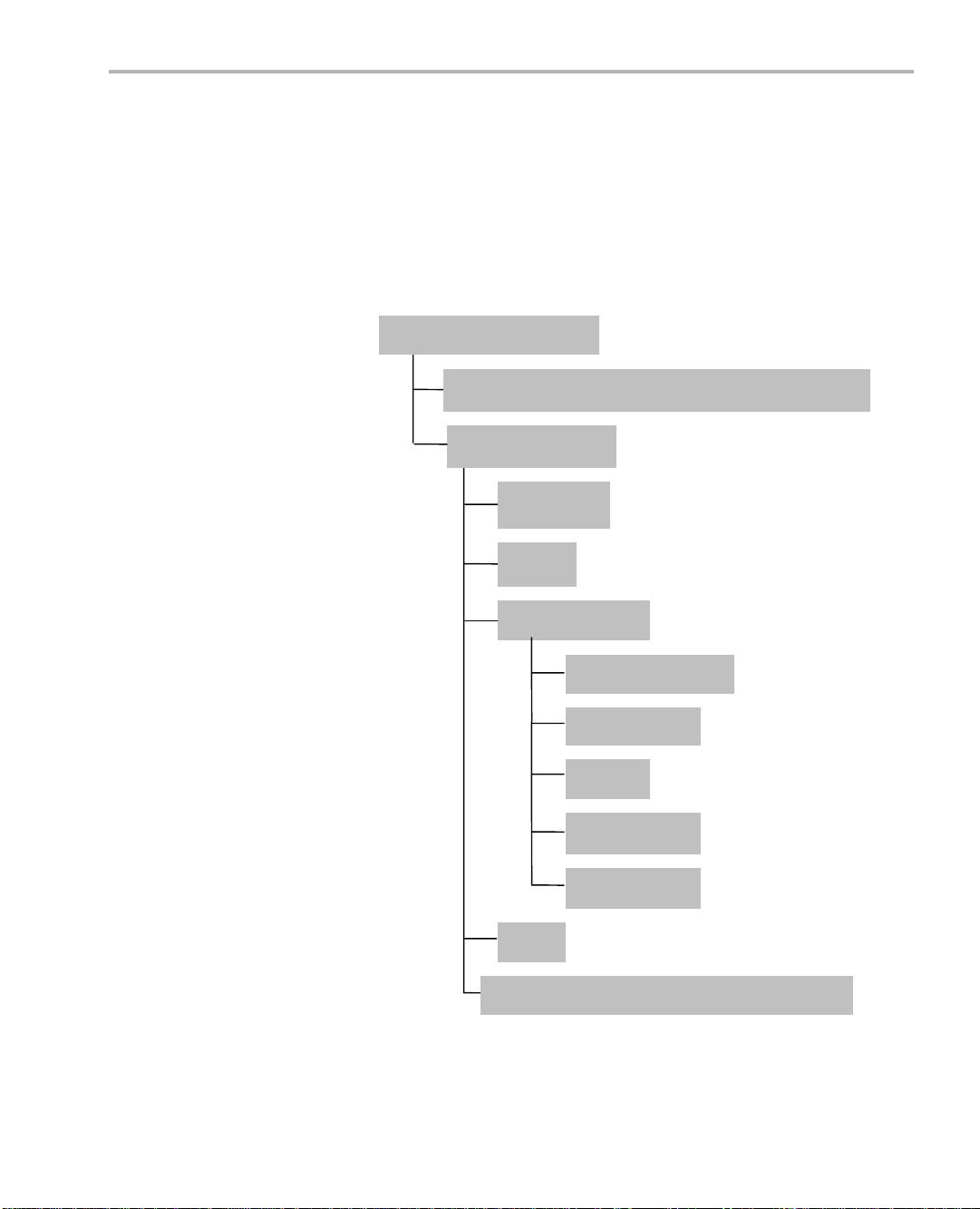
The following files and directories are extracted:
REL_LSP_02_20_#_#
Running the Installation
mvl_5_0_0_demo_lsp_setuplinux_02_20_#_#.bin
PSP_02_20_#_#
examples
docs
board_utilities
u-boot-1.3.3.tar.gz
flash_writers
tools
armubl
dspubl
bin
lsp_psp_02_20_#_#_release_notes.html
2) Move (cd command) to the REL_LSP_02_20_#_# directory that was
extracted.
Installing the Package 2-3
Page 14

Running the Installation
3) To install the Linux kernel, run
mvl_5_0_0_demo_lsp_setuplinux_02_20_#_#.bin on the Linux host.
This is a self-installing executable which installs a tar ball named
LSP_02_20_#_#.tar.gz at the chosen location.
4) Untar the LSP_02_20_#_#.tar.gz tar ball to obtain the kernel
sources.
5) Untar the PSP_02_20_#_#/board_utilities/u-boot-1.3.3.tar.gz file to
obtain the U-Boot sources.
6) Flash writer sources and CCStudio projects are provided in the
PSP_02_20_#_#/board_utilities/flash_writers directory.
7) Pre-compiled binaries for U-Boot, Linux kernel and Flash writers are
provided in the PSP_02_20_#_#/bin directory.
2-4
Page 15

Chapter 3
Installing MontaVista Tools
This chapter explains how to set up the demonstration version of the
MontaVista Pro 5.0 software provided with the kit.
Topic Page
3.1 Software Overview . . . . . . . . . . . . . . . . . . . . . . . . . . . . . . . . . . . . . . . 3–2
3.2 Preparing to Install . . . . . . . . . . . . . . . . . . . . . . . . . . . . . . . . . . . . . . . 3–3
3.3 Installing the Software . . . . . . . . . . . . . . . . . . . . . . . . . . . . . . . . . . . . 3–3
3.4 Setting Up the Build/Development Environment . . . . . . . . . . . . . . . 3–7
3-1
Page 16

Software Overview
3.1 Software Overview
The following MontaVista Linux Pro v5.0.0 compo nents are provid ed:
❏ MontaVista Linux Pro v5.0.0 System Tools. The version provided
❏ MontaVista Linux Pro v5.0.0 Target File System. The software
❏ MontaVista Linux support package (LSP) installer. This is
Texas Instruments, in agreement with MontaVista Software Inc., is
providing a demonstration version of the Linux Professional Edition
v5.0.0 embedded operating system and development tools. The base
software development kit includes a release of this demonstration
version. The demo ve rsio n i s a s ubset o f wha t Mo ntaVista provid es wit h
the full Professional Edition. Tools such as DevRocket
Professional Editi on documentation are not i ncluded, but it is otherwi se
fully functional and useful for customers evaluating the platform. Also,
please note that this release does not include a MontaVista user license,
and no direct customer support, warranty, or indemnification from
MontaVista Software Inc. is provided.
with the software develo pment kit i s the demons tration ver sion. It is
installed by the mvl_5_0_0_demo_sys_setuplinux.bin file.
development kit prov ides a demonstration version. It is installe d by
the mvl_5_0_0_demo_target_setuplinux.bin file.
installed by the mvl_5_0_0_demo_lsp_setuplinux_#_#_#_#.bin file.
TM
and the
3-2
Page 17

3.2 Preparing to Install
On a host system, mou nt the software develo pment kit disks and c opy
the following .bin files to a temporary location with at least 2.3 GB
available space. Since you may delete the installation files after installing
the software, a directory like /tmp is recommended.
❏ mvl_5_0_0_demo_sys_setuplinux.bin
❏ mvl_5_0_0_demo_target_setuplinux.bin
❏ mvl_5_0_0_demo_lsp_setuplinux_#_#_#_#.bin
Ensure that an X g raphic al displa y is avai lable. If you are logging i nto a
remote machine to run the installation, you can set the DISPLAY
environment variable to point to your local X server. For example:
On csh:
host $ setenv DISPLAY <local X server hostname>:0
On ksh or bash:
host $ export DISPLAY=<local X server hostname>:0
Preparing to Install
3.3 I nstalling the Software
Installing the software used by the PSP kit involves performing the
following steps:
❏ Section 3.3.1, Installing the Target Linux Software
❏ Section 3.3.2, Exporting a Shared File System for T arget Access
❏ Section 3.3.3, Testing the Shared File System
3.3.1 Installing the Target Linux Software
This section explains how to install Linux for use on the target board. This
is a demonstration version of MontaVista Linux Pro v5.0.0.
Note that separate versions of Linux are used by the target and your host
Linux workstation. The following Linux host operating systems are
supported for use with the software development kit.
❏ Red Hat Enterprise Linux v3
❏ Red Hat Enterprise Linux v4
Installing MontaVista Tools 3-3
Page 18

Installing the Software
To install the Linux software, follow these steps:
1) Log in as root on your h ost Li nux work station. Thi s wil l allow y ou to
successfully run the graphical installer to install MontaVista Linux.
2) Execute each of the following bin files (where
#_#_#_# is the current
version number) from the temporary location that they were copied in
order to extract the installers for the Linux tools, Linux kernel, and the
file system. If a bin file does not run, make sure these files are
executable (use
chmod +x *.bin).
Instead of the default directory, we suggest that you install in the
/opt/mv_pro_5.0.0 directory.
host $ ./mvl_5_0_0_demo_sys_setuplinux.bin
host $ ./mvl_5_0_0_demo_target_setuplinux.bin
host $ ./mvl_5_0_0_demo_lsp_setuplinux_#_#_#_#.bin
3) After you execute thes e .bin files, make sure the foll owing files are
located in /opt/mv_pro_5.0.0 (or in the /mv_pro_5.0.0 subdirectory of
the directory you chose in place of the default):
■ mvltools5.0.0-no-target.tar.gz
■ mvl5.0.0-target_path.tar.gz
■ LSP_#_#_#_#.tar.gz
4) Go to the location where you will unpack the tar files. For example:
host $ cd /opt/mv_pro_5.0.0
5) Unpack the tar files (as root) by using the following commands:
host $ tar zxf mvltools5.0.0-no-target.tar.gz
host $ tar zxf mvl5.0.0-target_path.tar.gz
host $ tar zxf LSP_#_#_#_#.tar.gz
This creates the MontaVista directory structure under the
/opt/mv_pro_5.0.0/montavista/ directory.
3-4
Note that unpacking these tar files will overwrite any existing files that
were previously installed.
Note: The LSP included with this product is a multi-platform LSP; it
is not configured for a particular platform. As shipped, this LSP
cannot be used to buil d the d emo or e xampl e appl icat ions. It m ust
first be copied to a user area and configured/built for the EVM.
Please see Section 4.2 for instructions.
Page 19

Installing the Software
3.3.2 Exporting a Shared File System for Target Access
Although the EVM's flash memory can contain a Linux file system, during
development it is more conv enient to have the target board N FS moun t
a file system on a host Linux workstation. Once you have tested the
application, you can st ore it on the EVM’s hard drive for a standalone
demonstration.
Before the board can mount a target file system, you must export that
target file system on the host Linux workstation. The file system uses an
NFS (Network File Sy stem) s erv er. The exported file s yst e m wi ll co ntain
the target file system and your executables.
To ex port the file system from your NFS server, perform the following
steps. You only need to perform these steps once.
1) Log in with a user account on the host Linux workstation.
2) Perform the following commands to prepare a location for the
MontaVista file system. For example:
host $ cd /home/<useracct>
host $ mkdir -p workdir/filesys
host $ cd workdir/filesys
3) Switch user to "root" on the host Linux workstation.
host $ su root
4) Perform the follo wing commands to crea te a copy of the target file
system with permissions set for writing to the shared area as
<useracct>. Substitute your user name for <useracct>. If you
installed in a location other than /opt/mv_pro_5.0.0, use your location
in the cp command.
host $ cp -a /opt/mv_pro_5.0.0/montavista/pro/devkit/arm/v5t_le/target/* .
host $ chown -R <useracct> opt
5) Edit the /etc/exports file on the host Linux workstation. Add the
following line for exporting the filesys area, substituting your user
name for <useracct>. Use the full path from root; ~ may not work for
exports on all file systems.
/home/<useracct>/workdir/filesys *(rw,no_root_squash,no_all_squash,sync)
Note: Make sure you d o no t ad d a s pace between the * and ( in the
above command.
6) Still as root, use the f ollowing commands to make the NFS server
aware of the change to its configuration and to invoke an NFS restart.
host $ /usr/sbin/exportfs -av
host $ /sbin/service nfs restart
Installing MontaVista Tools 3-5
Page 20

Installing the Software
Note: Use exportfs -rav to re-export all directories. Use
/etc/init.d/nfs status to verify that the NFS status is running.
7) Verify that the server firewall is turned off:
host $ /etc/init.d/iptables status
If the firewall is running, disable it:
host $ /etc/init.d/iptables stop
3.3.3 Testing the Shared File System
To test your NFS setup, follow these steps:
1) Get the IP add ress of y our hos t Lin ux work statio ns as fo llows . Look
for the IP address associated with the eth0 Ethernet port.
host $ /sbin/ifconfig
2) Open a terminal e mul ati on win dow to c onne ct to the E VM bo ar d vi a
RS-232 using the instructions in Section A.4. If you have a Windows
workstation, you can use HyperTerminal. If you have a Linux
workstation, you might use Minicom.
3) Power on the EVM board, and abort the automatic boot sequence by
pressing a key in the console window (Section A.4).
4) Set the following environment variables in the console window:
EVM # setenv nfshost <ip address of nfs host>
EVM # setenv rootpath <directory to mount>
EVM # setenv bootargs console=ttyS2,115200n8 noinitrd
rw ip=dhcp root=/dev/nfs nfsroot=${nfshost}:${rootpath},
nolock mem=32M
Note that the setenv bootargs command should be typed on a
single line. Also note that you should avoid using the numeric keypad
to enter numbers, as it can sometimes insert extra invisible
characters.
The use of “$(...)” for variable substit ution in U-Boot is deprecated.
Please use "${...}" instead. For more information please see
http://www.denx.de/wiki/view/DULG/CommandLineParsing.
<directory to mount> must match the exports. For example,
The
/home/<useracct>/workdir/filesys.
3-6
Page 21

Setting Up the Build/Dev elopment Envir onment
Hints: You may want to use the prin tenv command to prin t a list of
your environment variables. You can also save these setenv
commands in a .txt file from which you can paste them in the future.
5) Save the environment so that you don't have to retype these
commands every time you cycle power on the EVM board:
EVM # saveenv
6) Boot the board using NFS. See Section 5.4 for information on how to
boot Linux kernel using U-Boot.
7) You can now log in as "root" with no password required.
3.4 Set ti ng Up the Build/De vel opment Environment
To set up the GPP-side development and build environment, follow these
steps:
1) Log in to your user account (and not as root) on the NFS host
system.
2) Set your PA TH so that the MontaVista tool chain host tools and cross
compiler (arm_v5t_l e-gcc) can be found. For exampl e, in a default
installation of the MontaVista LSP, you should add a de finition like
the following to your shell resource file (for example, ~/.bashrc):
PATH="/opt/mv_pro_5.0.0/montavista/pro/devkit/arm/v5t_le/bin:
/opt/mv_pro_5.0.0/montavista/pro/bin:
/opt/mv_pro_5.0.0/montavista/common/bin:$PATH"
If you installed in a location othe r than /opt/m v_pro_5.0.0 , use your
own location in the PATH.
3) Remember to use the following command after modifying your
.bashrc file:
host $ source .bashrc
3.4.1 Writing a Simple Program and Running it on the EVM
Make sure you have per formed the steps in Section 3.3.2, Exporting a
Shared File System for Target Access and Section 3.4, Setting Up the
Build/Development Environment.
Perform the following steps on the NFS host system as user (not as root):
1) host $ mkdir /home/<useracct>/workdir/filesys/opt/hello
2) host $ cd /home/<useracct>/workdir/filesys/opt/hello
Installing MontaVista Tools 3-7
Page 22

Setting Up the Build/Development Environment
3) Create a file called hello.c with the following contents:
#include <stdio.h>
int main() {
printf("Buongiorno!\n");
return 0;
}
4) host $ arm_v5t_le-gcc hello.c -o hello
Perform the followi ng st eps on the target bo ard. You may use either the
target's console window (Section A.4) or a telnet session.
1) target $ cd /opt/hello
2) Run ./hello. The output should be:
Buongiorno!
3-8
Page 23

Chapter 4
Building PSP Component s
This chapter explains how to build various components of the PSP.
Topic Page
4.1 Building U-Boot. . . . . . . . . . . . . . . . . . . . . . . . . . . . . . . . . . . . . . . . . . 4–2
4.2 Building a New Linux Kernel . . . . . . . . . . . . . . . . . . . . . . . . . . . . . . . 4 –2
4.3 Building the SPI Flash User Boot Loader (UBL). . . . . . . . . . . . . . . . 4–3
4.4 Building Flash Writers . . . . . . . . . . . . . . . . . . . . . . . . . . . . . . . . . . . . 4–3
4-1
Page 24

Building U-Boot
4.1 Building U-Boot
Follow these steps to compile U-Boot:
1) Go to the u-boot-1.3.3 directory created by the installation.
2) Run the following commands to build U-Boot:
make distclean
make da830_omapl137_config
make
The compiled u-boot.bin file will be created in the same directory.
The U-Boot build options are specified in the include file
include/configs/da8xx_evm.h, which is in the U-Boot source tree. You
can change the build options by editing this file and re-building the U-Boot
binary.
The following build options can be modified:
❏ Choice of flash supported:
■ CFG_USE_SPIFLASH. When this flag is defined, U-Boot
supports the SPI flash part on the OMAP-L137 EVM DSK board.
The environment variables are stored on SPI flash. This option is
switched on by default.
❏ Environment variable size configuration is through CFG_ENV_SIZE.
Please change this variable when you change the flash type.
❏ Environment variable offset configuration is through
CFG_ENV_OFFSET
4.2 Building a New Linux Kernel
The following are steps to compile the Linux Kernel:
1) Change Directory to Linux source obtained in the installation step.
2) Run the following commands
make distclean ARCH=arm CROSS_COMPILE=arm_v5t_lemake da830_omapl137_defconfig ARCH=arm CROSS_COMPILE=arm_v5t_lemake uImage ARCH=arm CROSS_COMPILE=arm_v5t_le-
3) The compiled uImage is copied into the arch/arm/boot directory
under the kernel tree.
4-2
Page 25

Building the SPI Flash User Boot Loader (UBL)
4.3 Building the SPI Flash User Boot Loader (UBL)
The following steps bui ld the SPI Flash User B oot Loader (UBL) using
CCStudio:
1) Start CCStudio v3.3.
2) From the menus, choose Project->Open. Browse to the
REL_LSP_02_20_#_#/PSP_02_20_#_#/board_utilities/armubl
directory and open the ubl.pjt project.
3) From the menus, c hoose Project->Build. The project build places
the ubl-spi.bin image in the armubl directory.
See Section A.1, Loading the DSP User Bootloader into SPI-Flash
Memory for steps to use the SPI Flash Writer to load the DSP User
Bootloader.
4.4 Building Flash Writers
The following subsection describes how to build the SPI Flash writer.
4.4.1 Building an SPI Flash Writer
An SPI flash writer is used to flash the DSP AIS binary , ARM UBL and UBoot images to S PI flash. It also has the ca pability to flash any given
image at a chosen offset.
Use the following steps to build an SPI Flash writer using CCStudio v3.3:
1) Run CCStudio v3.3.
2) From the menus, choose Project->Open.
3) Browse to the REL_LSP_02_20_#_#/PSP_02_20_#_#/
board_utilities/flash_writers/spiflash_writer/ccsv3.3 directory, and
open the spiflash_writer.pjt project.
4) From the menus, choose Project->Build. The spiflash_writer.out
build image is placed in the spiflash_writer/ccsv3.3/Debug directory.
See Section A.1, Loading the DSP User Bootloader into SPI-Flash
Memory for steps to use the SPI Flash Writer to load the DSP User
Bootloader.
Building PSP Components 4-3
Page 26

4-4
Page 27

Chapter 5
Booting
This chapter describes how to r un the target content that is prov ided as
a part of the PSP package.
Topic Page
5.1 Booting from SPI Flash. . . . . . . . . . . . . . . . . . . . . . . . . . . . . . . . . . . . 5–2
5.2 Driver Configuration in the Linux Kernel . . . . . . . . . . . . . . . . . . . . . 5–3
5.3 Building and Loading Kernel Modules . . . . . . . . . . . . . . . . . . . . . . . 5–8
5.4 Booting the Linux Kernel Using U-Boot . . . . . . . . . . . . . . . . . . . . . 5–10
5-1
Page 28

Booting from SPI Flash
5.1 Booting from SPI Flash
Follow these steps to boot from SPI Flash:
1) Download the DSP and ARM GEL files from
http://support.spectrumdigital.com/boards/evmomapl137. Run the
CCStudio Setup tool and ensure that the DSP and ARM GEL files are
correctly specifie d. The file evmomapl 137_arm.gel is the ARM side
GEL file and evmomapl137_dsp.gel is the DSP side GEL file.
2) Put the EVM in emulation debug mode by setting the SW2 switch as
follows:
Table 5–1 SW2 emulation debug mode settings
Pin# 72103
Position 11110
Note: On EVM revisions A and B, the SW2 switch for Pin #3 is
inverted. That is, OFF = 1 and ON = 0. This problem has been
corrected from EVM revision C onwards.
3) Start CCS tudio and connect to the DSP. After connecting to the DSP,
connect to the ARM. W hen you connect to the D SP, the DSP G EL
file wakes up the ARM, enabling CCStudio to connect to the ARM.
5-2
4) Load the SPI flash er tool that you built in Secti on 4.4.1 (or use the
pre-compiled tool that is shipped in the
REL_LSP_02_20_#_#/PS P_02_20_ #_#/bin d irectory o f the r elease
package) on to the ARM.
5) Run the SPI flasher program.
■ In CCStudio v3.3, you will be prompted for the input file type and
the file path. For booting from SPI, a DSP AIS i mage, S PI UBL ,
and U-Boot are required.
❚ To burn a DS P AIS image, type
dspais as the image type.
When prompted for a file name, provide the path to dsp-spiais.bin file in the bin directory of the release package.
❚ To burn SPI UBL, type
armubl as the image type. When
prompted for a file name, provide the path to the SPI UBL,
which you built in a previous section, or the pre-built ublspi.bin in the bin directory of the release package.
❚ To burn U-Boot, type
uboot as the image type. When
prompted for a file na me, provid e the path to the u-boot.bin
file.
Page 29

6) Once the SPI flash has been wri tten with the AIS file, switc h off the
board and set the SW2 switch on the DSK board as follows:
Table 5–2 Final SW2 settings
Pin# 72103
Position 0101x
7) Power up the board again. The board should boot from SPI flash.
5.2 Driver Configuration in the Linux Kernel
This section descr ibes the procedur e to configure th e kernel to support
various drivers.
To begin configuring the Linux kernel, run the following commands:
make da830_omapl137_defconfig ARCH=arm CROSS_COMPILE=arm_v5t_le-
make menuconfig ARCH=arm CROSS_COMPILE=arm_v5t_le-
To se lect or des elect a featur e in the menus, p ress the Space key after
moving your cursor over the selection box. An asterisk (*) in the selection
box means the feature is currently selected. An empty selection box
means the feature is de-selected. To configure a particul ar feature as a
module, press the Space key until an "M" appears in the selection box.
Driver Configuration in the Linux Kernel
5.2.1 USB 2.0 Configuration
Configuring for Host
The menus appear as follows:
Device Drivers --->
USB support --->
<*> Support for Host-side USB
--- Miscellaneous USB options
[*] USB device filesystem
--- USB Host Controller Drivers
<*> Inventra USB Highspeed Dual Role Controller Support
--- DA830/OMAP-L137 USB support
Driver Mode (USB Host) --->
(X) USB Host
Booting 5-3
Page 30

Driver Configuration in the Linux Kernel
If you need to support ISO devices (such as audio), choose the following:
<*> Reserve ISO Endpoint
If you need to support MSC devi ces (such as pen drives), choose the
following:
--- USB Device Class drivers
<*> USB Mass Storage support
If you need to support HID devices (such as mouse and keyboard),
choose the following:
--- USB Input Devices
<*> USB Human Interface Device(full HID) support
[*] HID input layer support
USB Gadget Support --->
< > Support for USB Gadgets
If you need to support SCSI devices, choose the following
SCSI device support --->
--- SCSI device support
[*] legacy /proc/scsi/support
--- SCSI support type (disk, tape, CD-ROM)
<*> SCSI disk support
5-4
Configuring for Gadget
The menus appear as follows:
Device Drivers --->
USB support --->
< > Support for Host-side USB
<*> Inventra Highspeed Dual Role Controller (TI, ...)
USB Gadget Support --->
<*> Support for USB Gadgets
If you need to support Ethernet gadgets choose the following:
<*>
[*] RNDIS support (EXPERIMENTAL)
USB Gadget Drivers (Ethernet Gadget (w/ CDC Ethernet))
If you need to support File backed storage gadgets, choose the following:
<M> USB Gadget Drivers
<M> File-backed Storage Gadget
Page 31

5.2.2 USB 1.1 Configuration
The menus appear as follows:
Device Drivers --->
USB support --->
<*> Support for Host-side USB
--- Miscellaneous USB options
[*] USB device filesystem
--- USB Host Controller Drivers
<*> OHCI HCD support
If you need to support MSC devi ces (such as pen drives), choose the
following:
--- USB Device Class drivers
<*> USB Mass Storage support
If you need to support HID devices (such as mouse and keyboard),
choose the following:
--- USB Input Devices
<*> USB Human Interface Device(full HID) support
[*] HID input layer support
USB Gadget Support --->
< > Support for USB Gadgets
Driver Configuration in the Linux Kernel
If you need to support SCSI devices, choose the following
SCSI device support --->
--- SCSI device support
[*] legacy /proc/scsi/support
--- SCSI support type (disk, tape, CD-ROM)
<*> SCSI disk support
Booting 5-5
Page 32

Driver Configuration in the Linux Kernel
5.2.3 Audio Configuration
The menus appear as follows:
Device Drivers --->
Sound --->
<*> Sound card support
Advanced Linux Sound Architecture --->
<*> Advanced Linux Sound Architecture
System on Chip audio support --->
<*> ALSA for SoC audio support
<*> SoC Audio support for DA830/OMAP-L137 EVM
[*] DA830/OMAP-L137 McASP0 control by ARM
[ ] DA830/OMAP-L137 McASP1 control by ARM
[ ] DA830/OMAP-L137 McASP2 control by ARM
DA830/OMAP-L137 CODEC --->
(X) Using the TLV3106 CODEC
5.2.4 Graphical LCD Configuration
Note: A Graphical LCD part is not present on the OMAP-L137 DSP
Starter Kit board. The OMAP-L137 So C supports interfacing with
Graphical LCD through the LCD controller, however.
The menus appear as follows:
System Type --->
[ ] Support for NAND flash on UI board
[ ] Support for NOR flash on UI board
Device Drivers --->
Character devices --->
< > DA830/OMAP-L137 Character LCD Support
Graphics support --->
<*> Support for frame buffer devices
<*> DA830/OMAP-L137 Framebuffer support
[*] Use SHARP LQ035Q3DG01 LCD Display
5.2.5 Character LCD Configuration
Note: A Character LCD part is not present on the OMAP-L137 DSP
Starter Kit board. The OMAP-L137 So C supports interfacing with
Character LCD through the LCD controller, however.
5-6
Page 33

The menus appear as follows:
System Type --->
[ ] Support for NAND flash on UI board
[ ] Support for NOR flash on UI board
Device Drivers --->
Graphics support --->
< > Support for frame buffer devices
< > DA830/OMAP-L137 Framebuffer support
Character devices --->
<*> DA830/OMAP-L137 Character LCD Support
5.2.6 NAND Flash Configuration
Note: NAND Flash is not pr esent on t he OMAP-L 137 DSP Starter
Kit board. The OM AP-L137 SoC supports interfacing with NA ND
Flash, however.
The menus appear as follows:
System Type --->
[*] Support for NAND flash on UI board
[ ] Support for NOR flash on UI board
Driver Configuration in the Linux Kernel
Device Drivers --->
Character devices --->
< > DA830/OMAP-L137 Character LCD Support
Graphics support --->
< > Support for frame buffer devices
Memory Technology Devices (MTD) --->
[*] Command line partition table parsing
NAND Flash Device Drivers --->
<*> NAND Device Support
<*> NAND Flash device on DaVinci SoC
5.2.7 NOR Flash Configuration
Note: NOR Flash is not present on the OMAP-L137 DSP St arter Kit
board. The OMAP-L137 SoC supports interfacing with NOR Flash,
however.
Booting 5-7
Page 34

Building and Loading Kernel Modules
The menus appear as follows:
System Type --->
[ ] Support for NAND flash on UI board
[*] Support for NOR flash on UI board
Device Drivers --->
Character devices --->
< > DA830/OMAP-L137 Character LCD Support
Graphics support --->
< > Support for frame buffer devices
Memory Technology Devices (MTD) --->
RAM/ROM/Flash chip drivers --->
<*> Detect flash chips by CFI probe
<*> Support for AMD/Fujitsu flash chips
Mapping drivers for chip access --->
[*] Support non-linear mappings of flash chips
<*> Latch-assisted Flash Chip Support
5.2.8 MMC/SD Configuration
The menus appear as follows:
Device Drivers --->
MMC/SD Card support --->
<*> MMC support
<*> MMC block device driver
<*> TI DAVINCI Multimedia Card Interface support
5.3 Building and Loading Kernel Modules
This section describe s how to load the var ious drivers which have been
compiled as kernel modules.
T o build all features configured as modules issue the following command:
make modules ARCH=arm CROSS_COMPILE=arm_v5t_le-
To i nstall the compile d modules int o the DUT root fi le system issue the
following command:
make modules modules_install INSTALL_MOD_PATH=<root fs path>
ARCH=arm CROSS_COMPILE=arm_v5t_le-
5-8
Page 35

Building and Loading Kernel Modules
where the <root fs path> is the path of y our root fi le sys tem on the host
machine. This is usually /opt/montavista/pro/devkit/arm/v5t_le/target/.
On the target, use the
module. Use the
the
rmmod command to remove the module. The following subsection
modprobe command to load the module. You can use
modinfo command to get information on the
provides an example that loads the USB file storage gadget module. You
can use similar steps for other driver modules.
5.3.1 Loading USB 2.0
To load the file-based storage module follow these steps:
1) Issue the
You should see output similar to the following:
# modinfo g_file_storage
filename: /lib/modules/2.6.18_pro500/kernel/drivers/usb/gadget/g_file_storage.ko
license: Dual BSD/GPL
author: Alan Stern
description: File-backed Storage Gadget
depends: musb_hdrc
vermagic: 2.6.18_pro500 preempt mod_unload ARMv5 gcc-4.2
parm: file:names of backing files or devices (array of charp)
parm: ro:true to force read-only (array of bool)
parm: luns:number of LUNs (uint)
parm: removable:true to simulate removable media (bool)
parm: stall:false to prevent bulk stalls (bool)
2) Insert the g_file_storage.ko module with the following command
where
storage space:
modinfo g_file_storage command at the DUT prompt.
/dev/blockdevX is the storage device acting as the actual
# modprobe g_file_storage file=/dev/blockdevX
3) Remove the module by using the following command:
# rmmod g_file_storage
Booting 5-9
Page 36

Booting the Linux Kernel Using U-Boot
5.4 Booting the Linux Kernel Using U-Boot
Booting the kernel requires a vali d kernel image (u Image) and a target
filesystem. File systems of various kinds are supported by Linux kernel.
A pre-built RAM Disk image can be found in your MontaVista tools
installation <linux_install_dir>/pro/devkit/arm/v5t_le/images/ramdisk.gz
directory. A target filesystem hierarchy suitable for export through NFS is
found in the <linux_install_dir>/pro/devkit/arm/v5t_le/target/ directory.
To bo ot the L inux kern el, use t he U -Boot tftp comm and to downloa d th e
kernel uImage to SDRAM. You can then choose to directly boot the newly
downloaded kernel or to write it to non-volatile memory using U-Boot
commands and then copy the k ernel to SDRAM from this memory for
subsequent boots. Please see Section A.3 of this user guide for
information on setting up a TFTP server.
To use TFTP do wnload, you must first set up the DUT IP parameters.
The easiest way to do this is to use the DHCP server on your network.
1) Use DHCP to set the EVM IP address.
U-Boot> setenv autoload no
U-Boot> dhcp
2) Set the IP address of the server (this may also be obtained from
DHCP).
5-10
U-Boot> setenv serverip <ip addr of server>
3) Set the name of the image to be downloaded (this may also be
obtained from DHCP).
U-Boot> setenv bootfile <Linux kernel image file name>
You can get help on U-Boot commands by using the U-Boot "help"
command. Typing help at the U-Boot command prompt gives a list of
commands supporte d. Typing "help" followed by a command name give
help regarding that particular command. Help on U- Boot commands is
also available at http://www.denx.de/wiki/view/DULG/UBoot.
Page 37

5.4.1 Booting from SDRAM
Download the kernel and ramdisk image from Ethernet (using TFTP) into
SDRAM. Then boot the kernel image from SDRAM. To achieve this, use
the following settings (on a single line) for the U-Boot environment
variables bootargs and bootcmd and reboot the DUT.
setenv bootargs 'mem=32M console=ttyS2,115200n8
root=/dev/ram0 rw initrd=0xc1180000,4M ip=dhcp'
setenv bootcmd 'tftp 0xc0700000 uImage; tftp 0xc1180000
ramdisk.gz; bootm 0xc0700000'
5.4.2 Booting from SPI Flash
You can download the kernel and ramdisk images via Ethe rnet (using
TFTP) once into SPI Flash and boot directly from SPI Flash on
subsequent reboots. To enable SPI flash support in U-Boot , th e uImag e
must be compiled with the CON FIG_USE_SPIFL ASH macro defined in
the include/configs/da8xx_evm.h file.
To boot from SPI flash follow these steps.
1) Select the serial flash device as follows:
Booting the Linux Kernel Using U-Boot
sf probe 0
2) Download ramdisk.gz and copy it to the SPI flash partition as follows:
tftp 0xc1180000 ramdisk.gz
sf erase 0x60000 0x180000
sf write 0xc1180000 0x60000 0x180000
3) Download uImage and copy it to the SPI flash partition as follows:
tftp 0xc0700000 uImage
sf erase 0x1E0000 0x220000
sf write 0xc0700000 0x1E0000 0x220000
4) Set the bootargs and bootcmd environment variables to boot from
SPI flash as follows:
setenv bootargs 'mem=32M console=ttyS2,115200n8
root=/dev/ram0 rw initrd=0xc1180000,4M ip=dhcp'
setenv bootcmd 'sf probe 0;sf read 0xc0700000 0x1E0000
0x220000; sf read 0xc1180000 0x60000 0x180000; bootm
0xc0700000'
Note: The SPI flash size on the DSK board is 4 MB in size. Please ensure
that the kernel and ramdisk images can fit into the flash before attempting
to boot from SPI flash.
Booting 5-11
Page 38

Booting the Linux Kernel Using U-Boot
5.4.3 Booting from USB Storage
U-boot includes support for loading files from USB mass storage devices
into memory. This section explains how to config ure U-Boot to enable
USB and mass storag e support in U-Boot and the U-Boot co mmands
used for initializing and loading files from mass storage devices
connected to the USB 2.0 port on the EVM.
Two macros must be defined in the inc lude/configs/ da8xx_evm.h fi le to
enable support for USB and MSC modules. Y ou can compile U-Boot after
enabling the following macros:
❏ CONFIG_USB_DA8XX. This macro enab les the ho st control ler and
USB host modules in U-Boot.
❏ CONFIG_USB_STORAGE. This macro enables the USB MSC
module in U-Boot.
You can use the followin g sequence of U-Boot commands to load the
Linux kernel image from the USB mass storage device:
1) usb reset This command initiates the USB enumeration process to
identify all the devices connected to the USB 2.0 port. U-Boot
supports devices dir ectly connected to the USB port or via high/full
speed hubs. After the command executes, the number of USB
devices found on the bus and the number of storage devices
detected is displayed. The command
usb reset. For example, the following command initiates USB
enumeration and identifies the storage devices attached to USB.
usb start also is equivalent to
5-12
U-Boot> usb reset
2) fatload usb dev[:part] address filename This command loads a
file from a mass storage device. For the
dev parameter you should
specify the number of the sto rage device found on the USB bus by
the
usb reset command. The usb storage devices are nu mbered
sequentially from zero onwards. For
number on the mass storage device. For
address in memor y where the file has to be loaded. For
part specify the partition
address specify the st arting
filename
specify the file to be loaded from the mass storage device. For
example, the followin g comma nd load s the Lin ux kerne l image from
USB storage device 0 partition 1 to SDRAM.
U-Boot> fatload usb 0:1 0xC0700000 uImage
You can use the following additional commands to identify the device
attached:
❏ fatls usb dev[:part][directory] This command lists the files on a
USB mass storage device. The
dev and part parameters are the
Page 39

Booting the Linux Kernel Using U-Boot
same as for the fatload command. For the optional directory
parameter you can specify the directory from which the contents
should be listed. For example, the following command lists the
contents of the first partition on the first USB storage device.
U-Boot> fatls usb 0:1
❏ usb tree This command displays a tree of all USB devices
enumerated during the
usb reset command execution.
❏ usb info This command displays device information for all USB
devices enumerated during the
usb reset command execution.
❏ usb read addr startblock numblocks This command reads the
contents of the logical sectors in the mass storage device to memory.
❏ usb stop This command disables the US B module and the USB
PHY.
Booting 5-13
Page 40

5-14
Page 41

Appendix A
Additional Procedures
This appendix describes optional procedures you may use depending on
your setup and specific needs.
Topic Page
A.1 Loading the DSP User Bootloader into SPI-Flash Memory. . . . . . . A–2
A.2 Building the SPI DSP AIS Binary . . . . . . . . . . . . . . . . . . . . . . . . . . . . A–3
A.3 Setting Up a TFTP Server . . . . . . . . . . . . . . . . . . . . . . . . . . . . . . . . . . A–4
A.4 Connecting to a Console Window . . . . . . . . . . . . . . . . . . . . . . . . . . . A–5
A-1
Page 42

Loading the DSP User Bootloader into SPI-Flash Memory
A.1 Loading the DSP User Bootloader into SPI-Flash Memory
Section 4.3 describes how to build the DSP User Bootloader (UBL). You
can use the following steps to flash the DSP UBL into SPI-Flash using the
DSP flash utility:
1) Open CCStudio 3.3 and connect to the DSP.
2) From the menus, choose Project->Open. Browse to the
REL_LSP_02_20_#_#/PSP_02_20_#_#/board_utilities/flash_writers
/spi_flash_writer/ccsv3.3 directory and open the spiflash_writer.pjt
project.
3) Choose either the debug or release configuration. Then, choose
Project->Build Active Project to build the flash utility project. (You
may have already built this in Section 4.4.1.)
4) Run the flash utility. It should display the following messages:
SF: Got idcode ef 30 16
SF: Detected W25X32 with page size 256, total 4194304 bytes
Flash page size: 256 bytes
Flash sector size: 4096 bytes
Starting SPIWriter.
Enter the image type (one of "dspais" "armubl" "uboot" "other")
5) A stdin window opens to ask for the type of binary to be flashed. Type
dspais in the window.
A-2
6) A second stdin window opens to ask for the path of the user
bootloader binary file. T ype the path of the file to be flashed. Note that
the DSP User Bootloader to be flashed needs to be in AIS format. For
details on preparing an AIS bootloader, please see TI application
report SPRAB04.
7) The flash utility continues displaying m essages, indicating that i t is
flashing the bootloader into SPI-Flash. Once it runs successfully, the
following message is shown.
Reading verifying the file.. Files matched
8) Disconnect CCStudio from the DSP and switch off the board. Set the
SW2 switch on board as follows:
Pin# 72103
Position 0101x
9) Power on the board. The DSP should boot from SPI-Flash.
Page 43

A.2 Building the SPI DSP AIS Binary
Building the DSP AIS binary requires CCStudio v3.3 and the AIS
generation tool. Typically you should not need to r ebuild the DSP AIS
binary. In most cases, you can use the binary provided in the
REL_LSP_02_20_#_#/PSP_02_20_#_#/bin directory.
To rebuild, follow these steps:
1) Start CCStudio v3.3.
2) From the menus, choose Project->Open. Browse to the
REL_LSP_02_20_#_#/PSP_02_20_#_#/board_utilities/dspubl
directory and open the ubl.pjt project.
3) From the menus, c hoose Project->Build. The project build places
the ubl-spi.out image in the spi/dspubl directory.
4) Download and install the AISgen tool on a Windows PC by following
the instructions in Section 5 of Using the D800K001 Bootloader
(SPRAB04).
5) Open an MS-DOS comm and window and c d to the AIS Genera tion
tool installation directory.
6) Execute the following command:
Building the SPI DSP AIS Binary
hexgen -romid D800K001 -seqread -crc 1 -spiclk 0 -appln
<PATH>:REL_LSP_02_20_#_#/PSP_02_20_#_#/board_utilities/dspubl/spi/ubl-spi.out -output <PATH>REL_LSP_02_20_#_#/
PSP_02_20_#_#/bin/dsp-spi-ais.bin
The resulting dsp-spi-ais.bin file is the SPI DSP AIS binary.
Addition al Procedures A-3
Page 44

Setting Up a TFTP Server
A.3 Setting Up a TFTP Server
You can check to see if a TFTP server is set up with the following
command:
host $ rpm -q tftp-server
If it is not set up, you can follow these steps:
1) If you have not yet installed MontaVista Linux Demo Edition (see
Section 3.3.1), you can down lo ad a TFTP serv er for you r Linux hos t
from many locations on the Internet. Search for "tftp-server".
2) To install TFTP, use this command, where
-#.#-# is the version
number portion of the filename:
host $ rpm -ivh tftp-server-#.#-#.rpm
You should see the following output:
warning: tftp-server-#.#-#.rpm:
V3 DSA signature: NOKEY, key ID 4f2a6fd2
Preparing... ################################### [100%]
1:tftp-server ################################### [100%]
3) Confirm that TFTP is installed with this command:
host $ /sbin/chkconfig --list | grep tftp
If you want to turn on the TFTP server, use this command:
/sbin/chkconfig tftp on
The default root location for servicing TFTP files is /tftpboot.
A-4
Page 45

A.4 Connecting to a Console Window
You can open a console window that allow s you to watch and interrupt
EVM boot messages by following these steps:
1) Connect a seria l cable betwee n the serial port on the EVM and the
serial port (for example, COM1) on a PC.
2) Run a HyperTerminal session on the PC and configure it to connect
to that serial port with the following characteristics:
■ Bits per Second: 115200
■ Data Bits: 8
■ Parity: None
■ Stop Bits: 1
■ Flow Control: None
3) When you power on the EVM, you will see boot sequence messages.
You can press a key to interrupt the boot sequence and type
commands in the U-Boot command shell. In this guide, commands to
be typed in the U-Boot shell are indicated by an
EVM # prompt.
Connecting to a Console Window
Addition al Procedures A-5
Page 46

A-6
Page 47

Index
A
AIS generation tool A-3
audio configuration 5-6
B
.bashrc file 3-7
build environment, setting up 3-7
C
CCStudio
booting from SPI Flash using 5-2
building DSP AIS binary using A-3
building Flash writers using 4-3
building SPI Flash UBL using 4-3
loading DSP UBL into SPI-Flash me mory using A-
2
versions supported 1-2
(see also NAND Flash writer; SPI Flash writer)
CCStudio Setup tool 5-2
CFG_ENV_OFFSET environment variable 4-2
CFG_ENV_SIZE environment variable 4-2
CFG_USE_SPIFLASH flag 4-2
character LCD configuration 5-6
CONFIG_USB_DA8XX macro 5-12
CONFIG_USB_STORAGE macro 5-12
configuration
kernel drivers 5-3
console window, connecting to A-5
D
da8xx_evm.h file 4-2
development environment , setting up 3-7
DISPLAY environment variable 3-3
downloading PSP package 2-2
drivers
configuration 5-3
DSP AIS binary
for booting from SPI Flash 5-2
building A-3
DSP flash utility A-2
DSP User Bootloader, loading into SPI-Flash
memory A-2
E
EVM # prompt A-5
EVM (Evaluation Module)
boot messages, watching and interrupting A-5
file system in flash memory of 3-5
PSP package support for 1-2
system requ irements for 2-2
test program for 3-7
exports file 3-5
F
fatload usb command 5-12
fatls usb command 5-12
G
graphical LCD configuration 5-6
H
host operating system, Linux versions supported
for 3-3
I
installation
of PSP package 2-3
of target Linux software 3-3
K
kernel
driver configuration 5-3
Index--1
Page 48

Index
L
LCD configuration 5-6
Linux
installation for target 3-3
MontaVista Linux Pro 1-2, 3-2, 3-3
versions supported for host operating system 3-3
Linux kernel
booting 5-10
building 4-2
driver configuration 5-3
loading from USB mass storage device 5-12
LSP (see MontaVista Linux support package)
M
MMC configuration 5-8
MontaVista (MV) Linux Pro 5.0 3-2
demonstration version of, in PSP package 1-2
installation for target 3-3
MontaVista Linux support package (LSP)
installer 3-2
multi-platform issues regarding 3-4
N
NAND Flash writer 1-2
configuration 5-7
NFS server
exporting file system from 3-5
testing shared file system setup 3-6
NOR Flash configuration 5-7
O
OMAP-L137 EVM 1-2
(see also EVM (Evaluation Module)
operating system requirements (see system require-
ments)
P
PATH environment variable, setting MontaVista loca-
tions in 3-7
PSP (Platform Support Product) 1-2
downloading 2-2
installing 2-3
system requirements for 2-2
S
SD card configuration 5-8
SPI DSP AIS binary, building A-3
SPI Flash User Boot Loader (UBL)
for booting from SPI Flash 5-2
building 4-3
SPI Flash writer 1-2
booting from 5-2
building 4-3
U-boot build option for 4-2
SPI-Flash memory, loading DSP User Bootloader
into A-2
system requirements
for host operating system 3-3
for Linux EVM Driver 2-2
T
target board
exporting file system for 3-5
installing Linux for 3-3
tftp command 5-10
TFTP server, setting up A-4
U
UBL (see SPI Flash User Boot Loader)
U-Boot
for booting from SPI Flash 5-2
commands 5-10
compiling 4-2
included in PSP package 1-2
uImage kernel 5-10
USB 1.1 5-5
USB 2.0 5-3
usb info command 5-13
USB mass storage device, loading Linux kernel
from 5-12
usb read command 5-13
usb reset command 5-12
usb start command 5-12
usb stop command 5-13
usb tree command 5-13
User Boot Loader (see SPI Flash User Boot Loader)
Index--2
 Loading...