

Page 1

LMX248x Evaluatio n Boa rd
User's Guide
Revised – March 2014
SNAU137
Page 2
LMX248x
Evaluation Board Operating I nstructions
www.ti.com
2 SNAU137 LMX248x Evaluation Board User’s Guide Revised - March 2014
Copyright © 2014, Texas Instruments Incorporated
Page 3

www.ti.com
Table of Contents
EQUIPMENT ..................................................................................................................................................................................... 4
BASIC OPERATION ........................................................................................................................................................................... 5
LMX2485 BOARD INFORMATION .................................................................................................................................................... 7
PLL PHASE NOISE ..................................................................................................................................................................... 9
RF
PLL FRACTIONAL SPURS ......................................................................................................................................................... 11
RF
PLL LOCK TIME ...................................................................................................................................................................... 12
RF
PLL LOCK TIME ........................................................................................................................................................................ 14
IF
PLL PHASE NOISE ..................................................................................................................................................................... 15
IF
PLL SPURS ................................................................................................................................................................................ 16
IF
LMX2486
PLL PHASE NOISE ................................................................................................................................................................... 18
RF
PLL FRACTIONAL SPURS ......................................................................................................................................................... 20
RF
PLL LOCK TIME (WITH A SPECTURM ANALYZER) .................................................................................................................. 21
RF
PLL PHASE NOISE ..................................................................................................................................................................... 22
IF
PLL SPURS ................................................................................................................................................................................ 23
IF
PLL LOCK TIME ........................................................................................................................................................................ 24
IF
LMX2487
INDING A VCO ............................................................................................................................................................................ 25
F
EPLACING THE VCO W IT H A FOOTPRINT COMPATIBLE VCO ...................................................................................................... 26
R
APPENDIX A: SCHEMATICS ............................................................................................................................................................ 27
PPENDIX B: BUILD DIAGRAMS .................................................................................................................................................... 28
A
PPENDIX C: BIL L OF MATERIALS ................................................................................................................................................ 31
A
PPENDIX D: QUICK START FOR EVM COMMUNICATIONS ........................................................................................................... 34
A
BOARD INFORMATION .................................................................................................................................................. 17
BOARD INFORMATION .................................................................................................................................................. 25
Revised - March 2014 LMX248x Evaluation Board User’s Guide SNAU137 3
Copyright © 2014, Texas Instruments Incorporated
Page 4

www.ti.com
Equipment
Power Supply
The Power Supp ly should be a low noise power s upply. An Agilent 6623A Triple power supply with LC filters on the
output to reduce noise was used in creating these evaluation board instructions.
Signal Generator
The Signal Generator should be capable of frequencies and power level required for the part. A Rohde & Schwarz SML03
was used in creating these evaluation board instructions.
Phase Noise / Spectrum Analyzer
For measuring phase noise an Agilent E505 2A is recommended. An Agilent E4445A PSA Spectr um Analyzer with the
Phase Noise option is also usable although the architecture of the E5052A is superior for phase noise measurements. At
frequencies less than 100 MHz the local oscillator noise of the PSA is to o high and measurements will be of the loc al
oscillator, not the device under test.
Oscilloscope
The oscilloscope and probes should be capable of measuring the output frequencies of interest when evaluating this
board. The Agilent Infiniium DSO81204A was used in creating these evaluation board instructions.
4 SNAU137 LMX248x Evaluation Board User’s Guide Revised - March 2014
Copyright © 2014, Texas Instruments Incorporated
Page 5

www.ti.com
Basic Operation
1. Connect the signal generator output to the OSCin input of the board. For this ex ample we use a 10 MHz sin
signal at +5dBm power level.
2. Connect a low noise 3.3 V power supply to the Vcc connector located at the top left of the board.
3. Please see Appendix D for quick start on interfacing the board. Connect PC to the uWire header.
4. Start CodeLoader4.exe.
5. Click “Select Device” “PLL-Fractional” LMX248x depending on which chip is on your board.
Revised - March 2014 LMX248x Evaluation Board User’s Guide SNAU137 5
Copyright © 2014, Texas Instruments Incorporated
Page 6

www.ti.com
6. Select USB or LPT Communication Mode on the Port Setup tab as appropriate.
7. Click “CTRL + L” to load settings into device
6 SNAU137 LMX248x Evaluation Board User’s Guide Revised - March 2014
Copyright © 2014, Texas Instruments Incorporated
Page 7

RF LOOP FILTER
Theoretical ( NOT Measured ) Simulation
(Done with EasyPLL at http://www.ti.com/lsds/ti/wireless)
Pole Ratio
T3 /T1
VCO
CPoRF
2.7 nF
47 nF
820 Ω
270 pF
180 pF
3.9 KΩ 5.6 KΩ
Kφ
400 uA
Comparison
Frequency
Output
Frequency
2400 – 2480
MHz
PLL Supply
2.5 Volts
VCO Supply
3 Volts
Other Information
VCO Used
VARIL2450U
VCO Gain
55 MHz/Volt
VCO Input
Capacitance
www.ti.com
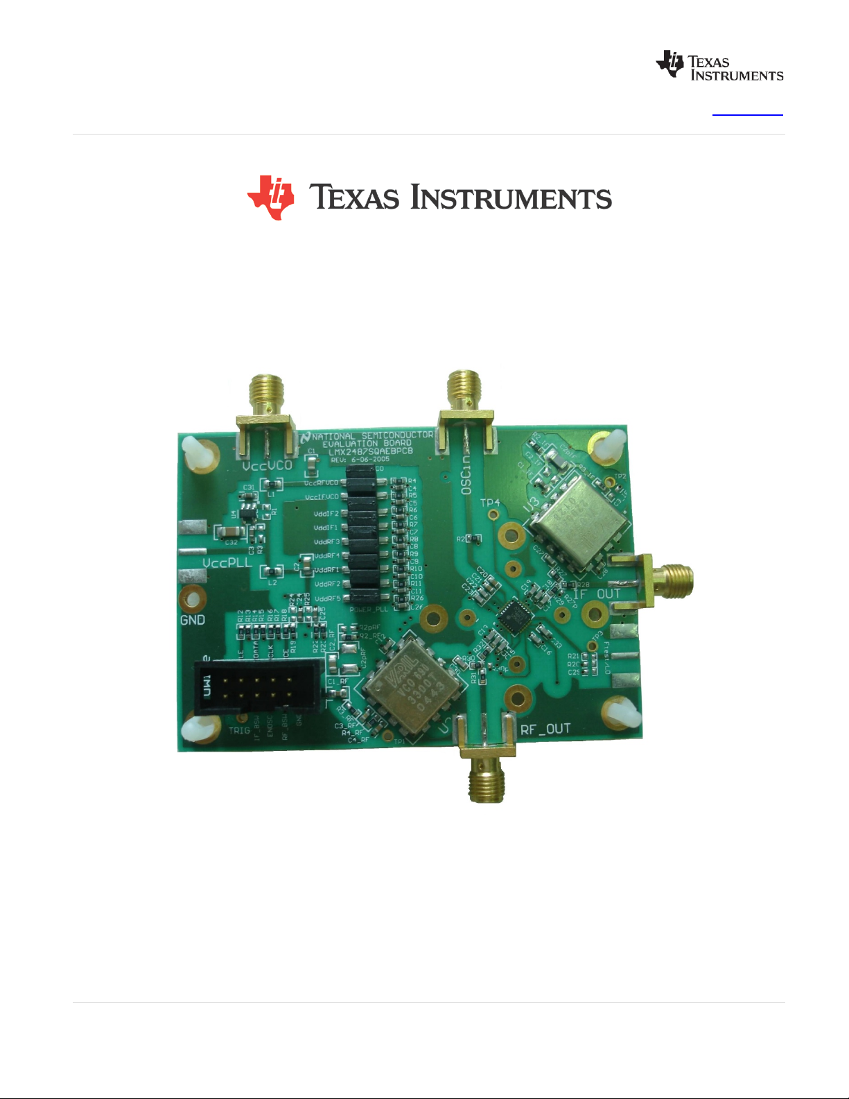
LMX2485 Board Information
TM
The LMX2485 Evaluation Board simplifies evaluat ion of the LMX2485 2.6 GHz/0.8 GHz PLLatinum
synthesizer. The board enables a ll performance measurements with no additional support circuitry. The evaluation
board consists of a LMX 2485 device, a RF VCO module and IF VCO & RF/IF loop fi lters built by discrete c omponents.
The SMA flange mount c onnector s are pr ovided f or ex ternal r ef erenc e inp ut, RF an d I F VCO outpu ts , and t he power and
grounding connection. A cable ass embly is bundled with the evaluation boar d f or c onnec ting to a PC throu gh t he parall el
printer port. By means of USB2ANY-uWire seria l port e mulation, the CodeLoader sof tware inclu ded c an be ru n o n a PC
to facilitate the LMX2485 internal register programming for the evaluation and measurement.
dual frequency
Phase Margin 48.3 deg
Loop Bandwidth 11.3 KHz
2400 – 2480 MHz to 1
Lock Time
KHz tolerance in
247 uS w/o Fastlock
Pole Ratio
Spur Gain
@ 200 KHz
40.2 %
T4/T3
36.3 %
-45.8 dB
Settings for Operation
10 MHz
22 pF
Revised - March 2014 LMX248x Evaluation Board User’s Guide SNAU137 7
Copyright © 2014, Texas Instruments Incorporated
Page 8

IF LOOP FILTER
Theoretical ( NOT Measured ) Simulation ( Done with EasyPLL at www.ti.com )
760 - 780 MHz
uS
VCO
CPoRF
1.8 nF
10 nF
8.2 KΩ
Open
Open
0 Ω 0 Ω
Settings for Operation
Kφ
4 mA
Comparison
Frequency
Output
Frequency
PLL Supply
2.5 Volts
VCO Supply
3 Volts
Other Information
VCO Used
VARIL191-773U
VCO Gain
18 MHz/Volt
VCO Input
Capacitance
www.ti.com
Phase Margin 47.1 deg Lock Time
MHz to 1 KHz
tolerance in 453
Loop Bandwidth 5.1 KHz
Spur Gain
@ 200 KHz
22.1 dB
50 kHz
760 - 780 MHz
100 pF
8 SNAU137 LMX248x Evaluation Board User’s Guide Revised - March 2014
Copyright © 2014, Texas Instruments Incorporated
Page 9
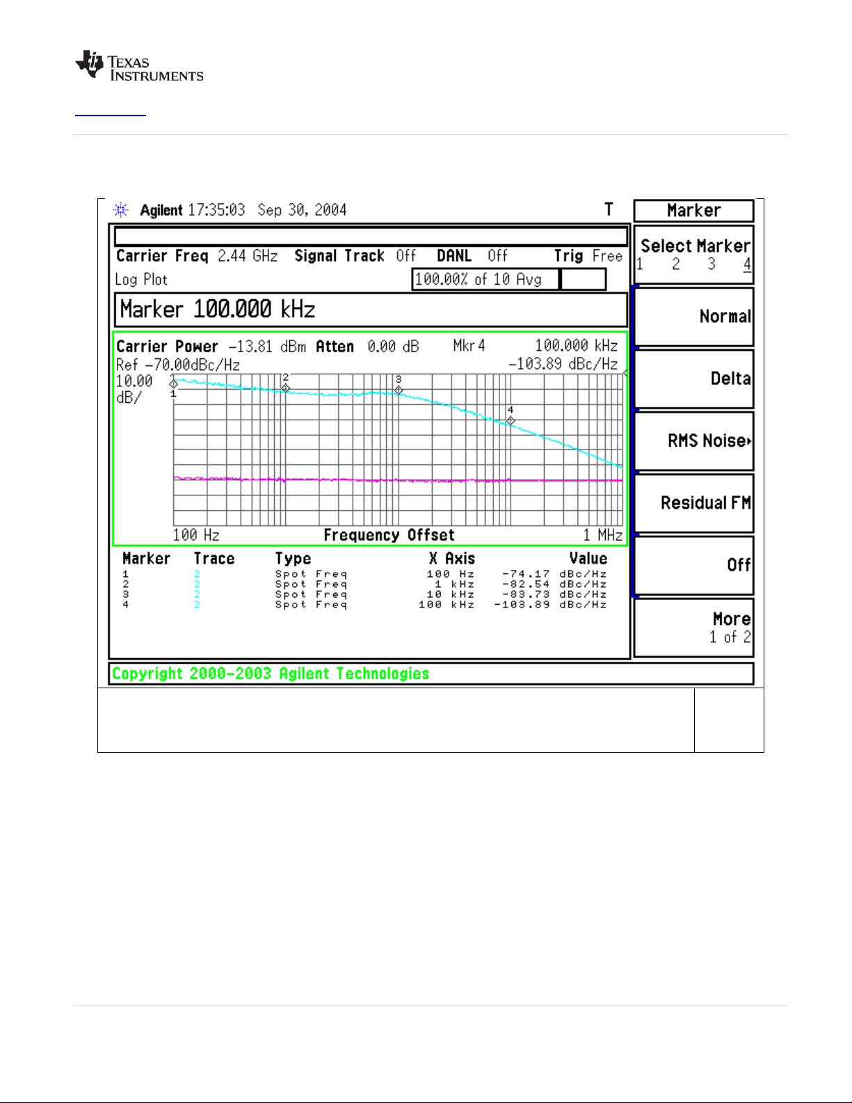
Loop Bandwidth is about 10 kHz. Note that the phase noise gradually improves as one goes farther
noise could still be degrading the in-band phase noise.
www.ti.com
RF PLL Phase Noise
from the carrier. Also note that this is done with 200 uA of current, and the true phase noise
capability of the part is not shown here bec ause the phase noise is worse, and the VCO phase
Revised - March 2014 LMX248x Evaluation Board User’s Guide SNAU137 9
Copyright © 2014, Texas Instruments Incorporated
Page 10

www.ti.com
For this plot, the charge pump was increased to 1600 uA. This improves the PLL phase noise performance and
lower current allows one to experiment with lower comparison frequencies like 2.5 MHz, 5 MHz, and 10 MHz.
also increases the loop bandwidth so the tr ue P LL performance can be seen. The reason that the origina l loop
filter was not designed for 1600 uA cur rent was that it makes the loop filter capacitors 8X larger and als o, the
10 SNAU137 LMX248x Evaluation Board User’s Guide Revised - March 2014
Copyright © 2014, Texas Instruments Incorporated
Page 11

www.ti.com
RF PLL Fractional Spurs
At 2400.2 MHz output frequency, the primary fr actional spur at 200 kHz is
-70.7 dBc, and the sub-fractional spur at 100 kHz is -69.5 dBc.
At 2440.2 MHz output f requency, the primary fr actional spur at 200 kHz is
-78.9 dBc, and the sub-fractional spur at 100 kHz is -72.9 dBc.
At 2480.2 MHz output f requency, the primary fr actional spur at 200 kHz is
-80.8 dBc, and the sub-fractional spur at 100 kHz is -73.4 dBc.
Revised - March 2014 LMX248x Evaluation Board User’s Guide SNAU137 11
Copyright © 2014, Texas Instruments Incorporated
Page 12
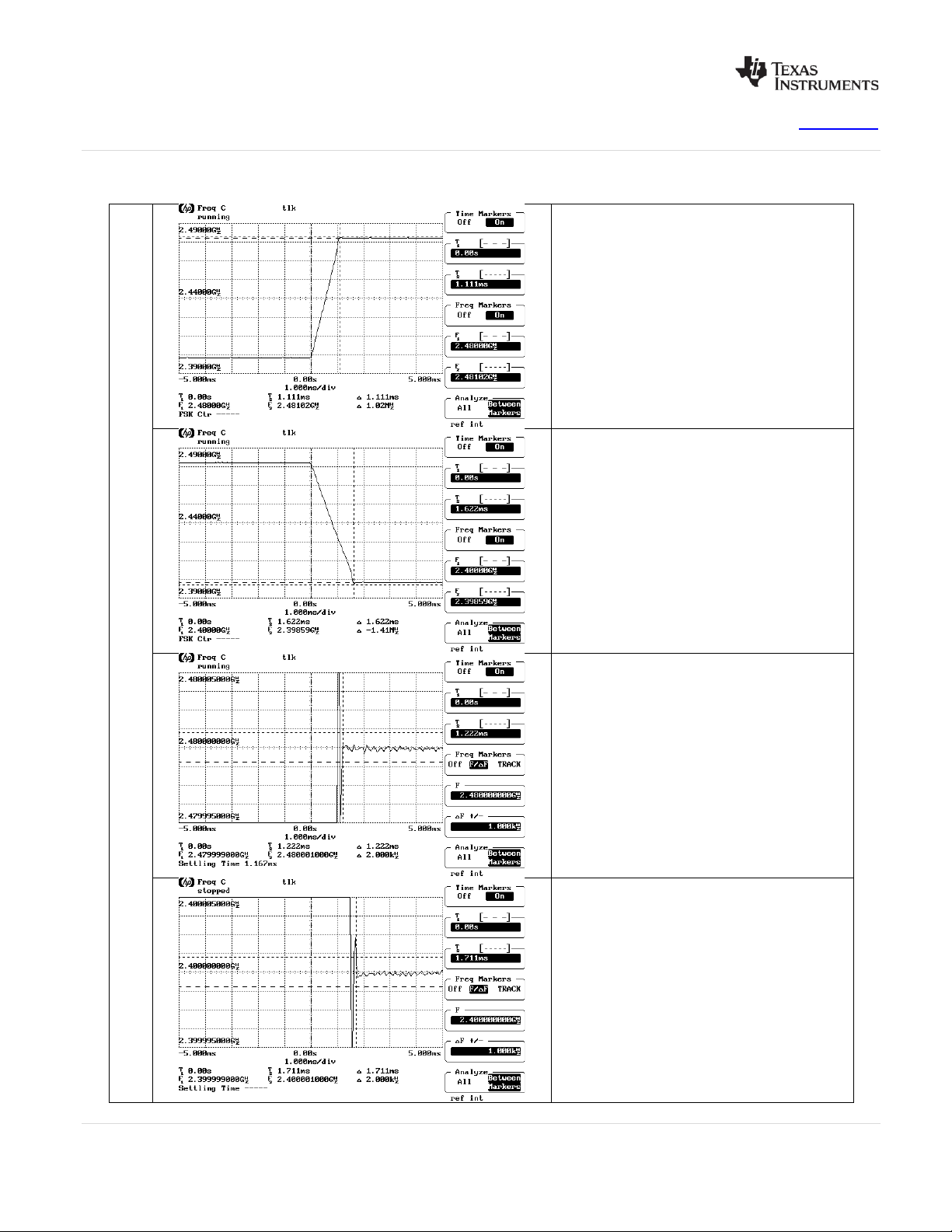
RF PLL Loc k Time
www.ti.com
Peak time withou t cycle slip
reduction is 1110 uS.
Peak time withou t cycle slip
reduction is 1622 uS.
No CSRC. RF_TOC=0
Positive lock time is 1220 uS
Negative Lo ck time i s 171 1 uS
12 SNAU137 LMX248x Evaluation Board User’s Guide Revised - March 2014
Copyright © 2014, Texas Instruments Incorporated
Page 13

www.ti.com
RF PLL Loc k Time
Peak time wi th cy cle slip r eduction
is 222 uS.
Peak time wi th cy cle slip r eduction
is 222 uS.
Positive lock time is 345 uS
Cycle Slip Reduction Enabled. RF_TOC=500
Negative Lo ck time i s 378 uS
Revised - March 2014 LMX248x Evaluation Board User’s Guide SNAU137 13
Copyright © 2014, Texas Instruments Incorporated
Page 14

IF PLL Lock Time
www.ti.com
Peak time is 97.8 uS
Peak Time is 133.3 u S
Positive Lo ck time is 510 u S
Negative Lock Ti me is 474 uS
14 SNAU137 LMX248x Evaluation Board User’s Guide Revised - March 2014
Copyright © 2014, Texas Instruments Incorporated
Page 15

www.ti.com
IF PLL Phase Noise
Revised - March 2014 LMX248x Evaluation Board User’s Guide SNAU137 15
Copyright © 2014, Texas Instruments Incorporated
Page 16

IF PLL Spurs
the loop bandwidth is wide relative to the
www.ti.com
Spurs at 50 kHz offset for an output frequency of
760 MHz are -97.5 dBc.
Note the cusping ef fect at 50 k Hz. This is because
comparison frequenc y. This is due to the discrete
sampling action of the phase detector.
Spurs at 50 kHz offset for an output frequency of
770 MHz are -81.7 dBc.
Spurs at 50 kHz offset for an output frequency of
780 MHz are -71.7 dBc.
16 SNAU137 LMX248x Evaluation Board User’s Guide Revised - March 2014
Copyright © 2014, Texas Instruments Incorporated
Page 17

RF Loop Filter
Phase Margin
46.5 deg
Pole Ratio T3
4.5 %
Loop Bandwidth
9.8 KHz
Pole Ratio
57.7 %
Theoretical Discrete
Lock Time
915 uS w/o CSR to 1
kHz
Roll-Off
@ 200 KHz
VCO
CPoRF
6.8 nF
220 nF
150 Ω
4.7 nF
15 nF
56 Ω 33
Ω
Kφ
8X (760 uA)
Comparison
Frequency
Output
Frequency
3200 – 3300
MHz
3.3 Volts from
regulator
VCO Supply
5.5 Volts
VCO Information
VCO Used
VARIL690-
KVCO
90 MHz/Volt
Input
Capacitance
IF Loop Filter
Theoretical
Time
Spur Gain
@ 50 KHz
VCO
CPoRF
680 pF
4.7 nF
4.7 KΩ
Open
0 Ω
Kφ
3.5 mA
Comparison
Frequency
Output
Frequency
2100 - 2200
MHz
3.3 Volts from
regulator
VCO Supply
5.5 volts
VCO Information
www.ti.com
LMX2486 Board Information
The LMX2486 Evaluation Board simplifies evaluat ion of the LMX2486 4.5 GHz/3.0 GHz PLLatinum
synthesizer. The board enables a ll performance measurements with no additional support circuitry. The evaluation
board consists of a LMX 2486 device, a RF VCO module and IF VCO & RF/IF loop fi lters built by discr ete components.
The SMA flange mount c onnector s are pr ovided f or ex ternal r ef erenc e inp ut, RF an d I F VCO outpu ts , and t he power and
grounding connection. A cable ass embly is bundled with the evaluation boar d f or c onnec ting to a PC thr ou gh the par allel
printer port. By means of USB2ANY-uWire serial port emulation, the CodeLoader software included can be run on a PC
to facilitate the LMX2486 internal register programming for the evaluation and measurement.
-42.7 dB
Settings for Operation
20 MHz
TM
dual frequency
Phase Margin 48.1 deg
Loop Bandwidth 16.8 KHz
PLL Supply
Discrete Lock
PLL Supply
22 pF
160 uS to 1 kHz
50.5 dB
Settings for Operation
200 kHz
Revised – March 2014 LMX248x Evaluation Board User’s Guide SNAU137 17
Copyright © 2014, Texas Instruments Incorporated
Page 18

VCO Used
VARIL190-
KVCO
80 MHz/Volt
Input
Capacitance
120 pF
RF PLL Phase Noise
Loop Bandwidth is about 10 k Hz. Note that the phase n oise graduall y improves as one goes f arther from the
carrier. This was taken with the IF PLL powered up and IF VCO connected.
www.ti.com
18 SNAU137 LMX248x Evaluation Board User’s Guide Revised – March 2014
Copyright © 2014, Texas Instruments Incorporated
Page 19

For this plot, the charge pump was increased to 16X and the other conditions were the same.
www.ti.com
Revised – March 2014 LMX248x Evaluation Board User’s Guide SNAU137 19
Copyright © 2014, Texas Instruments Incorporated
Page 20

www.ti.com
RF PLL Fractional Spurs
At 3200.2 MHz output fr equency, the primary
fractional spur at 200 kHz is
-80 dBc, and the sub-fractional spur at 100 kHz
is below the noise floor.
At 3240.2 MHz output fr equency, the primary
fractional spur at 200 kHz is
– 88 dBc and the sub-fractional spur at 100
kHz is below the noise floor.
At 3200.2 MHz output fr equency, the primary
fractional spur at 200 kH z is –82 dBc and the
sub-fractional spur is below the noise.
20 SNAU137 LMX248x Evaluation Board User’s Guide Revised – March 2014
Copyright © 2014, Texas Instruments Incorporated
Page 21

RF PLL Lock Time (With a Specturm Analyzer)
The first step is to tune the PLL to the
final frequency. On the spectrum
analyzer, set span to 0 Hz and the
dBm
of the spectrum analyzer can also be
the LE pulse, we measure the time it
takes to get and stay high enough in
increases to 2145 us. So cycle slip
it uses no external components and
requires no additional software
www.ti.com
frequency to the final frequenc y. Then
set the resolution bandwidth . If it is too
small, then it will make your lock time
look longer. If it is too large, frequency
resolution is lost. For this measurement,
30 kHz seems just about right. Now
adjust the sweep time to m atch the tim e
interval for the lock time measurement,
3 mS in this case. The power is –9.6
Now tune the PLL slight ly off fr equency.
If the PLL is tuned 10 kHz off frequency,
the output power drops to –11.1 dBm.
So when the output power is –11.1 dBm
or higher, we are theor etically within 10
kHz. If the PLL can not be tuned to fine
enough resolution, the cente r frequency
Cycle Slip Redu ctio n Enabl ed. R F_T OC= 25 00
offset.
Using the external trigger to trigger off
power to be about 720 u S to a 10 kHz
tolerance.
If the timeout counter is set to zero to
disable cycle slip reduction, the lock time
reduction is very worthwhile, considering
overhead, once the part is set up.
Revised – March 2014 LMX248x Evaluation Board User’s Guide SNAU137 21
Copyright © 2014, Texas Instruments Incorporated
Page 22

www.ti.com
IF PLL Phase Noise
The above plot was taken with the RF PLL powered down and IF VCO disconnected.
Above is the IF PLL phase noise with the RF PLL powered up.
22 SNAU137 LMX248x Evaluation Board User’s Guide Revised – March 2014
Copyright © 2014, Texas Instruments Incorporated
Page 23

IF PLL Spu rs
purs below the noise, but
www.ti.com
Fout = 2100 MHz
Not only are the s
they are actually improving the phase noise
near the offset of the spur!
This cusping effect is due to discrete s ampling
effects of the phase detector/charge pump that
occur if the loop band width is wide relative to
the comparison frequency.
Fout = 2150 MHz
Spurs at 200 kHz output frequency are
–82 dBc, although the noise is still being pulled
down due to this cusping effect.
Fout = 2200 MHz
Spurs at 200 kHz are not there and actually
reducing the noise due to discrete sampling
effects.
Revised – March 2014 LMX248x Evaluation Board User’s Guide SNAU137 23
Copyright © 2014, Texas Instruments Incorporated
Page 24

www.ti.com
IF PLL Lock T ime
Peak time is 73.3 uS. This peak time is
increased because the VCO tuning voltage is
approaching the rail of the c harge pump wh en
the PLL overshoots.
Peak Time is 37.8 uS
Positive Lock time is 253 uS
Negative Lock Time is 249 uS
24 SNAU137 LMX248x Evaluation Board User’s Guide Revised – March 2014
Copyright © 2014, Texas Instruments Incorporated
Page 25

Manufacturer
Part No.
Freq. Range (MHz)
Tuning Voltage
Universal Microwave
UMT-1051-I12
7150 - 7550
0.5 – 6.0
Universal Microwave
UMT-1050-I12
6800 - 6800
0.5 – 4.5
Spectrum Microwave
HVA103SM-22
6800 - 8000
0 - 20
Hittite
HMC532LP4
7100 - 7900
1 -13
www.ti.com
LMX2487 Board Information
Due to lack of availability for a VCO, there is no evaluation board avail able to evaluate the perform ance of the
LMX2487E. However, there are VCOs at higher frequency that are available in footprints that are not
compatible to this board that can be attached to it.
In order to demonstrate the perform ance of the LMX2487E, one can take the LMX2487 ev aluation board and
modify it for use with an external VCO. If the VCO is one that has a footprint that is the same or pinout
compatible, the best approach would be to rem ove the VCO from the ex isting LMX2487 evaluation board an d
replace the VCO. If the VCO is very different, it can be configured externally. Even though the LMX2487 is not
guaranteed to the sam e high f requenc y operatio n as the LMX2487 E, it is the same part, just tested to diff erent
specifications. The reason that the LMX2487E sells at a premium is that it requires a special test setup for high
frequency and the yields are a little lower. Therefore, even though the LMX2487 is being run above it’s
specified limits, it has a high probabilit y of working at these higher frequencies, the performance is just not
guaranteed.
Finding a VCO
Now this is the main problem. Many of the VCOs requi re higher tuning voltage or may have long lead tim es.
For VCOs that specify a higher tuning voltage than the LMX2487E can supply, there are two options. One is to
use an active filter and give the specified tuning voltage. Another solution is to use a pas sive traditional filt er
with the understanding that t he upper frequency range of the VCO wil l be less , s ince t he hi ghes t tun ing vo ltag e
can not be achieved.
Revised – March 2014 LMX248x Evaluation Board User’s Guide SNAU137 25
Copyright © 2014, Texas Instruments Incorporated
Page 26

www.ti.com
Replacing the VCO with a Footprint Compatible VCO
In order to replace the VCO, tak e component U2 an d replac e w ith the desired VCO. T he VCO m us t be of the
VARIL-T style footprint, which is used b y manufactures like Sirenza, Minicurcuits, Univer sal Microwave, and
Zcomm. However, it is suggested that if an LMX2487 board is being modified, the setup for that should be
verified. The dot signifies the tuning voltage.
26 SNAU137 LMX248x Evaluation Board User’s Guide Revised – March 2014
Copyright © 2014, Texas Instruments Incorporated
Page 27

www.ti.com
Appendix A: Schematics
LMX2487
Revised – March 2014 LMX248x Evaluation Board User’s Guide SNAU137 27
Copyright © 2014, Texas Instruments Incorporated
Page 28

Appendix B: Build Diagrams
LMX2485
www.ti.com
28 SNAU137 LMX248x Evaluation Board User’s Guide Revised – March 2014
Copyright © 2014, Texas Instruments Incorporated
Page 29

www.ti.com
LMX2486
Revised – March 2014 LMX248x Evaluation Board User’s Guide SNAU137 29
Copyright © 2014, Texas Instruments Incorporated
Page 30

LMX2487
www.ti.com
30 SNAU137 LMX248x Evaluation Board User’s Guide Revised – March 2014
Copyright © 2014, Texas Instruments Incorporated
Page 31

Manu-
facturer
Val-
ue
1 1 Texas Instruments
LMX2485SQACBPCB
er = 4.2
Top and Bottom Layers are 14 mil
Getek
n/a
2 4 SPC Technology
SPCS-6
Stand-Offs
Nylon
Place in 4 holds in edge of board
Place accross POWER_PLL (1-2, 3-4, 5-6, 7-8, 9-10,
and POWER_VCO (1-2, 3-4)
4 1 Com Con Connectors
HTSM3203-4G2
4-Pin
Header Plastic
POWER_VCO
5 1 Com Con Connectors
HTSM3203-12G2
12-Pin
Header Plastic
POWER_PLL
6 1 FCI Electronics
52601-S10-8
10-Pin
Header Plastic
uWire
Ftest/LD, IF_OUT, OSCin, RF_OUT, VccPLL,
VccVCO
C12, C13, C14, C15, C16, C17, C18, C19, C22, C23,
C27, C28, C30
10 1 Kemet
C0603C270J5GAC
270
pF
605
50 V
5%
C0G
C3_RF
11 1 Kemet
C0805C182J3GAC
1.8
nF
805
25 V
5%
C0G
C1_IF
12 1 Panasonic
ECHU1C103JX5
10
nF
805
16 V
5%
Film
C2_IF
13 1 Kemet
C0805C272J3GACTU
2.7
nF
603
C1_RF
14 2 Kemet
C0603C104K3RAC
100
nF
603
25 V
10%
X7R
C20, C21
15 1 Panasonic
ECHU1C473JB5
47
nF
1206
50 5 Film
C2pRF
16
11
Kemet
C0603C105K3PAC
1
uF
603
25 V
10%
X5R
C4, C5, C6, C7, C8, C9, C10, C11, C24, C25, C26
17 3 Kemet
T494A106K010AS
10
uF
1206
10 V
10%
Tantalum
C1, C2
18 3 Vishay
CRCW0603000ZRT1
0
ohm
0603
10 V
5%
Cermaic
R3_IF, R31
19 8 Vishay
CRCW0603100JRT1
10
ohm
0603
10 V
5%
Cermaic
R1, R4, R5, R6, R7, R8, R9, R10, R11
20 6 Vishay
CRCW0603180JRT1
18
ohm
0603
10 V
5%
Cermaic
R3, R27, R28, R29, R33, R34
21 1 Vishay
CRCW0603510FRT1
51
ohm
0603
10 V
1%
Cermaic
R32
22 1 Vishay
CRCW0603821JRT1
820
ohm
0603
10 V
5%
Cermaic
R2_RF
23 1 Vishay
CRCW0603392JRT1
3.9
Kohm
0603
10 V
5%
Cermaic
R3_RF
24 1 Vishay
CRCW0603562JRT1
5.6
Kohm
0603
10 V
5%
Cermaic
R4_RF
26 6 Vishay
CRCW0603103JRT1
10
Kohm
0603
10 V
5%
Cermaic
R13, R15, R17, R19, R21, R23
27 6 Vishay
CRCW0603123JRT1
12
Kohm
0603
10 V
5%
Cermaic
R12, R14, R16, R18, R20, R22
28 2 Steward
LI0603D301R-00
Inductor
nH
603
Ferrite
L1, L2
29 1 Texas Instruments
LMX2485
PLL
n/a
24P
3.6
n/a
Silicon
U1
2400 -
2480
31 1 VARIL
VCO191-773U
760-780
MHz U 3 V Can
U3
www.ti.com
LMX2485
Appendix C: Bill of Materials
Item Qty
-- C2_RF, C2pIF, C3, C3_IF, C29, C30p
0 25
3 8 Com Con Connectors CCIJ255G 2-Pin Shunt Plastic
7 6 Johnson Components 142-0701-851 Edge SMA Metal
8 13 Kemet C0603C470J5GAC 47 pF 603 50 V 5% C0G
9 1 Kemet C0603C180J5GAC 180 pF 604 50 V 5% C0G C4_RF
-- OSCin*, CPLR
-- R2, R2pRF, R3p, R24, R25, R26, R27p, R30, R33p
-- R100, R101, R102, R103, R104, R105, R106, C100, C101, C102
Part #
Unit Size Voltage Tolerance Material Designator
11-12)
25 1 Vishay CRCW0603822JRT1 8.2 Kohm 0603 10 V 5% Cermaic R2_IF
30 1 VARIL VCO191-2450U
MHz U 3 V Can U2
Revised – March 2014 LMX248x Evaluation Board User’s Guide SNAU137 31
Copyright © 2014, Texas Instruments Incorporated
Page 32

LMX2486
Item
Qty
Manufacturer
Part Number
Value
Unit
Size
Voltage
Tolerance
Material
Designator
C2pRF, C2_IF, C3_IF, C29, C100, C101
Ftest/LD, VccPLL
1 1 Texas Instruments
LMX2487SQAEBPCB
εr = 3.38
4 Layer board. Thickness is 62 mils.
Rogers 4003
n/a
4 1 Com Con Connectors
HTSM3203-4G2
4-Pin
Header Plastic
POWER_VCO
5 1 Com Con Connectors
HTSM3203-14G2
14-Pin
Header Plastic
POWER_PLL
6 1 FCI Electronics
52601-S10-8
10-Pin
Header Plastic
uWire
7 4 Johnson Components
142-0701-851
Edge SMA
Metal
IF_OUT, OSCin, RF_OUT, VccVCO
C19, C22, C23, C27, C28, C30, C33
9
1
Kemet
C0603C681J3GAC
680
pF
603
25 V
5%
C0G
C1_IF
10
1
Kemet
C0603C472J3RAC
4.7
nF
603
25 V
5%
X7R
C3_RF
11
1
Kemet
C0603C682J3RAC
6.8
nF
603
25 V
5%
X7R
C1_RF
12
1
Kemet
C1206C472J5GAC
4.7
nF
1206
50 V
5%
C0G
C2pIF
13
1
Kemet
C0603C153J3RAC
15
nF
603
25 V
5%
X7R
C4_RF
14
1
Kemet
C1206C103J3GAC
10
nF
1206
25 V
5%
C0G
C32
15
2
Kemet
C0603C104K3RAC
100
nF
603
25 V
10%
X7R
C20, C21
16
1
Kemet
C0805C224J4RAC
220
nF
805
16 V
5%
X7R
C2_RF
C3, C4, C5, C6, C7, C8, C9,
18
2
Kemet
C0805C106K8PAC
10
uF
805
10 V
10%
X5R
C1, C2
19 1 Vishay
CRCW0603000ZRT1
0
ohm
0603
10 V
5%
Cermaic
R3_IF
20 9 Vishay
CRCW0603100JRT1
10
ohm
0603
10 V
5%
Cermaic
R4, R5, R6, R7, R8, R9, R10, R11, R26
21 8 Vishay
CRCW0603180JRT1
18
ohm
0603
10 V
5%
Cermaic
R27, R28, R29, R30, R31, R32, L1, L2
22 1 Vishay
CRCW0603510FRT1
51
ohm
0603
10 V
1%
Cermaic
R2
23 1 Vishay
CRCW0603330FRT1
33
ohm
603
10 V
5%
Cermaic
R4_RF
24 1 Vishay
CRCW0603560FRT1
56
ohm
603
10 V
5%
Cermaic
R3_RF
25 1 Vishay
CRCW0603151JRT1
150
ohm
603
10 V
5%
Cermaic
R2_RF
26 1 Vishay
CRCW0603472JRT1
4.7
Kohm
0603
10 V
5%
Cermaic
R2_IF
27 5 Vishay
CRCW0603103JRT1
10
Kohm
0603
10 V
5%
Cermaic
R12, R14, R16, R18, R22
28 5 Vishay
CRCW0603123JRT1
12
Kohm
0603
10 V
5%
Cermaic
R13, R15, R17, R19, R23
29 1 Texas I nstruments
LMX2486SQ
PLL
n/a
24P
3.6 V
n/a
Silicon
U1
30 1 VARIL
VCO690-3300T
3120-3300
MHz T 5 V Can
U2
31 1 VARIL
VCO190-2200T
2100-2200
MHz T 5 V Can
U3
32 1 Texas I nstruments
LP3985IM5X-3.3
3.3
V
SOT23
3.3V Silicon
U4
www.ti.com
Revision
0 21
2 4 SPC Technolo gy SPCS-8 Stand-Offs Nylon Place in 4 holds in edge of board
3 9 Com Con Connectors CTIJ-255G 2-Pin Shunt Plastic
8 14 Kemet C0603C470J5GAC 47 pF 603 50 V 5% C0G
17 13 Kemet C0603C105K4PAC 1 uF 603 16 V 10% X5R
6/24/2005
Open
(No Component)
R1, R2pRF, R3, R20, R21, R24, R25, R27p
R30p, R100, R101, R102, R103
Place accross POWER_PLL
(1-2, 3-4, 5-6, 7-8, 9-10, 11-12, 13-14)
and POWER_VCO (1-2, 3-4)
C12, C13, C14, C15, C16, C17, C18,
C10, C11, C24, C25, C26, C31
32 SNAU137 LMX248x Evaluation Board User’s Guide Revised – March 2014
Copyright © 2014, Texas Instruments Incorporated
Page 33

Size
Voltage
Tolerance
Material
--
--
--
-1 1 Texas Instruments
LMX2487ESQACBPCB
er = 4.2
Top and Bottom Layers are 14 mil
Getek
n/a
2 4 SPC Technology
SPCS-6
Stand-Offs
Nylon
Place in 4 holds in edge of board
4 1 Com Con Connectors
HTSM3203-4G2
4-Pin
Header Plastic
POWER_VCO
5 1 Com Con Connectors
HTSM3203-12G2
12-Pin
Header Plastic
POWER_PLL
6 1 FCI Electronics
52601-S10-8
10-Pin
Header Plastic
uWire
7 6 Johnson Components
142-0701-851
Edge SMA
Metal
Ftest/LD, IF_OUT, OSCin, RF_OUT, VccPLL, VccVCO
8
13
Kemet
C0603C470J5GAC
47
pF
0603
50 V
5%
C0G
C12, C13, C14, C15, C16, C17, C18, C19, C22, C23, C27, C28, C30
9
1
Kemet
C0603C151J5GAC
150
pF
0603
50 V
5%
C0G
C4_RF
10
1
Kemet
C0603C181J5GAC
180
pF
0603
50 V
5%
C0G
C3_RF
11
1
Kemet
C0603C681J3GAC
680
pF
0603
25 V
5%
C0G
C1_IF
12
1
Kemet
C0805C472K3RAC
4.7
nF
0805
16 V
5%
X7R
C2_IF
13
1
Kemet
C0603C102J5GAC
1
nF
0603
25 V
5%
C0G
C1_RF
14
2
Kemet
C0603C104K3RAC
100
nF
0603
25 V
10%
X7R
C20, C21
15
1
Kemet
C0805C183K3RAC
18
nF
1206
16 V
20%
X7R
C2pRF
16
11
Kemet
C0603C105K3PAC
1
uF
0603
25 V
10%
X5R
C4, C5, C6, C7, C8, C9, C10, C11, C24, C25, C26
17
2
Kemet
T494A106K010AS
10
uF
1206
10 V
10%
Tantalum
C1, C2
18
2
Vishay
CRCW0603000ZRT1
0
ohm
0603
10 V
5%
Cermaic
R3_IF, R31
19
8
Vishay
CRCW0603100JRT1
10
ohm
0603
10 V
5%
Cermaic
R4, R5, R6, R7, R8, R9, R10, R11
20
6
Vishay
CRCW0603180JRT1
18
ohm
0603
10 V
5%
Cermaic
R3, R27, R28, R29, R33, R34
21
1
Vishay
CRCW0603510FRT1
51
ohm
0603
10 V
1%
Cermaic
R32
22
1
Vishay
CRCW0603272JRT1
2.7
Kohm
0603
10 V
5%
Cermaic
R2_RF
23
1
Vishay
CRCW0603472JRT1
4.7
Kohm
0603
10 V
5%
Cermaic
R3_RF
24
1
Vishay
CRCW0603682JRT1
6.8
Kohm
0603
10 V
5%
Cermaic
R4_RF
25
1
Vishay
CRCW0603472JRT1
4.7
Kohm
0603
10 V
5%
Cermaic
R2_IF
26
6
Vishay
CRCW0603103JRT1
10
Kohm
0603
10 V
5%
Cermaic
R13, R15, R17, R19, R21, R23
27
6
Vishay
CRCW0603123JRT1
12
Kohm
0603
10 V
5%
Cermaic
R12, R14, R16, R18, R20, R22
28 2 Steward
LI0603D301R-00
Inductor
nH
603
Ferrite
L1, L2
29
1
VARIL
MHz U 3 V Can
U2
30
1
VARIL
VCO191-773U
760-780
MHz U 3 V Can
U3
www.ti.com
LMX2487
# Qty Manufacturer Part # Value Unit
C2_RF, C2pIF, C3, C3_IF, C29, C30p
0 27
3 8 Com Con Connectors CCIJ255G 2-Pin Shunt Plastic
OSCin*, U1,CPLR
R1, R2, R2pRF, R3p, R24, R25, R26, R27p, R30, R33p
R100, R101, R102, R103, R104, R105, R106, C100, C101, C102
Designator
Place accross POWER_PLL (1-2, 3-4, 5-6, 7-8, 9-10, 11-12)
and POWER_VCO (1-2, 3-4)
Revised – March 2014 LMX248x Evaluation Board User’s Guide SNAU137 33
Copyright © 2014, Texas Instruments Incorporated
Page 34

www.ti.com
Appendix D: Q uick Start for EVM Communications
Codeloader is the software used to communicate with the EVM (Please download the latest version from
TI.com - http://www.ti.com/tool/codeloader
board. There are two options in communicating with the uWire interface from the computer.
OPTION 1
). This EVM can be control le d through the uWire interface on
Open Codeloader.exe Click “Select Device” Click “Port Setup” tab Click “LPT ” ( in Communication
Mode)
OPTION 2
34 SNAU137 LMX248x Evaluation Board Instructions Revised – March 2014
Copyright © 2014, Texas Instruments Incorporated
Page 35

Jumper Bank
Code Loader Configuration
A B C D E F G
H LMX2581
A4
B1
C2 E5
F1
G1
H1
BUFEN (pin 1), Trigger (pin 7)
LMX2541
A4 C3 E4
F1
G1
H1
CE (pin 1), Trigger (pin 10)
LMK0400x
A0 C3 E5
F1
G1
H1
GOE (pin 7)
LMK01000
A0 C1 E5
F1
G1
H1
GOE (pin 7)
LMK030xx
A0 C1 E5
F1
G1
H1
SYNC (pin 7)
LMK02000
A0 C1 E5
F1
G1
H1
SYNC (pin 7)
LMK0480x
A0
B2
C3 E5
F0
G0
H1
Status_CLKin1 (pin 3)
LMK04816/4906
A0
B2
C3 E5
F0
G0
H1
Status_CLKin1 (pin 3)
LMK01801
A0
B4
C5 E2
F0
G0
H1
Test (pin 3), SYNC0 (pin 10)
LMK0482x (prelease)
A0
B5
C3
D2
E4
F0
G0
H1
CLKin1_SEL (pin 6), Reset (pin 10)
LMX2531
A0 E5
F2
G1
H2
Trigger (pin 1)
LMX2485/7
A0 C1 E5
F2
G1
H0
ENOSC (pin 7), CE (pin 10)
LMK03200
A0 E5
F0
G0
H1
SYNC (pin 7)
LMK03806
A0 C1 E5
F0
G0
H1 LMK04100
A0 C1 E5
F1
G1
H1
www.ti.com
The Adapter Board
This table describes the pins configuration on the adapter board for each EVM board (See examples below table)
EVM
Example adapter configuration (LMK01801)
Open Codeloader.exe Click “Select Device” Click “Port Setup” Tab Click “USB” (in Communication
Mode)
*Remember to also make modifications in “Pin Configuration” Section according to Table above
Revised – March 2014 LMX248x Evaluation Board Instructions SNAU137 35
Copyright © 2014, Texas Instruments Incorporated
Page 36

IMPORTANT NOTICE
Texas Instruments Incorporated and its subsidiaries (TI) reserve the right to make corrections, enhancements, improvements and other
changes to its semiconductor products and services per JESD46, latest issue, and to discontinue any product or service per JESD48, latest
issue. Buyers should obtain the latest relevant information before placing orders and should verify that such information is current and
complete. All semiconductor products (also referred to herein as “components”) are sold subject to TI’s terms and conditions of sale
supplied at the time of order acknowledgment.
TI warrants performance of its components to the specifications applicable at the time of sale, in accordance with the warranty in TI’s terms
and conditions of sale of semiconductor products. Testing and other quality control techniques are used to the extent TI deems necessary
to support this warranty. Except where mandated by applicable law, testing of all parameters of each component is not necessarily
performed.
TI assumes no liability for applications assistance or the design of Buyers’ products. Buyers are responsible for their products and
applications using TI components. To minimize the risks associated with Buyers’ products and applications, Buyers should provide
adequate design and operating safeguards.
TI does not warrant or represent that any license, either express or implied, is granted under any patent right, copyright, mask work right, or
other intellectual property right relating to any combination, machine, or process in which TI components or services are used. Information
published by TI regarding third-party products or services does not constitute a license to use such products or services or a warranty or
endorsement thereof. Use of such information may require a license from a third party under the patents or other intellectual property of the
third party, or a license from TI under the patents or other intellectual property of TI.
Reproduction of significant portions of TI information in TI data books or data sheets is permissible only if reproduction is without alteration
and is accompanied by all associated warranties, conditions, limitations, and notices. TI is not responsible or liable for such altered
documentation. Information of third parties may be subject to additional restrictions.
Resale of TI components or services with statements different from or beyond the parameters stated by TI for that component or service
voids all express and any implied warranties for the associated TI component or service and is an unfair and deceptive business practice.
TI is not responsible or liable for any such statements.
Buyer acknowledges and agrees that it is solely responsible for compliance with all legal, regulatory and safety-related requirements
concerning its products, and any use of TI components in its applications, notwithstanding any applications-related information or support
that may be provided by TI. Buyer represents and agrees that it has all the necessary expertise to create and implement safeguards which
anticipate dangerous consequences of failures, monitor failures and their consequences, lessen the likelihood of failures that might cause
harm and take appropriate remedial actions. Buyer will fully indemnify TI and its representatives against any damages arising out of the use
of any TI components in safety-critical applications.
In some cases, TI components may be promoted specifically to facilitate safety-related applications. With such components, TI’s goal is to
help enable customers to design and create their own end-product solutions that meet applicable functional safety standards and
requirements. Nonetheless, such components are subject to these terms.
No TI components are authorized for use in FDA Class III (or similar life-critical medical equipment) unless authorized officers of the parties
have executed a special agreement specifically governing such use.
Only those TI components which TI has specifically designated as military grade or “enhanced plastic” are designed and intended for use in
military/aerospace applications or environments. Buyer acknowledges and agrees that any military or aerospace use of TI components
which have not been so designated is solely at the Buyer's risk, and that Buyer is solely responsible for compliance with all legal and
regulatory requirements in connection with such use.
TI has specifically designated certain components as meeting ISO/TS16949 requirements, mainly for automotive use. In any case of use of
non-designated products, TI will not be responsible for any failure to meet ISO/TS16949.
Products Applications
Audio www.ti.com/audio Automotive and Transportation www.ti.com/automotive
Amplifiers amplifier.ti.com Communications and Telecom www.ti.com/communications
Data Converters dataconverter.ti.com Computers and Peripherals www.ti.com/computers
DLP® Products www.dlp.com Consumer Electronics www.ti.com/consumer-apps
DSP dsp.ti.com Energy and Lighting www.ti.com/energy
Clocks and Timers www.ti.com/clocks Industrial www.ti.com/industrial
Interface interface.ti.com Medical www.ti.com/medical
Logic logic.ti.com Security www.ti.com/security
Power Mgmt power.ti.com Space, Avionics and Defense www.ti.com/space-avionics-defense
Microcontrollers microcontroller.ti.com Video and Imaging www.ti.com/video
RFID www.ti-rfid.com
OMAP Applications Processors www.ti.com/omap TI E2E Community e2e.ti.com
Wireless Connectivity www.ti.com/wirelessconnectivity
Mailing Address: Texas Instruments, Post Office Box 655303, Dallas, Texas 75265
Copyright © 2014, Texas Instruments Incorporated
Page 37

Mouser Electronics
Authorized Distributor
Click to View Pricing, Inventory, Delivery & Lifecycle Information:
Texas Instruments:
LMX2487E-EVM LMX2485E-EVAL/NOPB
 Loading...