

Page 1

User's Guide
SLOU505–April 2018
DRV10974 Tuning Guide
The DRV10974 device is a three-phase sensorless motor driver with integrated power MOSFETs, which
provide drive-current capability up to 1 A continuous (rms). The device is specifically designed for lownoise, low external-component count, 12-V motor drive applications. The 180° commutation requires no
configuration beyond setting the peak current, the lead angle, and the acceleration profile, each of which
is configured by an external resistor.
This tuning guide covers quick tuning and comprehensive tuning. The quick tuning section covers how to
get the motor running quickly by inferring usable resistor values for the current, lead angle, and
acceleration profile. The comprehensive tuning section covers the methodology for tuning each resistor
value experimentally.
Contents
1 Bench Set Up................................................................................................................. 2
2 Quick Tuning ................................................................................................................. 2
3 Comprehensive Tuning ..................................................................................................... 2
3.1 Finding Closed-Loop Current and Coasting Time .............................................................. 3
3.2 Selecting CS Resistor.............................................................................................. 3
3.3 Selecting ADV Resistor............................................................................................ 4
3.4 Selecting RMP Resistor............................................................................................ 5
3.5 Example CS, ADV, and RMP Resistor Tuning ................................................................. 6
List of Figures
1 Example Peak Current in Closed Loop ................................................................................... 7
2 Example Coasting Time .................................................................................................... 7
3 Example Unsuccessful Steady-State, Stop, Start Test ................................................................. 9
4 Example Successful Steady-State, Stop, Start Test .................................................................... 9
List of Tables
1 Recommended Application Range for DRV10974 ...................................................................... 2
2 CS Resistor Table ........................................................................................................... 4
3 ADV Resistor Table ......................................................................................................... 4
4 RMP Resistor Values for t
5 RMP Resistor Table......................................................................................................... 6
6 Experimental Supply Current, Speed, and Speed/Current Ratio With Different Lead Times...................... 8
.............................................................................................. 5
coast
SLOU505–April 2018
Submit Documentation Feedback
Copyright © 2018, Texas Instruments Incorporated
DRV10974 Tuning Guide
1
Page 2
Bench Set Up
1 Bench Set Up
Before connecting a motor, read the Quick Start Guide section of the DRV10974 Evaluation Module
User's Guide. This will help set up the proper connections for the DRV10974 and DRV10974EVM.
2 Quick Tuning
The goal of quick tuning is to get the motor running quickly by inferring usable resistor values for the
current (CS pin), lead time (ADV pin), and acceleration profile (RMP pin).
If no information is known about the motor, the recommended the resistors should be as shown. Note that
these resistors are the default installed on the DRV10974EVM:
• RCS= 115 kΩ
– This sets the current limit to 1.4 A which is the second largest current limit.
• R
• R
If the motor fails to start up, reduce the CS value by one value, in accordance with the resistor selection in
Table 2, and repeat until the motor successfully starts up. The comprehensive resistor selection tables for
CS, ADV, and RMP are found in Table 2, Table 3, and Table 5, respectively.
If the user knows the target supply voltage (VCC) used in the application and the resistance of the motor,
either from the motor data sheet or by measuring the resistance between two phases (R
starting CS resistor value from Equation 2.
Using the current gathered from ICS, an appropriate RCScan be selected using Table 2.
If motor performance is satisfactory (for example, runs at target maximum and minimum speeds, succeeds
on start and stop tests, meets start up time requirements, and starts up reliably) then no further tuning is
needed. If the motor will not successfully start up, review Table 1 to make sure the motor is within the
application specifications that the DRV10974 can drive. In addition, use the comprehensive tuning section
to improve driving performance.
= 59 kΩ
ADV
– This sets the lead time to 400 µs, which is a lead time in the middle of the range of possible
settings.
= 7.32 kΩ
RMP
– This sets the second-order acceleration coefficient, the first-order acceleration coefficient, the
closed-loop acceleration and the closed-loop deceleration to 0.22 Hz/s2, 4.6 Hz/s, 2.7 s, and 44 s,
respectively.
– This is the slowest acceleration ramp rate.
PH-PH
www.ti.com
), obtain a
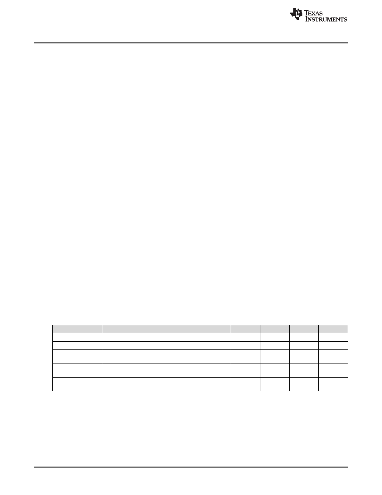
Table 1. Recommended Application Range for DRV10974
Parameter Description MIN TYP MAX Unit
Motor Voltage - 4.4 12 18 V
BEMF Constant (Kt) Phase to center tap. Measured while motor is coasting 5 150 mV/Hz
Motor Phase
Resistance
Motor Winding
Current
Absolute Maximum
Current
Phase to center Tap. Can be derived from dividing
phase-to-phase resistance by two.
During locked condition 2.5 A (Peak)
3 Comprehensive Tuning
The comprehensive tuning section covers the methodology for tuning each resistor value experimentally.
As a result, testing is required to find the optimal resistor value for the motor. This includes replacing the
resistors on the DRV10974 pins, as necessary. As a result, using a DRV10974EVM is highly recommend
for easily replacing resistors on the pins. For more information, see the DRV10974 Evaluation Module
User's Guide.
2
DRV10974 Tuning Guide
Copyright © 2018, Texas Instruments Incorporated
1 20 Ω
1 A (RMS)
SLOU505–April 2018
Submit Documentation Feedback
Page 3
www.ti.com
3.1 Finding Closed-Loop Current and Coasting Time
To choose the correct resistor values, the Closed-Loop Current (I
found.
1. Set ADV to 400 µs (59 kΩ), CS to 1.4 A (115 kΩ), RMP to the slowest setting (7.32 kΩ) which is
mentioned in the previous section. Note these are the default values on the EVM.
NOTE: If the user knows the target supply voltage (VCC) used in the application and the resistance of
the motor, either from the motor data sheet or by measuring the resistance between two
phases (R
), a starting CS resistor value can be obtained from Table 2 and Equation 2.
PH-PH
2. Apply power to the device to spin the motor to the maximum target speed.
3. If the motor fails to spin up reduce the current limit (CS) by one level. Repeat step 3 until the motor
successfully spins up.
4. Record the motor peak phase current during steady-state run (I
• This is used to determine the resistor on the CS pin
5. Provide a command of 0 and measure how long the motor takes to coast to a stop (t
• This is used to determine the resistor on the RMP pin
3.2 Selecting CS Resistor
The CS resistor controls the current limit during the open loop and align phase. Assuming I
captured in the previous section, use the closest value derived from Equation 1 to find an acceptable CS
resistor to set I
LIMIT
:
) and Coasting Time (t
PEAK
).
PEAK
Comprehensive Tuning
) must be
coast
).
coast
was
PEAK
(1)
NOTE: Large resistance motors may result in large I
values (that is, I
LIMIT
values that are larger
LIMIT
than in Table 2). As a result, use Equation 2 instead.
If the user knows the target supply voltage (VCC) used in the application and the resistance of the motor,
either from the motor data sheet or by measuring the resistance between two phases (R
), obtain an
PH-PH
accurate CS resistor value from Equation 2:
(2)
SLOU505–April 2018
Submit Documentation Feedback
Copyright © 2018, Texas Instruments Incorporated
DRV10974 Tuning Guide
3
Page 4
Comprehensive Tuning
Using the current gathered from ICS, select an appropriate RCSusing Table 2.
If the target RPM is slow, or the resistor given is larger than the value experimentally found in Section 3.1,
then the CS may have to be reduced until the motor can start up successfully.
3.3 Selecting ADV Resistor
The ADV pin controls the lead time that the DRV10974 will start driving the motor. The lead time attempts
to align the current applied through motor phases and the Back EMF voltage (BEMF) induced by the
permanent magnets on the rotor passing by the windings on the stator. If the current and the BEMF are
perfectly aligned, efficiency and start-up reliability are drastically increased.
However, tuning the lead time is very experimental and methodical. If the motor starts up reliability and
reaches the target RPM at 100%, then optimal tuning may not be needed.
To tune the lead time, start with the default lead time (400 µs) then:
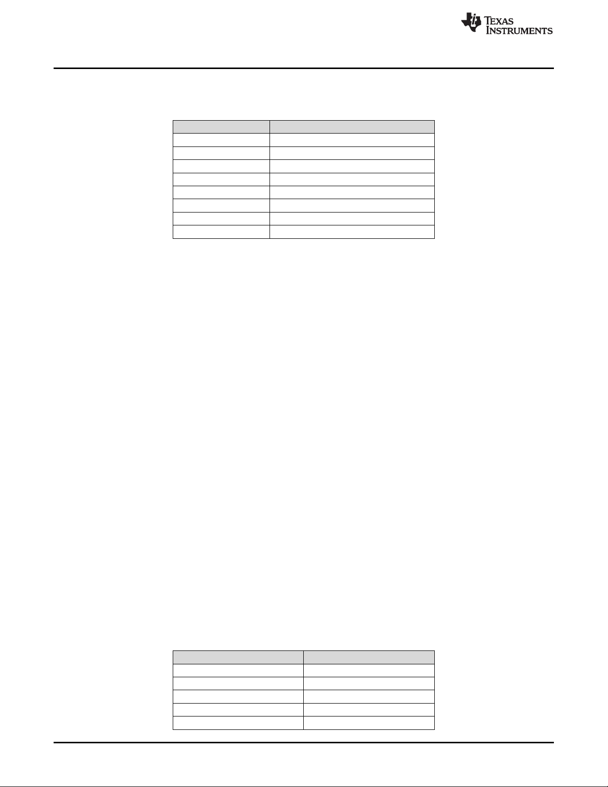
Table 2. CS Resistor Table
R
(kΩ) I
(CS)
7.32 200
16.2 400
25.5 600
38.3 800
54.9 1000
80.6 1200
115 1400
182 1600 (1500 during align and startup)
(LIMIT)
(mA)
www.ti.com
1. Successfully run the motor at 100% speed
2. Record the current consumed by the power supply (ICC)
3. Record the frequency on the FG pin (fFG) which corresponds to the speed
4. Next, calculate the ratio of frequency (speed) over current (fFG/ ICC)
The highest ratio of frequency over current with the highest speed is the most efficient lead time. As a
result, decrease the lead time by one step (that is, lead time = 250 µs) by changing the ADV resistor and
repeat the process.
• If the ratio gets larger with the same speed after decreasing the lead time
– Keep decreasing the lead time until the ratio gets smaller
• If the ratio gets smaller with the same speed after decreasing the lead time
– Increase the lead time instead and see if the ratio gets larger
• If the speed significantly gets smaller after making the lead time larger
– Check previous values.
• Most applications fall within the 100 µs–400 µs range but the ratio and speed will show the best lead
time
• Once ADV is tuned for a specific motor, it does not need to be tuned again
Table 3. ADV Resistor Table
R
(kΩ) Lead Time (µs)
ADV
10.7 10
14.3 25
17.8 50
22.1 100
28 150
4
DRV10974 Tuning Guide
Copyright © 2018, Texas Instruments Incorporated
Submit Documentation Feedback
SLOU505–April 2018
Page 5

www.ti.com
3.4 Selecting RMP Resistor
The RMP resistor controls the acceleration profile used when driving the motor. The acceleration controls
how fast the motor accelerates during open loop using the first- and second-order acceleration coefficients
(ACCEL2 and ACCEL1, respectively), the closed-loop acceleration, and closed-loop deceleration.
Assuming t
Table 4. Using the table, further tests are done to find the final RMP value:
was captured in the previous section, a table of recommended RMP resistors are given in
coast
Table 3. ADV Resistor Table (continued)
R
(kΩ) Lead Time (µs)
ADV
34 200
41.2 250
49.9 300
59 400
71.5 500
86.6 600
105 700
124 800
150 900
182 1000
Comprehensive Tuning
Table 4. RMP Resistor Values for t
t
(s) R
coast
t
< 11 41.2 27 75 0.2 11
coast
11 < t
t
coast
< 22 34 14 50 0.2 22
coast
> 22 22.1 7 25 0.2 44
(kΩ) ACCEL2 (Hz/s2) ACCEL1 (Hz/s) Closed-Loop
RMP
17.8 3.3 25 1 11
28 7 35 0.2 22
14.3 1.65 15 1 22
10.7 1.65 9.2 2.7 22
7.32 0.22 4.6 2.7 44
coast
Acceleration Slew Rate
(s)
Closed-Loop
Deceleration Slew Rate
(s)
To tune RMP:
1. Use Table 4 in combination with the measured t
to determine the range of RMP resistor values that
coast
should be used for this testing.
2. Start with the largest value RMP resistor in the range, which indicates the fastest start up in this range,
and conduct a few steady-state, stop, start tests.
• A steady-state, stop, start test refers to running the motor at a 100% for some time, giving a 0%
speed command to make the motor coast, and then giving a nonzero speed command before the
motor stops coasting. This will be the worst-case start up scenario for the motor
3. If the motor successfully and reliability started up after testing, then select the current value as the
RMP value.
4. If the motor did not successfully and reliability start up after testing, decrease the RMP resistor value in
the appropriate range and repeat the steady-state start, stop tests.
a. If every resistor in the current t
range does not work, use a lower t
coast
range and repeat the
coast
process.
b. In addition, reducing the CS value may help increase start up reliability.
SLOU505–April 2018
Submit Documentation Feedback
Copyright © 2018, Texas Instruments Incorporated
DRV10974 Tuning Guide
5
Page 6

Comprehensive Tuning
NOTE: Higher closed-loop acceleration variants are available for each setting in Table 4, consult
Table 5 for more information.
www.ti.com
Table 5. RMP Resistor Table
RMP
Selection
0 7.32 0.22 4.6 2.7 44
1 10.7 1.65 9.2 2.7 22
2 14.3 1.65 15 1 22
3 17.8 3.3 25 1 11
4 22.1 7 25 0.2 44
5 28 7 35 0.2 22
6 34 14 50 0.2 22
7 41.2 27 75 0.2 11
8 49.9 27 75 5.4 11
9 59 14 50 8 22
10 71.5 7 35 11 22
11 86.6 7 25 22 44
12 105 3.3 25 5.4 11
13 124 1.65 15 8 22
14 150 1.65 9.2 11 22
15 182 0.22 4.2 22 44
R
(kΩ) ACCEL2 (Hz/s2) ACCEL1 (Hz/s) Closed-Loop
RMP
3.5 Example CS, ADV, and RMP Resistor Tuning
This section goes over an example scenario and the steps taken to tune each resistor for the CS, ADV,
and RMP settings.
An example motor application has the following parameters:
• VCC= 12 V
• Target RPM = 1500 RPM
• Motor Pole Pairs = 4 pairs
Acceleration Transition
Time (s)
Closed-Loop
Deceleration Transition
Time (s)
3.5.1 Example Closed-Loop Current and Coasting Time
While the motor was able to start up with the default resistor settings using the DRV10974EVM, some
optimization is needed. As a result, I
6
DRV10974 Tuning Guide
Copyright © 2018, Texas Instruments Incorporated
PEAK
and t
need to be measured.
coast
Submit Documentation Feedback
SLOU505–April 2018
Page 7

www.ti.com
Comprehensive Tuning
Figure 1. Example Peak Current in Closed Loop
As Figure 1 shows, the peak current can be roughly calculated as 375 mA. This is used when calculating
the CS resistor.
(3)
As Figure 2 shows, the DRV10974 stops driving the motor after driving it at 100% speed, and the coasting
time, t
SLOU505–April 2018
Submit Documentation Feedback
coast
= 11 s.
Figure 2. Example Coasting Time
Copyright © 2018, Texas Instruments Incorporated
DRV10974 Tuning Guide
7
Page 8

Comprehensive Tuning
3.5.2 Example CS Resistor Selection
Since I
= 325 mA and the motor will be used in a 12-V application, a CS resistor value is found using
PEAK
Equation 4:
Unfortunately, 1.5 A is not a valid current limit value according to CS Resistor Table 2. As a result, the
alternative method is used.
Using a DMM, the resistance between any of the 2 phases of a 3-Phase BLDC motor (R
determined to be 17 Ω. Using Equation 2, a general CS resistor value is chosen to be RCS= 25.5 kΩ,
corresponding 600 mA of current limiting according to Table 2.
By populating the resistor, the motor is still able to spin up reliably and enter closed loop.
3.5.3 Example ADV Resistor Selection
To find the correct ADV resistor, the highest ratio of speed over supply current (fFG/ ICC) with the highest
speed must be found. By creating Table 6, the ratio and speed can be easily visualized.
PH-PH
www.ti.com
(4)
) was
(5)
Table 6. Experimental Supply Current, Speed, and Speed/Current Ratio With Different Lead Times
Lead Time (µs) ICC(A) fFG(Hz) fFG/ ICC(Hz/A)
25 0.310 108.7 350.6
50 0.310 108.7 350.6
100 0.300 108.7 362.3
200 0.299 108.2 361.9
300 0.298 107.2 359.7
400 0.293 106.4 363.1
500 0.293 105.5 360.0
As Table 6 shows, the highest ratio with the highest speed corresponds to lead time = 100 µs. This
corresponds to the resistor value for R
While the 400 µs gave the highest ratio of speed over current, the actual speed (fFG) dropped 2% (108.7
Hz to 107.2 Hz). This makes 400 µs less optimal than 100 µs for the lead time.
3.5.4 Example RMP Resistor Selection
Since t
coast
= 11 s, t
falls between the 11 s and 22 s range in the RMP selection (R
coast
and 10.7 kΩ), the 34-kΩ resistor is populated and a steady-state, stop, start test is conducted. The 34-kΩ
resistor is used because it is the fastest RMP rate in this range.
= 22 kΩ in Table 3.
ADV
= 34, 28, 14.3,
RMP
8
DRV10974 Tuning Guide
Copyright © 2018, Texas Instruments Incorporated
Submit Documentation Feedback
SLOU505–April 2018
Page 9

www.ti.com
Comprehensive Tuning
Figure 3. Example Unsuccessful Steady-State, Stop, Start Test
As Figure 3 shows, the hand off from open loop to closed loop was unsuccessful and the DRV10974
stopped driving the motor for protection. Since this test was not successful, the next largest resistor (28
kΩ) was tested.
Figure 4. Example Successful Steady-State, Stop, Start Test
As Figure 4 shows, the hand off from open loop to closed loop was successful and the motor is driven to
100% speed. As a result, the resistor value is chosen to be R
open-loop acceleration, closed-loop acceleration, and closed-loop deceleration as shown in Table 5.
SLOU505–April 2018
Submit Documentation Feedback
= 28 kΩ. The corresponding settings for
RMP
Copyright © 2018, Texas Instruments Incorporated
DRV10974 Tuning Guide
9
Page 10

Comprehensive Tuning
3.5.5 Summary and Results
Using the tuning method, the following resistors were selected:
• RCS= 25.5 kΩ for a current limit of 600 mA
• R
• R
= 22 kΩ for a lead time of 100 µs
ADV
= 28 kΩ for a RMP code of 5
RMP
The RPM of the motor is calculated by using Equation 6:
Using the number of pole pairs and the speed from the lead time tuning for the ADV resistor, the RPM of
the motor is calculated to be above the target RPM of 1500 RPM.
www.ti.com
(6)
10
DRV10974 Tuning Guide
Copyright © 2018, Texas Instruments Incorporated
Submit Documentation Feedback
SLOU505–April 2018
Page 11

IMPORTANT NOTICE FOR TI DESIGN INFORMATION AND RESOURCES
Texas Instruments Incorporated (‘TI”) technical, application or other design advice, services or information, including, but not limited to,
reference designs and materials relating to evaluation modules, (collectively, “TI Resources”) are intended to assist designers who are
developing applications that incorporate TI products; by downloading, accessing or using any particular TI Resource in any way, you
(individually or, if you are acting on behalf of a company, your company) agree to use it solely for this purpose and subject to the terms of
this Notice.
TI’s provision of TI Resources does not expand or otherwise alter TI’s applicable published warranties or warranty disclaimers for TI
products, and no additional obligations or liabilities arise from TI providing such TI Resources. TI reserves the right to make corrections,
enhancements, improvements and other changes to its TI Resources.
You understand and agree that you remain responsible for using your independent analysis, evaluation and judgment in designing your
applications and that you have full and exclusive responsibility to assure the safety of your applications and compliance of your applications
(and of all TI products used in or for your applications) with all applicable regulations, laws and other applicable requirements. You
represent that, with respect to your applications, you have all the necessary expertise to create and implement safeguards that (1)
anticipate dangerous consequences of failures, (2) monitor failures and their consequences, and (3) lessen the likelihood of failures that
might cause harm and take appropriate actions. You agree that prior to using or distributing any applications that include TI products, you
will thoroughly test such applications and the functionality of such TI products as used in such applications. TI has not conducted any
testing other than that specifically described in the published documentation for a particular TI Resource.
You are authorized to use, copy and modify any individual TI Resource only in connection with the development of applications that include
the TI product(s) identified in such TI Resource. NO OTHER LICENSE, EXPRESS OR IMPLIED, BY ESTOPPEL OR OTHERWISE TO
ANY OTHER TI INTELLECTUAL PROPERTY RIGHT, AND NO LICENSE TO ANY TECHNOLOGY OR INTELLECTUAL PROPERTY
RIGHT OF TI OR ANY THIRD PARTY IS GRANTED HEREIN, including but not limited to any patent right, copyright, mask work right, or
other intellectual property right relating to any combination, machine, or process in which TI products or services are used. Information
regarding or referencing third-party products or services does not constitute a license to use such products or services, or a warranty or
endorsement thereof. Use of TI Resources may require a license from a third party under the patents or other intellectual property of the
third party, or a license from TI under the patents or other intellectual property of TI.
TI RESOURCES ARE PROVIDED “AS IS” AND WITH ALL FAULTS. TI DISCLAIMS ALL OTHER WARRANTIES OR
REPRESENTATIONS, EXPRESS OR IMPLIED, REGARDING TI RESOURCES OR USE THEREOF, INCLUDING BUT NOT LIMITED TO
ACCURACY OR COMPLETENESS, TITLE, ANY EPIDEMIC FAILURE WARRANTY AND ANY IMPLIED WARRANTIES OF
MERCHANTABILITY, FITNESS FOR A PARTICULAR PURPOSE, AND NON-INFRINGEMENT OF ANY THIRD PARTY INTELLECTUAL
PROPERTY RIGHTS.
TI SHALL NOT BE LIABLE FOR AND SHALL NOT DEFEND OR INDEMNIFY YOU AGAINST ANY CLAIM, INCLUDING BUT NOT
LIMITED TO ANY INFRINGEMENT CLAIM THAT RELATES TO OR IS BASED ON ANY COMBINATION OF PRODUCTS EVEN IF
DESCRIBED IN TI RESOURCES OR OTHERWISE. IN NO EVENT SHALL TI BE LIABLE FOR ANY ACTUAL, DIRECT, SPECIAL,
COLLATERAL, INDIRECT, PUNITIVE, INCIDENTAL, CONSEQUENTIAL OR EXEMPLARY DAMAGES IN CONNECTION WITH OR
ARISING OUT OF TI RESOURCES OR USE THEREOF, AND REGARDLESS OF WHETHER TI HAS BEEN ADVISED OF THE
POSSIBILITY OF SUCH DAMAGES.
You agree to fully indemnify TI and its representatives against any damages, costs, losses, and/or liabilities arising out of your noncompliance with the terms and provisions of this Notice.
This Notice applies to TI Resources. Additional terms apply to the use and purchase of certain types of materials, TI products and services.
These include; without limitation, TI’s standard terms for semiconductor products http://www.ti.com/sc/docs/stdterms.htm), evaluation
modules, and samples (http://www.ti.com/sc/docs/sampterms.htm).
Mailing Address: Texas Instruments, Post Office Box 655303, Dallas, Texas 75265
Copyright © 2018, Texas Instruments Incorporated
 Loading...