

Page 1

User's Guide
DLPU096–November 2019
DLP5534Q1EVM Evaluation Module User's Guide
The DLP5534Q1 Evaluation Module (EVM) is a complete electronic subsystem designed to drive the
DLP5534-Q1 chipset. The DLP5534-Q1 chipset consists of the DLP5534-Q1, the DLPC230-Q1, and the
TPS99000-Q1. When combined with illumination and projection optics, 405 nm and other LEDs this EVM
can be used to develop an automotive grade projector for applications such as transparent window display
utilizing phosphor film(s) embedded in a window.
Except for the DMD, there are no optical elements provided with this EVM. It is expected that this EVM is
procured in order to mount to a custom designed projector.
The DLP5534Q1 EVM is not a production design. It is intended for evaluation only.
Contents
1 User Guide Overview........................................................................................................ 2
1.1 What is in the DLP5534Q1 EVM ................................................................................. 2
1.2 Specifications........................................................................................................ 7
2 Quick Start.................................................................................................................... 9
2.1 Kit Assembly Instructions .......................................................................................... 9
2.2 Software Installation .............................................................................................. 10
2.3 Powering-Up EVM................................................................................................. 10
2.4 Connecting EVM to the DLPC230-Q1 Control Program ..................................................... 10
2.5 Steps to Reprogram the Onboard Flash Memory............................................................. 11
3 Optic Engine Requirements............................................................................................... 11
1 EVM Controller PCB ........................................................................................................ 2
2 EVM Illumination Driver PCB............................................................................................... 4
3 EVM Cables .................................................................................................................. 6
4 EVM Cable Connections.................................................................................................... 9
5 Connecting to the DLPC230-Q1 Using the DLPC230-Q1 Automotive Control Program ......................... 10
6 DLPC230-Q1 Automotive Control Program Communication Settings............................................... 11
1 Controller PCB Ports ........................................................................................................ 3
2 Controller LED Indicators ................................................................................................... 3
3 Controller PCB Switches.................................................................................................... 3
4 Illumination Driver PCB Ports.............................................................................................. 5
5 EVM Cables .................................................................................................................. 6
6 Electrical Specifications..................................................................................................... 7
7 EVM PCB Components Which are Not Rated for –40°C to 105°C ................................................... 7
Trademarks
All trademarks are the property of their respective owners.
List of Figures
List of Tables
DLPU096–November 2019
Submit Documentation Feedback
DLP5534Q1EVM Evaluation Module User's Guide
Copyright © 2019, Texas Instruments Incorporated
1
Page 2
User Guide Overview
1 User Guide Overview
This user's guide presents an overview and general description of the DLP5534Q1 EVM and provides first
steps for getting started using the EVM.
1.1 What is in the DLP5534Q1 EVM
The DLP5534Q1 electronics EVM consists of a Controller PCB, an Illumination Driver PCB, cables, and a
USB to SPI adapter.
1.1.1 Controller PCB
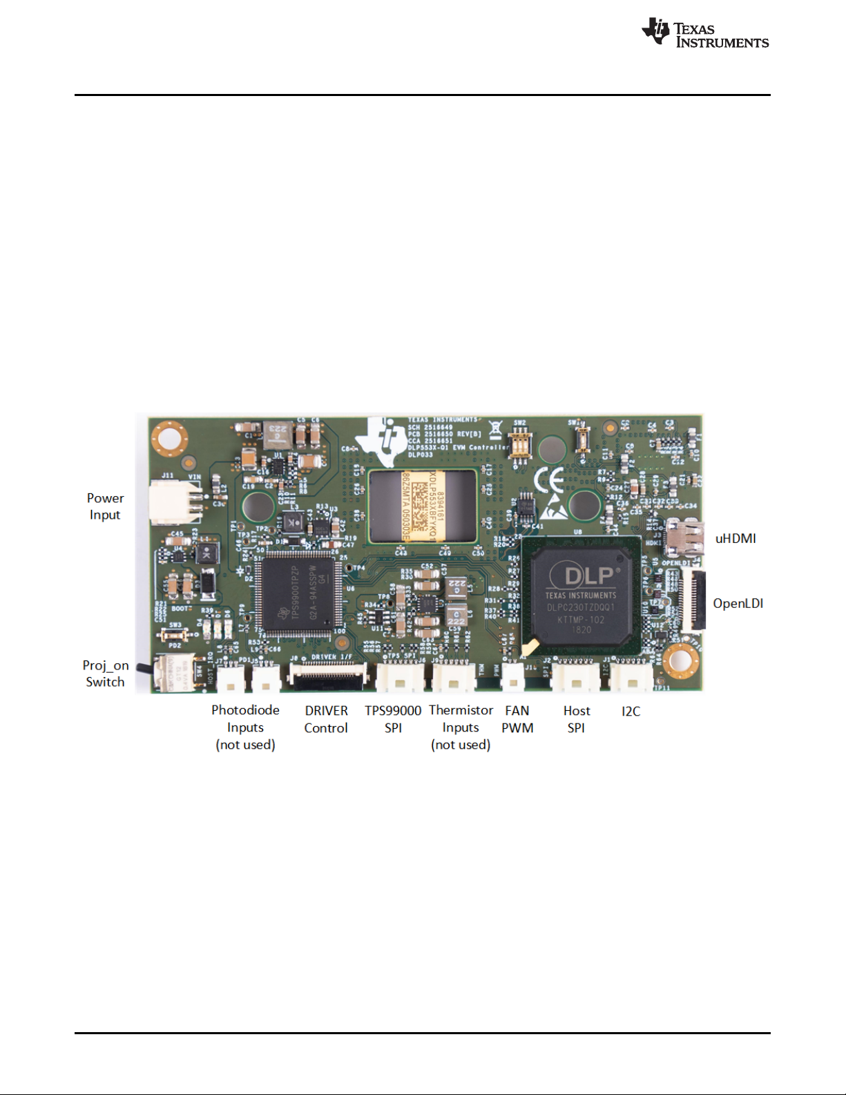
The Controller PCB shown in Figure 1 includes the DLP5534-Q1 DMD, the DLPC230-Q1 DMD Controller,
and the TPS99000-Q1. It supports video inputs from either a micro HDMI or OpenLDI interface and
provides the formatting and control to display the video on the DLP5534-Q1 DMD. The EVM can be
controlled with either an SPI or I2C interface. The SPI or I2C interface can also be used to reprogram the
serial Flash that is used to store DLPC230-Q1 software and configuration. An optional second SPI port is
provided for monitoring the TPS99000-Q1. The EVM includes a flex interface to control the Illumination
Driver PCB. The EVM has external photodiode inputs and thermistor inputs which are not used for this
application.
www.ti.com
The Controller PCB contains the ports listed in Table 1. Indicator LEDs are listed in Table 2.
2
DLP5534Q1EVM Evaluation Module User's Guide
Figure 1. EVM Controller PCB
DLPU096–November 2019
Submit Documentation Feedback
Copyright © 2019, Texas Instruments Incorporated
Page 3

www.ti.com
Table 1. Controller PCB Ports
SCHEMATIC REFERENCE FUNCTION
J1 Host I2C, PROJ_ON, HOLD_BOOT, HOST_IRQ
J2 Host SPI
J3 Micro HDMI
J4 OpenLDI (Flex connector)
J5 Photodiode 1
J6 TPS99000-Q1 SPI Debug
J7 Photodiode 2
J8 LED Driver Interface
J9 LED Thermistor
J10 Fan PWM output (optional)
J11 Controller Power
(1)
Port unused for this application. Cable not provided.
(1)
(1)
(1)
Table 2. Controller LED Indicators
SCHEMATIC REFERENCE FUNCTION
D4 (Green)
D5 (Green)
D6 (Red)
Input power to Controller (from Illumination Driver)
Off: No power connected
On: Power connected
PROJ_ON
Off: System Off
On: System On
HOST_IRQ
Off: Interrupt not asserted
On: Interrupt asserted
User Guide Overview
The Controller PCB switches are listed in Table 3. SW4 is a toggle switch for PROJ_ON which is used to
turn on and off the electronics. Note that parts of the board are still powered when PROJ_ON is in the off
position. SW1, SW2, and SW3 are dip switches that control the states of configuration signals the
DLPC230-Q1 reads when it comes out of reset. These switches should be set based on the desired
configuration options.
Table 3. Controller PCB Switches
SCHEMATIC REFERENCE /
SIGNAL NUMBER
SW1 (1)
SW2 (1)
SW2 (2)
SW2 (3)
SW3
SW4
FUNCTION
Spread Spectrum Enable
Off: Disabled
On: Enabled
Host Port Checksum Select
Off: CRC
On: Checksum
Host Interface Select
Off: Host SPI
On: Host I2C
Host SPI Mode
Off: Mode 0 or 3
On: Mode 1 or 2
Hold in Boot
Off: Do not hold in boot (continue to main application)
On: Hold in boot
PROJ_ON
Off: Turn off system
On: Turn on system
On state is toward the closest corner of the board Figure 1
DLPU096–November 2019
Submit Documentation Feedback
DLP5534Q1EVM Evaluation Module User's Guide
Copyright © 2019, Texas Instruments Incorporated
3
Page 4
User Guide Overview
1.1.2 Illumination Driver PCB
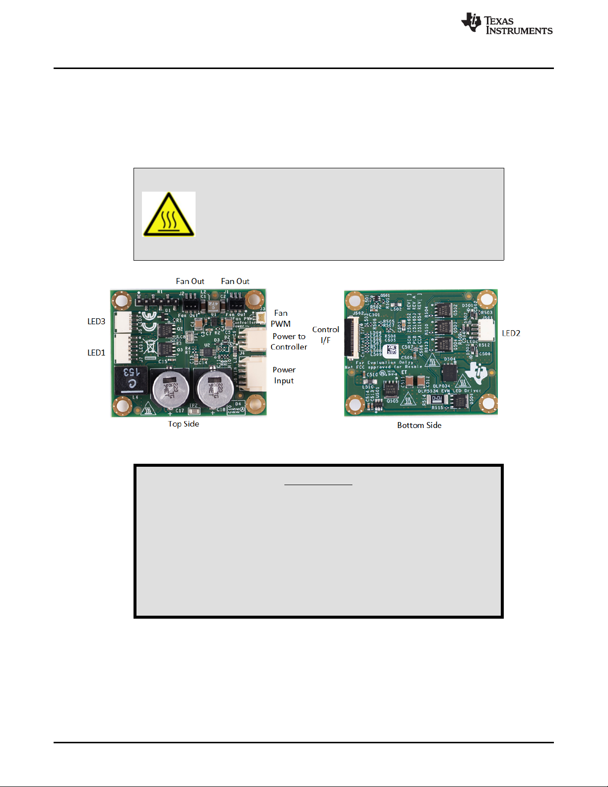
The Illumination Driver PCB shown in Figure 2 is controlled by the Controller PCB over a flex cable.
Power can be input to the Illumination Driver from a lab supply. The Illumination driver provides reverse
bias protection and supplies power to the Controller PCB over a separate cable. The Illumination Driver
has outputs for one to three illuminators. These are typically LEDs, but it is possible other illuminators
could be used. See Section 1.2.1 for input and output specifications of the EVM. Depending on operating
conditions, some parts and surfaces of the PCB can be hot.
Hot surface. Contact may cause burns. Do not touch!
www.ti.com
CAUTION
Figure 2. EVM Illumination Driver PCB
WARNING
When choosing your LED component (not included with this EVM)
the end user must consult the LED data sheet supplied by the LED
manufacturer to identify the EN62471 Risk Group Rating and
review any potential eye hazards associated with the LED chosen.
Always consider and implement the use of effective light filtering
and darkening protective eyewear and be fully aware of
surrounding laboratory-type set-ups when viewing intense light
sources that may be required to minimize or eliminate such risks in
order to avoid accidents related to temporary blindness.
The Illumination Driver PCB contains the ports listed in Table 4.
4
DLP5534Q1EVM Evaluation Module User's Guide
DLPU096–November 2019
Submit Documentation Feedback
Copyright © 2019, Texas Instruments Incorporated
Page 5

www.ti.com
Table 4. Illumination Driver PCB Ports
SCHEMATIC REFERENCE FUNCTION
J1 Fan Output
J2 Fan Output
J3 Fan PWM Input
J5 LED3 Illuminator Output
J6 Controller Power
J7 LED1 Illumination Output
J8 Input Power
J501 LED2 Illumination Output
J502 Controller to Driver Control Interface
User Guide Overview
DLPU096–November 2019
Submit Documentation Feedback
DLP5534Q1EVM Evaluation Module User's Guide
Copyright © 2019, Texas Instruments Incorporated
5
Page 6

User Guide Overview
1.1.3 EVM Cables
The EVM cables and Cheetah USB to SPI adapter are listed in Table 5 and shown in Figure 3.
www.ti.com
Figure 3. EVM Cables
Table 5. EVM Cables
NAME REFERENCE QUANTITY
Cheetah™ SPI Host Adapter A 1
Host SPI Cable B 1
Host I2C Cable
(Includes PROJ_ON, HOLD_BOOT, HOST_IRQ signals)
Driver to Controller Power Cable D 1
Input Power Cable E 1
LED1 Illuminator Power Cable F 1
LED2 Illuminator Power Cable G 1
LED3 Illuminator Power Cable H 1
Fan PWM I 1
Controller to Driver Control Flex J 1
OpenLDI Flex Cable K 1
Micro HDMI Cable L 1
C 1
6
DLP5534Q1EVM Evaluation Module User's Guide
Copyright © 2019, Texas Instruments Incorporated
DLPU096–November 2019
Submit Documentation Feedback
Page 7

www.ti.com
1.2 Specifications
1.2.1 Electrical Specifications
PARAMETER MIN NOM MAX UNIT
Input
Voltage
(Input voltage must be higher than forward voltage of LED)
Illumination Driver Output Load
Voltage
(Per LED Color Output)
Current
(Per LED Color Output)
Fan Output
Voltage 5 V
Current (total for all fans) 1 A
Temperature
Operating DMD Temperature
(1)
Care must be taken to ensure that individual components and PCB do not exceed their maximum temperature when driving
high-power load. Force air cooling might be required to operate at high output current, high input voltage, and/or high duty
cycles.
(2)
Some components are only rated to 85°C. Refer to Table 7 for a list of these components.
(1)
Table 6. Electrical Specifications
–40 105
User Guide Overview
8 12 18 V
9 V
4 A RMS
(2)
°C
1.2.2 Component Temperature Ratings
The PCB materials and most of the PCB components are rated to operate between –40°C to 105°C,
including the DLP5534-Q1, the DLPC230-Q1, and the TPS99000-Q1.
Some components on PCBs, such as switches, connectors, and indicator LEDs, do not meet this
temperature rating. The specifications for EVM components which are not rated between –40°C to 105°C
are listed in Table 7. Please refer to the EVM bill of materials to review the temperature specifications of
all components used in the EVM design.
Table 7. EVM PCB Components Which are Not Rated for –40°C to 105°C
Board Reference Part Number Manufacturer Description
Controller D4, D5 LTST-C171KGKT Lite-On LED, GREEN 0805 –55 85
Controller D6 LTST-C171KRKT Lite-On LED, RED 0805 –55 85
Controller J3 685119248123 Wurth
Controller SW2 CVS-03TB Copal Electronics Inc
Controller SW1,SW3 CVS-01TB Copal Electronics Inc
Controller SW4 GT12MSABETR C&K Comp SWITCH, SPST, GULL –30 85
Controller
Controller U501 TFP401AIPZPRQ1 Texas Instruments
U5, U7,
U10, U503,
U504
PCMF2HDMI2SZ Nexperia
CONN MICRO HDMI
RIGHT ANGLE
SWITCH DIP SLIDE 3-
POS 1 MM 6 V
SWITCH DIP SLIDE 1-
POS 1 MM 6 V
COMMON MODE
CHOKE 4LN SMD ESD
IC PANELBUS DVI
RCVR 100-HTQFP
Temperature
Minimum (°C)
–40 85
–40 85
–40 85
–40 85
–40 85
Temperature
Maximum (°C)
The Controller and Illumination Driver PCBs have a UL flame rating of 130°C maximum.
DLPU096–November 2019
Submit Documentation Feedback
DLP5534Q1EVM Evaluation Module User's Guide
Copyright © 2019, Texas Instruments Incorporated
7
Page 8

User Guide Overview
1.2.3 Input Video Specifications
The following input video resolutions are supported on the HDMI and OpenLDI interfaces. These input
video resolutions are programmed in the Extended Display Identification Data (EDID) EEPROM for the
EVM's HDMI interface allowing a connected computer to read the supported resolutions and timing. Note
that some computers may not be able to output all of these resolutions, in particular 576 × 288.
• 1152 × 1152
• 1152 × 576
• 576 × 288
The recommended input source timings for the EVM's HDMI interface are specified in the DLPC230-Q1
data sheet. These timing parameters are also recommended for the OpenLDI interface.
1.2.4 SPI and I2C Timing
For more information on SPI and I2C specifications, see the DLPC230-Q1 data sheet.
www.ti.com
8
DLP5534Q1EVM Evaluation Module User's Guide
Copyright © 2019, Texas Instruments Incorporated
DLPU096–November 2019
Submit Documentation Feedback
Page 9

www.ti.com
2 Quick Start
Use the following instructions to setup your DLP5534Q1 EVM and PC.
2.1 Kit Assembly Instructions
A diagram of all the EVM cable connections is shown in Figure 4.
1. Connect the Controller to Driver control Interface flex to the Controller PCB (J8) and the Illumination
Driver PCB (J502).
2. Connect the Host SPI cable to the Controller PCB (J2) and the Cheetah adapter. Connect the Cheetah
adapter’s USB cable to PC.
3. Connect the Controller Power cable to the Controller PCB (J11) and the Illumination Driver PCB (J6).
4. Connect the LED 1 Illumination output cable to the Illumination Driver PCB (J7) to the LED 1
illuminator in the optics engine.
5. If there is a second illuminator connect the LED 2 Illumination output cable to the Illumination Driver
PCB (J501) to the LED 2 illuminator in the optics.
6. If there is a third illuminator connect the LED 3 Illumination output cable to the Illumination Driver PCB
(J5) to the LED 3 illuminator in the optics engine.
7. Connect the Micro HDMI cable to the Controller Board (J3). Connect the Micro HDMI cable to PC
HDMI port.
8. Connect the Power Input cable to the Illumination Driver Board (J8).
9. If there are fans connect them to LED Driver Board (J1 and J2).
10. If fan PWM is utilized then connect the Fan PWM cable from controller (J10) to LED Driver (J3).
Quick Start
DLPU096–November 2019
Submit Documentation Feedback
Figure 4. EVM Cable Connections
DLP5534Q1EVM Evaluation Module User's Guide
Copyright © 2019, Texas Instruments Incorporated
9
Page 10

Quick Start
2.2 Software Installation
1. Install the DLPC230-Q1 Control Program (http://www.ti.com/mysecuresoftware).
2. Install Total Phase Cheetah USB adapter drivers (https://www.totalphase.com/products/usb-drivers-
windows).
2.3 Powering-Up EVM
1. Connect input power cable to a power supply that meets input power specifications defined in Table 6.
The red wire is the V+ terminal and black wire is the V– terminal.
2. Turn on the supply power. Once powered up, a Controller PCB LED indicator (D4) should illuminate
green.
3. Turn the PROJ_ON switch (SW4) ON. The ON position is towards the closest corner of the board. A
Controller PCB LED indicator (D5) should illuminate green. It is also acceptable to leave the PROJ_ON
switch in the ON position when powering on and off.
2.4 Connecting EVM to the DLPC230-Q1 Control Program
1. Start the DLPC230-Q1 Control Program.
2. On the connection page set the DLPC230-Q1 Host to SPI and select the Cheetah from the drop down
menu (see Figure 5). Note that the Cheetah must be connected to computer with USB cable for it to
show up in the drop down box.
www.ti.com
Figure 5. Connecting to the DLPC230-Q1 Using the DLPC230-Q1 Automotive Control Program
10
DLP5534Q1EVM Evaluation Module User's Guide
Copyright © 2019, Texas Instruments Incorporated
DLPU096–November 2019
Submit Documentation Feedback
Page 11

www.ti.com
3. Select "Connection Settings" to confirm the SPI configuration shown in Figure 6 matches the Controller
Quick Start
PCB switch settings described in Table 3. Specifically, SPI mode and CRC/Checksum may vary based
on switch settings. Press "OK" once configuration is complete.
Figure 6. DLPC230-Q1 Automotive Control Program Communication Settings
4. Click the Connect button. The green circle next to the Connect button should then light up to indicate
that connection was successful to the Cheetah Adapter.
2.5 Steps to Reprogram the Onboard Flash Memory
The DLP5534Q1 EVM comes with onboard serial Flash that is pre-programed with software and basic
configuration. The software and configuration can be updated by reprogramming the serial Flash with the
DLPC230-Q1 Automotive Control Program. Steps to re-program the serial Flash are listed below.
1. Using the DLPC230-Q1 Automotive Control Program, which is connected to the EVM, navigate to the
"Flash Program" tab.
2. Using the folder icon, select an Image File (.bin) and open it.
3. Click "Program and Verify Flash Memory."
Note that if the device is in Display mode, it will automatically be switched to Standby during programming.
3 Optic Engine Requirements
The DLP5534Q1 EVM can be coupled to an optical engine (not included) and phosphor film (not included)
to implement a transparent window display function. The detailed requirements of the optical engine are
beyond the scope of this document, but the optical engine should have a 405 nm illuminator. Other
illuminators above 405 nm are also possible. A heatsink for the DLP5534-Q1 DMD might be needed for
operation in high temperature ambient environments, but is not included in the DLP5534Q1 Electronics
EVM.
DLPU096–November 2019
Submit Documentation Feedback
DLP5534Q1EVM Evaluation Module User's Guide
Copyright © 2019, Texas Instruments Incorporated
11
Page 12

IMPORTANT NOTICE AND DISCLAIMER
TI PROVIDES TECHNICAL AND RELIABILITY DATA (INCLUDING DATASHEETS), DESIGN RESOURCES (INCLUDING REFERENCE
DESIGNS), APPLICATION OR OTHER DESIGN ADVICE, WEB TOOLS, SAFETY INFORMATION, AND OTHER RESOURCES “AS IS”
AND WITH ALL FAULTS, AND DISCLAIMS ALL WARRANTIES, EXPRESS AND IMPLIED, INCLUDING WITHOUT LIMITATION ANY
IMPLIED WARRANTIES OF MERCHANTABILITY, FITNESS FOR A PARTICULAR PURPOSE OR NON-INFRINGEMENT OF THIRD
PARTY INTELLECTUAL PROPERTY RIGHTS.
These resources are intended for skilled developers designing with TI products. You are solely responsible for (1) selecting the appropriate
TI products for your application, (2) designing, validating and testing your application, and (3) ensuring your application meets applicable
standards, and any other safety, security, or other requirements. These resources are subject to change without notice. TI grants you
permission to use these resources only for development of an application that uses the TI products described in the resource. Other
reproduction and display of these resources is prohibited. No license is granted to any other TI intellectual property right or to any third
party intellectual property right. TI disclaims responsibility for, and you will fully indemnify TI and its representatives against, any claims,
damages, costs, losses, and liabilities arising out of your use of these resources.
TI’s products are provided subject to TI’s Terms of Sale (www.ti.com/legal/termsofsale.html) or other applicable terms available either on
ti.com or provided in conjunction with such TI products. TI’s provision of these resources does not expand or otherwise alter TI’s applicable
warranties or warranty disclaimers for TI products.
Mailing Address: Texas Instruments, Post Office Box 655303, Dallas, Texas 75265
Copyright © 2019, Texas Instruments Incorporated
 Loading...