

Page 1
查询DEM-DAI1742供应商
www.ti.com
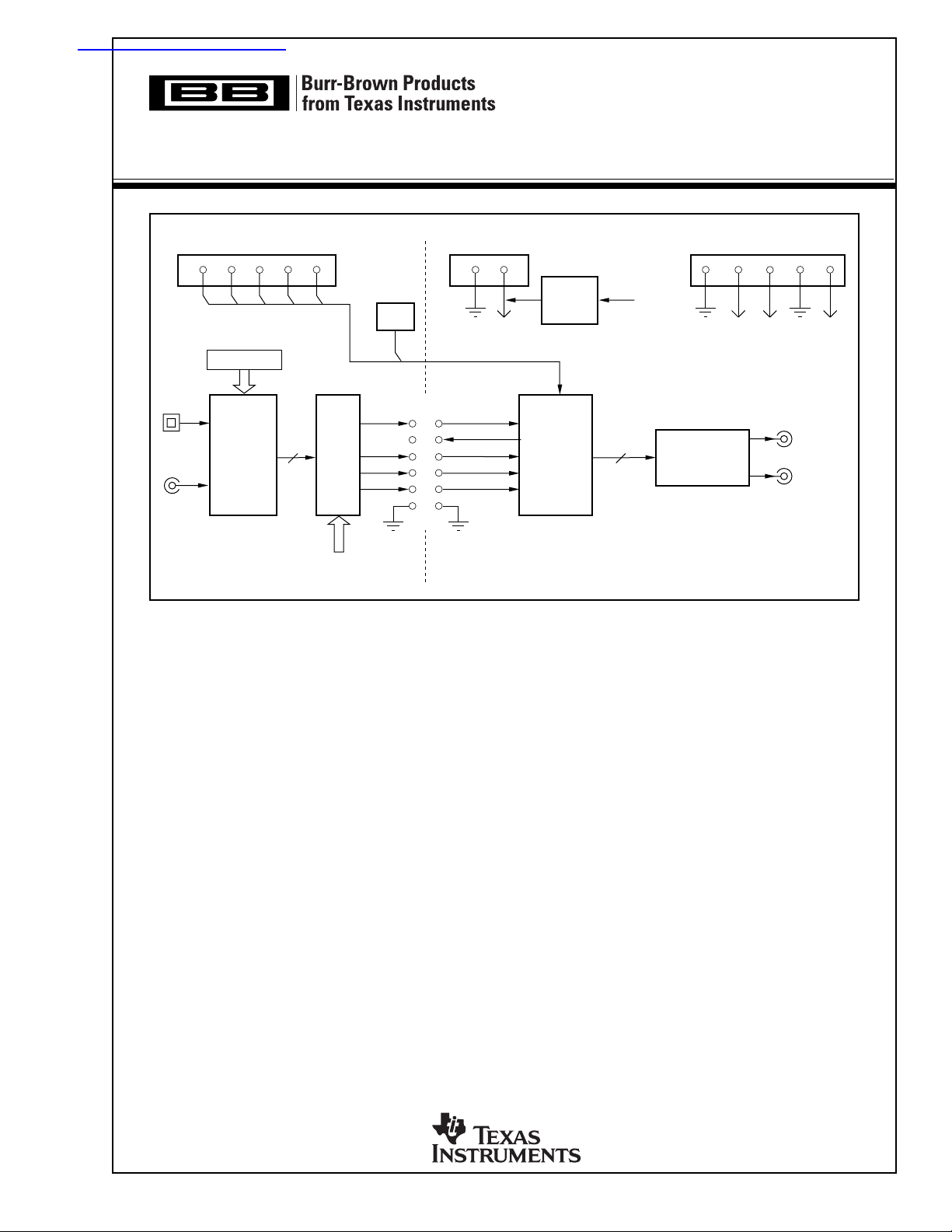
DEM-DAI1742
EVALUATION FIXTURE
VCCAVCC–AVCC+
DD
GND GNDML MC MDI RST MDO GND +V
SW006
Format Control
M2, M1, M0
Opt
Coax
Digital
Audio
Receiver
DAI
(BUS)
Select
External I/F
(CN004)
JUMPER
CLKO
LRCK
DATA
FEATURES
● COMPLETE EVALUATION PLATFORM FOR
THE PCM1742 STEREO AUDIO DAC
● ONBOARD LOW-PASS FILTERS FOR THE
LEFT AND RIGHT CHANNELS
● EASY CONFIGURATION USING ONBOARD
SWITCHES AND JUMPERS
● 96kHz DIGITAL AUDIO RECEIVER ACCEPTS
S/PDIF AND OPTICAL INPUTS
● DEMONSTRATION SOFTWARE FOR
PROGRAMMING THE PCM1742’S INTERNAL
REGISTERS (REQUIRES A PC RUNNING
MICROSOFT WINDOWS® 3.1, 95, 98)
● CENTRONICS CONNECTOR FOR
INTERFACING TO A PC PARALLEL PORT
(REQUIRED FOR THE DEMONSTRATION
SOFTWARE)
SCKI
BCK
3.3V
Regulator
PCM1742
L/R Ch
V
CC
2nd-Order LPF
OPA2134
● POWER-SUPPLY REQUIREMENTS: +5V,
+15V, AND –15V
● CONNECTOR FOR OPTIONAL EXTERNAL
+3.3V POWER SUPPLY
Windows is a registered trademark of Microsoft Corp.
DESCRIPTION
The DEM-DAI1742 is a complete evaluation platform for the PCM1742 24-bit, 192kHz stereo audio
Digital-to-Analog Converter (DAC). All necessary
connectors and circuitry are provided for interfacing
to audio test systems and commercial audio equipment.
L-Channel
R-Channel
Copyright © 2001, Texas Instruments Incorporated SBAU034 Printed in U.S.A. January, 2001
Page 2
HARDWARE DESCRIPTION
POWER SUPPLIES
The DEM-DAI1742 evaluation fixture requires three power
supplies for operating the PCM1742, the digital support
circuitry, and the low-pass filter op amp. Standard banana
jacks are provided for all power-supply connections.
Connector CN054 provides the +5V supply required for
VCC. It is used to power the analog sections of the PCM1742,
as well as the digital audio receiver (U002) and associated
logic (U003 and U004).
Connectors CN051 (AVCC+) and CN053 (AVCC–) are used
to power the OPA2134 dual op amp (U101) that performs
the DAC output low-pass filter function. AVCC+ may be set
from +5V to +18V, while AVCC– may be set from –5V
to –18V.
Ground connections are made at connectors CN052 and
CN055. Both are connected to the ground plane of the DEMDAI1742 board.
In addition to the three required external power supplies, a
+3.3V supply is required for the PCM1742. The +3.3V
supply is typically derived from VCC using an onboard linear
regulator, the REG1117-3.3 (U051). A jumper must be
installed at CN057 to connect the regulator output to the
PCM1742.
A connector (CN056) is provided for connection to an
optional external +3.3V power supply. When using CN056,
the jumper at CN057 must be removed in order to disable the
regulator output.
ANALOG OUTPUTS
The left and right audio outputs are available at RCA jacks
CN104 and CN105 respectively. The outputs are taken from
the low-pass filter, which has a gain of 2. The low-pass filter
may be configured for one of two cutoff frequencies: 54kHz
or 108kHz. Typically, the 54kHz cutoff frequency is used
for all measurements.
For f
installed.
For fbe removed.
ZERO-FLAG OUTPUTS
The zero flags for the left and right channels are brought out
at connector CN103. ZFGL is the zero flag for the left
channel, while ZFGR is the zero flag for the right channel.
Refer to the PCM1742 data sheet for detailed information
regarding the zero-flag outputs.
DIGITAL AUDIO INTERFACE
A digital audio receiver (U002) is provided for easy connection to S/PDIF and optical signal sources, including audio test
systems (Audio Precision, Rhode & Schwarz) and commercial audio equipment (CD and DVD players). The receiver
can operate at rates up to a 96kHz with 24-bit audio data.
= 54kHz, jumpers JP101 through JP106 must all be
-3dB
= 108kHz, jumpers JP101 through JP106 must all
3dB
Switches SW001 through SW003 are used to set the receiver
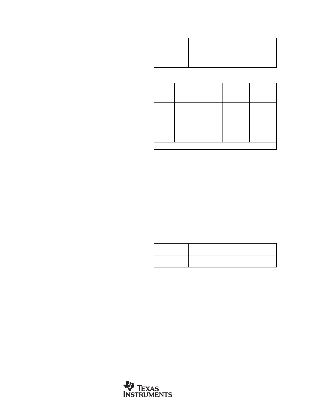
output data format, as shown in Table I. Table II shows the
jumper configuration for JP001 for normal operation.
SW001 SW002 SW003 RECEIVER OUTPUT DATA FORMAT
L L L 16- to 24-Bit Left-Justified
L H L 16- to 24-Bit I
H L H 16-Bit Right-Justified (or Standard)
L H H 18-Bit Right-Justified (or Standard)
2
S
TABLE I. Digital Audio Receiver Configuration.
16-BIT 18-BIT 16- TO 24-BIT
JP001 JUSTIFIED JUSTIFIED I
RIGHT RIGHT 16- TO 24-BIT LEFT
JUMPER FORMAT FORMAT FORMAT FORMAT
CLKO X X X X
SCLK O O O O
GND O O O O
BCK O O O NC
BCK (L.Just.) NC NC NC O
LRCK O O O O
DATA O O O O
NOTE: O = Install Jumper; NC = Remove Jumper; X = Don’t Care,
2
S JUSTIFIED
TABLE II. JP001 Jumper Configuration.
Switch SW004 is a normally open, momentary-contact pushbutton switch used to reset the digital audio receiver when
necessary.
The demonstration board also supports direct interfacing to
audio decoders and signal processors via connector CN004
(unpopulated). SCLK, BCK, LRCK, and DATA are available and buffered by U005. In addition, +5V (VCC) and
Ground are available at CN004. Switch SW005 is used to
select between the digital audio receiver and connector
CN004 as the source of the audio interface. Table III shows
the available switch settings.
SW005
SETTING SOURCE SELECTION
INT Digital Audio Receiver (U002)
EXT Connector CN004 via Buffer U005
TABLE III. Digital Audio Source Selection.
DIP-SWITCH CONFIGURATION
Switch SW006 is not utilized for the PCM1742. It is included for future products that may be compatible with this
demonstration board. All switch elements must be set to the
OFF position for the PCM1742.
PC PARALLEL PORT/HOST CONNECTOR
The evaluation fixture includes a Centronics connector, CN003,
thatis used to connect to a PC parallel port or an alternative
host controller. This connector is utilized to access the serial
control port of the PCM1742. The serial control port is used to
program the PCM1742’s internal registers. A standard printer
cable is used to connect CN003 of the evaluation fixture to a
PC parallel port. The port signals are buffered using U006.
2
DEM-DAI1742
SBAU034
Page 3
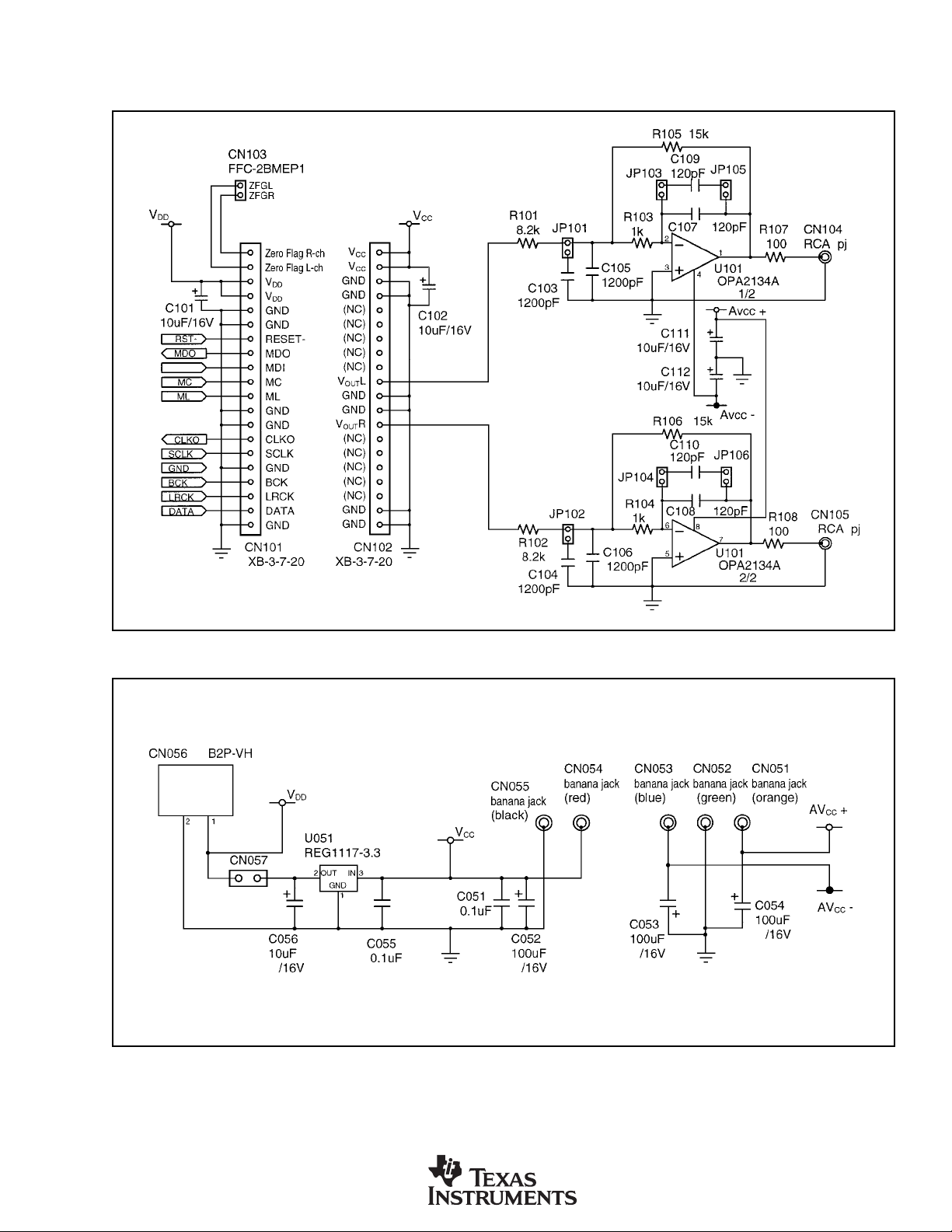
SCHEMATICS
Figures 1 through 4 provide schematics for the DEM-DAI1742.
FIGURE 1. DAC Low-Pass Filters.
FIGURE 2. Power-Supply Connections.
DEM-DAI1742
SBAU034
3
Page 4

FIGURE 3. DAC, Digital Audio Interface, and I/O Connections.
4
DEM-DAI1742
SBAU034
Page 5
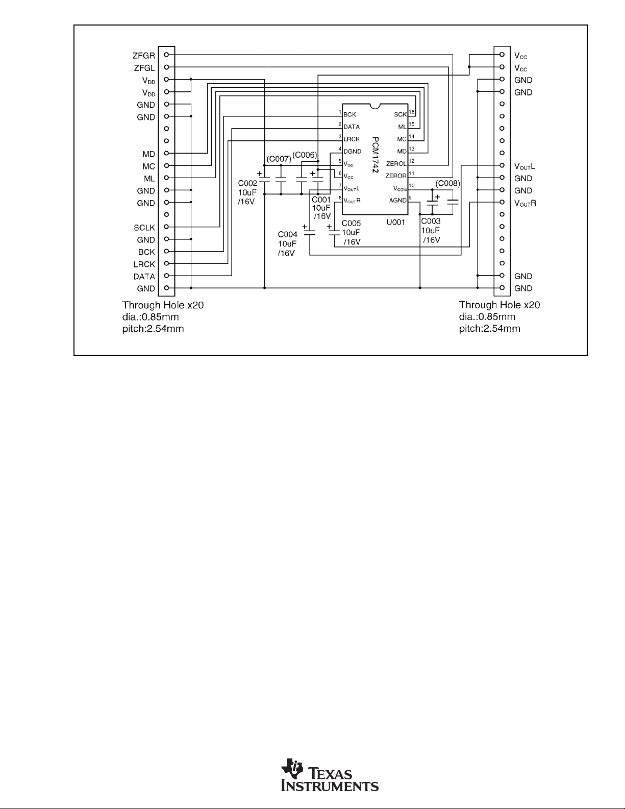
FIGURE 4. PCM1742 Daughter Card Schematic.
DEM-DAI1742
SBAU034
5
Page 6

PCB LAYOUT
Figures 5 through 10 provide PCB plots for the DEM-DAI1742.
FIGURE 5. DEM-DAI/DAC Silk Screen (Top Side).
6
DEM-DAI1742
SBAU034
Page 7

FIGURE 6. DEM-DAI/DAC Top-Side Layer.
FIGURE 7. DEM-DAI/DAC Bottom-Side Layer.
DEM-DAI1742
SBAU034
7
Page 8

FIGURE 8. PCM1742 Daughter Card Silk Screen (Top Side).
FIGURE 9. PCM1742 Daughter Card Top-Side Layer. FIGURE 10. PCM1742 Daughter Card Bottom-Side Layer.
8
DEM-DAI1742
SBAU034
Page 9

DEMONSTRATION SOFTWARE
FOR THE PCM1742
Software is provided with the DEM-DAI1742 to allow
programming of the PCM1742’s internal registers. The
software will operate on computers running Microsoft Windows 3.1/95/98. The demo software requires that the PC
printer port be connected to CN003 of the DEM-DAI1742
using a standard printer cable.
INSTALLATION
The demo software is distributed on a 3.5-inch floppy disk.
There is a single folder on the disk, named “Dem1742”. This
folder contains the application and all support files.
To install the software on your computer, first create a new
folder on your hard drive with an appropriate name (e.g.
Dem1742, Pcm1742, etc). Then open the “Dem1742” folder
on the installation floppy and copy all of the files in it to the
new folder that you created on your hard disk.
Open the configuration settings file named “Dem1742” with
a text editor, such as Notepad or WordPad. When the file is
opened, find the following line:
PCMIFADR = &h378
The &h378 indicates the printer port address that the demo
software will use to communicate with the DEM-DAI1742.
This address must be set to &h378, &h278, or &h3BC. Most
PCs use &H378 as the default printer port address. If your
printer port is not located at &h378, edit the address to match
your computer’s port address.
USING THE DEMO SOFTWARE
Double click on the application file named “Dem1742”. A
window will appear on your screen, as shown in Figure 11.
There are two menus near the top of the window, named
Execute and Window.
The Execute menu includes three selections: Initialize, Reset, and Exit. Selecting Initialize will instruct the program to
write all of the PCM1742’s internal registers with the default
values. Selecting Reset will instruct the program to rewrite
the PCM1742’s internal registers with the data currently
selected in the application windows. Selecting Exit will
close the application.
The Window menu includes three selections: Attenuation,
Operational Control, and Function Control. The following
sections provide an explanation of each window.
HOLD and PASS
Each window has a button near the top. It’s labeled either
HOLD or PASS. The setting is toggled by clicking on this
button. When set to HOLD, the user can change the settings
in a window but they will not be written to the register(s)
until the OK button (which appears at the bottom left corner
of the window) is pressed. When set to PASS, changes made
within a window are immediately written to the corresponding register(s).
The Attenuation Window
The Attenuation window is used to set the digital attenuation
registers internal to the PCM1742 and is shown in Figure 12.
There is an attenuator for both the left and right output
channels, and each attenuator has its own independent reg-
FIGURE 11. Startup Window.
DEM-DAI1742
SBAU034
FIGURE 12. Attenuation Window.
9
Page 10

ister to control its level. In the Attenuation window, there is
a slider for each attenuator register. Use the slider handle or
the arrows at each end of the slider to adjust the attenuation
level. The left and right arrow keys on the keyboard can also
be used to adjust the level. Just below each slider is a status
display showing the current register setting (in decimals)
and the corresponding attenuation level in decibels (dB).
The Operational Control Window
The Operational Control window is shown in Figure 13.
This window is used to set the following functions:
• Soft Mute (Mute Lch, Mute Rch): ON or OFF
• DAC operation (DAC Lch, DAC Rch): ON or OFF
•
Digital De-Emphasis (DEM): OFF, 32kHz, 44.1kHz, or 48kHz
The Function Control Window
The Function Control window is shown in Figure 14. This
window is used to set the following functions:
• Audio Data Format (Format)
• Digital Filter Low-Pass Response (Roll-Off): Sharp or Slow
• Zero Flag Output: Active HIGH or Active LOW
• Output Phase: Normal or Inverted
• L/R Zero Flag: Independent or Common
• Oversampling Rate: 64/32fS or 128/64f
S
FIGURE 13. Operational Control Window.
For more information regarding these functions, refer to the
PCM1742 data sheet.
FIGURE 14. Function Control Window.
For more information regarding these functions, refer to the
PCM1742 data sheet.
10
DEM-DAI1742
SBAU034
 Loading...