

Texas Instruments BQ2168MODULE, BQ2168LMODULE, BQ2168LB-KT, BQ2168B-KT, BQ2168B-005 Datasheet
Features
➤
Complete and compact lithium ion gas gauge and
protection solution for three or four series cells
➤
Accurate measurement of available battery
capacity
➤
Provides overvoltage, undervoltage, and
overcurrent protection
➤
Designed for battery pack integration
–
Small size
–
Includes bq2050H and bq2058 ICs
–
On-board charge and discharge control FETs
–
Low operating current for minimal battery drain
➤ High side FET control
➤ Battery capacity available through single-wire
serial port
➤ “L” version includes 5 push-button activated LEDs
to display state-of-charge information
General Description
The bq2168 Power Gauge Module provides a complete and
compact battery management solution for Li-Ion battery
packs. Designed for battery pack integration, the bq2168
combines the bq2050H Power Gauge IC with the bq2058
Supervisor IC on a small printed circuit board. The board
includes all the necessary components to accurately monitor
battery capacity and protect the cells from overvoltage, un
dervoltage, and overcurrent conditions. The board works
with three or four Li-Ion series cells.
The Power Gauge IC uses the on-board sense resistor to
track charge and discharge activity of the battery pack.
Critical battery information can be accessed through the
serial communications port at HDQ. The supervisor cir
cuit consists of the bq2058 and two FETs. The bq2058
controls the FETs to protect the batteries during
charge/discharge cycles and short circuit conditions. The
bq2168 provides contacts for the positive and negative
terminals of each battery in the stack. Please refer to
the bq2050H and bq2058 data sheets for the specifics on
the operation of the power gauge and supervisor ICs.
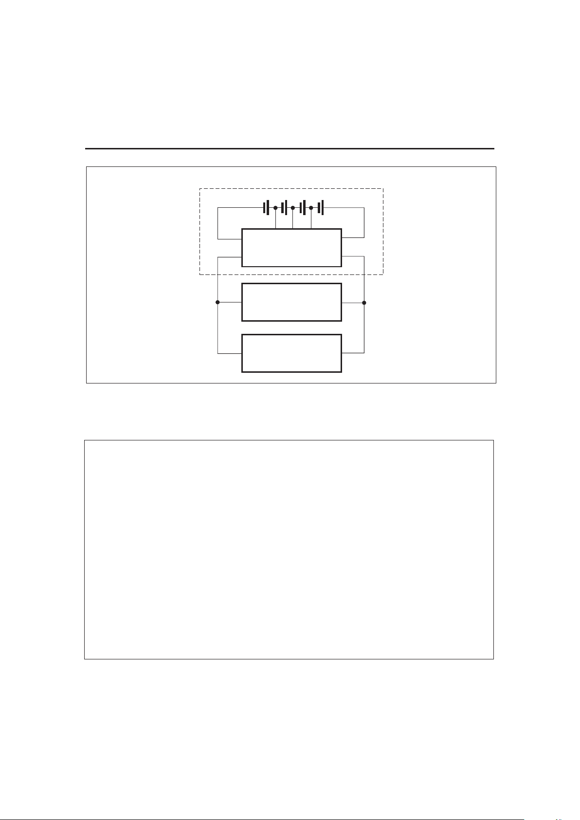
Unitrode configures the bq2168 based on the informa
tion requested in Table 1. The configuration defines the
number of series cells, the nominal battery pack capac
ity, the self-discharge rate, the Li-Ion battery type (coke
or graphite anode), and the threshold limits. Figure 1
shows how the module connects to the cells.
The bq2168L includes five LEDs to display remaining capacity in 20% increments of the learned capacity. The LEDs are
activated with the onboard push-button switch.
A module development kit is also available for the
bq2168. The bq2168B-KT or the bq2168LB-KT includes
one configured module and the following:
1) An EV2200-50H interface board that allows connection to the serial port of any AT-compatible com
-
puter.
2) Menu driven software to display charge/discharge
activity and to allow user interface to the bq2050H
from any standard Windows 3.1x or 95 PC.
Pin Descriptions
POS
Pack positive
B1P
BAT
1P
/Battery 1 positive input
B1N
BAT
1N
/Battery 1 negative input
B2N
BAT
2N
/Battery 2 negative input
B3N
BAT
3N
/Battery 3 negative input
B4N
BAT
4N
/Battery 4 negative input
ITEST
Overcurrent test input
HDQ
Serial communications port
NEG
Pack negative
1
bq2168
5/99 B
Li-Ion Power Gauge™ Module
with Pack Supervisor
2
bq2168
FG2168-1.eps
Battery Pack
B4N
B3N B2N B1N
B1P
NEG POS
bq2168
Load
Charger
Cells
PACK+PACK-
Figure 1. Module Connection Diagram
Customer Name: ___________________________________________________________________________
Contact: _________________________________________ Phone: ______________________________
Address: _________________________________________________________________________________
_________________________________________________________________________________
Sales Contact: ____________________________________ Phone: ______________________________
Number of series cells (3 or 4) _____________
Coke or graphite cell anode _____________
Battery pack capacity (mAh) _____________
Discharge current into load (3.9A max.) min. ________ avg. _________ max. _________
Charge current (3.9A max) _____________
Self-discharge compensation (Y/N) _____________
Overvoltage threshold (4.25, 4.30, or 4.35V) _____________
LEDs and switch (Y/N) _____________
FAE approval: ____________________________________ Date: _______________________________
Table 1. bq2168 Module Configuration
3
bq2168
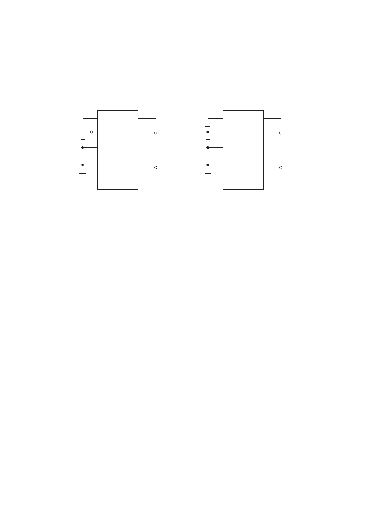
FG2158cc.eps
B1P
NC
Load
or
Charger
Three-Cell Configuration
POS
NEG
B1N
B2N
B3N
B4N
B1P
Load
or
Charger
Four-Cell Configuration
POS
NEG
B1N
B2N
B3N
B4N
Note: B1P, B4N, POS, and NEG accomodate a #20 AWG stranded wire.
B1N, B2N, and B3N accomodate a #24 AWG stranded wire.
Figure 1. Module Connection Diagram

4
Component values depend on user-provided information in Table 1.
2168La.eps
1 2 3 4
bq2168 Schematic
bq2168

5
2168Lb
bq2168 Schematic (Continued)
bq2168

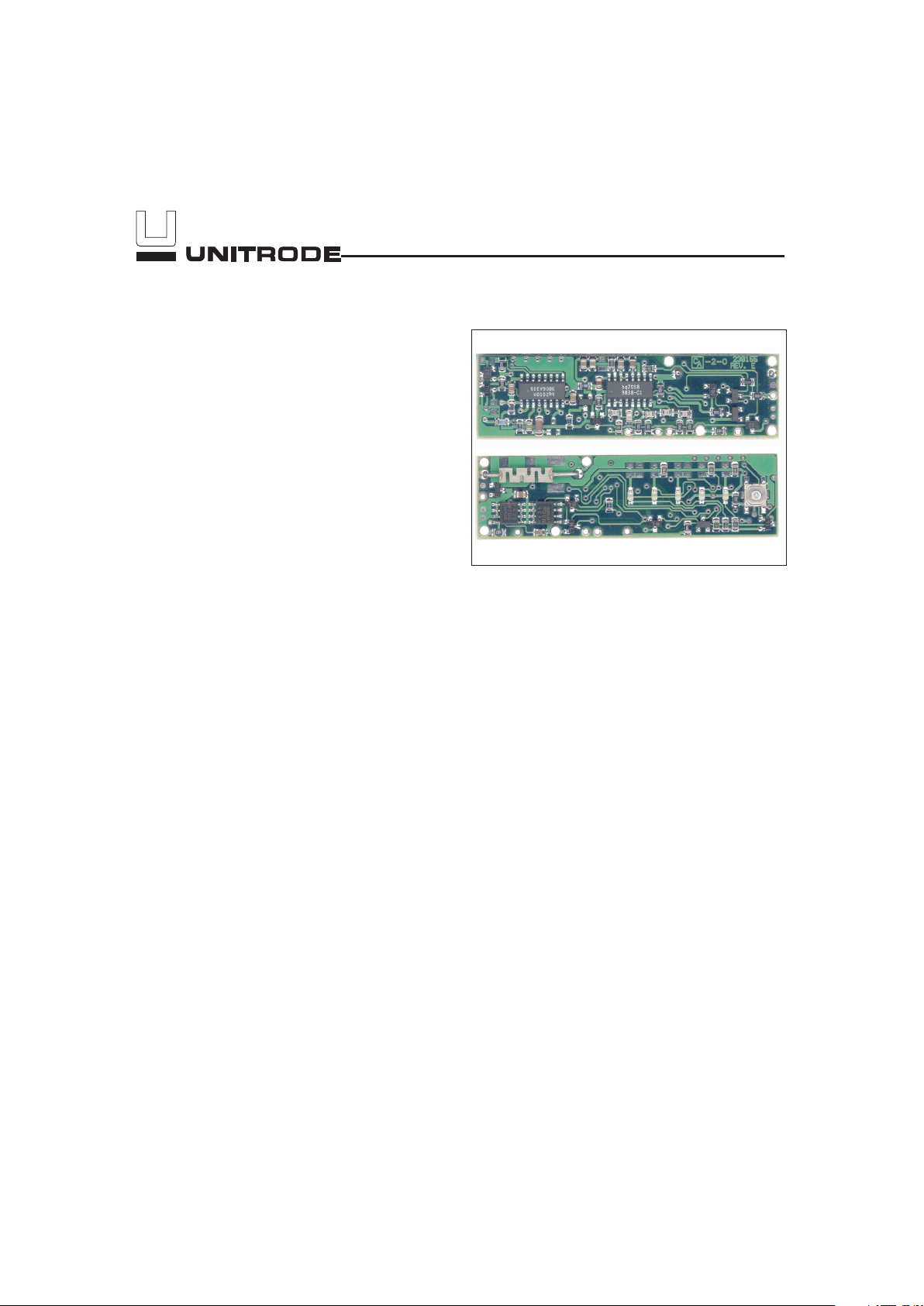
6
bq2168
bq2168 Board

7
Absolute Maximum Ratings
Symbol Parameter Value Unit Conditions
V
OP
Supply voltage (B1P to B4N) 18 V DC
V
TR
Maximum transient voltage (B1P to B4N) 32 V
Maximum duration =
1.5µs
V
CHG
Charging voltage (POS to NEG) 18 V
I
CHG
Continuous charge/discharge current 3.9 A
V
OP
> 6V
T
A
= 25°C
T
OPR
Operating temperature 0 to +70 °C
T
STG
Storage temperature -55 to +125 °C
Note: Permanent device damage may occur if Absolute Maximum Ratings are exceeded. Functional operation
should be limited to the Recommended DC Operating Conditions detailed in this data sheet. Exposure to con
-
ditions beyond the operational limits for extended periods of time may affect device reliability.
DC Electrical Characteristics (T
A=TOPR
)
Symbol Parameter Minimum Typical Maximum Unit Conditions/Notes
V
OP
Operating voltage, B1P to
B4N
4.0 - 18 V
I
CCA
Operating current - - 350
µ
A
R
ON
On resistance, B1P to POS - - 50
m
Ω
T
A
= 25°C
V
OP
= 10V
bq2168

8
DC Thresholds (T
A=TOPR
)
Symbol Parameter Value Tolerance Unit Notes
V
OV
Overvoltage threshold 4.25
±
50mV V
V
CE
Charge enable voltage VOV- 100mV
±
50mV V
V
UV
Undervoltage limit 2.25
±
100mV V
I
OC
Overcurrent limit
3.4 A
T
A
= 25°C
3.8 A
T
A
= 60°C
t
UVD
Undervoltage delay 950
±50%
ms
T
A
= 30°C
V
CD
Charge detect threshold 70 -60, +80 mV
t
OVD
Overvoltage delay 950
±50%
ms
T
A
= 30°C
t
OCD
Overcurrent delay 12
±60%
ms
T
A
= 30°C
Note: The thresholds above reflect the operation of a bq2158 using the standard bq2058 IC (VOV= 4.25V).
Specify other versions of the bq2058 by indicating the appropriate V
OV
threshold in Table 1.
bq2168
LED Option:
L = LEDs plus switch
Blank = No LEDs or switch
Notes: 1. Requires configuration sheet (Table 1)
2. Example production part number: bq2168LB-001
Ordering Information
bq2168 B —
Customer Code:
Blank = Sample or Pre-production
1
KT = Evaluation system
XXX = Customer-specific; assigned by Unitrode
2
Package Option:
B = Board-level product
Device:
Li-Ion Power Gauge Module with Pack Supervisor
Change No. Page No. Description Nature of Change
1 All From Preliminary to Final
Note: Change 1 = May 1999 B changes from Apr. 1999.
Data Sheet Revision History

IMPORTANT NOTICE
T exas Instruments and its subsidiaries (TI) reserve the right to make changes to their products or to discontinue
any product or service without notice, and advise customers to obtain the latest version of relevant information
to verify, before placing orders, that information being relied on is current and complete. All products are sold
subject to the terms and conditions of sale supplied at the time of order acknowledgement, including those
pertaining to warranty, patent infringement, and limitation of liability.
TI warrants performance of its semiconductor products to the specifications applicable at the time of sale in
accordance with TI’s standard warranty. Testing and other quality control techniques are utilized to the extent
TI deems necessary to support this warranty. Specific testing of all parameters of each device is not necessarily
performed, except those mandated by government requirements.
CERT AIN APPLICATIONS USING SEMICONDUCT OR PRODUCTS MAY INVOLVE POTENTIAL RISKS OF
DEATH, PERSONAL INJURY, OR SEVERE PROPERTY OR ENVIRONMENTAL DAMAGE (“CRITICAL
APPLICATIONS”). TI SEMICONDUCTOR PRODUCTS ARE NOT DESIGNED, AUTHORIZED, OR
WARRANTED TO BE SUITABLE FOR USE IN LIFE-SUPPORT DEVICES OR SYSTEMS OR OTHER
CRITICAL APPLICATIONS. INCLUSION OF TI PRODUCTS IN SUCH APPLICA TIONS IS UNDERSTOOD T O
BE FULLY AT THE CUSTOMER’S RISK.
In order to minimize risks associated with the customer’s applications, adequate design and operating
safeguards must be provided by the customer to minimize inherent or procedural hazards.
TI assumes no liability for applications assistance or customer product design. TI does not warrant or represent
that any license, either express or implied, is granted under any patent right, copyright, mask work right, or other
intellectual property right of TI covering or relating to any combination, machine, or process in which such
semiconductor products or services might be or are used. TI’s publication of information regarding any third
party’s products or services does not constitute TI’s approval, warranty or endorsement thereof.
Copyright 1999, Texas Instruments Incorporated
 Loading...