

Page 1

AM572x Industrial Development Kit (IDK)
Evaluation Module (EVM) Hardware
User's Guide
Literature Number: SPRUI64C
May 2017–Revised April 2018
Page 2

Contents
Preface ........................................................................................................................................ 5
1 Introduction......................................................................................................................... 6
1.1 Description ................................................................................................................ 6
1.2 System View .............................................................................................................. 7
2 Functional Description........................................................................................................ 11
2.1 Processor................................................................................................................ 12
2.2 Clocks.................................................................................................................... 12
2.3 Reset Signals ........................................................................................................... 12
3 Power Supplies .................................................................................................................. 13
3.1 Power Source ........................................................................................................... 13
3.2 TPS6590377 PMIC..................................................................................................... 13
3.3 AVS Control ............................................................................................................. 13
3.4 Other Power Supplies.................................................................................................. 13
4 Configuration/Setup............................................................................................................ 15
4.1 Boot Configuration...................................................................................................... 15
4.2 I2C Address Assignments ............................................................................................. 15
4.3 SEEPROM Header ..................................................................................................... 16
4.4 JTAG Emulation ........................................................................................................ 16
5 Memories Supported........................................................................................................... 17
5.1 DDR3L SDRAM......................................................................................................... 17
5.2 SPI NOR Flash.......................................................................................................... 17
5.3 Board Identity Memory................................................................................................. 17
5.4 SD/MMC ................................................................................................................. 17
5.5 eMMC NAND Flash .................................................................................................... 17
6 Ethernet Ports.................................................................................................................... 18
6.1 100Mb Ethernet Ports on PRU-ICSS ................................................................................ 18
6.2 Gigabit (1000Mb) Ethernet Ports..................................................................................... 18
7 USB Ports.......................................................................................................................... 19
7.1 Processor USB Port 1.................................................................................................. 19
7.2 Processor USB Port 2.................................................................................................. 19
7.3 FTDI USB Port .......................................................................................................... 19
8 PCIe.................................................................................................................................. 19
9 Video Input and Output....................................................................................................... 20
9.1 Camera................................................................................................................... 20
9.2 HDMI ..................................................................................................................... 20
9.3 LCD....................................................................................................................... 20
10 Industrial Interfaces............................................................................................................ 20
10.1 Profibus .................................................................................................................. 20
10.2 DCAN..................................................................................................................... 20
10.3 RS-485................................................................................................................... 20
11 User Interfaces................................................................................................................... 21
2
Table of Contents
Copyright © 2017–2018, Texas Instruments Incorporated
SPRUI64C–May 2017–Revised April 2018
Submit Documentation Feedback
Page 3

www.ti.com
11.1 Tri-color LEDs........................................................................................................... 21
11.2 Industrial Inputs ......................................................................................................... 21
11.3 Industrial Outputs / LEDs.............................................................................................. 21
12 Pin Use Description............................................................................................................ 21
12.1 Functional Interface Mapping ......................................................................................... 21
12.2 GPIO Pin Mapping...................................................................................................... 21
13 Board Connectors .............................................................................................................. 23
14 EVM Important Notice ......................................................................................................... 36
Appendix A Known Deficiencies in AM572x IDK EVM ..................................................................... 37
A.1 Power solution not sufficient for full PCIe plug-in card compliance............................................. 37
A.2 Early versions of the AM572x IDK EVM not installed with SOC devices rated for the full industrial
temperature range...................................................................................................... 37
A.3 AM572x IDK EVM does not support eMMC HS200 mode....................................................... 37
A.4 PCIe PERSTn line not in proper state at start-up................................................................. 37
A.5 EDIO connectors J4 and J7 should support real-time debugging for both PRU1 and PRU2............... 37
A.6 HDQ implementation not correct.................................................................................... 37
A.7 Removing the power plug and inserting it again while the power supply is energized may cause
damage .................................................................................................................. 37
A.8 Software shutdown of PMIC not operational ...................................................................... 38
A.9 PMIC implementation does not support required SOC shut-down sequence................................. 38
A.10 USB port providing UART console and XDS100 emulation not isolated from EVM board supplies ....... 38
A.11 Need 47-µf capacitor at camera header............................................................................ 38
A.12 Decoupling capacitors do not reflect AM572x PDN recommendations ........................................ 38
A.13 CCS System Reset fails ............................................................................................. 38
A.14 AM572x IDK EVM design contains 2 clamp circuits that may not be necessary ............................. 39
A.15 Crystal connected to osc0 needs to have 50 ppm or better long term accuracy ............................. 39
A.16 Software must program the CDCE913 for 0-pf load capacitance............................................... 39
A.17 Protection diode D2 should be rated for 5 V....................................................................... 39
A.18 PHY address LSB for U9 and U15 can be latched incorrectly .................................................. 39
A.19 3.3-V clamp circuit needs more margin ............................................................................ 39
A.20 Current PMIC does not provide the mandated power down sequence ........................................ 40
A.21 PMIC OSC16MCAP pin mistakenly grounded .................................................................... 40
Revision History.......................................................................................................................... 41
SPRUI64C–May 2017–Revised April 2018
Submit Documentation Feedback
Copyright © 2017–2018, Texas Instruments Incorporated
Contents
3
Page 4

www.ti.com
List of Figures
1 AM572x IDK EVM - Top View.............................................................................................. 7
2 AM572x IDK EVM - Bottom View.......................................................................................... 8
3 AM572x IDK EVM with LCD Display Assembly Attached - Top View ................................................ 9
4 AM572x IDK EVM with LCD Display Assembly Attached - Bottom View........................................... 10
5 AM572x IDK EVM Block Diagram ....................................................................................... 11
6 Connections from the TPS6590377 PMIC to the AM572x Processor............................................... 14
List of Tables
1 I2C1/IND_I2C ............................................................................................................... 15
2 I2C2/AM572X_HDMI_DDC ............................................................................................... 15
3 SEEPROM Header......................................................................................................... 16
4 PRU-ICSS Ethernet Ports................................................................................................. 18
5 GPIO Pin Mapping ......................................................................................................... 22
6 Expansion Connector - J21 ............................................................................................... 23
7 I/O Expansion Header Connector - J37................................................................................. 25
8 MicroSD Connector - J15 ................................................................................................. 26
9 Power Jack Connector - J1 ............................................................................................... 26
10 Power Terminal Block Connector - J2................................................................................... 26
11 PRU1ETH0 RJ45 Connector - J3........................................................................................ 27
12 PRU1ETH1 RJ45 Connector - J5........................................................................................ 27
13 PRU2ETH0 RJ45 Connector - J6........................................................................................ 28
14 PRU2ETH1 RJ45 Connector - J8........................................................................................ 28
15 PRU2ETH0 Test Header Connector - J7 ............................................................................... 29
16 PRU2ETH1 Test Header Connector - J4 ............................................................................... 29
17 Camera Connector - J9.................................................................................................... 29
18 GigE RJ45 Connector - J10............................................................................................... 30
19 GigE RJ45 Connector - J12............................................................................................... 30
20 LCD Module FFC Connector - J16....................................................................................... 31
21 Touchscreen Controller FFC Connector - J17 ......................................................................... 31
22 HDMI Standard A-type Connector - J24 ................................................................................ 32
23 MIPI-60 JTAG Connector - J18 .......................................................................................... 32
24 JTAG USB Micro-AB Connector - J19 .................................................................................. 34
25 USB Port 1 USB3.0 Standard A-type Connector - J23................................................................ 34
26 USB Port 2 USB2.1 Micro-AB Connector - J45 ........................................................................ 34
27 CAN Header Connector - J38 ............................................................................................ 35
28 Profibus DB9F Connector - J14.......................................................................................... 35
29 RS-485 Header Connector - J39......................................................................................... 35
30 PCIe Connector – J22..................................................................................................... 36
4
List of Figures
Copyright © 2017–2018, Texas Instruments Incorporated
SPRUI64C–May 2017–Revised April 2018
Submit Documentation Feedback
Page 5

About This Manual
This document describes the hardware architecture of the AM572x Industrial Development Kit (IDK)
Evaluation Module (EVM) (Part# TMDXIDK572x) that supports the Texas Instruments Sitara™ ARM
Cortex®-A15 AM572x processor family.
Glossary
TI Glossary —This glossary lists and explains terms, acronyms, and definitions.
Related Documentation From Texas Instruments
For product information, visit the Texas Instruments website at http://www.ti.com.
SPRABY8— AM572x GP EVM Power Simulations Application Report
SPRS953— AM572x Sitara Processors Silicon Revision 2.0 Data Manual
SPRZ429— AM572x Sitara Processors Silicon Errata. Describes the known exceptions to the functional
specifications for the device.
Preface
SPRUI64C–May 2017–Revised April 2018
Read This First
®
SPRUHZ6— AM572x Sitara Processors Technical Reference Manual. Details the integration, the
environment, the functional description, and the programming models for each peripheral and
subsystem in the device.
Community Resources
The following links connect to TI community resources. Linked contents are provided "AS IS" by the
respective contributors. They do not constitute TI specifications and do not necessarily reflect TI's views;
see TI's Terms of Use.
TI E2E™ Online Community— TI's Engineer-to-Engineer (E2E) Community. Created to foster
collaboration among engineers. At e2e.ti.com, you can ask questions, share knowledge, explore
ideas and help solve problems with fellow engineers.
TI Embedded Processors Wiki— Texas Instruments Embedded Processors Wiki. Established to help
developers get started with Embedded Processors from Texas Instruments and to foster innovation
and growth of general knowledge about the hardware and software surrounding these devices.
Trademarks
Sitara, E2E, Code Composer Studio, SmartReflex are trademarks of Texas Instruments.
ARM, Cortex are registered trademarks of ARM Limited.
Windows is a registered trademark of Microsoft Corporation.
SPRUI64C–May 2017–Revised April 2018
Submit Documentation Feedback
Copyright © 2017–2018, Texas Instruments Incorporated
Preface
5
Page 6

1 Introduction
This document describes the hardware architecture of the AM572x Industrial Development Kit (IDK)
Evaluation Module (EVM) (Part# TMDXIDK572x) that supports the Texas Instruments Sitara™ ARM
Cortex®-A15 AM572x processor family.
1.1 Description
The AM572x IDK is a standalone test, development, and evaluation module that enables developers to
write software and develop hardware for industrial control and industrial communications applications. It
has been equipped with a TI AM5728 processor and a defined set of features to allow you to experience
industrial communication solutions using various serial or Ethernet based interfaces. Using standard
interfaces, the AM572x IDK may interface to other processors or systems and act as a communication
gateway or controller. In addition, it can directly operate as a standard remote I/O system or a sensor
connected to an industrial communication network.
The AM572x IDK contains embedded emulation circuitry to quickly enable developers to begin using this
IDK. The embedded emulation logic allows emulation and debug using standard development tools such
as the Texas Instruments Code Composer Studio™ integrated development environment (IDE) by simply
connecting a USB cable to a Windows®-based computer.
The standard configuration for the AM572x IDK EVM provides the following Ethernet connectivity:
• Two Gigabit (1000Mb) metallic ports connected via PHY/RGMII to the on-chip Ethernet switch
• Two 100Mb metallic ports connected via PHY/MII to the PRU-ICSS subsystems
Reconfiguration through resistor removal and installation can provide an alternate Ethernet connectivity:
• Four 100Mb metallic ports connected via PHY/MII to the PRU-ICSS subsystems
Software support for the AM572x IDK EVM is provided within the Processor Software Development Kit
(SDK) package. This includes both Linux and RTOS support.
User's Guide
SPRUI64C–May 2017–Revised April 2018
AM572x Industrial Development Kit (IDK)
Evaluation Module (EVM) Hardware
®
6
AM572x Industrial Development Kit (IDK) Evaluation Module (EVM)
Hardware
Copyright © 2017–2018, Texas Instruments Incorporated
SPRUI64C–May 2017–Revised April 2018
Submit Documentation Feedback
Page 7

www.ti.com
1.2 System View
The system view of the AM572x IDK EVM consists of the main board and the camera board. There is also
an optional LCD panel and touch screen assembly that can be attached to the AM572x IDK EVM.
The top and the bottom views of the AM572x IDK EVM are provided in Figure 1 and Figure 2,
respectively.
The top and the bottom views of the AM572x IDK EVM with the optional LCD display assembly attached
are provided in Figure 3 and Figure 4, respectively.
Introduction
Figure 1. AM572x IDK EVM - Top View
SPRUI64C–May 2017–Revised April 2018
Submit Documentation Feedback
AM572x Industrial Development Kit (IDK) Evaluation Module (EVM)
Copyright © 2017–2018, Texas Instruments Incorporated
Hardware
7
Page 8

Introduction
www.ti.com
Figure 2. AM572x IDK EVM - Bottom View
8
AM572x Industrial Development Kit (IDK) Evaluation Module (EVM)
Hardware
Copyright © 2017–2018, Texas Instruments Incorporated
SPRUI64C–May 2017–Revised April 2018
Submit Documentation Feedback
Page 9

www.ti.com
Introduction
Figure 3. AM572x IDK EVM with LCD Display Assembly Attached - Top View
SPRUI64C–May 2017–Revised April 2018
Submit Documentation Feedback
AM572x Industrial Development Kit (IDK) Evaluation Module (EVM)
Copyright © 2017–2018, Texas Instruments Incorporated
Hardware
9
Page 10

Introduction
www.ti.com
Figure 4. AM572x IDK EVM with LCD Display Assembly Attached - Bottom View
10
AM572x Industrial Development Kit (IDK) Evaluation Module (EVM)
Hardware
Copyright © 2017–2018, Texas Instruments Incorporated
SPRUI64C–May 2017–Revised April 2018
Submit Documentation Feedback
Page 11

AM572x
DDR1
QSPI
RGMII0
MMC1
HDMI / I2C2
PCIe / I2C1
TLK105L
HDMI
PCIe x1
GbE
ICSS1
RJ45
MMC2
I2C
DDR3
1GB
QSPI
32MB
eMMC
16GB
uSD
EEPROM
USB2.0
MicroAB
PR2_MII0
I2C
USB2
UART
Camera
Header
VIN4B / I2C1
JTAG
JTAG
(60-pin)
ICs
TI ICs
Connectors
ISO1176T
Profibus
DB9
PRU UART
TLK105L
TPS6590377
PMIC
ICSS1
RJ45
TLK105L
ICSS0
RJ45
TLK105L
ICSS0
RJ45
KSZ9031
DDR3
1GB
w/ECC
PR2_MII1
PR1_MII1
(muxed
with
RGMII1)
ICSS Header
prx_mii0/1_txen/rxdv,
prx_edio_data_out + sync
Warm
RESET
INT
RGY LED ENET Status
GPIO
GPIO
RGMII1
GbE
KSZ9031
DCAN1
DDR2
USB1
USB3.0
Std A
FTDI
USB
SN65HVD78D
RS485
Header
UART2
Industrial Inputs &
Outputs/LEDs
SPI3 / I2C1
LCD &
Touch Panel
MIPI
Serializer
VOUT1/I2C1
ISO1050
TPD6E001
TPD4S012
TPD2EUSB30 &
TPD4E05U06
DCAN
Header
PR1_MII0
(muxed
with
RGMII0)
TPD12S016
www.ti.com
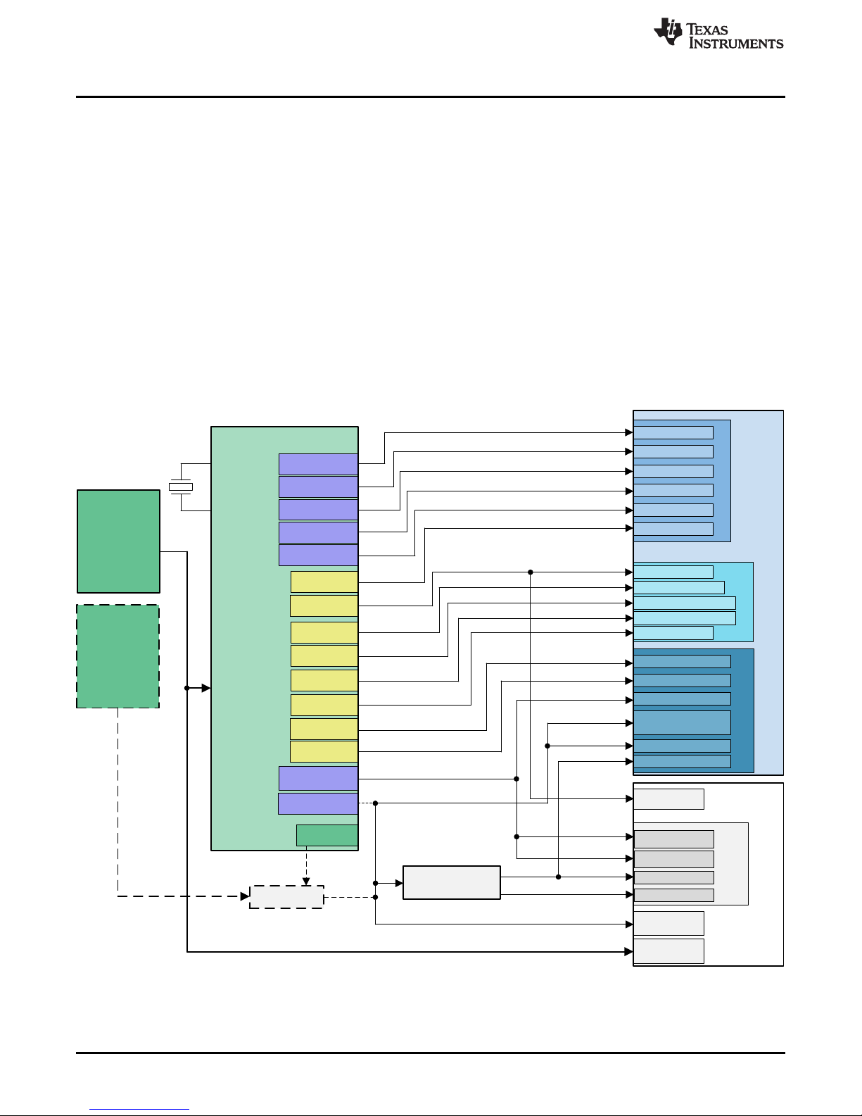
2 Functional Description
The AM572x IDK EVM is implemented on a single board with interface circuitry, memory ICs, and
connectors around the AM5728 processor. The board also contains power conversion circuitry to
efficiently create the needed power supply voltages from a single +5V input. As stated previously, this
EVM ships with a separate camera module that plugs in to the main board. An optional LCD panel and
touch screen assembly can be purchased separately and mounted on to the main board.
Figure 5 shows the functional block diagram of the AM572x IDK EVM.
Functional Description
Figure 5. AM572x IDK EVM Block Diagram
SPRUI64C–May 2017–Revised April 2018
Submit Documentation Feedback
Copyright © 2017–2018, Texas Instruments Incorporated
AM572x Industrial Development Kit (IDK) Evaluation Module (EVM)
Hardware
11
Page 12

Functional Description
2.1 Processor
The AM5728 processor is the central processing unit for this IDK EVM. The interface circuitry, memory
ICs, and connectors implemented on the board around the AM5728 processor provide development
support for the many industrial communication interfaces available on this platform. See the AM572x
Sitara Processors Silicon Revision 2.0 Data Manual (SPRS982) and the AM572x Sitara Processors
Technical Reference Manual (SPRUHZ6) for details about the processor.
The AM572x IDK EVM contains system configuration for the boot mode control inputs SYSBOOT[15..0].
These can be strapped using resistors. The default configuration will meet the needs of most developers.
Resistor reconfiguration is supported so that you can explore other boot configurations of the AM572x
processor. See Section 4 for more details.
2.2 Clocks
The main clock for the processor is derived from a 20-MHz crystal. An on-board oscillator in the AM572x
processor generates the base clock and the subsequent module clocks as needed within the AM572x
processor. The board design supports a crystal attached to the RTC block, but this is not needed since
RTC-only mode is not supported in this device.
2.3 Reset Signals
The AM572x processor contains 3 reset inputs and an output indicating a reset is in progress. The reset
pins are:
• PORz: PORz is a hard reset that resets everything including emulation logic. It also tri-states most
outputs.
• RESETn: RESETn is a device reset commonly driven by control logic or emulation.
• RTC_PORz: Separate PORz for the RTC module that must be driven at the same time as PORz.
(Note that PORz and RTC_PORz can only be directly connected as long as VDDSHV3 and VDDSHV5
are driven at the same voltage.)
• RSTOUTn: Output signal from SOC indicating that the device has entered reset. This is used to reset
other circuits that must be reset at the same time as the processor.
More details about the behavior of these reset pins within the AM572x processor can be found in the
AM572x Sitara Processors Silicon Revision 2.0 Data Manual (SPRS982). There are push buttons on the
IDK that can initiate either a RESETn or PORz input. SW1 can drive PORz active (low) and SW2 can
drive RESETn active (low).
There is a device erratum in all of the AM572x devices that prevents use of RESETn independent from
PORz. The workaround is to generate PORz whenever a device reset occurs even if it is from an internal
initiator. This is accomplished through cooperation with the PMIC paired with the AM572x device on the
IDK EVM. The RSTOUTn output from the AM572x device is connected to the NRESWARM input of the
PMIC. This initiates a re-start that drives RESET_OUT low and resets all voltages to their initial values.
Since RESET_OUT from the PMIC is connected to PORz in the AM572x device, a hard reset is forced on
the SOC that meets the needs of the erratum workaround.
The AM572x IDK EVM is started by pressing the start-up push button, SW3. The POWERHOLD input can
be connected to VRTC_OUT in customer designs to cause the board to power-on as soon as the main
supply is stable.
The configuration of the PMIC to provide RESET_OUT from the NRESWARM input creates an always-on
implementation. This always-on mode of operation prevents software shut-down of the IDK. Customer
designs should have power-good monitoring circuitry such as a TPS3808 connected to the main supply to
the PMIC that is connected to the PMIC RESET_IN. The TPS3808 can detect the main supply voltage
dropping and then trigger the PMIC to execute a controlled shut-down that meets the requirements in the
AM572x Sitara Processors Silicon Revision 2.0 Data Manual (SPRS982).
www.ti.com
12
AM572x Industrial Development Kit (IDK) Evaluation Module (EVM)
Hardware
Copyright © 2017–2018, Texas Instruments Incorporated
SPRUI64C–May 2017–Revised April 2018
Submit Documentation Feedback
Page 13

www.ti.com
3 Power Supplies
This section describes how the power supplies required for the design are generated.
3.1 Power Source
The AM572x IDK EVM uses an external 5V power supply. The 5V power input is converted into different
voltage levels to provide power inputs to the AM572x processor and other circuitry.
Early versions of the AM572x IDK EVM shipped with the GlobTek, Inc. external power supply with the part
number TR9CA6500LCP-N, model number GT-43008-3306-1.0-T3. This external power supply is rated for
an output voltage of +5VDC with an output current up to 6.5A. This external power supply contains
applicable regional product regulatory/safety certification requirements for most worldwide locations. If you
cannot use this supply, one with equivalent ratings that is approved for your location must be obtained.
The AM572x IDK EVM contains a right angle mounted power connector that accepts the +5VDC supply
input on the center pin with the outer shell as the common return. The power connector accepts a mating
plug with a 2.5mm ID and a 5.5mm OD.
Removing the power plug and inserting it again while the power supply is energized may damage the
AM572x IDK EVM and/or other devices attached to the board such as emulators that provide an alternate
path to ground. Removal of AC power from the external power supply is a safer method, if required.
It is recommended that the external power supply have the common return bonded to earth ground. If this
is not possible, a separate connection from the board ground to earth ground may need to be provided.
3.2 TPS6590377 PMIC
The power requirements of the processor are met by the TPS6590377 Power Management IC (PMIC).
The power sequencing requirements of the AM572x processor are also handled by the TPS6590377
PMIC. Figure 6 shows the supply connections from the TPS6590377 PMIC to the AM572x processor.
Refer to the AM572x Sitara Processors Silicon Revision 2.0 Data Manual (SPRS982) for more information
about the required supply voltages and supply sequencing. Also refer to the TPS659037 Power
Management Unit (PMU) for Processor Data Manual (SLIS165) and the TPS659037 User's Guide to
Power AM572x and AM571x User’s Guide (SLIU011) for details about its operation.
Note that the production version of the AM572x IDK EVM uses the TPS6590377 PMIC that supplies the
voltages needed for the latest silicon version of the AM5728 processor. Beta prototype IDK EVM units
used the TPS6590375 PMIC and Alpha prototype IDK EVM units used the TPS6590372 PMIC.
Power Supplies
3.3 AVS Control
The AM572x processor consumes most of its power in its core logic. Therefore, minimizing the voltage
supplied to this core logic can minimize power consumption. SmartReflex™ technology is used to provide
this optimized solution.
This core logic is separated into multiple segments that can each be controlled separately. In this way,
applications that need more performance in some processing blocks can operate at higher performance
levels by increasing the supply voltage, while other processing blocks that do not require the same level of
performance can operate at lower voltage thus further optimizing system power consumption.
The TPS6590377 PMIC is connected to the I2C1 on the AM5728 processor. This allows the application
software to individually control the AVS supply outputs. It also allows the application to control the voltage
generated by LDO1 that is used for the SDIO interface that operates at either 1.8V or 3.3V depending on
the operating mode.
3.4 Other Power Supplies
The AM572x IDK EVM contains 8 other power conversion devices that support the interface and memory
circuitry:
• TPS63010 Buck-Boost Converter: This converter generates 5.0V from the main supply input. It
supplies this voltage to the industrial interface circuits, the HDMI interface and to the USB master
ports.
SPRUI64C–May 2017–Revised April 2018
Submit Documentation Feedback
AM572x Industrial Development Kit (IDK) Evaluation Module (EVM)
Copyright © 2017–2018, Texas Instruments Incorporated
Hardware
13
Page 14
5-V Input
Power
SMPS1, SMPS2
AVS (6 A max)
SMPS4, SMPS5
AVS (4 A max)
SMPS6
AVS (3 A max)
SMPS8
AVS (1 A max)
SMPS7
AVS (2 A max)
LDO9
(50 mA max)
LDOLN
(100 mA max)
LDO3
(200 mA max)
LDOVRTC
(25 mA max)
LDO1
(300 mA max)
LDOUSB
(100 mA max)
SMPS3
(3 A max)
PMIC
TPS659037
TPS51200
5 V
VDD_MPU
VDD_DSPEVE
VDD_GPU
VDD_IVAHD
VDD_CORE
VDD_RTC
VDDSHV8 (SDIO)
VDDA_USB3V3
VDD_DDR
Dual-Voltage Rails
(set to 3.3 V)
1V8
3V3
5V0
EMIF1
EMIF2
VTT
DDR
Other Domains
Processor
Core Domains
1.06 V
1.15 V
1.15 V
1.05 V
1.06 V
1.06 V
1.35 V or 1.5 V
1.35 V or 1.5 V
1.8 V
1.8 V
1.35 V or 1.5 V
1.8 V
3.3 V
3.3 V
1.8 V
0.675 V or 0.75 V
1.8 V
Peripherals
DDR_REF
SMPS9
(1 A max)
LDO2
(300 mA max)
VDDSHV5 (RTC I/O)
3.3 V
3.3 V
VREF
0.675 V or 0.75 V
VDD_1V8
VDDA_1V8 (PLLs)
1V8_PHY (USB/SATA)
VDDA_RTC
1.8-V Domains
1V8_PHY (HDMI/PCIe)
LDO4
(200 mA max)
OSC16MIN
OSC16MOUT
1.8 V
3.3V Input
Power
TPS22965
(Power Switch)
REGEN1
Power Supplies
• TPS61085 Boost Converter: This converter generates 12.0V from the main supply input. It supplies
voltage to the industrial interface circuits and the PCIe card connector.
• TPS51200 DDR Termination Voltage LDO (2 each): This LDO provides the push/pull termination
current required for the DDR3 memory interfaces. There is one implemented for each DDR3 EMIF.
• LP38693ADJ Low-Dropout Regulator: This LDO generates the 3.7V LCD bias voltage.
• TPS61081DRC LCD Backlight Generator: This Boost converter generates the LCD backlight supply.
• TPS71712 Low-Dropout Regulator: This LDO generates the 1.2V supply needed for the LCD driver
logic.
• TPS76650 Low-Dropout Regulator: This LDO generates the 5.0V supply needed for the Profibus
interface.
• R1Z-3.305HP Isolated DC-DC Supply: This converter generates 5.0V isolated from the primary
3.3V DC supply on board for the DCAN interface.
www.ti.com
Figure 6. Connections from the TPS6590377 PMIC to the AM572x Processor
14
AM572x Industrial Development Kit (IDK) Evaluation Module (EVM)
Hardware
Copyright © 2017–2018, Texas Instruments Incorporated
SPRUI64C–May 2017–Revised April 2018
Submit Documentation Feedback
Page 15

www.ti.com
4 Configuration/Setup
This section discusses the board configuration.
4.1 Boot Configuration
Various boot configurations can be set using the pull-up/pull-down resistor combinations provided on the
SYSBOOT[15..0] pins. Boot configuration pins are latched upon de-assertion of the PORz pin. Refer to
the AM572x Sitara Processors Silicon Revision 2.0 Data Manual (SPRS982) for more details. The
AM572x IDK EVM is configured by default to 0x8106 to enable UBOOT/Linux boot from the SDCARD.
The secondary boot device selected by this boot mode is QSPI1.
4.2 I2C Address Assignments
The AM572x IDK EVM contains multiple I2C buses connected to a master port on the processor. Each
bus contains one or more I2C slave devices that must have unique addresses to prevent contention.
Table 1 and Table 2 list the addresses of the I2C slave devices attached to buses I2C1 and I2C2,
respectively.
I2C Slave Device Address(es)
TPS590377 PMIC, U3 0x58, 0x59, 0x5A, 0x5B, 0x12
Camera Header, J9 Undefined
CDCE913 Ethernet Clock Generator A, U23 0x65
TPIC2810 Industrial Output Driver, U89 0x60
LCD Panel Driver TC358778, U73 0x0E
Touchscreen FPC Connector, J17 —
ID Memory SEEPROM, U33 0x50
PCIe Card Connector, J22 Undefined
Expansion Connector, J21 Undefined
Configuration/Setup
Table 1. I2C1/IND_I2C
CDCE913 Ethernet Clock Generator B, U25 0x65
NOTE: SCL/SDA names are swapped between the HDMI DDC port and I2C2 port on AM57xx
devices – I2C2 schematic connections to U25 must be reversed.
SPRUI64C–May 2017–Revised April 2018
Submit Documentation Feedback
Table 2. I2C2/AM572X_HDMI_DDC
I2C Slave Device Address(es)
HDMI Bridge, U46 —
AM572x Industrial Development Kit (IDK) Evaluation Module (EVM)
Copyright © 2017–2018, Texas Instruments Incorporated
Hardware
15
Page 16

Configuration/Setup
4.3 SEEPROM Header
Each of the AM572x IDK EVMs has a unique serial number. This serial number is printed on a sticker
attached to the IDK and it is programmed into a SEEPROM memory device connected to the AM5728
processor over the I2C bus. The SEEPROM also contains board details such as board type, version,
configuration, and so on. This information is stored in a structure at the beginning of the SEEPROM in a
known format that can be read by the application software. These values are all stored with the first
character or MSB stored at the lowest addressable location in each field. Table 3 lists all of the fields in
this header definition.
Name Size (bytes) Contents
Header 4 MSB 0xEE3355AA LSB
Board Name 8 Name for board in ASCII “AM572” = AM572x Industrial Development Kit EVM.
Version 4 Hardware version code for board in ASCII “1.3A” = revision 01.3A
Serial Number 12
Configuration Option 32 Codes to show the configuration setup on this board. Reserved.
Ethernet MAC
Address #0
Ethernet MAC
Address #5
Available 32696 Available user space for other non-volatile codes/data.
www.ti.com
Table 3. SEEPROM Header
Serial number of the board. This is a 12-character string that is: WWYY4P47nnnn, where
WW = 2 digit week of the year of production, YY = 2 digit year of production,
nnnn = incrementing board number.
6
6
Ethernet MAC Address #0 assigned to the AM572x IDK EVM. This is the first of a block of
addresses available for the Industrial Interface ports.
Ethernet MAC Address #5 assigned to the AM572x IDK EVM. This is the last of a block of
6 contiguous addresses available for the industrial interface ports.
4.4 JTAG Emulation
The AM572x IDK EVM supports embedded XDS100V2 USB Emulation through the USB Micro-AB
connector, J19, and the FTDI controller. This controller is not powered from the USB, thus the emulation
resets whenever the IDK is power cycled.
The AM572x IDK EVM also has a 60-pin MIPI connector to support high-performance external emulators
and, optionally, emulation trace. This emulation trace capability is not enabled by default.
16
AM572x Industrial Development Kit (IDK) Evaluation Module (EVM)
Hardware
Copyright © 2017–2018, Texas Instruments Incorporated
SPRUI64C–May 2017–Revised April 2018
Submit Documentation Feedback
Page 17

www.ti.com
5 Memories Supported
The AM572x IDK EVM supports on-board memories including DDR3L SDRAM, SPI NOR Flash, eMMC
NAND Flash, and I2C SEEPROM. It also supports a MicroSD card socket that can add memory storage.
5.1 DDR3L SDRAM
The AM572x IDK EVM design supports two banks of DDR3L SDRAM where each is attached to a
separate EMIF on the AM5728 processor. Each EMIF can support up to 2GB at speeds up to 1066MT/s.
Each EMIF on the IDK EVM contains two 4Gbit (256M × 16) SDRAMs for a total of 1GB of DDR3L
SDRAM memory on each EMIF. The part number for the DDR3L SDRAM memory used is
MT41K256M16HA-125 that contains timing for 1600MT/s operation. The package used is the 96-ball
TFBGA package. See the AM572x Sitara Processors Technical Reference Manual (SPRUHZ6) for
memory locations for this memory.
The first EMIF also contains an SDRAM attached to the ECC byte lane. Use of ECC on the DDR3L
interface is currently highly constrained by limitations in the AM572x devices. Refer to the AM574x Sitara
Processors Silicon Errata (SPRZ447) for more details.
5.2 SPI NOR Flash
The AM572x IDK EVM supports a 256Mbit (32MB) SPI Flash Memory from Spansion (S25FL256S) in a
16-pin SOIC package. It is connected to the QSPI port of the AM5728 device.
5.3 Board Identity Memory
Each of the AM572x IDK EVM boards contains a 256Kb (32KB) Serial EEPROM that contains boardspecific data. This data allows the application software to automatically detect the type of board that it is
running on and also to determine its version and, potentially, optional features. Other hardware specific
data can be stored on this memory device as well. The part number of the memory device is
CAT24C256WI-G in a SOIC-8 package. Refer to Section 4 for details on the data stored in this memory.
Memories Supported
5.4 SD/MMC
The SD/MMC connector on the AM572x IDK EVM is a MicroSD connector (part number SCHA5B0200).
This is a standard SD/MMC card type of connector. It is connected to the MMC1 port of the AM572x
processor that is optimized for this use. Refer to the AM572x Sitara Processors Silicon Revision 2.0 Data
Manual (SPRS982) and the AM572x Sitara Processors Technical Reference Manual (SPRUHZ6) for
supported card types and densities.
The SDWP input pin to the MMC1 port is connected to a 2-pin header, J44. The default state has the pin
pulled high. Shorting the header pulls the pin low. The polarity of this input is programmable; thus, the
hardware does not define whether a high or low level indicates Write Protest is active or not.
The transient protection implemented at the SDCARD connector is the TPD6E001.
5.5 eMMC NAND Flash
The MMC2 port on the AM572x processor supports eMMC memory devices, since it has 8 data lines. The
eMMC footprint is compliant with the JEDEC/MMC standard. Boards have been assembled and
successfully tested with the Kingston EMMC16G-S100 and the Micron MTFC16GAKAECN-2M WT. These
are 16GB eMMC NAND Flash memories that are standard version 5.0 compliant.
SPRUI64C–May 2017–Revised April 2018
Submit Documentation Feedback
AM572x Industrial Development Kit (IDK) Evaluation Module (EVM)
Copyright © 2017–2018, Texas Instruments Incorporated
Hardware
17
Page 18

Ethernet Ports
6 Ethernet Ports
The AM572x IDK EVM supports up to four 100Mb Industrial Ethernet ports attached to the PRU-ICSS
subsystems and up to two Gigabit (1000Mb) Ethernet ports connected to the integrated Ethernet switch.
The final number of available ports depends on the configuration options. The default configuration
provides two 100Mb Industrial Ethernet ports and two Gigabit (1000Mb) Ethernet ports.
6.1 100Mb Ethernet Ports on PRU-ICSS
The AM572x IDK EVM contains four 100Mb Ethernet ports that each connect to an industrial
PHY/Transceiver (TLK105L), which then connect to RJ45 metallic connectors, with integrated magnetics,
J3, J5, J6, and J8. These Ethernet transceivers are connected to the PRU1 and PRU2 subsystems within
the AM5728 processor. Table 4 shows the mapping from the PRU-ICSS ports to the RJ45 connectors.
The COL functionality on the MII interface is not used. The TLK105L contains a feature that must be
enabled via software that provides rapid link status on the COL pin. Therefore, this pin is connected to the
RXLINK input to the PRU-ICSS ports for this purpose.
Test headers J4 and J7 are available to support real-time code development. The signals contained are
available for simplified probing.
The reset for the transceivers is driven low coincident with the PORz reset to the AM5728 processor. The
reset for each transceiver can also be driven low individually by separate GPIO signals from the
processor. A 25-MHz clock is provided into each of the TLK105L industrial transceivers.
Table 4. PRU-ICSS Ethernet Ports
www.ti.com
Connector PRU-ICSS Port MDIO Address Notes
J3 PRU1ETH0 0x0 on PRU1 Not available in default configuration. MII pins multiplexed with RGMII0.
J5 PRU1ETH1 0x1 on PRU1 Not available in default configuration. MII pins multiplexed with RGMII1.
J6 PRU2ETH0 0x0 on PRU2
J8 PRU2ETH1 0x1 on PRU2
6.2 Gigabit (1000Mb) Ethernet Ports
The AM572x IDK EVM contains two Gigabit (1000Mb) Ethernet PHY/Transceivers (KSZ9031RN)
interfaced to connectors J10 (RGMII0) and J12 (RGMII1). These Gigabit Ethernet transceivers are
connected over RGMII0 and RGMII1 to the Ethernet switch block within the AM5728 processor.
The resets for the transceivers are driven low coincident with the PORz reset to the AM5728 processor. A
25-MHz clock is provided into each of the KSZ9031RN Gigabit transceivers.
18
AM572x Industrial Development Kit (IDK) Evaluation Module (EVM)
Hardware
Copyright © 2017–2018, Texas Instruments Incorporated
SPRUI64C–May 2017–Revised April 2018
Submit Documentation Feedback
Page 19

www.ti.com
7 USB Ports
The AM572x IDK EVM contains three USB ports. Two ports are attached to the USB peripherals USB1
and USB2 on the AM572x processor. The third port provides both XDS100V2 JTAG emulation and UART
Console over the USB. This port simplifies the development environment for programmers using
computers that support this capability such as Windows®-based computers.
7.1 Processor USB Port 1
Processor port USB1 is implemented only as a USB host (master). It supports both USB2.1 (high speed)
and USB3.0 (super speed) data rates. The connector on the board, J23, is a USB3.0 Standard A-type
connector. The ESD devices implemented on this USB port are the TPD2EUSB30 for the DP and DM
lines and the TPD4E05U06 for the super-speed pairs.
Since processor USB port 1 supports host mode, it has the capability to drive 5.0V power on the VBUS
pin. The TPS2065D load switch is controlled by the USB1_DRVVBUS pin for this purpose.
7.2 Processor USB Port 2
Processor port USB2 is implemented as either USB host (master) or USB device (slave). It supports only
the USB2.1 (high speed and lower) data rates. The connector on the board, J45, is a USB2.1 Micro-AB
connector. The ESD device implemented on this USB port is the TPD4S012.
Since processor USB port 2 supports host mode, it has the capability to drive 5.0V power on the VBUS
pin. The TPS2051 load switch is controlled by the USB2_DRVVBUS pin for this purpose.
The USB2.1 standard defines different ranges of capacitance for the VBUS pin depending on whether it is
host or device. Since this port can do either, the AM572x IDK EVM provides the capability to meet either
requirement. The VBUS pin from the connector contains a 4.7µF capacitor that is appropriate for device
mode operation. When operating in host mode, 2-pin header J50 can be shorted to add 150µF of
additional capacitance to the VBUS pin. The shunt for this header is shown on the schematic as M2. It is
not installed on units when shipped as we expect this port to primarily be used in device mode.
USB Ports
7.3 FTDI USB Port
The FTDI bridge device provides both XDS100V2 JTAG emulation and UART Console over the USB. Its
USB connector is J19 and it is also a USB Micro-AB connector but it only operates in device (slave) mode
with the FTDI bridge device. The ESD device implemented on this USB port to the FTDI bridge is the
TPD2E001. Refer to Section 4.4 for more details on this functionality.
8 PCIe
The AM572x processors contain two lanes of peripheral component interconnect express (PCIe). These
can be implemented either as a single, dual-lane port or as two single-lane ports. The PCIe peripheral can
be configured to either be a Root Complex (master) or an Endpoint (slave). The AM572x IDK EVM only
implements one single-lane port as a Root Complex. The IDK EVM terminates this lane in a single-lane
PCIe female connector that accepts standard PCIe Endpoint cards.
A 2-pin header, J49, is available to provide the 3V3_AUX power separate from the primary 3V3 supply.
This is needed for some cards and PCIe driver configurations. The shunt, shown on the schematic as M1,
should be installed when the board is received since 3V3_AUX will be needed in most cases. Please refer
to the documentation for the card being installed to determine whether this shunt should remain installed.
The PERSTn reset for the connector is driven low coincident with the PORz reset to the AM5728
processor. The PERSTn reset to the connector can also be driven low by a GPIO signal from the
processor. This reset can also be blocked by a GPIO signal from the processor.
A 100-MHz clock is provided separately to both the PCIe peripheral and to the PCIe connector. These
clocks are buffered outputs from the same low-jitter source.
The AM572x IDK EVM is compatible with standard PCIe plug-in cards but not fully compliant with the
PCIe CEM standard. It does not support hot-plug and also does not provide sufficient current on the 3.3V
and 12V pins for all plug-in cards. It is currently limited to about 0.5A on each supply.
SPRUI64C–May 2017–Revised April 2018
Submit Documentation Feedback
AM572x Industrial Development Kit (IDK) Evaluation Module (EVM)
Copyright © 2017–2018, Texas Instruments Incorporated
Hardware
19
Page 20

Video Input and Output
9 Video Input and Output
The AM572x processor family supports industrial video capture and display in addition to its industrial
communications capabilities. The AM572x IDK EVM contains a camera header for attaching a module
containing a camera sensor as well as support for an LCD panel display and HDMI video output.
9.1 Camera
The AM572x IDK EVM supports a camera daughterboard that attaches to a 24-pin (2 × 24) header, J9.
The custom-designed camera module from TI, previously designed for the AM437x IDK EVM, mounts on
this header. This header is connected to VIN4B on the AM5728 processor.
The 2Mp camera board contains the Darling Industrial camera module (part number DC-OVBD420AH).
The camera module contains the OmniVision OV2659 camera sensor. Please contact Omnivision for the
latest documentation on this sensor.
9.2 HDMI
The AM572x IDK EVM supports an HDMI connector driven from the HDMI port on the AM5728 processor.
The connector on the board, J24, is an HDMI Standard A-type connector. It is implemented with the
TPD12S016 HDMI companion chip. This companion chip provides I2C level shifting buffers, 5V load
switch, and multi-channel ESD protection.
9.3 LCD
The AM572x IDK EVM is available with an optional LCD panel that also has a capacitive touch overlay.
The video output driven for the LCD panel from the AM5728 processor is on VOUT1. A MIPI bridge device
from Toshiba, TC358778, is implemented to convert from the 24-bit RGB presented on the VOUT1 pins to
serial MIPI RGB streams. The LCD panel is shipped with FPC cables that plug into J16 for the MIPI video
and into J17 for the touchscreen controller. Both the MIPI bridge device and the touchscreen controller are
connected to the IND_I2C chain from processor port I2C1.
www.ti.com
10 Industrial Interfaces
There are additional industrial interfaces implemented on the AM572x IDK EVM to help showcase the
flexibility of the AM57xx line of processors.
10.1 Profibus
A compliant Profibus interface is implemented using the ISO1176T isolation device, transformer and
TPS76650 LDO regulator. This circuit terminates to a DB9F connector, J14. This Profibus interface is
driven by UART0 from the first PRU-ICSS block, PR1.
10.2 DCAN
The AM5728 processor contains two Controller Area Network (DCAN) interfaces. DCAN port 1 is routed
out to the ISO1050 isolation device and then to the 5-pin header, J38. The R1Z-3.305HP isolated DC-DC
supply provides an isolated 3.3V supply for this DCAN interface.
10.3 RS-485
The AM572x IDK EVM contains an RS-485 interface on 3-pin header, J39. This is enabled by the
SN65HVD78D Half-Duplex RS-485 Transceiver. The transceiver controls the half-duplex communication
and also provides high-voltage transient protection. This interface is attached to the SOC-level UART2
port for RX and TX data. The UART TX data line is monitored by PR2_PRU1, so that PRU code can
monitor TX activity and then control the DE and REn lines into the transceiver.
20
AM572x Industrial Development Kit (IDK) Evaluation Module (EVM)
Hardware
Copyright © 2017–2018, Texas Instruments Incorporated
SPRUI64C–May 2017–Revised April 2018
Submit Documentation Feedback
Page 21

www.ti.com
11 User Interfaces
The AM572x IDK EVM contains GPIO expanders that provide industrial inputs and outputs to support
development. The outputs contain LEDs for immediate feedback. There are also tri-color LEDs connected
to GPIOs to support development.
11.1 Tri-color LEDs
There are 6 tri-color LEDs connected to SOC GPIO pins that can be used to support development. There
is a separate GPIO assigned for each color: red, green, and yellow. Color mixing by turning on more than
one GPIO at a time will not provide the expected result since the separate colors have different intensities
due to the physics of the LED composition. Tri-color LEDs D16, D17, D18, and D19 are designated
Industrial LEDs. Tri-color LEDs D22 and D23 are designated Status LEDs.
11.2 Industrial Inputs
For industrial 24v digital inputs, an SN65HVS882 Digital-input Serializer for industrial digital inputs is used
to accept standard signals from the 30-pin (15 × 2) I/O Expansion Header, J37. The input values are
clocked into the SPI3 port of the AM5728 processor.
11.3 Industrial Outputs / LEDs
I2C to 8-bit LED driver TPIC2810 is used to drive the eight Industrial output LEDs D5 to D12. The I2C
interface is connected to the I2C1 port of the AM5728 processor along with the other devices on the
IND_I2C bus. The eight LED driver outputs are also driven to the I/O Expansion Header, J37. All the LEDs
are green in color.
User Interfaces
12 Pin Use Description
12.1 Functional Interface Mapping
Some signals of the AM5728 device are connected to a fixed device on the EVM where it cannot be
changed. However, some of the signals of the AM5728 device are connected to devices on the AM572x
IDK EVM based on the profile setting.
12.2 GPIO Pin Mapping
The developer can enable GPIO pins individually, as needed, as output, input, or both. Most of the
LVCMOS pins not currently allocated for other peripheral use can be defined as GPIO pins. Table 5 is a
compliment to the schematic and the recommended settings in the pinmux tool. Each of the defined GPIO
pins are listed along with the associated pin name and ball number and mode. The last column lists the
available physical pull-up (PU) or pull-down (PD) resistor attached or the recommended internal pull-up or
pull-down resistor defined in the pinmux file provided for the AM572x IDK EVM.
SPRUI64C–May 2017–Revised April 2018
Submit Documentation Feedback
AM572x Industrial Development Kit (IDK) Evaluation Module (EVM) Hardware
Copyright © 2017–2018, Texas Instruments Incorporated
21
Page 22

Pin Use Description
www.ti.com
Table 5. GPIO Pin Mapping
Pin Name GPIO # Pin # IDK Net Name / Function Direction
MCASP2_AXR4 GPIO1_4 D15 AM57XX_INDETHER_LED0_YEL Output EXT PD
MCASP2_AXR7 GPIO1_5 A17 AM57XX_INDETHER_LED1_YEL Output EXT PD
MCASP2_AXR6 GPIO2_29 B17 AM57XX_INDETHER_LED1_GRN Output EXT PD
VIN1A_D6 GPIO3_10 AG6 AM57XX_STATUSLED1_RED Output EXT PD
VIN1A_D7 GPIO3_11 AH4 AM57XX_STATUSLED0_GRN Output EXT PD
VIN1A_D8 GPIO3_12 AG4 AM57XX_STATUSLED0_YEL Output EXT PD
VIN1A_D10 GPIO3_14 AG3 TOUCH_INT Input INT PU
VIN1A_D12 GPIO3_16 AF2 GPIO_AM572X_USB2_ID Input/Output EXT PU
VIN1A_D13 GPIO3_17 AF6 AM57XX_INDETHER_LED3_GRN Output EXT PD
VIN1A_D14 GPIO3_18 AF3 AM57XX_INDETHER_LED3_YEL Output EXT PD
VIN1A_D15 GPIO3_19 AF4 AM57XX_GPIO_IND_LDn Output EXT PU
VIN1A_D17 GPIO3_21 AE3 GPIO_VPP_PWR_EN Output EXT PD
VIN1A_D18 GPIO3_22 AE5 GPIO_PCIE_RSTDRVn Output INT PD
VIN1A_D19 GPIO3_23 AE1 GPIO_PCIE_SWRSTn Output INT PU
VIN1A_D22 GPIO3_26 AD2 GPIO_USB2_VBUS_DET Input EXT PU
VIN2A_CLK0 GPIO3_28 E1 PRU1ETH0_INTn Input INT PU
VIN2A_DE0 GPIO3_29 G2 PRU1ETH1_INTn Input INT PU
VIN2A_FLD0 GPIO3_30 H7 PRU2ETH0_INTn Input INT PU
VIN2A_HSYNC0 GPIO3_31 G1 PRU2ETH1_INTn Input INT PU
VIN1A_D5 GPIO3_9 AH5 AM57XX_INDETHER_LED0_GRN Output EXT PD
VIN2A_VSYNC0 GPIO4_0 G6 AM57XX_STATUSLED0_RED Output EXT PD
VOUT1_FLD GPIO4_21 B11 eMMC_RSTn Output EXT PU
MCASP1_ACLKR GPIO5_0 B14 GB_ETH0_INTn Input EXT PU
MCASP1_FSR GPIO5_1 J14 GB_ETH1_INTn Input EXT PU
MCASP1_AXR2 GPIO5_4 G13 PCIE_CRDPRESENT Input EXT PU
MCASP1_AXR3 GPIO5_5 J11 PCIE_WAKEn Input EXT PU
MCASP1_AXR4 GPIO5_6 E12 GPIO_PRU1_ETH0_RESETn Output EXT PU
MCASP1_AXR5 GPIO5_7 F13 GPIO_PRU1_ETH1_RESETn Output EXT PU
MCASP1_AXR6 GPIO5_8 C12 GPIO_PRU2_ETH0_RESETn Output EXT PU
MCASP1_AXR7 GPIO5_9 D12 GPIO_PRU2_ETH1_RESETn Output EXT PU
GPIO6_14 GPIO6_14 E21 CAM_ENn Output PU/PD on camera
GPIO6_15 GPIO6_15 F20 GPIO_TOUCH_RESETn Output EXT PU
GPIO6_16 GPIO6_16 F21 PMIC_INT Input INT PU
XREF_CLK2 GPIO6_19 B26 AM57XX_INDETHER_LED0_RED Output EXT PD
MCASP2_AXR5 GPIO6_7 B16 AM57XX_INDETHER_LED1_RED Output EXT PD
SPI1_CS0 GPIO7_10 A24 AM57XX_INDETHER_LED2_YEL Output EXT PD
SPI1_CS1 GPIO7_11 A22 AM57XX_INDETHER_LED3_RED Output EXT PD
UART1_RXD GPIO7_22 B27 AM57XX_STATUSLED1_YEL Output EXT PD
UART1_TXD GPIO7_23 C26 AM57XX_STATUSLED1_GRN Output EXT PD
SPI1_SCLK GPIO7_7 A25 AM572X_HAPTICS_TRIG Output EXT PD
SPI1_D1 GPIO7_8 F16 AM57XX_INDETHER_LED2_GRN Output EXT PD
SPI1_D0 GPIO7_9 B25 AM57XX_INDETHER_LED2_RED Output EXT PD
Pull Up /
Pull Down
board
22
AM572x Industrial Development Kit (IDK) Evaluation Module (EVM)
Hardware
Copyright © 2017–2018, Texas Instruments Incorporated
SPRUI64C–May 2017–Revised April 2018
Submit Documentation Feedback
Page 23

www.ti.com
13 Board Connectors
This section shows the pin-outs for the connectors on the AM572x IDK EVM.
Pin Signal Name Secondary Signal Name
1 V3_3D —
2 V5_0D —
3 PR1_EDC_LATCH0 —
4 GPMC_CS0 —
5 PR1_EDC_SYNC0 —
6 GPMC_CS3 —
7 No Connect —
8 GPMC_ADVN_ALE —
9 No Connect AM57XX_PRU1ETH1_TXCLK
10 GPMC_OEN_REN —
11 No Connect AM57XX_PRU1ETH1_TXD3
12 GPMC_WEN —
13 PR2_EDC_LATCH0 AM57XX_PRU1ETH_MDCLK
14 GPMC_BEN0 —
15 PR2_EDC_LATCH1 PRU1ETH1_TXD1
16 GPMC_BEN1 —
17 PR2_EDC_SYNC0 PRU1ETH1_RXCLK
18 No Connect —
19 PR2_EDC_SYNC1 PRU1ETH1_RXD3
20 No Connect —
21 No Connect PRU1ETH1_RXD1
22 DGND —
23 No Connect PRU1ETH1_RXERR
24 SPI2_SCLK —
25 SYS_RESETn —
26 SPI2_DIN —
27 IND_I2C_SCL —
28 SPI2_DOUT —
29 IND_I2C_SDA —
30 SPI2_CS0n —
31 AM57XX_GPMC_AD0 —
32 AM57XX_GPMC_AD8 —
33 AM57XX_GPMC_AD1 —
34 AM57XX_GPMC_AD9 —
35 AM57XX_GPMC_AD2 —
36 AM57XX_GPMC_AD10 —
37 AM57XX_GPMC_AD3 —
38 AM57XX_GPMC_AD11 —
39 DGND —
40 DGND —
41 CAN1_RXDF —
42 AM57XX_GPMC_AD12 —
43 CAN1_TXDF —
44 AM57XX_GPMC_AD13 —
Board Connectors
Table 6. Expansion Connector - J21
SPRUI64C–May 2017–Revised April 2018
Submit Documentation Feedback
AM572x Industrial Development Kit (IDK) Evaluation Module (EVM)
Copyright © 2017–2018, Texas Instruments Incorporated
Hardware
23
Page 24

Board Connectors
www.ti.com
Table 6. Expansion Connector - J21 (continued)
Pin Signal Name Secondary Signal Name
45 AM57XX_PR1_UART0_TXD —
46 AM57XX_GPMC_AD14 —
47 AM57XX_PR1_UART0_RXD —
48 AM57XX_GPMC_AD15 —
49 AM57XX_PR2_PROFI_TXEN —
50 HDQ —
51 AM57XX_GPMC_AD4 —
52 GPMC_WAIT0 —
53 AM57XX_GPMC_AD5 —
54 PR2_UART0_RXD —
55 AM57XX_GPMC_AD6 —
56 PR2_UART0_TXD —
57 AM57XX_GPMC_AD7 —
58 GPMC_CLK —
59 DGND —
60 DGND —
24
AM572x Industrial Development Kit (IDK) Evaluation Module (EVM)
Hardware
Copyright © 2017–2018, Texas Instruments Incorporated
SPRUI64C–May 2017–Revised April 2018
Submit Documentation Feedback
Page 25

www.ti.com
Board Connectors
Table 7. I/O Expansion Header Connector - J37
Pin Signal Name
1 INDUS_INPUT0
2 V12_0D
3 INDUS_INPUT1
4 V12_0D
5 INDUS_INPUT2
6 V12_0D
7 INDUS_INPUT3
8 V12_0D
9 INDUS_INPUT4
10 V12_0D
11 INDUS_INPUT5
12 V12_0D
13 INDUS_INPUT6
14 V12_0D
15 INDUS_INPUT7
16 V12_0D
17 DGND
18 No Connect
19 DRAIN0
20 DRAIN1
21 DRAIN2
22 DRAIN3
23 DRAIN4
24 DRAIN5
25 DRAIN6
26 DRAIN7
27 V5_0D
28 V5_0D
29 DGND
30 DGND
SPRUI64C–May 2017–Revised April 2018
Submit Documentation Feedback
AM572x Industrial Development Kit (IDK) Evaluation Module (EVM)
Copyright © 2017–2018, Texas Instruments Incorporated
Hardware
25
Page 26

Board Connectors
www.ti.com
Table 8. MicroSD Connector - J15
Pin Pin Name Signal Name
1 DAT2 MMC_D2
2 DAT3 MMC_D3
3 CMD MMC_CMD
4 VDD V3_3D
5 CLOCK MMC_CLK
6 DGND VSS
7 DAT0 MMC_D0
8 DAT1 MMC_D1
9 GND DGND
10 CD MMC1_SDCD
11 GND3 DGND
12 GND4 DGND
13 GND5 DGND
14 GND6 DGND
15 GND7 DGND
16 GND8 DGND
Table 9. Power Jack Connector - J1
Pin Signal Name
1 VPWRIN_JCK
2 DGND
3 DGND
Table 10. Power Terminal Block Connector - J2
Pin Signal Name
1 VPWRIN_JCK
2 DGND
26
AM572x Industrial Development Kit (IDK) Evaluation Module (EVM)
Hardware
Copyright © 2017–2018, Texas Instruments Incorporated
SPRUI64C–May 2017–Revised April 2018
Submit Documentation Feedback
Page 27

www.ti.com
Board Connectors
Table 11. PRU1ETH0 RJ45 Connector - J3
Pin Pin Name Signal Name
1 RD+ PRU1ETHER0_RDP
2 RD- PRU1ETHER0_RDN
3 RCT V3_3D
4 TCT V3_3D
5 TD+ PRU1ETHER0_TDP
6 TD- PRU1ETHER0_TDN
7 N/C No connect
8 AC GND DGND
9 YEL LED Anode V3_3D
10 YEL LED Cathode RXLINK
11 GRN LED Anode V3_3D
12 GRN LED Cathode PRU1ETH0_LINKLED
SHLD1 Shield AGNDFRAME_PRU1ETH0
SHLD2 Shield AGNDFRAME_PRU1ETH0
Table 12. PRU1ETH1 RJ45 Connector - J5
Pin Pin Name Signal Name
1 RD+ PRU1ETHER1_RDP
2 RD- PRU1ETHER1_RDN
3 RCT V3_3D
4 TCT V3_3D
5 TD+ PRU1ETHER1_TDP
6 TD- PRU1ETHER1_TDN
7 N/C No connect
8 AC GND DGND
9 YEL LED Anode V3_3D
10 YEL LED Cathode RXLINK
11 GRN LED Anode V3_3D
12 GRN LED Cathode PRU1ETH1_LINKLED
SHLD1 Shield AGNDFRAME_PRU1ETH1
SHLD2 Shield AGNDFRAME_PRU1ETH1
SPRUI64C–May 2017–Revised April 2018
Submit Documentation Feedback
AM572x Industrial Development Kit (IDK) Evaluation Module (EVM)
Copyright © 2017–2018, Texas Instruments Incorporated
Hardware
27
Page 28

Board Connectors
www.ti.com
Table 13. PRU2ETH0 RJ45 Connector - J6
Pin Pin Name Signal Name
1 RD+ PRU2ETHER0_RDP
2 RD- PRU2ETHER0_RDN
3 RCT V3_3D
4 TCT V3_3D
5 TD+ PRU2ETHER0_TDP
6 TD- PRU2ETHER0_TDN
7 N/C No connect
8 AC GND DGND
9 YEL LED Anode V3_3D
10 YEL LED Cathode RXLINK
11 GRN LED Anode V3_3D
12 GRN LED Cathode PRU2ETH0_LINKLED
SHLD1 Shield AGNDFRAME_PRU2ETH0
SHLD2 Shield AGNDFRAME_PRU2ETH0
Table 14. PRU2ETH1 RJ45 Connector - J8
Pin Pin Name Signal Name
1 RD+ PRU2ETHER1_RDP
2 RD- PRU2ETHER1_RDN
3 RCT V3_3D
4 TCT V3_3D
5 TD+ PRU2ETHER1_TDP
6 TD- PRU2ETHER1_TDN
7 N/C No connect
8 AC GND DGND
9 YEL LED Anode V3_3D
10 YEL LED Cathode RXLINK
11 GRN LED Anode V3_3D
12 GRN LED Cathode PRU2ETH1_LINKLED
SHLD1 Shield AGNDFRAME_PRU2ETH1
SHLD2 Shield AGNDFRAME_PRU2ETH1
28
AM572x Industrial Development Kit (IDK) Evaluation Module (EVM)
Hardware
Copyright © 2017–2018, Texas Instruments Incorporated
SPRUI64C–May 2017–Revised April 2018
Submit Documentation Feedback
Page 29

www.ti.com
Board Connectors
Table 15. PRU2ETH0 Test Header Connector - J7
Pin Signal Name Net Name
1 RT2_MII0_TXEN AM57XX_PRU2ETH0_TXEN
2 RT2_MII0_RXDV AM57XX_PRU2ETH0_RXDV
3 RT2_MII0_EDIO_DATA0 AM57XX_VIN2A_VSYNC0
4 RT2_MII0_EDIO_DATA1 AM57XX_PR1_UART0_TXD
5 DGND —
Table 16. PRU2ETH1 Test Header Connector - J4
Pin Signal Name Net Name
1 RT2_MII1_TXEN PRU2ETH1_TXEN
2 RT2_MII1_RXDV PRU2ETH1_RXDV
3 RT2_MII1_EDIO_DATA0 AM57XX_VIN2A_HSYNC0
4 RT2_MII1_EDIO_DATA1 AM57XX_VIN2A_DE0
5 DGND DGND
Table 17. Camera Connector - J9
Pin Pin Name Signal Name
1 Power VMAIN
2 CAM1_VSYNC DGND
3 CAM1_DATA0 AM572X_VIN4B_DATA0
4 CAM1_HSYNC AM572X_VIN4B_HSYNC
5 CAM1_DATA1 AM572X_VIN4B_DATA1
6 CAM1_DATA6 AM572X_VIN4B_DATA6
7 CAM1_DATA2 AM572X_VIN4B_DATA2
8 CAM1_DATA7 AM572X_VIN4B_DATA7
9 CAM1_PCLK AM572X_VIN4B_PCLK
10 No Connect —
11 GND DGND
12 GND DGND
13 CAM1_DATA3 AM572X_VIN4B_DATA3
14 No Connect —
15 CAM1_DATA4 AM572X_VIN4B_DATA4
16 CAM1_GIO0 PU to V3_3D
17 CAM1_WEN AM572X_VIN4B_DATA5
18 CAM1_GIO1 CAM_ENn
19 CAM1_DATA5 AM572X_VIN4B_DE
20 CAM1_FIELD AM572X_VIN4B_FLD
21 GND DGND
22 I2C_SCL IND_I2C_SCL
23 Clock 20.000 MHz Osc Out
24 I2C_SDA IND_I2C_SDA
SPRUI64C–May 2017–Revised April 2018
Submit Documentation Feedback
AM572x Industrial Development Kit (IDK) Evaluation Module (EVM)
Copyright © 2017–2018, Texas Instruments Incorporated
Hardware
29
Page 30

Board Connectors
www.ti.com
Table 18. GigE RJ45 Connector - J10
Pin Pin Name Signal Name
1 CH-GND DGND
2 VCC No connect
3 MX3+ ETHER0_D3P
4 MX3- ETHER0_D3N
5 MX2+ ETHER0_D2P
6 MX2- ETHER0_D2N
7 MX1+ ETHER0_D1P
8 MX1- ETHER0_D1N
9 MX0+ ETHER0_D0P
10 MX0- ETHER0_D0N
11 RT GRN Anode PU to PHY0_LED_ACTn
12 RT YEL Anode DGND
13 LEFT GRN Anode DGND
14 LEFT YEL Anode PU to PHY0_LED_LINKn
SHLD1 Shield AGND_GBETH0
SHLD2 Shield AGND_GBETH0
Table 19. GigE RJ45 Connector - J12
Pin Pin Name Signal Name
1 CH-GND DGND
2 VCC No connect
3 MX3+ ETHER1_D3P
4 MX3- ETHER1_D3N
5 MX2+ ETHER1_D2P
6 MX2- ETHER1_D2N
7 MX1+ ETHER1_D1P
8 MX1- ETHER1_D1N
9 MX0+ ETHER1_D0P
10 MX0- ETHER1_D0N
11 RT GRN Anode PU to PHY1_LED_ACTn
12 RT YEL Anode DGND
13 LEFT GRN Anode DGND
14 LEFT YEL Anode PU to PHY1_LED_LINKn
SHLD1 Shield AGND_GBETH1
SHLD2 Shield AGND_GBETH1
30
AM572x Industrial Development Kit (IDK) Evaluation Module (EVM)
Hardware
Copyright © 2017–2018, Texas Instruments Incorporated
SPRUI64C–May 2017–Revised April 2018
Submit Documentation Feedback
Page 31

www.ti.com
Table 20. LCD Module FFC Connector - J16
Pin Pin Name Signal Name
1 — No Connect
2 — No Connect
3 VCC V3_7LCD
4 VCC V3_7LCD
5 VCC V3_7LCD
6 — No Connect
7 GND DGND
8 MIPI_LN3_N LCD_MIPI3N
9 MIPI_LN3_P LCD_MIPI3P
10 GND DGND
11 MIPI_LN2_N LCD_MIPI2N
12 MIPI_LN2_P LCD_MIPI2P
13 GND DGND
14 MIPI_LN1_N LCD_MIPI1N
15 MIPI_LN1_P LCD_MIPI1P
16 GND DGND
17 MIPI_LN0_N LCD_MIPI0N
18 MIPI_LN0_P LCD_MIPI0P
19 GND DGND
20 MIPI_CLK_N LCD_CLKN
21 MIPI_CLK_P LCD_CLKP
22 GND DGND
23 LED_CATHODE VLED24 LED_CATHODE VLED25 LED_CATHODE VLED26 LED_CATHODE VLED27 LED_CATHODE VLED28 LED_CATHODE VLED29 LED Anode Supply VLED+
30 LED Anode Supply VLED+
31 — No Connect
32 — No Connect
Board Connectors
Table 21. Touchscreen Controller FFC Connector - J17
Pin Pin Name Signal Name
1 SDA IND_I2C_SDA
2 SCL IND_I2C_SCL
3 TSC_RESETn GPIO_TOUCH_RESETn
4 TSC_INT TOUCH_INT
5 V+ V3_3D
6 GND DGND
SPRUI64C–May 2017–Revised April 2018
Submit Documentation Feedback
AM572x Industrial Development Kit (IDK) Evaluation Module (EVM)
Copyright © 2017–2018, Texas Instruments Incorporated
Hardware
31
Page 32

Board Connectors
www.ti.com
Table 22. HDMI Standard A-type Connector - J24
Pin Pin Name Signal Name
1 DAT2+ HDMI_TX2+
2 DAT2_S DGND
3 DAT2- HDMI_TX24 DAT1+ HDMI_TX1+
5 DAT1_S DGND
6 DAT1- HDMI_TX17 DAT0+ HDMI_TX0+
8 DAT0_S DGND
9 DAT0- HDMI_TX010 CLK+ HDMI_CLK+
11 CLK_S DGND
12 CLK- HDMI_CLK13 CEC HDMICONN_CEC
14 NC No Connect
15 SCL HDMICONN_I2CSCL
16 SDA HDMICONN_I2CSDA
17 DDC/CEC GND DGND
18 +5V V5_0HDMICONN
19 HPLG HDMICONN_HPLG
MTG1 Sheild DGND
MTG2 Sheild DGND
MTG3 Sheild DGND
MTG4 Sheild DGND
Pin Pin Name Signal Name
1 VREF_DBG PU to V3_3D
2 TMS JTAG_TMS
3 TCK JTAG_TCK
4 TDO JTAG_TDO
5 TDI JTAG_TDI
6 RESETn EMU_RSTn
7 RTCK AM57XX_RTCK
8 TRSTPD JTAG_TRSTn
9 TRSTn No Connect
10 EXTE No Connect
11 EXTF No Connect
12 VREF_TR PU to V3_3D
13 TR_CLK0 EMU2
14 TR_CLK1 No Connect
15 TGT_DETECT DGND
16 GND DGND
17 TRD0.0 EMU3
18 TRD1.0 No Connect
32
AM572x Industrial Development Kit (IDK) Evaluation Module (EVM)
Hardware
Table 23. MIPI-60 JTAG Connector - J18
Copyright © 2017–2018, Texas Instruments Incorporated
SPRUI64C–May 2017–Revised April 2018
Submit Documentation Feedback
Page 33

www.ti.com
Board Connectors
Table 23. MIPI-60 JTAG Connector - J18 (continued)
Pin Pin Name Signal Name
19 TRD0.1 JTAG_EMU0
20 TRD1.1 No Connect
21 TRD0.2 JTAG_EMU1
22 TRD1.2 No Connect
23 TRD0.3 EMU4
24 TRD1.3 No Connect
25 TRD0.4 EMU5
26 TRD1.4 No Connect
27 TRD0.5 EMU6
28 TRD1.5 No Connect
29 TRD0.6 EMU7
30 TRD1.6 No Connect
31 TRD0.7 EMU8
32 TRD1.7 No Connect
33 TRD0.8 EMU9
34 TRD1.8 No Connect
35 TRD0.9 EMU10
36 TRD1.9 No Connect
37 TRD3.0 EMU11
38 TRD2.0 No Connect
39 TRD3.1 EMU12
40 TRD2.1 No Connect
41 TRD3.2 EMU13
42 TRD2.2 No Connect
43 TRD3.3 EMU14
44 TRD2.3 No Connect
45 TRD3.4 EMU15
46 TRD2.4 No Connect
47 TRD3.5 EMU16
48 TRD2.5 No Connect
49 TRD3.6 EMU17
50 TRD2.6 No Connect
51 TRD3.7 EMU18
52 TRD2.7 No Connect
53 TRD3.8 EMU19
54 TRD2.8 No Connect
55 TRD3.9 No Connect
56 TRD2.9 No Connect
57 GND DGND
58 GND DGND
59 TR_CLK3 No Connect
60 TR_CLK2 No Connect
61 GND DGND
62 GND DGND
63 GND DGND
64 GND DGND
SPRUI64C–May 2017–Revised April 2018
Submit Documentation Feedback
AM572x Industrial Development Kit (IDK) Evaluation Module (EVM)
Copyright © 2017–2018, Texas Instruments Incorporated
Hardware
33
Page 34

Board Connectors
www.ti.com
Table 24. JTAG USB Micro-AB Connector - J19
Pin Pin Name Signal Name
1 VBUS VUSB_JTAG
2 DM EMU_USB_DM
3 DP EMU_USB_DP
4 ID No Connect
5 GND DGND
S1 S1 GNDUSBJ
S2 S2 GNDUSBJ
S3 S3 GNDUSBJ
S4 S4 GNDUSBJ
Table 25. USB Port 1 USB3.0 Standard A-type Connector - J23
Pin Pin Name Signal Name
1 VBUS VUSB_VBUS1
2 DM USB1_CONN_DM
3 DP USB1_CONN_DP
4 GND DGND
5 STDA_SSRX- USB1_3_0_STDA_SSRX-
6 STDA_SSRX+ USB1_3_0_STDA_SSRX+
7 GND_DRAIN DGND
8 STDA_SSTX- USB1_3_0_STDA_SSTX-
9 STDA_SSTX+ USB1_3_0_STDA_SSTX+
S1 S1 GNDUSB1
S2 S2 GNDUSB1
Table 26. USB Port 2 USB2.1 Micro-AB Connector - J45
Pin Pin Name Signal Name
1 VBUS VUSB_VBUS2
2 DM USB2_CONN_DM
3 DP USB2_CONN_DP
4 ID USB2_ID
5 GND DGND
S1 S1 GNDUSB2
S2 S2 GNDUSB2
S3 S3 GNDUSB2
S4 S4 GNDUSB2
34
AM572x Industrial Development Kit (IDK) Evaluation Module (EVM)
Hardware
Copyright © 2017–2018, Texas Instruments Incorporated
SPRUI64C–May 2017–Revised April 2018
Submit Documentation Feedback
Page 35

www.ti.com
Board Connectors
Table 27. CAN Header Connector - J38
Pin Signal Name
1 VCAN1
2 CAN1_H
3 CAN1_L
4 GND_CAN1
5 No Connect
Table 28. Profibus DB9F Connector - J14
Pin Signal Name
1 No Connect
2 No Connect
3 PROFIBUS_A
4 No Connect
5 GND_PROFI
6 VPROFI
7 No Connect
8 PROFIBUS_B
9 No Connect
Table 29. RS-485 Header Connector - J39
Pin Signal Name
1 RS485_A
2 RS485_B
3 DGND
SPRUI64C–May 2017–Revised April 2018
Submit Documentation Feedback
AM572x Industrial Development Kit (IDK) Evaluation Module (EVM)
Copyright © 2017–2018, Texas Instruments Incorporated
Hardware
35
Page 36

EVM Important Notice
B10 +3.3V AUX V3_3AUX_PCIE
B11 WAKE# PCIE_WAKEn
B12 CLKREQ# No Connect
B13 Ground DGND
B14 HSOp(0) PCIECONN_PETp0
B15 HSOn(0) PCIECONN_PETn0
B16 Ground DGND
B17 PRSNT2# DGND
B18 Ground DGND
A10 +3.3V V3_3D
A11 PERST# PCIE_PERSTn
A12 Ground DGND
A13 REFCLK+ PCIE_REFCLKP
A14 REFCLK- PCIE_REFCLKN
A15 Ground DGND
A16 HSIp(0) PCIE_PERp0
A17 HSIn(0) PCIE_PERn0
A18 Ground DGND
www.ti.com
Table 30. PCIe Connector – J22
Pin Pin Nmae Signal Name
B1 +12 V V12_0D
B2 +12 V V12_0D
B3 +12 V V12_0D
B4 Ground DGND
B5 SMCLK PCIE_SMB_CLK
B6 SMDAT PCIE_SMB_DATA
B7 Ground DGND
B8 +3.3V V3_3D
B9 TRST# PCIE_TRSTn
A1 PRSNT1# PCIE_CRDPRESENT
A2 +12 V V12_0D
A3 +12 V V12_0D
A4 Ground DGND
A5 TCK PD to DGND
A6 TDI PU to V3_3D
A7 TDO TP20
A8 TMS PU to V3_3D
A9 +3.3V V3_3D
14 EVM Important Notice
Refer to the STANDARD TERMS AND CONDITIONS FOR EVALUATION MODULES (SSZZ027).
36
AM572x Industrial Development Kit (IDK) Evaluation Module (EVM)
Hardware
Copyright © 2017–2018, Texas Instruments Incorporated
SPRUI64C–May 2017–Revised April 2018
Submit Documentation Feedback
Page 37

Appendix A
SPRUI64C–May 2017–Revised April 2018
Known Deficiencies in AM572x IDK EVM
A.1 Power solution not sufficient for full PCIe plug-in card compliance
The AM572x IDK EVM supports compatibility to PCIe x1 plug-in cards. It is not compliant with the PCIe
Card Electro-Mechanical (CEM) specification. Specifically, the board does not provide the recommended
power per the CEM. It provides up to 0.5A of current on the 3.3V/3.3V_AUX input pins and up to 0.5A on
the 12V input pins. Also, the root complex design implemented does not support hot plug-in of cards.
A.2 Early versions of the AM572x IDK EVM not installed with SOC devices rated for the
full industrial temperature range
A.3 AM572x IDK EVM does not support eMMC HS200 mode
The interface voltage for the eMMC is fixed at 3.3V in all modes of operation. This prevents support of
HS200 which requires a transition to 1.8V. The AM572x IDK EVM does support this voltage shift for the
SDCARD attached to the MMC1 port. The MMC1 port is on VDDSHV8 supply that is attached to the
LDO1 PMIC output that supports this voltage shift for higher speed modes. The eMMC is attached to the
VDDSHV11 supply fixed at 3.3V. Board designs that require HS200 support for eMMC would need a
solution to transition from 3.3V to 1.8V under software control.
A.4 PCIe PERSTn line not in proper state at start-up
The board does not contain pull-up or pull-down resistors to allow this line to be pulled-high at start-up.
This can cause PCIe link training to fail. Future software releases need to properly control the GPIO
output pins to enable this correctly at start-up.
A.5 EDIO connectors J4 and J7 should support real-time debugging for both PRU1 and
PRU2
The pins chosen provide visibility to the PRU2 MII0 and MII1 ports and PRU1 EDIO ports.
A.6 HDQ implementation not correct
HDQ was intended to be attached to the Expansion Connector. Since this pin is multiplexed with
XREF_CLK3/CLKOUT3 used with the Camera connector, the clock options implemented for the camera
connector prevent use of HDQ without addition of a wire. This can be enabled by adding a wire between
the open pads of R905 and R300.
A.7 Removing the power plug and inserting it again while the power supply is energized
may cause damage
Removing the power plug and inserting it again while the power supply is energized may damage the
AM572x IDK EVM and/or other devices attached to the board such as emulators that provide an alternate
path to ground. Removal of AC power from the external power supply is a safer method, if required. It is
also recommended that the external power supply have the common return bonded to earth ground. If this
is not possible, a separate connection from the board ground to earth ground may need to be provided.
Test fixtures that repeatedly cycle main power on and off should have the board ground bonded to earth
ground at all times during this testing.
SPRUI64C–May 2017–Revised April 2018
Submit Documentation Feedback
Known Deficiencies in AM572x IDK EVM
Copyright © 2017–2018, Texas Instruments Incorporated
37
Page 38

Software shutdown of PMIC not operational
A.8 Software shutdown of PMIC not operational
The PMIC is implemented to support PORz generation whenever any reset is initiated within the AM5728
SOC. This is enabled by pulling PMIC BOOT1 to VRTC. This has the side effect of requiring that PMIC
GPIO7/POWERHOLD also be pulled high. This results in an “always on” design that cannot be shut-off by
software. An external PORz pulse generator like that implemented on the X15 GP EVM would need to be
used to enable this feature. Please refer to i862 in the errata document for more information.
A.9 PMIC implementation does not support required SOC shut-down sequence
The AM5728 SOC requires that its supplies are sequenced on and off in the correct sequence to maintain
the reliability as stated in the AM572x Sitara Processors Silicon Revision 2.0 Data Manual (SPRS982).
The PMIC can enforce this start-up and also the shut-down sequence if the PMIC RESET_IN is driven low
at least 1.1ms before the main supply to the PMIC collapses. However, the AM572x IDK EVM design
does not contain a circuit for this. Please refer to the AM571 IDK EVM design (v1.3 or later) for an
example of the required circuitry.
A.10 USB port providing UART console and XDS100 emulation not isolated from EVM
board supplies
Whenever the EVM power supplies are cycled, the USB connection supporting the UART console and
XDS100 emulation also drops. Since this port takes time to enumerate after power is restored, initial
console output can be lost. Also, this results in power leakage from the USB VBUS back into the EVM
when it is not powered. Please refer to the AM571 IDK EVM design (v1.3 or later) for an example of the
required circuitry that will allow the USB bridge to remain properly powered and isolated from the EVM to
prevent these negative affects.
www.ti.com
A.11 Need 47-µf capacitor at camera header
Some camera video input instability has been seen. The solution for this is addition of a 47µF capacitor at
the supply pin for the camera header. This has been implemented on the AM571x IDK EVM v1.3 and
later.
A.12 Decoupling capacitors do not reflect AM572x PDN recommendations
Decoupling capacitors do not reflect AM572x PDN recommendations per AM572x GP EVM Power
Simulations Application Report (SPRABY8)
These were corrected in the latest version of the AM571x IDK EVM. Please refer to the AM571 IDK EVM
design (v1.3 or later) for an example of the required circuitry.
A.13 CCS System Reset fails
Warm reset and emulation reset events configured for warm reset cause the Texas Instruments Code
Composer Studio™ (CCS) integrated development environment (IDE) to issue an error message. This is
due to the reset erratum that requires all resets to trigger a PORz low event. Since this is not expected by
CCS when it initiates a warm reset, it loses its context and issues an error. Newer versions of CCS handle
this event better but an error message will always be generated.
38
Known Deficiencies in AM572x IDK EVM
Copyright © 2017–2018, Texas Instruments Incorporated
SPRUI64C–May 2017–Revised April 2018
Submit Documentation Feedback
Page 39

www.ti.com
AM572x IDK EVM design contains 2 clamp circuits that may not be necessary
A.14 AM572x IDK EVM design contains 2 clamp circuits that may not be necessary
During early investigation of power shut-down sequencing, it was determined that clamps were required
on every 3.3V supply to the dual-voltage I/O cell supplies (VDDSHVx). This would enforce the requirement
shown in Figure 5-3 of the AM572x Sitara Processors Silicon Revision 2.0 Data Manual (SPRS982) that
states that the 3.3V supply inputs must never be more than 2.0V above the VDDS18V supply, even during
ramping up or ramping down. The AM572x IDK EVM design contains these clamp circuits on both V3_3D,
that powers almost all VDDSHVx supplies, and VSDMMC, that powers VDDSHV8 used with the SDCARD
on MMC1. Later it was determined that the only method to maintain device reliability was to fully enforce
the supply sequence requirements shown in Figures 5-1 and 5-2 of the AM572x Sitara Processors Silicon
Revision 2.0 Data Manual (SPRS982). The companion PMIC, TPS6590377, was enhanced to provide a
shortened shut-down sequence that enforces the DM requirements in a time period (~1ms) that the PMIC
input can hold up the supplies. The PMIC also has supply discharge resistors to pull down the supplies
quickly when they are turning off. These 2 capabilities in the companion PMIC make the clamp circuits
superfluous. However, designs that use REGEN1 to power the VDDSHVx supplies through a power
switch will still need the clamp circuit. The power switches available do not discharge the supplies quick
enough.
A.15 Crystal connected to osc0 needs to have 50 ppm or better long term accuracy
The crystal connected to osc0 needs to have 50ppm or better long term accuracy since it generates
clocks used for Ethernet interfaces. The current crystal has 30ppm accuracy and 50ppm temperature
variation for a combined tolerance of 80ppm. It also has aging of 2ppm per year.
A.16 Software must program the CDCE913 for 0-pf load capacitance
Software must program the CDCE913 for 0pf load capacitance to allow crystals to operate at their target
frequency. Crystal load capacitors can be added to the oscillator circuit to allow the generated clock to
output at the required nominal frequency so that this programming is not required. The default capacitance
within the CDCE913 is 10pF so the capacitors C172, C173, C193, and C194 should be 8pF. Please refer
to the CDCE(L)913: Flexible Low Power LVCMOS Clock Generator With SSC Support for EMI Reduction
Data Manual (SCAS849) for more information. Also note that these clock generators are used to drive the
Ethernet circuitry, so the same crystal accuracy requirement from Section A.15 applies to these crystals
as well.
A.17 Protection diode D2 should be rated for 5 V
Protection diode D2 has the wrong value. It is meant to conduct current, if a voltage too large is connected
to the IDK. This current surge should blow the fuse before ICs are damaged. The current part SMCJ26CA
is rated for 26 V. It should be replaced with SMCJ5.0A that is rated to protect a 5-V input power supply
circuit.
A.18 PHY address LSB for U9 and U15 can be latched incorrectly
The PHY address LSB for U9 and U15 gets determined by the signal level at the PHY's COL pin during
reset release. The PHY has a pull-down resistor connected to this pin to enable latching the value of 0.
Unfortunately, this pin is also connected to one of the RJ-45 connector LEDs that pulls the signal to an
undefined voltage of about 1.4V during the reset time. Therefore, the PHY address can incorrectly latch a
value of 1. The LED circuit should be configured for active-high indication and the connections to the LED
reversed with the cathode connected to ground. This allows the LSB of the address to be properly latched.
Please refer to Section 6 of the TLK1XX Design and Layout Guide Application Report (SLVA531) for more
information. The current software workaround programs the RXLINK pin with a pull-down resistor and then
pulses the PHY reset from a GPIO, to cause it to latch the PHY address correctly.
A.19 3.3-V clamp circuit needs more margin
The 3.3-V clamp circuit is tuned too close such that if the 1.8-V supply is 5% low and the 3.3-V supply is
5% high, the clamp will begin conducting. Replacing R897 with a 24.3-KΩ resistor provides the proper
tolerance, so the circuit starts conducting at a delta voltage of 1.75 V rather than the current setting of 1.5
V.
SPRUI64C–May 2017–Revised April 2018
Submit Documentation Feedback
Known Deficiencies in AM572x IDK EVM
Copyright © 2017–2018, Texas Instruments Incorporated
39
Page 40

Current PMIC does not provide the mandated power down sequence
A.20 Current PMIC does not provide the mandated power down sequence
The current PMIC does not provide the mandated power down sequence as shown in the AM572x Sitara
Processors Silicon Revision 2.0 Data Manual (SPRS982). Production IDK EVMs contain the TPS6590377
PMIC, which powers off the DDR supply at the wrong time. The default programming has been corrected
in the TPS6590379 PMIC. This part will be used for future builds.
A.21 PMIC OSC16MCAP pin mistakenly grounded
The OSC16MCAP pin on the TPS659037x PMIC should be connected to a 2.2-μF capacitor to ground.
Unfortunately, all versions of this IDK EVM have this pin connected directly to ground. Although there are
many IDK EVMs in use, connecting the OSC16MCAP pin directly to ground may damage the
TPS659037x PMIC. Operation may become erratic or it may fail completely. Designs that copied this
design mistake must be corrected.
www.ti.com
40
Known Deficiencies in AM572x IDK EVM
Copyright © 2017–2018, Texas Instruments Incorporated
SPRUI64C–May 2017–Revised April 2018
Submit Documentation Feedback
Page 41

www.ti.com
Revision History
Revision History
Changes from B Revision (May 2017) to C Revision ...................................................................................................... Page
• Added Note. .............................................................................................................................. 15
• Added PMIC OSC16MCAP pin mistakenly grounded section. .................................................................... 40
SPRUI64C–May 2017–Revised April 2018
Submit Documentation Feedback
Copyright © 2017–2018, Texas Instruments Incorporated
Revision History
41
Page 42

IMPORTANT NOTICE FOR TI DESIGN INFORMATION AND RESOURCES
Texas Instruments Incorporated (‘TI”) technical, application or other design advice, services or information, including, but not limited to,
reference designs and materials relating to evaluation modules, (collectively, “TI Resources”) are intended to assist designers who are
developing applications that incorporate TI products; by downloading, accessing or using any particular TI Resource in any way, you
(individually or, if you are acting on behalf of a company, your company) agree to use it solely for this purpose and subject to the terms of
this Notice.
TI’s provision of TI Resources does not expand or otherwise alter TI’s applicable published warranties or warranty disclaimers for TI
products, and no additional obligations or liabilities arise from TI providing such TI Resources. TI reserves the right to make corrections,
enhancements, improvements and other changes to its TI Resources.
You understand and agree that you remain responsible for using your independent analysis, evaluation and judgment in designing your
applications and that you have full and exclusive responsibility to assure the safety of your applications and compliance of your applications
(and of all TI products used in or for your applications) with all applicable regulations, laws and other applicable requirements. You
represent that, with respect to your applications, you have all the necessary expertise to create and implement safeguards that (1)
anticipate dangerous consequences of failures, (2) monitor failures and their consequences, and (3) lessen the likelihood of failures that
might cause harm and take appropriate actions. You agree that prior to using or distributing any applications that include TI products, you
will thoroughly test such applications and the functionality of such TI products as used in such applications. TI has not conducted any
testing other than that specifically described in the published documentation for a particular TI Resource.
You are authorized to use, copy and modify any individual TI Resource only in connection with the development of applications that include
the TI product(s) identified in such TI Resource. NO OTHER LICENSE, EXPRESS OR IMPLIED, BY ESTOPPEL OR OTHERWISE TO
ANY OTHER TI INTELLECTUAL PROPERTY RIGHT, AND NO LICENSE TO ANY TECHNOLOGY OR INTELLECTUAL PROPERTY
RIGHT OF TI OR ANY THIRD PARTY IS GRANTED HEREIN, including but not limited to any patent right, copyright, mask work right, or
other intellectual property right relating to any combination, machine, or process in which TI products or services are used. Information
regarding or referencing third-party products or services does not constitute a license to use such products or services, or a warranty or
endorsement thereof. Use of TI Resources may require a license from a third party under the patents or other intellectual property of the
third party, or a license from TI under the patents or other intellectual property of TI.
TI RESOURCES ARE PROVIDED “AS IS” AND WITH ALL FAULTS. TI DISCLAIMS ALL OTHER WARRANTIES OR
REPRESENTATIONS, EXPRESS OR IMPLIED, REGARDING TI RESOURCES OR USE THEREOF, INCLUDING BUT NOT LIMITED TO
ACCURACY OR COMPLETENESS, TITLE, ANY EPIDEMIC FAILURE WARRANTY AND ANY IMPLIED WARRANTIES OF
MERCHANTABILITY, FITNESS FOR A PARTICULAR PURPOSE, AND NON-INFRINGEMENT OF ANY THIRD PARTY INTELLECTUAL
PROPERTY RIGHTS.
TI SHALL NOT BE LIABLE FOR AND SHALL NOT DEFEND OR INDEMNIFY YOU AGAINST ANY CLAIM, INCLUDING BUT NOT
LIMITED TO ANY INFRINGEMENT CLAIM THAT RELATES TO OR IS BASED ON ANY COMBINATION OF PRODUCTS EVEN IF
DESCRIBED IN TI RESOURCES OR OTHERWISE. IN NO EVENT SHALL TI BE LIABLE FOR ANY ACTUAL, DIRECT, SPECIAL,
COLLATERAL, INDIRECT, PUNITIVE, INCIDENTAL, CONSEQUENTIAL OR EXEMPLARY DAMAGES IN CONNECTION WITH OR
ARISING OUT OF TI RESOURCES OR USE THEREOF, AND REGARDLESS OF WHETHER TI HAS BEEN ADVISED OF THE
POSSIBILITY OF SUCH DAMAGES.
You agree to fully indemnify TI and its representatives against any damages, costs, losses, and/or liabilities arising out of your noncompliance with the terms and provisions of this Notice.
This Notice applies to TI Resources. Additional terms apply to the use and purchase of certain types of materials, TI products and services.
These include; without limitation, TI’s standard terms for semiconductor products http://www.ti.com/sc/docs/stdterms.htm), evaluation
modules, and samples (http://www.ti.com/sc/docs/sampterms.htm).
Mailing Address: Texas Instruments, Post Office Box 655303, Dallas, Texas 75265
Copyright © 2018, Texas Instruments Incorporated
 Loading...