

Page 1

User's Guide
SPRUIF8–June 2017
AM438x ePOS EVM Hardware
This document describes the hardware architecture of the AM438x evaluation module (EVM), part number
TMDXEVM438x, which is based on the Texas Instruments AM438x processor. This EVM is also
commonly known as the AM438x Electronic Point of Sale (ePOS) EVM.
Contents
1 Description.................................................................................................................... 3
2 System View.................................................................................................................. 3
3 Functional Blocks Description.............................................................................................. 5
3.1 Processor ............................................................................................................ 5
3.2 Clocks ................................................................................................................ 6
3.3 Reset Signals........................................................................................................ 6
3.4 Memories Supported ............................................................................................... 6
3.5 SDMMC0............................................................................................................. 6
3.6 10/100 Ethernet..................................................................................................... 6
3.7 USB................................................................................................................... 7
3.8 Connectivity.......................................................................................................... 7
3.9 UART................................................................................................................. 7
3.10 ADC................................................................................................................... 7
3.11 Smart Card .......................................................................................................... 7
3.12 Camera............................................................................................................... 7
3.13 Audio ................................................................................................................. 7
3.14 Printer Header....................................................................................................... 7
3.15 Magnetic Stripe Reader............................................................................................ 8
4 Power Supplies .............................................................................................................. 8
4.1 Power Source ....................................................................................................... 8
4.2 Power Sequencing.................................................................................................. 8
4.3 Power-Management IC Power Supplies......................................................................... 8
4.4 APM Sense Resistors.............................................................................................. 9
5 Configuration and Setup .................................................................................................... 9
5.1 Boot Configuration.................................................................................................. 9
5.2 I2C Address Assignments........................................................................................ 10
5.3 I2C ID Memory..................................................................................................... 10
5.4 JTAG................................................................................................................ 10
6 User Interfaces ............................................................................................................. 11
6.1 Keypad.............................................................................................................. 11
6.2 LEDs ................................................................................................................ 11
6.3 Audio Buzzer....................................................................................................... 11
6.4 Display.............................................................................................................. 11
7 Pin Use Description........................................................................................................ 11
7.1 Functional Interface Mapping.................................................................................... 11
8 Board Connectors.......................................................................................................... 12
8.1 SDMMC0 – J10.................................................................................................... 12
8.2 LCD Connector – J44............................................................................................. 12
8.3 Touch Connector – J45........................................................................................... 14
8.4 Ethernet – J8....................................................................................................... 14
8.5 USB ................................................................................................................ 14
8.6 Camera Interface Header – J15................................................................................. 15
SPRUIF8–June 2017
Submit Documentation Feedback
Copyright © 2017, Texas Instruments Incorporated
AM438x ePOS EVM Hardware
1
Page 2

www.ti.com
8.7 HDMI Header Connector – J32.................................................................................. 16
8.8 RS-232 Connectors............................................................................................... 16
8.9 Smart Card Connector – J27 .................................................................................... 17
8.10 SAM Card Connector – J28, J29, and J58 .................................................................... 17
8.11 Tamper Header – J34 ............................................................................................ 18
8.12 Platform Test Header – J35...................................................................................... 19
8.13 Magnetic Stripe Reader Header – J36 ......................................................................... 20
8.14 ADC Input Header – J37 ......................................................................................... 20
8.15 GPIO Header – J38............................................................................................... 21
8.16 Printer Header – J90.............................................................................................. 22
8.17 SPI Headers ....................................................................................................... 23
8.18 I2C Header – J39 ................................................................................................. 23
8.19 Automation Header – J97 ........................................................................................ 24
9 EVM Important Notices.................................................................................................... 24
List of Figures
1 AM438x ePOS EVM Top View............................................................................................. 3
2 AM438x ePOS EVM Bottom View......................................................................................... 4
3 AM438x ePOS EVM Block Diagram ...................................................................................... 5
List of Tables
1 AM438x Power Supplies From TPS65218............................................................................... 8
2 Other Power Supplies....................................................................................................... 8
3 AM438x ePOS EVM APM Sense Resistors ............................................................................. 9
4 SYSBOOT DIP Switches ................................................................................................... 9
5 AM438x ePOS EVM EEPROM Data .................................................................................... 10
6 AM438x SDMMC0 Connector Pin Details .............................................................................. 12
7 AM438x LCD Connector Pin Details..................................................................................... 12
8 LCD Capacitive Touchscreen Pin Details............................................................................... 14
9 AM438x 10/100 Ethernet Pin Details.................................................................................... 14
10 AM438x Micro AB Connector – USB Port 0 Pin Details .............................................................. 14
11 AM438x Type A Connector – USB Port 1 Pin Details................................................................. 15
12 Camera Interface Header Pin Details ................................................................................... 15
13 HDMI Header Pin Details ................................................................................................. 16
14 RS-232 Connector 1 Pin Details ......................................................................................... 16
15 RS-232 Connector 2 Pin Details ......................................................................................... 17
16 Smart Card Connector Pin Details....................................................................................... 17
17 SAM Card Connector Pin Details ........................................................................................ 17
18 Tamper Header Pin Details............................................................................................... 18
19 Platform Test Header Pin Details ........................................................................................ 19
20 Magnetic Stripe Reader Header Pin Details............................................................................ 20
21 ADC Input Header Pin Details............................................................................................ 20
22 GPIO Header Pin Details.................................................................................................. 21
23 Printer Header Pin Details ................................................................................................ 22
24 SPI - Header 1 Pin Details................................................................................................ 23
25 SPI - Header 2 Pin Details................................................................................................ 23
26 I2C - Header Pin Details .................................................................................................. 23
27 Automation - Header Pin Details......................................................................................... 24
2
AM438x ePOS EVM Hardware
Copyright © 2017, Texas Instruments Incorporated
Submit Documentation Feedback
SPRUIF8–June 2017
Page 3
www.ti.com
1 Description
The AM438x ePOS EVM is a stand-alone test, development, and evaluation module system that lets
developers write software and develop hardware around an AM438x processor subsystem. The main
elements of the AM438x subsystem are already available on the base board of the EVM. The base board
gives developers the basic resources needed for most general-purpose type projects that encompass the
AM438x as the main processor. Furthermore, additional, common peripherals, such as memory, sensors,
LCD, Ethernet physical layer (PHY), and so on, are built into the EVM so that prospective systems can be
modeled quickly without significant additional hardware resources.
The following sections give more details regarding the EVM.
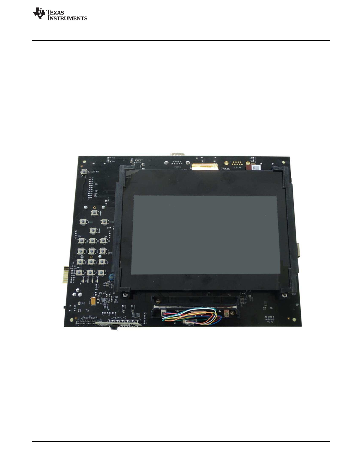
2 System View
Figure 1 and Figure 2 show the system view of the AM438x ePOS EVM.
Description
SmartReflex is a trademark of Texas Instruments.
Micron is a registered trademark of Micron.
Samtec is a registered trademark of Samtech Inc.
SPRUIF8–June 2017
Submit Documentation Feedback
Figure 1. AM438x ePOS EVM Top View
Copyright © 2017, Texas Instruments Incorporated
AM438x ePOS EVM Hardware
3
Page 4
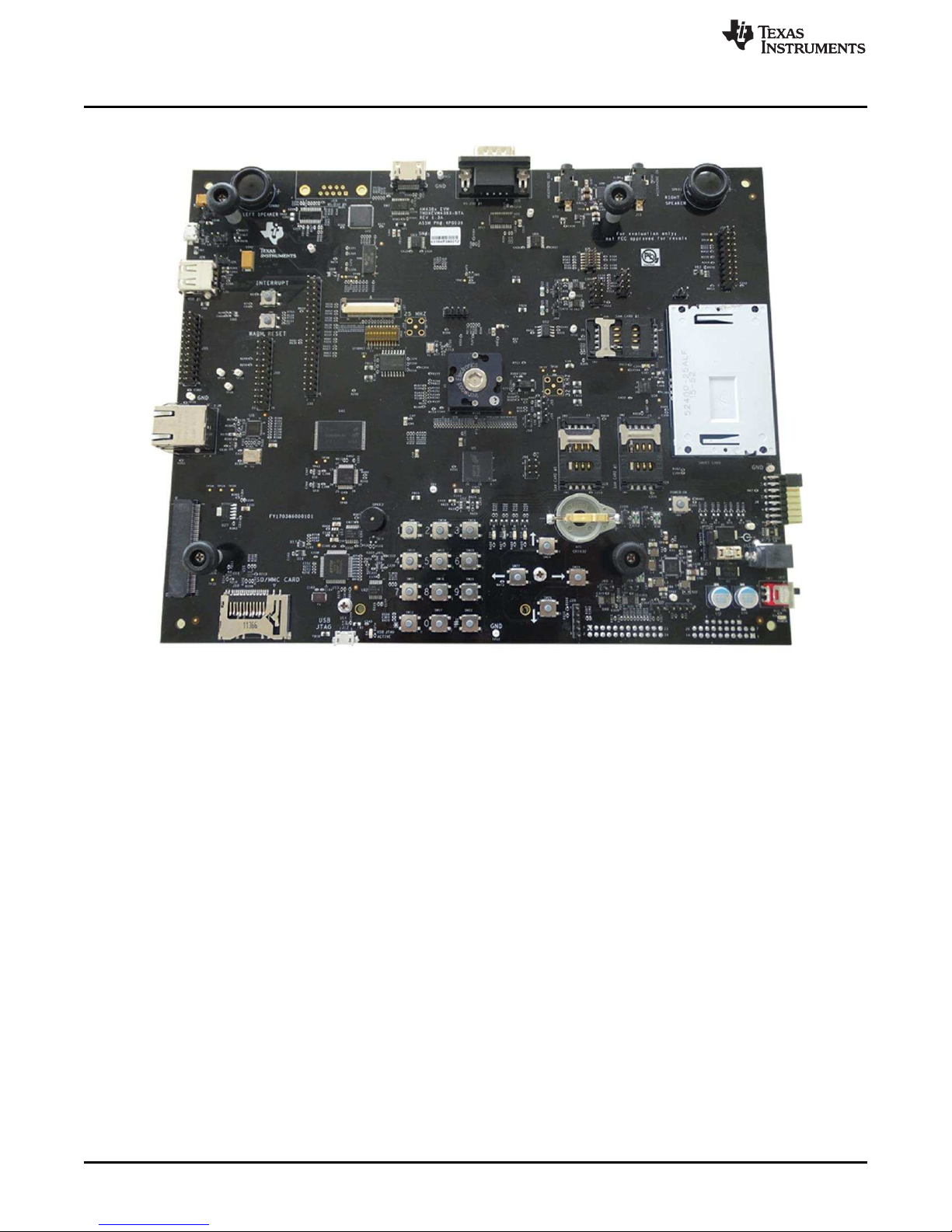
System View
www.ti.com
Figure 2. AM438x ePOS EVM Bottom View
4
AM438x ePOS EVM Hardware
Copyright © 2017, Texas Instruments Incorporated
Submit Documentation Feedback
SPRUIF8–June 2017
Page 5
SMART CARD
CONN
12X2 HDR
NAND
4GBIT
LPDDR2
8GBIT
SMART
CARD PHY
PMIC &
REGULATORS
HDMI DRVR
32 BIT
BUFFER (x2)
TWL1200
RS232 PHY
ETH PHY
AUDIO
CODEC
SPI FLASH
512MBIT
MAG STRIPE HDR
JTAG 10X2
HDR
DSS
SC, I2C
UART 0
UART 1
UART3,MMC1,
McASP0
I2C0
GPIO
McASP1
USB
DEBUG
RMII
SAM CARD
CONNX3
MICRO AB
GPIO
2X16
KEYS
TAMPER BOARD
CAMERA BOARD
7" LCD WITH CAPACITIVE TOUCH
BATTERY BOARD
8x2 HDR
USB TYPE- A
MICRO AB
COM8
CONN
J
T
A
G
U
S
B
1
U
S
B
0
C
A
M
1
Q
S
P
I
M
M
C
0
D
D
R
G
P
M
C
RS232 PHY
AM438X
www.ti.com
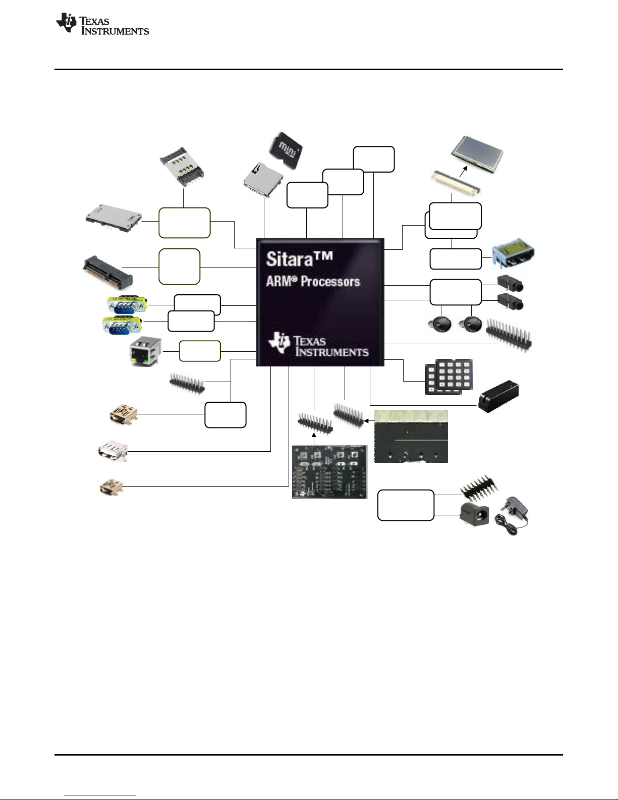
3 Functional Blocks Description
The AM438x ePOS EVM has a camera board and/or wireless add-on boards. Figure 3 shows the block
diagram of the ePOS EVM.
Functional Blocks Description
3.1 Processor
The following sections describe the major blocks of the ePOS EVM.
The AM438x processor is the central processor to this EVM. All the resources onboard surround the
AM438x processor to provide development capabilities for hardware and software. See the AM438x data
sheet and TRM for details about the processor.
System configuration signals (SYSBOOT0 to SYSBOOT18) on the EVM can be set using resistors and
switches to define some start-up parameters on the AM438x processor. See Section 5 for more details.
Figure 3. AM438x ePOS EVM Block Diagram
SPRUIF8–June 2017
Submit Documentation Feedback
Copyright © 2017, Texas Instruments Incorporated
AM438x ePOS EVM Hardware
5
Page 6

Functional Blocks Description
3.2 Clocks
Several clocks in the EVM support the AM438x processor. The main clock for the processor is derived
from a 25-MHz crystal. An onboard oscillator in the AM438x device generates the base clock and
subsequent module clocks as needed within the AM438x processor. A 32-kHz clock for the real-time clock
(RTC) on the AM438x device is derived from a 32.768-kHz crystal on the board.
The EVM also supports an option to connect an external clock using a subminiature version A (SMA)
connector for both these clocks. However, hardware modifications are needed to isolate the onboard
crystals and connect the external clock. See the schematics and TRM for details.
3.3 Reset Signals
Power-on reset to the processor is driven from the power good signal of the power manager and by a hard
reset switch. Asserting this switch also activates the reset signal SYS_RESETn, which runs to several
peripherals and the AM438x and resets those peripherals.
3.4 Memories Supported
3.4.1 LPDDR2 SDRAM
The AM438x ePOS EVM contains 8Gb (256M x 32, 2 dies) of LPDDR2 SDRAM memory from Micron®,
which has dual dies. The part number for the LPDDR2 SDRAM memory device used is
MT42L256M32D2LG-25. The package used is an 168-ball VFBGA package.
3.4.2 NAND Flash
The ePOS EVM has a NAND type of flash. The part number of the memory device used is
MT29F4G08AB, which is a 4Gb (512M × 8) of flash memory. The GPMC signals are used to
communicate with this memory.
www.ti.com
3.4.3 QSPI Flash
A QSPI flash of 512Mb, part number MX66L51235FMI-10G, is used in this design. The QSPI flash boot is
enabled through this flash. This flash is connected to the SPI0 port of the processor.
3.4.4 Board Identity Memory
Each board contains a serial EEPROM that contains board-specific data that lets the processor
automatically detect which board is connected and the version of that board. Other hardware-specific data
can be stored on this memory device as well. The part number of the memory device is CAT24C256WI-G.
See Section 5 for details on the data in this memory.
3.5 SDMMC0
The SDMMC0 connector on the ePOS EVM is a microSD card socket, part number MHC-W21-601. This
device is a standard SD/MMC card type of connector. The SDMMC0 connector is connected to the MMC0
port of the AM438x processor. Check the AM438x data sheet and TRM for supported card types and
densities.
3.6 10/100 Ethernet
The AM438x ePOS EVM uses the 10/100 Ethernet transceiver (DP83848J) from TI, which is connected to
the J8 RJ45 connector.
The reset on the transceiver is driven by the board system reset signal, SYS_RESETn, and the individual
reset signal, ETHER_RESETn, that is controlled by the GPIO of the AM438x processor. A 50-MHz crystal
oscillator drives the clock signal for the DP83848J device.
The PHY address is set to 0x10h.
6
AM438x ePOS EVM Hardware
Copyright © 2017, Texas Instruments Incorporated
Submit Documentation Feedback
SPRUIF8–June 2017
Page 7

www.ti.com
3.7 USB
The AM438x ePOS EVM supports two USB ports. The USB ports are connected to a microAB connector
and a standard type-A connector. The ESD device, TPD4S012, and common choke filter, ACM2012
(TDK), are used on the USB signals before they are connected to the AM438x pins. The ID pin of the
microAB connector can be tied to ground through a J24 jumper to look like a B device.
3.8 Connectivity
The AM438x ePOS EVM supports MCS COM8 form factor wireless boards from TI through the J21 COM
connector, which is a Samtec®card edge-type connector, part number MEC6-150-02-S-D-RA1. This
connector supports COM8 boards; more details are in the MCS COM8 board documents.
The COM connector requires 3.6 V, 442 mA on the power supply. Therefore a TPS79501 LDO regulator is
used to provide this voltage supply from the base 5.0-V supply.
The signals on the COM board are all 1.8-V voltage level. Therefore voltage translators are placed to
convert to and from 3.3 V of the AM438x rail for a particular signal that is running at 3.3 V.
3.9 UART
This EVM supports two UART ports, UART0 and UART1. The UART0 port from the processor is
converted to USB using the FT2232HL USB-to-UART bridge. UART1 is terminated on a DB9 connector
using the MAX3243 RS-232 transceiver between the AM438x and the DB9 connector. UART0 can also be
optionally terminated with a DB9 connector and a RS-232 transceiver. The RS-232 and DB9 connectors
are unpopulated on the board.
Functional Blocks Description
3.10 ADC
The analog inputs to the AM438x device are terminated on the J36 connector, where a magnetic-stripe
assembly must be connected.
3.11 Smart Card
There is a full smart card connector FCI, part number 52400-25ALF, on the EVM. There are also three
SAM card sockets onboard. A TCA5013 Smartcard PHY controls these cards and is controlled by I2C2
from the AM438x.
The PHY I2C address is set to 0x3E.
3.12 Camera
Camera interface from the AM438x processor is terminated on the 12x2 header J15. The custom-made
camera module from TI shall be interfaced with this header. This camera module is on a separate camera
board that attaches at a right angle, so that the camera can face horizontally when the ePOS EVM is
laying on a testbench.
The I2C address set to camera module is 0x30.
3.13 Audio
This EVM uses an audio codec from TI, part number TLV320AIC3111, for the audio input and output. This
audio codec is connected through the McASP1 and I2C interfaces to the AM438x. The microphone is
implemented as a 3.5-mm jack with stereo connection. Speaker out is implemented with integrated
speakers. The PUI speakers are attached to the PCB and their solder lugs are connected to the
throughhole connections for each speaker. The audio codec reset is driven by the board system reset,
SYS_RESETn, and an individual reset signal that is controlled by a GPIO of the AM438x.
3.14 Printer Header
This EVM has a 2 × 12 header to connect to an external printer. The header connects several GPIOs, SPI
buses, and PWM signals to control a printer.
SPRUIF8–June 2017
Submit Documentation Feedback
Copyright © 2017, Texas Instruments Incorporated
AM438x ePOS EVM Hardware
7
Page 8
Functional Blocks Description
3.15 Magnetic Stripe Reader
This EVM provides a 7-pin connector, part number 0533980771, to connect to the magnetic stripe reader.
The magnetic stripe reader is connected to the ADC analog inputs 0 to 7 of the AM438x processor.
4 Power Supplies
This section describes how the power supplies required for the design are generated.
4.1 Power Source
The AM438x ePOS EVM uses an external AC to +5 VDC (rated 2.5 A minimum) power adapter. The
switch near the power cable is used for powering on and off. The main power is on when the power switch
is positioned away from the power supply jack. The main power is off when the power switch is positioned
closest to the power supply jack.
4.2 Power Sequencing
The power sequencing requirements of the AM438X processor (see the AM438x data sheet) are
automatically handled by the TPS65218 PMIC.
4.3 Power-Management IC Power Supplies
The AM438x ePOS EVM uses the TPS65218 power-management IC from TI. The I2C0 on the AM438x is
used to control the SmartReflex™ port and control port on the TPS65218 device. For the AM438x
processor, the following power supplies from the TPS65218 device are used (see Table 1).
www.ti.com
Table 1. AM438x Power Supplies From TPS65218
TPS65218 Power Supply AM438x Power Rail Voltage (V)
VDCDC1 VDD_CORE 1.1 V
VDCDC2 VDD_MPU 1.1 V
VDCDC3 VDD2, VDDCA, VDDQ of LPDDR2 1.2 V
VLS1 VDD_DDR 1.2 V
VDDS_CLKOUT, VDDS_OSC, VDDS_SRAM_CORE_BG,
V1_8D
V1_0BAT VDD_TPM 1.0 V
V1_8BAT VDDS_TPM 1.8 V
V3_3D_AM438X from
TPS63031
V5_0D HDMI circuitry, USB0 power 5.0 V
VDDS_SRAM_MPU_BB VDDS_PLL_DDR, VDDS_PLL_MPU,
VDDA1P8V_USB0, VDDA1P8V_USB1, VPP, VDDA_MC_ADC, VDDA_TS_ADC,
VDDS_CTM, VDDS, VDDS_RTC, COM8, Tamper, and ADC input sections
VDDSHV 1, 2, 3, 4, 5, 6, 7, 8, 9, 10, 11 3.3 V
1.8 V
Table 2. Other Power Supplies
Power Supply Power Rail Voltage (V)
V1_8LPDDR2 from
TPS78101
V3_3D
V3_3FTDI FT2232 section from TPS79333 3.3 V
VBAT
V1_2D HDMI section power 1.2 V
VDD1 of LPDDR2 1.8 V
NAND memory, QPSI flash, Ethernet PHY, SDMMC0, board ID memory, ARM
JTAG, buffers of FTDI section, LCD buffer, touchscreen, camera module, HDMI
buffer, audio codec, RS-232 sections, COM8 sections, smart card sections,
tamper header, platform test section, GPIO header, and printer
LCD POWER generation, camera module, VCOM_BAT generation for COM8
module, USB1 power generation, platform test section, LEDs, GPIO header,
buzzer, printer
3.3 V
xx V
8
AM438x ePOS EVM Hardware
Copyright © 2017, Texas Instruments Incorporated
Submit Documentation Feedback
SPRUIF8–June 2017
Page 9

www.ti.com
4.4 APM Sense Resistors
The AM438x ePOS EVM has the following subsystems with current sense resistors (see Table 3). These
resistors allow measurement of power on each power rail, to check AM438x power requirements during
real-time software execution. The value of the resistors is selected to provide the best dynamic range
when using a TI INA226 converter. In fact, an INA226 converter is installed on the EVM for VDD_CORE,
VDD_MPU, VAM438X_DDR, V1_8D_AM438X, V3_3D_AM438X, and VDDS_DDR power supply rails of
the AM438x. Also, the measurement connections of all the sense resistors are attached to 2-pin standard
headers so that they can be read easily by a multimeter or connected to an INA226 converter EVM.
The AM438x ePOS EVM has the option to access the INA devices through the onboard AM438X I2C0
port by closing jumpers J101 and J102. By default, the INA226 converter is connected to the 5-pin header
J39. See the schematics for more details.
NOTE: The value of the sense resistors for VDD_CORE and VDD_MPU were selected to give better
dynamic range for active power modes, rather than sleep or low power modes. If power is to
be measured for VDD_CORE or VDD_MPU for sleep or low-power modes, then this sense
resistor value must be changed to give better shunt voltage values.
Voltage Net Sense Resistor Value
VDD_CORE 0.05 Ω
VDD_MPU 0.05 Ω
VAM438X_DDR 0.05 Ω
V1_8D_AM438X 0.05 Ω
V3_3D_AM438X 0.1 Ω
VDDS_DDR 0.05 Ω
Power Supplies
Table 3. AM438x ePOS EVM APM Sense Resistors
5 Configuration and Setup
5.1 Boot Configuration
SYSBOOT pins on the AM438x can be configured a certain way using a 10-bit DIP switch on the EVM.
This SYSBOOT switch configures the AM438x to different settings. For instance, the boot method of the
processor can be set up by configuring the DIP switch to particular settings. The SW48 DIP switch has the
switches that set SYSBOOT[0...4, 6, 7, 17, 18]. Other SYSBOOT pin settings are done through resistors
pulled either high or low. See the AM438x TRM and data sheet for the actual definitions of each
SYSBOOT signal. Table 4 provides the mapping of the boot strap pin and the corresponding switch bits.
DIP Switch Bits (SW48) Boot Strap
Bit 1 SYSBOOT18
Bit 2 SYSBOOT17
Bit 3 SYSBOOT7
Bit 4 SYSBOOT6
Bit 5 SYSBOOT4
Bit 6 SYSBOOT3
Bit 7 SYSBOOT2
Bit 8 SYSBOOT1
Bit 9 SYSBOOT0
Bit 10 NC (not connected)
Table 4. SYSBOOT DIP Switches
SPRUIF8–June 2017
Submit Documentation Feedback
Copyright © 2017, Texas Instruments Incorporated
AM438x ePOS EVM Hardware
9
Page 10

Configuration and Setup
When the DIP switch is on, then the corresponding SYSBOOT signal is pulled high. When the DIP switch
is off, then the corresponding SYSBOOT signal is pulled low. See the ePOS EVM schematic for more
details.
5.2 I2C Address Assignments
See the first page of the schematic for I2C device addresses.
5.3 I2C ID Memory
The ePOS EVM has a dedicated I2C EEPROM that contains specific identity and configuration information
for that board (see Table 5). In addition, there is available space in each memory for user-specific
configuration information. The part number of the memory device is CAT24C256WI-G.
Name Size (bytes) Contents
Header 4 MSB 0xEE3355AA LSB
Board name 8 Name for board in ASCII "A33515BB" = AM438x ePOS EVM
Version 4 Hardware version code for board in ASCII "1.4A" = rev. 01.4A
Serial number 12
Configuration 32
Ethernet MAC address #0 6 MAC address for AM438x Ethernet MAC #1
Ethernet MAC address #1 6 MAC address for AM438x Ethernet MAC #2 or PRU #0
Ethernet MAC address #2 6 MAC address for AM438x PRU #1 (if used)
Available 32702 Available space for other nonvolatile codes and data
www.ti.com
Table 5. AM438x ePOS EVM EEPROM Data
Serial number of the board.
This is a 12-character string: WWYY4P16nnnn, where:
• WW = 2-digit week of the year of production
• YY = 2-digit year of production
• nnnn = incrementing board number
Codes to show the configuration setup on this board. For the available EVMs
supported, the following codes are used:
• ASCII "SKU#01" = base board for general purpose EVM
• ASCII "SKU#02" = base board for industrial motor control EVM
• Remaining 26 bytes are reserved
5.4 JTAG
The AM438x ePOS EVM supports embedded XDS100V2 USB emulation using the microAB connector.
One of the FT2232 ports is used to covert these JTAG signals to USB and the other port is used for UART
signals. The ePOS EVM also has an optional 20-pin CJTAG connector from TI, to support the emulation.
Other JTAG adapters are available on TI's website and can be purchased here.
10
AM438x ePOS EVM Hardware
Copyright © 2017, Texas Instruments Incorporated
Submit Documentation Feedback
SPRUIF8–June 2017
Page 11

www.ti.com
6 User Interfaces
6.1 Keypad
The keypad has 4 × 4 push-button switches with Omron part number B3SL-1022P. The keypad is
replicated on the top and bottom of the board to allow the LCD to be swung out for hardware debugging of
the main components, or for the LCD to be mounted to the board for software debugging only. This
keypad uses 4 power lines and 4 scan lines to enable monitoring of 16 buttons. The buttons are arranged
mechanically as a standard 3 × 4 telephone dial pad and four arrow cursor directional buttons.
6.2 LEDs
There are four LEDs: red, yellow, green, and blue colors, on the top and bottom sides of the EVM. A
green power-on indication LED (D3) is available in the EVM.
6.3 Audio Buzzer
An audio buzzer is installed on the board to provide auditory cues to the user. This audio buzzer PUI
audio part number AI-1027-TWT-3V-R is driven from a GPIO.
6.4 Display
This EVM supports either LCD or HDMI display options. The AM438x DSS (display subsystem) signals
are connected to the LCD or HDMI display through the 32-bit, buffer/driver SN74LVC32244ZKE from TI.
The selection between LCD and HDMI is controlled by a GPIO of the AM438x.
User Interfaces
6.4.1 HDMI
A Silicon Image SIL9022A HDMI transmitter converts the DSS signals to HDMI. The HDMI signals are
terminated at the HDMI connector-J32, part number 10029449-001RLF. SIL9022A is controlled by I2C2
from the AM438x. The HDMI reset is driven by the board system reset SYS_RESETn and an individual
reset signal that is controlled by a GPIO of the AM438x. For more details see the schematics.
The I2C Address of SIL9022A is 0X3B.
6.4.2 LCD and Touchscreen
The LCD signals are terminated at the 50-pin FPC connector (J44), part number FH12S-50S-0.5SH. The
LCD that mates with this connector is a 7-inch, WVGA (800 × 480) 24-bit, RGB, TFT LCD panel, part
number OSD070T1718-19TS. The connector supports 27 white LEDs for backlight (controlled by one
power regulator). The LED backlight on the LCD is controlled by a TPS61081 PWM controlled LED driver.
The LCD has a capacitive touchscreen that is connected to the I2C0 port of the processor. The required
power for the LCD is generated using the TPS65105 linear regulator supply.
The I2C address of the touchscreen is 0X5C.
7 Pin Use Description
7.1 Functional Interface Mapping
A pinmux configuration file is provided to show how each pin on the AM438x is configured on the EVM.
Most interfaces on the EVM are fixed to certain functions. See the AM438x data sheet to determine other
possible pin MUX configurations, to enable different functionalities for signals that are not fixed to certain
function board connectors.
SPRUIF8–June 2017
Submit Documentation Feedback
Copyright © 2017, Texas Instruments Incorporated
AM438x ePOS EVM Hardware
11
Page 12

Board Connectors
8 Board Connectors
The pinout details of all the connectors used in the ePOS EVM are provided in the following sections.
8.1 SDMMC0 – J10
Table 6 lists the pin details of the AM438x SDMMC0 connector.
Pin No. Signal
MMC plus, MMC mobile, MMC, RS-MMC, SD#1 MMC0_D3
MMC plus, MMC mobile, MMC, RS-MMC, SD#2 MMC0_CMD
MMC plus, MMC mobile, MMC, RS-MMC, SD#3 GND
MMC plus, MMC mobile, MMC, RS-MMC, SD#4 VCC
MMC plus, MMC mobile, MMC, RS-MMC, SD#5 MMC0_CLK
MMC plus, MMC mobile, MMC, RS-MMC, SD#6 GND
MMC plus, MMC mobile, MMC, RS-MMC, SD#7 MMC0_D0
MMC plus, MMC mobile, SD#8 MMC0_D1
MMC plus, MMC mobile, SD#9 MMC0_D2
MMC plus, MMC mobile#10 NC
MMC plus, MMC mobile#11 NC
MMC plus, MMC mobile#12 NC
MMC plus, MMC mobile#13 NC
miniSD#1 MMC0_D3
miniSD#2 MMC0_CMD
miniSD#3 GND
miniSD#4 VCC
miniSD#5 MMC0_CLK
miniSD#6 GND
miniSD#7 MMC0_D0
miniSD#8 MMC0_D1
miniSD#9 MMC0_D2
miniSD#10 NC
miniSD#11 NC
www.ti.com
Table 6. AM438x SDMMC0 Connector Pin Details
8.2 LCD Connector – J44
Table 7 lists the pin details of the LCD connector.
Pin No. Signal Description
1 VLED+ Backlight power +
2 VLED+ Backlight power +
3 VLED- Backlight power –
4 VLED- Backlight power –
5 GND Ground
6 VLCD_VCOM Voltage
7 VLCD_DVDD Voltage
8 GND Ground
9 LCD_EN LCD enable
10 LCD_VSYNC LCD vertical sync
12
AM438x ePOS EVM Hardware
Table 7. AM438x LCD Connector Pin Details
SPRUIF8–June 2017
Submit Documentation Feedback
Copyright © 2017, Texas Instruments Incorporated
Page 13

www.ti.com
Board Connectors
Table 7. AM438x LCD Connector Pin Details (continued)
Pin No. Signal Description
11 LCD_HSYNC LCD horizontal sync
12 LCD_BLUE7 LCD blue data 7
13 LCD_BLUE6 LCD blue data 6
14 LCD_BLUE5 LCD blue data 5
15 LCD_BLUE4 LCD blue data 4
16 LCD_BLUE3 LCD blue data 3
17 LCD_BLUE2 LCD blue data 2
18 LCD_BLUE1 LCD blue data 1
19 LCD_BLUE0 LCD blue data 0
20 LCD_GREEN7 LCD green data 7
21 LCD_GREEN6 LCD green data 6
22 LCD_GREEN5 LCD green data 5
23 LCD_GREEN4 LCD green data 4
24 LCD_GREEN3 LCD green data 3
25 LCD_GREEN2 LCD green data 2
26 LCD_GREEN1 LCD green data 1
27 LCD_GREEN0 LCD green data 0
28 LCD_RED7 LCD red data 7
29 LCD_RED6 LCD red data 6
30 LCD_RED5 LCD red data 5
31 LCD_RED4 LCD red data 4
32 LCD_RED3 LCD red data 3
33 LCD_RED2 LCD red data 2
34 LCD_RED1 LCD red data 1
35 LCD_RED0 LCD red data 0
36 GND Ground
37 LCD_PCLK Clock
38 GND Ground
39 LCD_LEFTRIGHT Left-right scan direction select
40 LCD_UPDOWN Up-down scan direction select
41 VLCD_VGH Voltage high
42 VLCD_VGL Voltage low
43 VLCD_AVDD Voltage analog
44 LCD_RESETn Reset
45 NC NC
46 VLCD_VCOM Voltage
47 LCD_DITHER Dither
48 GND Ground
49 NC NC
50 NC NC
SPRUIF8–June 2017
Submit Documentation Feedback
Copyright © 2017, Texas Instruments Incorporated
AM438x ePOS EVM Hardware
13
Page 14

Board Connectors
8.3 Touch Connector – J45
Table 8 lists the pin details of the LCD capacitive touchscreen connector.
Pin No. Direction Description
1 NC NC
2 NC NC
3 TSC_INTn Touchscreen interrupt
4 GP_I2C_SDA I2C data
5 GP_I2C_SCK I2C clock
6 SYS_RESETn Reset
7 GND Ground
8 VCC Power
8.4 Ethernet – J8
Table 9 lists the pin details of the AM438x 10/100 Ethernet connector.
Pin No. Signal Name Description
1 ETHER1_RDP Data 1 RX positive
2 ETHER1_RDN Data 1 RX negative
3 VCC Voltage
4 VCC Voltage
5 ETHER1_TDP Data 1 TX positive
6 ETHER1_TDP Data 1 TX negative
7 NC NC
8 DGND Ground
D1 LINK LED ANODE Anode of link LED
D2 LINK LED CATHODE Cathode of link LED
D3 SPEED LED ANODE Anode of speed LED
D4 SPEED LED CATHODE Cathode of speed LED
SHLD1 DGND Ground
SHLD2 DGND Ground
www.ti.com
Table 8. LCD Capacitive Touchscreen Pin Details
Table 9. AM438x 10/100 Ethernet Pin Details
8.5 USB
8.5.1 Micro AB Connector – J23
Table 10 lists pin details of the AM438x micro AB connector.
Table 10. AM438x Micro AB Connector – USB Port 0 Pin Details
Pin No. Signal Name Description
1 VUSB_VBUS0 USB0 bus voltage
2 USB0_CONN_DM USB0 data minus
3 USB0_CONN_DP USB0 data plus
4 USB0_ID USB0 identification
5 DGND Ground
14
AM438x ePOS EVM Hardware
Copyright © 2017, Texas Instruments Incorporated
Submit Documentation Feedback
SPRUIF8–June 2017
Page 15

www.ti.com
8.5.2 Type A Connector – J26
Table 11 lists pin details of the AM438x type A connector.
Table 11. AM438x Type A Connector – USB Port 1 Pin Details
Pin No. Signal Name Description
1 VUSB_VBUS1 USB1 bus voltage
2 USB1_CONN_DM USB1 data minus
3 USB1_CONN_DP USB1 data plus
4 DGND Ground
8.6 Camera Interface Header – J15
Table 12 lists the pin details of the camera interface header connector.
Table 12. Camera Interface Header Pin Details
Pin No. Signal Name Description
1 VBAT Power supply VBAT
2 CAM1_VSYNC Vertical sync
3 CAM1_DATA0 Data 1
4 CAM1_HSYNC Horizontal sync
5 CAM1_DATA1 Data 1
6 CAM1_DATA6 Data 6
7 CAM1_DATA2 Data 2
8 CAM1_DATA7 Data 7
9 CAM1_PCLK Clock
10 CAM1_DATA8 Data 8
11 GND Ground
12 GND Ground
13 CAM1_DATA3 Data 3
14 CAM1_DATA9 Data 9
15 CAM1_DATA4 Data 4
16 CAM1_GIO0 GPIO 0
17 CAM1_DATA5 Data 5
18 CAM1_BUF_EN Buffer enable
19 CAM1_WEN Write enable
20 CAM1_FIELD Field
21 GND Ground
22 CAM1_I2C_SCL I2C clock
23 CAM1_SRCCLK Clock
24 CAM1_I2C_DTA I2C data
Board Connectors
SPRUIF8–June 2017
Submit Documentation Feedback
Copyright © 2017, Texas Instruments Incorporated
AM438x ePOS EVM Hardware
15
Page 16

Board Connectors
8.7 HDMI Header Connector – J32
Table 13 lists the pin details of the HDMI header connecter.
Pin No. Signal Name Description
1 HDMI_TX2+ Data Transmit2 +ve
2 DAT2_S Data 2 GND
3 HDMI_TX2- Data Transmit2 -ve
4 HDMI_TX1+ Data Transmit1 +ve
5 DAT1_S Data 1 GND
6 HDMI_TX1- Data Transmit1 -ve
7 HDMI_TX0+ Data Transmit0 +ve
8 DAT0_S Data 0 GND
9 HDMI_TX0- Data Transmit0 -ve
10 CLK+ Clock +ve
11 Clock_S Clock GND
12 Clock- Clock -ve
13 HDMICONN_CEC CEC
14 NC NC
15 HDMICONN_I2CSCL I2C clock
16 HDMICONN_I2CSDA I2C data
17 GND Ground
18 V5_0HDMICONN Voltage
19 HDMICONN_HPLG HPLG
www.ti.com
Table 13. HDMI Header Pin Details
8.8 RS-232 Connectors
8.8.1 RS-232 Connector 1 – J19
Table 14 lists the pin details of RS-232 connector 1 (not mounted).
Pin No. Signal Name Description
1 NC NC
2 RS232_0_RXD Receive
3 RS232_0_TXD Transmit
4 NC NC
5 GND Ground
6 NC NC
7 RS232_0_RTS Request to send
8 RS232_0_CTS Clear to send
9 NC NC
Table 14. RS-232 Connector 1 Pin Details
16
AM438x ePOS EVM Hardware
Copyright © 2017, Texas Instruments Incorporated
Submit Documentation Feedback
SPRUIF8–June 2017
Page 17

www.ti.com
8.8.2 RS-232 Connector 2 – J20
Table 15 lists the pin details of RS-232 connector 2.
Table 15. RS-232 Connector 2 Pin Details
Pin No. Signal Name Description
1 RS232_1_DCD Data carrier detect
2 RS232_1_RXD Receive
3 RS232_1_TXD Transmit
4 RS232_1_DTR Data terminal ready
5 GND Ground
6 RS232_1_DSR Data set ready
7 RS232_1_RTS Request to send
8 RS232_1_CTS Clear to send
9 RS232_1_RI Ring indicator
8.9 Smart Card Connector – J27
Table 16 lists the pin details of the smart card connector.
Table 16. Smart Card Connector Pin Details
Pin Name Signal Name Description
Sensor1 SMRTCRD1_PRES Smart card present
Sensor2 V3_3D Voltage 3.3 V
T1 VCC_SC1 Voltage
T2 SMRTCRD1_RST Reset
T3 SMRTCRD1_CLK Clock
T4 SMRTCRD1_C4 Auxillary I/O
T5 GND Ground
T6 VCC_SC1 Voltage
T7 SMRTCRD1_IO I/O
T8 SMRTCRD1_C8 Auxillary I/O
Board Connectors
8.10 SAM Card Connector – J28, J29, and J58
Three SAM card connectors are used in this ePOS EVM design. Table 17 lists the pinout details of the
SAM card connector.
Pin Name Signal Name Description
C1 VCC_SC2 Voltage
C2 SAMCRD_RST Smart card reset
C3 SAMCRD_CLK Smart card clock
C5 GND Ground
C6 VCC_SC2 Voltage
C7 SAMCRD_IO I/O
SW1 NC NC
SW2 NC NC
SPRUIF8–June 2017
Submit Documentation Feedback
Table 17. SAM Card Connector Pin Details
Copyright © 2017, Texas Instruments Incorporated
AM438x ePOS EVM Hardware
17
Page 18

Board Connectors
8.11 Tamper Header – J34
Table 18 lists the pin details of the tamper header.
Pin No. Signal Name Description
1 V1_8BAT Voltage 1.8 V
2 V3_3D Voltage 3.3 V
3 GND Reserved
4 RESERVED5 Tamper event signal
5 TM_PIO_0 I/O 0
6 TM_PIO_1 I/O 1
7 TM_PIO_2 I/O 2
8 TM_PIO_3 I/O 3
9 RESERVED1 Reserved
10 TPMSS_OUT TPMSS_out signal
11 TM_PIO_8 I/O 8
12 TM_PIO_9 I/O 9
13 TM_PIO_10 I/O 10
14 TM_PIO_11 I/O 11
15 RESERVED3 Reserved
16 RESERVED4 Reserved
17 NC NC
18 NC NC
19 RTC_ALARM RTC alarm
20 GND Ground
www.ti.com
Table 18. Tamper Header Pin Details
18
AM438x ePOS EVM Hardware
Copyright © 2017, Texas Instruments Incorporated
Submit Documentation Feedback
SPRUIF8–June 2017
Page 19

www.ti.com
8.12 Platform Test Header – J35
Table 19 lists the pin details of the platform test header.
Pin No. Signal Name Description
1 VBAT Voltage V
2 DGND Digital ground
3 VBAT Voltage V
4 DGND Digital ground
5 V3_3D Voltage 3.3 V
6 DGND Digital ground
7 GPIO5_4 GPIO
8 GPIO5_9 GPIO
9 DGND Digital ground
10 GPIO5_10 GPIO
11 GPIO5_6 GPIO
12 DGND Digital ground
13 GPIO5_7 GPIO
14 GPIO5_11 GPIO
15 DGND Digital ground
16 GPIO5_12 GPIO
17 GPIO5_8 GPIO
18 GPIO5_5 GPIO
19 GPIO5_13 GPIO
20 AM438X_AIN5 Analog input 5
21 GNDA_ADC Analog ground
22 AM438X_AIN4 Analog input 4
23 VDDA_ADC Voltage ADC
24 AM438X_AIN3 Analog input 3
Board Connectors
Table 19. Platform Test Header Pin Details
BAT
BAT
SPRUIF8–June 2017
Submit Documentation Feedback
Copyright © 2017, Texas Instruments Incorporated
AM438x ePOS EVM Hardware
19
Page 20

Board Connectors
8.13 Magnetic Stripe Reader Header – J36
Table 20 lists the pin details of the magnetic stripe reader header.
Table 20. Magnetic Stripe Reader Header Pin Details
Pin No. Signal Name Description
1 AM438X_MAGAIN0 Magnetic-stripe reader analog input 0
2 AM438X_MAGAIN1 Magnetic-stripe reader analog input 1
3 AM438X_MAGAIN2 Magnetic-stripe reader analog input 2
4 AM438X_MAGAIN3 Magnetic-stripe reader analog input 3
5 AM438X_MAGAIN4 Magnetic-stripe reader analog input 4
6 AM438X_MAGAIN5 Magnetic-stripe reader analog input 5
7 GNDA_MAG Analog ground
8.14 ADC Input Header – J37
Table 21 lists the pin details of the ADC input header.
Table 21. ADC Input Header Pin Details
Pin No. Signal Name Description
1 MON_AIN0 Monitoring analog input 0
2 MON_AIN4 Monitoring analog input 4
3 MON_AIN1 Monitoring analog input 1
4 MON_AIN5 Monitoring analog input 5
5 GND_ADC Analog ground
6 V1_8D Voltage 1.8 V
7 MON_AIN2 Monitoring analog input 2
8 MON_AIN6 Monitoring analog input 6
9 MON_AIN3 Monitoring analog input 3
10 MON_AIN7 Monitoring analog input 7
11 GND_ADC Analog ground
12 GND_ADC Analog ground
www.ti.com
20
AM438x ePOS EVM Hardware
Copyright © 2017, Texas Instruments Incorporated
Submit Documentation Feedback
SPRUIF8–June 2017
Page 21

www.ti.com
8.15 GPIO Header – J38
Table 22 lists the pin details of the GPIO header.
Pin No. Signal Name Description
1 V3_3D Voltage 3.3 V
2 VBAT Voltage V
3 GPIO0 General-purpose I/O 0
4 NC NC
5 GPIO1 General-purpose I/O 1
6 NC NC
7 GPIO2 General-purpose I/O 2
8 NC NC
9 GPIO3 General-purpose I/O 3
10 NC NC
11 GPIO4 General-purpose I/O 4
12 NC NC
13 GPIO5 General-purpose I/O 5
14 NC NC
15 GPIO6 General-purpose I/O 6
16 NC NC
17 GPIO7 General-purpose I/O 7
18 NC NC
19 GPIO8 General-purpose I/O 8
20 NC NC
21 GPIO9 General-purpose I/O 9
22 NC NC
23 GPIO10 General-purpose I/O 10
24 NC NC
25 GPIO11 General-purpose I/O 11
26 NC NC
27 GPIO12 General-purpose I/O 12
28 NC NC
29 GPIO13 General-purpose I/O 13
30 NC NC
31 GPIO14 General-purpose I/O 14
32 NC NC
33 GPIO15 General-purpose I/O 15
34 NC NC
35 GPIO16 General-purpose I/O 16
36 NC NC
37 GPIO17 General-purpose I/O 17
38 NC NC
39 DGND Ground
40 DGND Ground
Board Connectors
Table 22. GPIO Header Pin Details
BAT
SPRUIF8–June 2017
Submit Documentation Feedback
Copyright © 2017, Texas Instruments Incorporated
AM438x ePOS EVM Hardware
21
Page 22

Board Connectors
8.16 Printer Header – J90
Table 23 lists the pin details of the printer header.
Pin No. Signal Name Description
1 VBAT Voltage V
2 V3_3D Voltage 3.3 V
3 VBAT Voltage V
4 eHRPWM0_A PWM signal 0 – A
5 PRINTER_GPIO3 General-purpose I/O 3
6 eHRPWM0_B PWM signal 0 – B
7 PRINTER_GPIO2 General-purpose I/O 2
8 eHRPWM0_TRIPZONE PWM signal 0 Trip Zone
9 PRINTER_GPIO1 General-purpose I/O 1
10 eHRPWM0_SYNCI PWM 0 Sync
11 PRINTER_GPIO0 General-purpose I/O 0
12 eHRPWM1_A PWM 1 – A
13 DGND Ground
14 eHRPWM1_B PWM 1 – B
15 PRINT_SPI_CLK SPI clock
16 DGND Ground
17 PRINT_SPI_CSn SPI chip select
18 NC NC
19 PRINT_SPI_MOSI SPI master out slave in
20 NC NC
21 PRINT_SPI_MISO SPI master in slave out
22 NC NC
23 DGND Ground
24 NC NC
www.ti.com
Table 23. Printer Header Pin Details
BAT
BAT
22
AM438x ePOS EVM Hardware
Copyright © 2017, Texas Instruments Incorporated
Submit Documentation Feedback
SPRUIF8–June 2017
Page 23

www.ti.com
8.17 SPI Headers
8.17.1 SPI Header 1 – J31
Table 24 lists the pin details of SPI header 1.
Pin No. Signal Name Description
1 V3_3D 3.3-V supply
2 DGND Ground
3 AM438X_SPI0_SCLK SPI0 clock
4 AM438X_SPI0_DIN SPI0 data in
5 AM438X_SPI0_DOUT SPI0 data out
6 AM438X_SPI0_CS0 SPI0 chip select
7 DGND Ground
8 NC NC
8.17.2 SPI Header 2 – J30
Table 25 lists the pin details of SPI header 2.
Board Connectors
Table 24. SPI - Header 1 Pin Details
Table 25. SPI - Header 2 Pin Details
Pin No. Signal Name Description
1 V3_3D 3.3-V supply
2 DGND Ground
3 AM438X_SPI1_SCLK SPI1 clock
4 AM438X_SPI1_D1 SPI1 D1
5 AM438X_SPI1_D0 SPI1_D0
6 AM438X_SPI1_CS0n SPI1 chip select
7 DGND Ground
8 AM438X_STATUS_LED1 Status LED1
8.18 I2C Header – J39
Table 26 lists the pin details of the I2C header.
Pin No. Signal Name Description
1 PWRMON_I2CSCL I2C clock
2 PWRMON_I2CSDA I2C data
3 DGND Ground
4 PM_ALERT Alert
5 NC NC
Table 26. I2C - Header Pin Details
SPRUIF8–June 2017
Submit Documentation Feedback
Copyright © 2017, Texas Instruments Incorporated
AM438x ePOS EVM Hardware
23
Page 24

Board Connectors
8.19 Automation Header – J97
Table 27 lists the pin details of the automation header.
Pin No. Signal Name Description
1 V3_3D Voltage 3.3 V
2 V3_3D Voltage 3.3 V
3 V3_3D Voltage 3.3 V
4 NC NC
5 NC NC
6 NC NC
7 DGND Ground
8 SYSBOOT0 Boot strap bit 0
9 SYSBOOT1 Boot strap bit 1
10 SYSBOOT2 Boot strap bit 2
11 SYSBOOT3 Boot strap bit 3
12 SYSBOOT4 Boot strap bit 4
13 SYSBOOT6 Boot strap bit 6
14 SYSBOOT7 Boot strap bit 7
15 SYSBOOT17 Boot strap bit 17
16 DGND Ground
17 SYSBOOT18 Boot strap bit 18
18 NC NC
19 NC NC
20 NC NC
21 NC NC
22 NC NC
23 NC NC
24 NC NC
25 DGND Ground
26 NC NC
27 TEST_PORZn Reset signal
28 NC NC
29 TEST_WARMRESETn Reset signal
30 NC NC
31 NC NC
32 TEST_GPIO17 GPIO
33 NC NC
34 DGND Ground
35 NC NC
36 PWRMON_I2CSCL Power monitor I2C clock
37 NC NC
38 PWRMON_I2CSDA Power monitor I2C data
39 NC NC
40 DGND Ground
www.ti.com
Table 27. Automation - Header Pin Details
9 EVM Important Notices
The standard terms and conditions for TI Evaluation Modules can be downloaded here.
24
AM438x ePOS EVM Hardware
Copyright © 2017, Texas Instruments Incorporated
Submit Documentation Feedback
SPRUIF8–June 2017
Page 25

IMPORTANT NOTICE FOR TI DESIGN INFORMATION AND RESOURCES
Texas Instruments Incorporated (‘TI”) technical, application or other design advice, services or information, including, but not limited to,
reference designs and materials relating to evaluation modules, (collectively, “TI Resources”) are intended to assist designers who are
developing applications that incorporate TI products; by downloading, accessing or using any particular TI Resource in any way, you
(individually or, if you are acting on behalf of a company, your company) agree to use it solely for this purpose and subject to the terms of
this Notice.
TI’s provision of TI Resources does not expand or otherwise alter TI’s applicable published warranties or warranty disclaimers for TI
products, and no additional obligations or liabilities arise from TI providing such TI Resources. TI reserves the right to make corrections,
enhancements, improvements and other changes to its TI Resources.
You understand and agree that you remain responsible for using your independent analysis, evaluation and judgment in designing your
applications and that you have full and exclusive responsibility to assure the safety of your applications and compliance of your applications
(and of all TI products used in or for your applications) with all applicable regulations, laws and other applicable requirements. You
represent that, with respect to your applications, you have all the necessary expertise to create and implement safeguards that (1)
anticipate dangerous consequences of failures, (2) monitor failures and their consequences, and (3) lessen the likelihood of failures that
might cause harm and take appropriate actions. You agree that prior to using or distributing any applications that include TI products, you
will thoroughly test such applications and the functionality of such TI products as used in such applications. TI has not conducted any
testing other than that specifically described in the published documentation for a particular TI Resource.
You are authorized to use, copy and modify any individual TI Resource only in connection with the development of applications that include
the TI product(s) identified in such TI Resource. NO OTHER LICENSE, EXPRESS OR IMPLIED, BY ESTOPPEL OR OTHERWISE TO
ANY OTHER TI INTELLECTUAL PROPERTY RIGHT, AND NO LICENSE TO ANY TECHNOLOGY OR INTELLECTUAL PROPERTY
RIGHT OF TI OR ANY THIRD PARTY IS GRANTED HEREIN, including but not limited to any patent right, copyright, mask work right, or
other intellectual property right relating to any combination, machine, or process in which TI products or services are used. Information
regarding or referencing third-party products or services does not constitute a license to use such products or services, or a warranty or
endorsement thereof. Use of TI Resources may require a license from a third party under the patents or other intellectual property of the
third party, or a license from TI under the patents or other intellectual property of TI.
TI RESOURCES ARE PROVIDED “AS IS” AND WITH ALL FAULTS. TI DISCLAIMS ALL OTHER WARRANTIES OR
REPRESENTATIONS, EXPRESS OR IMPLIED, REGARDING TI RESOURCES OR USE THEREOF, INCLUDING BUT NOT LIMITED TO
ACCURACY OR COMPLETENESS, TITLE, ANY EPIDEMIC FAILURE WARRANTY AND ANY IMPLIED WARRANTIES OF
MERCHANTABILITY, FITNESS FOR A PARTICULAR PURPOSE, AND NON-INFRINGEMENT OF ANY THIRD PARTY INTELLECTUAL
PROPERTY RIGHTS.
TI SHALL NOT BE LIABLE FOR AND SHALL NOT DEFEND OR INDEMNIFY YOU AGAINST ANY CLAIM, INCLUDING BUT NOT
LIMITED TO ANY INFRINGEMENT CLAIM THAT RELATES TO OR IS BASED ON ANY COMBINATION OF PRODUCTS EVEN IF
DESCRIBED IN TI RESOURCES OR OTHERWISE. IN NO EVENT SHALL TI BE LIABLE FOR ANY ACTUAL, DIRECT, SPECIAL,
COLLATERAL, INDIRECT, PUNITIVE, INCIDENTAL, CONSEQUENTIAL OR EXEMPLARY DAMAGES IN CONNECTION WITH OR
ARISING OUT OF TI RESOURCES OR USE THEREOF, AND REGARDLESS OF WHETHER TI HAS BEEN ADVISED OF THE
POSSIBILITY OF SUCH DAMAGES.
You agree to fully indemnify TI and its representatives against any damages, costs, losses, and/or liabilities arising out of your noncompliance with the terms and provisions of this Notice.
This Notice applies to TI Resources. Additional terms apply to the use and purchase of certain types of materials, TI products and services.
These include; without limitation, TI’s standard terms for semiconductor products http://www.ti.com/sc/docs/stdterms.htm), evaluation
modules, and samples (http://www.ti.com/sc/docs/sampterms.htm).
Mailing Address: Texas Instruments, Post Office Box 655303, Dallas, Texas 75265
Copyright © 2017, Texas Instruments Incorporated
 Loading...