

TESTO 300, 300 LL Instruction Manual

testo 300 / testo 300 LL - Combustion Analyzer
Instruction manual
www. .com
information@itm.com1.800.561.8187

Contents
1
2
3
4
5
6
7
8
Contents
About this document ................................................................................... 7
1.1 Symbols ................................................................................................. 7
1.2 Warning notices ...................................................................................... 7
Safety and disposal ..................................................................................... 8
Product-specific safety instructions .......................................................... 8
Authorizations and certification ................................................................. 8
Specifications ............................................................................................... 9
Product description ................................................................................... 10
6.1 Front view ............................................................................................. 10
6.2 Rear view ............................................................................................. 11
6.3 Connections ......................................................................................... 11
6.4 Compact flue gas probe ....................................................................... 12
6.5 Modular flue gas probe ......................................................................... 12
First steps ................................................................................................... 13
7.1 Commissioning ..................................................................................... 13
7.2 Power supply / Battery ......................................................................... 13
7.2.1 Charge battery ....................................................................... 13
7.2.2 Power Supply (AC) operation ................................................ 14
7.3 Touchscreen operating concept ........................................................... 14
7.4 Keypad ................................................................................................. 15
7.5 Switch instrument on and off ................................................................ 16
7.6 Connect probes .................................................................................... 17
Using the product ...................................................................................... 18
8.1 User interface ....................................................................................... 18
8.1.1 Main measurement display - List ........................................... 19
8.1.2 Main measurement display - Graphics .................................. 20
8.1.3 Main measurement display - Hot Spot ................................... 21
8.2 Overview of main menu ( ) ............................................................. 22
8.2.1 Customer / Measuring site (point) .......................................... 23
8.2.2 Tests ...................................................................................... 26
8.2.3 Saved reports ........................................................................ 27
8.2.4 Gas path check ...................................................................... 29
www. .com
information@itm.com1.800.561.8187

Contents
9
8.2.5 Device settings ...................................................................... 29
8.2.5.1 Country version and language ............................. 29
8.2.5.2 Wi-Fi ..................................................................... 31
8.2.5.3 Date/Time ............................................................. 32
8.2.5.4 My company address ........................................... 34
8.2.5.5 Bluetooth .............................................................. 35
8.2.5.6 Hotspot ................................................................. 35
8.2.5.7 Display Brightness ............................................... 35
8.2.5.8 CO/NO sensor protect .......................................... 36
8.2.5.9 O2 Reference ....................................................... 36
8.2.5.10 Alarm limits ........................................................... 36
8.2.6 Sensor Diagnosis .................................................................. 37
8.2.7 Error List ............................................................................... 37
8.2.8 Device Information ................................................................ 37
8.2.9 Server Information................................................................. 37
8.2.10 E-mail .................................................................................... 37
8.2.11 My Apps ................................................................................ 39
8.2.12 Help ....................................................................................... 40
8.2.12.1 Please register your testo 300 .............................. 40
8.2.12.2 Tutorial ................................................................. 40
8.2.12.3 Setup Wizard ........................................................ 40
8.2.12.4 Update via USB .................................................... 41
Performing the measurement ................................................................... 42
9.1 Prepare for measurement .................................................................... 42
9.2 Zeroing phases .................................................................................... 42
9.3 Carry out gas path check ..................................................................... 43
9.4 Use of flue gas probe ........................................................................... 43
9.5 Overview of measurement types ( ) ............................................ 44
9.6 Overview of options ( ) ................................................................. 45
9.6.1 Configure measurement display ........................................... 46
9.6.2 Flue Gas Analysis ................................................................. 48
9.6.3 Draft-Measurement ............................................................... 49
9.6.4 CO Air free ............................................................................ 50
www. .com
information@itm.com1.800.561.8187

10
11
Contents
9.6.5 Smoke Number ...................................................................... 50
9.6.6 Differential pressure ............................................................... 51
9.6.7 Differential temperature ......................................................... 51
9.6.8 O2 air (EU regulation) ............................................................ 52
9.6.9 Clock Meter ........................................................................... 52
9.6.10 Oil flow calculation ................................................................. 53
9.6.11 CO Ambient ........................................................................... 53
9.6.12 Pipe Commissioning (EU regulation) ..................................... 54
9.6.13 Pressure Drop test (EU regulation) ........................................ 55
9.6.14 Pretest (EU regulation) .......................................................... 57
9.7 Overview of tests ( ) ...................................................................... 58
9.7.1 Print values ............................................................................ 58
9.7.2 Save ...................................................................................... 59
9.7.3 Finish test .............................................................................. 59
Maintenance ............................................................................................... 62
10.1 Service ................................................................................................. 62
10.2 Calibration ............................................................................................ 62
10.3 Check instrument status ....................................................................... 62
10.3.1 Sensor diagnosis ................................................................... 62
10.3.2 Error list ................................................................................. 62
10.4 Clean the measuring instrument .......................................................... 63
10.5 Drain condensate trap .......................................................................... 63
10.6 Open the measuring instrument ........................................................... 65
10.7 Replace sensors ................................................................................... 66
10.7.1 Replace O2 sensor ................................................................ 67
10.7.2 Change CO, CO H2 and NO sensor ...................................... 68
10.8 Clean modular flue gas probe .............................................................. 69
10.9 Replace the probe module ................................................................... 69
10.10 Check/replace particle filter ............................................................... 69
10.11 Replace thermocouple ...................................................................... 71
Technical data ............................................................................................ 72
11.1 Contact and support ............................................................................. 73
www. .com
information@itm.com1.800.561.8187
1
1.1
Note: basic or additional information
…
Result of an action
Requirement
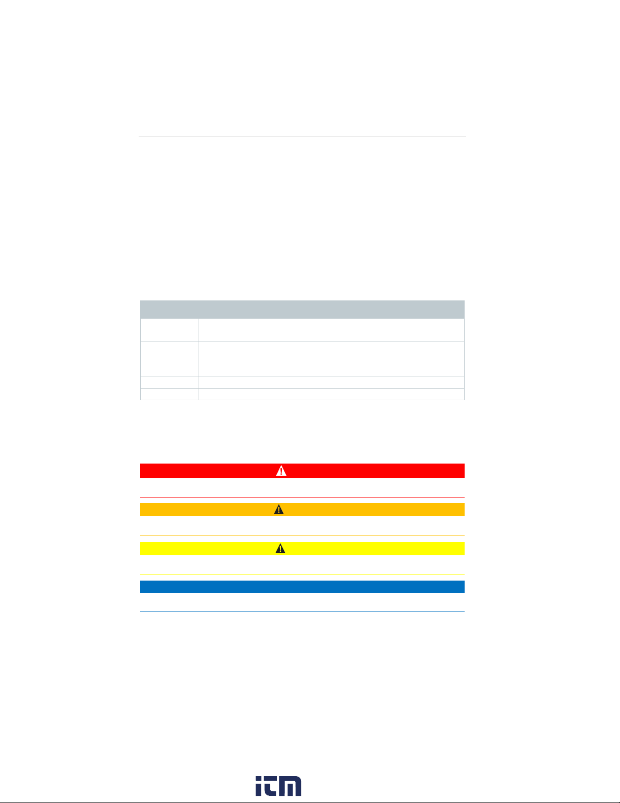
1.2
Risk of death!
Indicates possible serious injury.
Indicates possible minor injury.
CAUTION
Indicates possible damage to equipment.
1 About this document
About this document
• The instruction manual is an integral part on the instrument.
• Keep this documentation to hand so that you can refer to it when necessary.
• Please read this instruction manual carefully and familiarize yourself with the
product before use.
• Hand this instruction manual on to any other users of the product.
• Pay attention to the safety instructions and warning advice in order to
prevent injury and damage to the product.
Symbols
Display Explanation
1
Action: several steps, the sequence must be followed.
2
Warning notices
Always pay attention to any information marked with the following warning
notices along with warning pictograms. Implement the specified precautionary
measures!
DANGER
WARNING
CAUTION
www. .com
7
information@itm.com1.800.561.8187

2
3
-
Dangerous mixture of gases
Danger of explosion!
-
-
4
2 Safety and disposal
Safety and disposal
Take the testo information document into account (accompanies the product).
Product-specific safety instructions
CAUTION
The condensate may be acidic.
Risk of burns to the hands!
Wear acid-resistant safety gloves, glasses and overalls to empty the
condensate.
• Make sure that the condensate has been fully emptied out of the condensate
trap before the measuring instrument is stored for a long time.
• Before disposing of the product, the condensate trap must be emptied and
the condensate in the crude gas tube disposed of in a suitable container.
• When testing a gas pipe, pay attention to the following:
WARNING
Make sure there are no leaks between the sampling point and the measuring
instrument.
Do not smoke or use open flames during the measurement.
Authorizations and certification
Please find the current country approvals in the Approval and Certification
document which is enclosed with the product.
8
www. .com
information@itm.com1.800.561.8187

5
5 Specifications
Specifications
The testo 300 is a measuring instrument for flue gas analysis on applications,
such as
• residential, commercial and industrial applications (oil, gas, wood, coal)
• low-temperature and condensing boilers
• boilers, furnaces and gas heaters.
Using the instrument, these systems can be adjusted and checked for
applicable limit values.
The instrument has been verified as a short-term measuring instrument and
should not be used as a safety (alarm) device.
The following tasks can also be performed using the instrument:
• Checking the O
ensure optimum operation.
• Draft measurement.
• Measuring the gas flow pressure in gas heaters.
• Measuring and optimizing the flow and return temperatures of heating
systems.
• Measuring the CO concentration in the ambient air.
A NO
filter for the CO sensor can be ordered as a spare part to replace a used
x
filter.
, CO and CO2, NO, NOx values in combustion plants to
2
www. .com
9
information@itm.com1.800.561.8187

6
6.1
1
USB interface/
power connection
4
User interface
2
Gas outlet
5
Condensate trap
3
On/Off button
6
Connections
6 Product description
Product description
Front view
10
www. .com
information@itm.com1.800.561.8187

6.2
1
Attachment point for carrying
strap
2
Magnets
6.3
1
Probe connections for additional
probes
3
Flue gas socket
2
Integrated ambient air probe
4
Differential pressure
measurement connection
There must be no more than one extension lead (0554 1202)
Rear view
6 Product description
Connections
connected between flue gas socket and flue gas probe.
11
www. .com
information@itm.com1.800.561.8187

6.4
window and particle filter
instrument
2
Probe handle
4
Connection cable
6.5
Removable filter chamber with
window and particle filter
Connector plug for measuring
instrument
2
Lock release
5
Probe handle
6 Product description
Compact flue gas probe
1 Removable filter chamber with
Modular flue gas probe
1
3 Connector plug for measuring
4
3 Probe module 6 Connection cable
12
www. .com
information@itm.com1.800.561.8187

7
7.1
7.2
, the measuring instrument is automatically powered via the
Storage conditions for the energy storage unit:
7.2.1
1
Connect the instrument plug of the power supply to the power supply
2
Connect the power plug of the power supply to an outlet.
If the battery has discharged completely, the charging time at room
7 First steps
First steps
Commissioning
Take the information in the testo information document (included with the
product) into account for this.
Power supply / Battery
The measuring instrument is supplied with a rechargeable battery.
Fully charge the battery before use.
If plugged in
power supply.
Only charge the battery at an ambient temperature of 32 to 95°F.
• Ambient temperature from 50 to 68°F
• Charge level of 50 to 80%
Charge battery
socket on the measuring instrument.
The charging process starts. LED in
the condensate trap flashes red.
The charging process stops
automatically when battery is fully
charged. LED in the condensate trap
has a continuous red light.
temperature is approx. 5-6 hrs.
13
www. .com
information@itm.com1.800.561.8187
7.2.2
1
Connect the instrument plug of the power supply to the power supply
2
Connect the power plug of the power supply to an outlet.
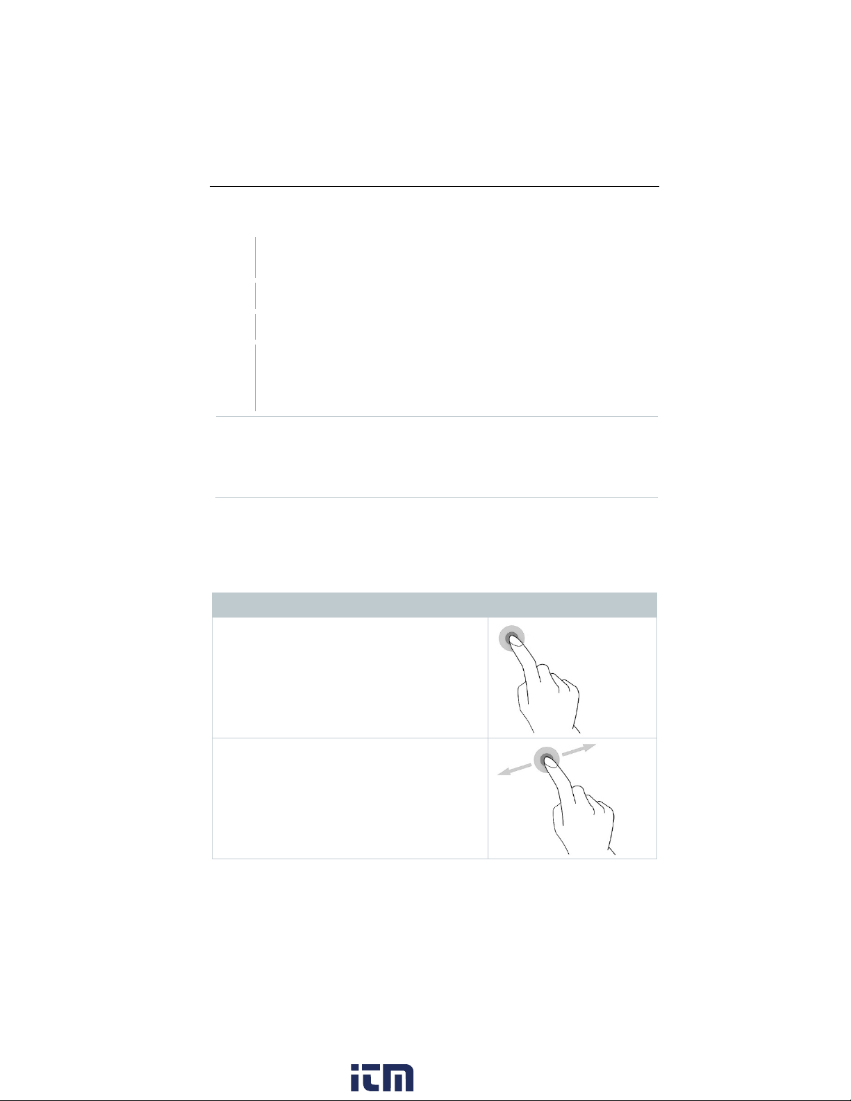
7.3
Tapping
Swiping
7 First steps
Power Supply (AC) operation
socket on the measuring instrument.
The measuring instrument is powered via the power supply.
If the instrument is turned off and a power plug is inserted, the
charging process will start automatically. Switching the measuring
instrument on stops the charging of the battery and the measuring
instrument is powered via the power supply.
For longer measurements involving AC operation, Testo recommends
using a combustion air temperature probe with connection cable. Selfheating of the instrument during AC operation may influence the
combustion air temperature measurement using a mini ambient air
probe.
Touchscreen operating concept
Familiarize yourself with the touchscreen operating concept before you use the
measuring instrument.
Actions are mostly performed by:
Description
To open applications, select menu symbols,
press buttons on the display or enter characters
with the keypad, in each case tap these with a
finger.
Swipe to the right or left on the display to show
further views, e.g. to switch from the list view to
the graphic view.
14
www. .com
information@itm.com1.800.561.8187

7 First steps
Zooming
7.4
1
Enter value: tap the required value
2
Confirm entry: Press .
3
Description
To make a section of the display larger or
smaller, touch the display with two fingers and
move them apart or together.
Dragging
You can move an element by touching it,
holding it and dragging it to the required
position.
Example: Changing the display sequence of the
measurement parameters.
Keypad
Some functions require values (figures, numerical value, unit, characters) to be
entered. The values are entered via a keypad.
Input field is enabled (flashing cursor)
on the display (figures, numerical
value, unit, characters).
Repeat steps as required.
15
www. .com
information@itm.com1.800.561.8187

7 First steps
7.5
Instrument
Press the button for
Instrument is turned on.
The tutorial demonstrates the general operation and the most important
button is pressed again.
Instrument
Press the button for
Selection: [OK] Instrument is turned off
with [Cancel].
Unsaved readings are lost when the measuring instrument is turned off.
Switch instrument on and off
Current
status
off
Instrument
on
on
Action Function
a long time (> 3 s)
When the measuring instrument is started for the first time, the setup
wizard guides you through the following setting parameters step by
step:
- Country version (basis of calculations)
- Language
- Wi-Fi
- Date and Time
- Own company address
- E-mail account*
- Product registration
A tutorial can be started after the setup wizard.
functions of the measuring instrument using examples.
Press the button
briefly (< 1 s)
a long time (> 1 s)
Instrument is turned to standby mode.
The instrument is re-activated when the
or cancel the instrument being turned off
*Note: If you don’t have your Email server information available you can skip
this step.
16
www. .com
information@itm.com1.800.561.8187

7.6
Instrument is turned on.
1
There must be no more than one extension line (0554 1201) between
Instrument is turned on.
1
Insert the connector plug of the
Connect probes
Flue gas probes
Insert the connector plug into the flue
gas socket and lock it in place by
turning it slightly clockwise (bayonet
lock).
measuring instrument and flue gas probe.
Temperature adapter
7 First steps
probe into the probe socket.
System recognizes the probe (info is displayed).
When an external “ext.” probe is used, the display will show “ext.”.
17
www. .com
information@itm.com1.800.561.8187

8
8.1
1 Measurement types
2
3 Main menu
4
Fuels
5 Select Customer/Measuring site
Select reading display type:
•
•
•
7
Stop measurement
8 Using the product
Using the product
User interface
Status bar
18
6
8
9
Open
List
Graphics
Hot Spot
Edit measurement data
Start measurement
Pause measurement
Options
selection list
www. .com
information@itm.com1.800.561.8187

Further symbols on the user interface (without numbering)
One level back
One level back
8.1.1
Refresh measurement
One level back
Cancel process
Print values
Save report
8 Using the product
Main measurement display - List
The measurement units and the number and order of the measurement
parameters displayed in the Main measurement display – List, can be changed,
Save and send report
see section Configure measurement display.
Only those parameters shown in the reading display appear in the saved
measurement and on the report printouts.
The settings only apply to the measurement type currently enabled.
www. .com
19
information@itm.com1.800.561.8187

8.1.2
1
Call up function: Graphics
2
Tap on to open selection list for measurement parameters/units.
3
Select desired measurement data / units.
8 Using the product
Main measurement display - Graphics
In the Main measurement display - Graphics, the reading progression can be
displayed as a line diagram.
A maximum of 4 measurement parameters can be set at any one time. Only
those measurement parameters can be displayed that are available in the Main
measurement display - Graphics.
The measurement parameters can be adjusted if necessary:
Measurement view is enabled.
20
Selection is accepted automatically.
www. .com
information@itm.com1.800.561.8187

8.1.3
1
Call up function: Hot Spot
2
3
Perform zeroing.
4
Align the flue gas probe in the flue so
8 Using the product
Main measurement display - Hot Spot
Search for hot spot:
Measurement view is enabled.
Start search:
The measurement starts automatically after zeroing.
that the probe tip is in the hot spot
(area of the highest flue gas
temperature Max Tstack).
- Grey value/grey pointer: Display
of current flue gas temperature
- Orange value/orange pointer:
Display of maximum flue gas
temperature
- Reset values/pointer:
21
www. .com
information@itm.com1.800.561.8187

8.2
Create, edit and delete customer and system
information.
possible).
Saved reports
Call up and delete measurement report.
Gas path check
For flawless operation of the measuring
recommended.
Device Settings
Settings
- Alarm limits
Sensor Diagnosis
Overview of the sensors installed and their
condition.
Error List
Show error reports
8 Using the product
Overview of main menu ( )
Main menu Description
Customer / Measuring site
Tests Call up, delete and send measurements that
have been performed (various formats
instrument, regular tightness testing of
measurement systems (measuring
instrument + flue gas probe) is
- Country version and language
- Wi-Fi
- Date & Time
- My company address
- Bluetooth®
- Hotspot
- Display brightness
- CO sensor protect
- NO2 addition
- O2 reference
22
www. .com
information@itm.com1.800.561.8187

Main menu Description
Device information
Information
Server information
Information about the available server
E-Mail
Set up e-mail account and the e-mail
account can be displayed.
My Apps
- File manager
Help
Aids
- Update via USB
8.2.1
1
- Device name
- Serial number
- Last service date
- Free memory
- Operating hours
- Operating hours since last service
- Software version
- Firmware version
- Firmware date
Additional applications
- Alarm clock
- E-Mail
- Gallery
- Browser
- Calendar
- Pocket calculator
- QuickSupport
8 Using the product
- Device Registration
- Tutorial
- Setup Wizard
- Help Online
- Testo Website
Customer / Measuring site (point)
Create, edit and copy Customer / Measuring site information.
Customer / Measuring site can be deleted.
Call up function: | Customer / Measuring site
Customer / Measuring site menu is displayed.
23
www. .com
information@itm.com1.800.561.8187

8 Using the product
View/edit existing data about
Customer / Measuring site
Create new Customer / Measuring
site
1
Tap Search operating field.
2
Enter search test using the text editor.
Via the search text, only the Customer / Measuring site is
3
1
Tap + New Customer / Measuring site.
2
Tap the required input field.
3
Enter the information via the keypad.
The following functions are available:
1 Search 3
2
Search
Text cursor flashes.
displayed that contains characteristics of the search text.
Confirm search result: press .
Create new customer
Customer input screen is opened.
Keypad appears.
24
www. .com
information@itm.com1.800.561.8187
 Loading...