


testo 330 -1, -2, -3 / testo 330 -1 , -2
, -2 Flue gas analyser
Instruction manual |
en |
|
|
|
|
|
|
2 General notes
General notes
Please read this documentation through carefully and familiarise yourself with the operation of the product before putting it to use. Keep this document to hand so that you can refer to it when necessary.
The document describes the country-specific version D of the testo 330-1, -2, -3 and testo 330-1 LL, -2 LL products.
Identification
Symbol |
Meaning |
Comments |
|
Warning advice: Warning! |
Read the warning advice carefully and take |
|
Serious physical injury could be caused if the |
the specified precautionary measures! |
|
specified precautionary measures are not taken. |
|
Warning advice: Caution!
Slight physical injury or damage to equipment could occur if the specified precautionary measures are not taken.
Read the warning advice carefully and take the specified precautionary measures!
|
Important. |
Please pay particular attention. |
|
|
|
(testo 330-1) |
The description applies only for the |
- |
|
instrument indicated: testo 330-1, -2, -3 / |
|
|
testo 330-1LL, -2LL. |
|
Text |
Text appears on the instrument’s display |
- |
|
Key |
Press the key. |
OK |
Function key with the function “OK”. |
Press function key. |
xyz |
Short form for operating steps. |
See short form, p. 3. |
General notes 3
Short form
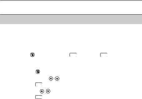
This document uses a short form for describing operating steps (e.g. calling up a function).
Example: Calling up the Flue gas function
Short form: |
Measurements |
OK |
Flue gas OK |
||
|
(1) |
(2) |
(3) |
(4) |
(5) |
Steps required: |
|
|
|
|
|
1 |
Open main menu: |
. |
|
|
|
2 |
Select Measurements menu: , . |
|
|
|
|
3 |
Confirm selection: |
OK . |
|
|
|
4 |
Select Flue gas menu: , . |
|
|
|
|
5 |
Confirm selection: |
OK . |
|
|
|

4 Contents
Contents
See also Functional overview, p. 63.
|
General notes |
........................................................................................ |
2 |
|
|
Contents ................................................................................................ |
|
4 |
|
A. |
Safety advice |
........................................................................................ |
7 |
|
B. |
Intended purpose .................................................................................. |
9 |
||
C. |
Product description ............................................................................ |
10 |
||
|
C.1 |
Measuring instrument .................................................................. |
10 |
|
|
|
C.1.1 |
Overview .................................................................................. |
10 |
|
|
C.1.2 |
Keypad .................................................................................... |
11 |
|
|
C.1.3 |
Display .................................................................................... |
11 |
|
|
C.1.4 |
Device connections .................................................................. |
12 |
|
|
C.1.5 |
Interfaces ................................................................................ |
13 |
|
|
C.1.6 |
Components ............................................................................ |
13 |
|
|
C.1.7 |
Carrying strap / barcode pen holder .......................................... |
14 |
|
C.2 |
Modular flue gas probe ................................................................ |
15 |
|
D. |
Commissioning .................................................................................... |
16 |
||
E. |
Operation ............................................................................................ |
|
17 |
|
|
E.1 |
Mains unit / rechargeable battery .................................................. |
17 |
|
|
|
E.1.1 |
Changing the battery .............................................................. |
17 |
|
|
E.1.2 |
Charging batteries .................................................................... |
18 |
|
|
E.1.3 |
Operation with the mains unit .................................................. |
18 |
|
E.2 |
Probes / Sensors .......................................................................... |
19 |
|
|
|
E.2.1 |
Connecting probes / sensors .................................................... |
19 |
|
|
E.2.2 |
Replacing the probe module .................................................... |
20 |
|
E.3 |
Regular care ................................................................................ |
20 |
|
E.3.1 |
Condensate trap ...................................................................... |
20 |
E.3.2 |
Checking / replacing the particle filter ........................................ |
21 |

Contents 5
|
E.4 |
Basic operating steps .................................................................. |
21 |
|
|
|
E.4.1 |
Switching the measuring instrument on .................................... |
21 |
|
|
E.4.2 |
Calling up a function ................................................................ |
22 |
|
|
E.4.3 |
Entering values ........................................................................ |
22 |
|
|
E.4.4 |
Printing data ............................................................................ |
23 |
|
|
E.4.5 |
Saving data .............................................................................. |
23 |
|
|
E.4.6 |
Confirming an error message .................................................. |
23 |
|
|
E.4.7 |
Scanning locations with the barcode pen ................................ |
24 |
|
|
E.4.8 |
Switching the measuring instrument off .................................... |
24 |
|
E.5 |
Memory / Location ........................................................................ |
25 |
|
|
E.6 |
Instrument diagnosis .................................................................. |
27 |
|
F. |
Configuration |
...................................................................................... |
28 |
|
|
F.1 |
Instrument settings ...................................................................... |
28 |
|
|
|
F.1.1 |
Display edit .............................................................................. |
28 |
|
|
F.1.2 |
Printer ...................................................................................... |
29 |
|
|
F.1.3 |
Alarm limits .............................................................................. |
30 |
|
|
F.1.4 |
Start Keys edit ........................................................................ |
30 |
|
|
F.1.5 |
t315-3 Connect ........................................................................ |
31 |
|
|
F.1.6 |
Communication ........................................................................ |
32 |
|
|
F.1.7 |
Date / Time .............................................................................. |
32 |
|
|
F.1.8 |
Language ................................................................................ |
32 |
|
F.2 |
Sensor settings ............................................................................ |
33 |
|
|
F.3 |
Fuels .......................................................................................... |
|
34 |
G. |
Measuring ............................................................................................ |
|
35 |
|
|
G.1 |
Preparing measurements ............................................................ |
35 |
|
|
|
G.1.1 |
Zeroing phases ........................................................................ |
35 |
|
|
G.1.2 |
Using the modular flue gas probe ............................................ |
36 |
|
|
G.1.3 |
Configuring the reading display ................................................ |
36 |
|
|
G.1.4 |
Set memory/location ................................................................ |
36 |

6 Contents
|
G.2 |
Measurements ............................................................................ |
37 |
|
|
|
G.2.1 |
Flue gas .................................................................................. |
37 |
|
|
G.2.2 |
Draught .................................................................................... |
38 |
|
|
G.2.3 |
Fine pressure probe (accessory) .............................................. |
38 |
|
|
G.2.4 |
BImSchV (testo 330-3 / testo 330-2 LL) .................................. |
39 |
|
|
G.2.5 |
Solid fuel measurement (testo 330-2) ........................................ |
41 |
|
|
G.2.6 |
CO undiluted ............................................................................ |
42 |
|
|
G.2.7 |
Smoke No. / HCT .................................................................... |
42 |
|
|
G.2.8 |
Differential pressure .................................................................. |
43 |
|
|
G.2.9 |
Differential temperature ............................................................ |
44 |
|
|
G.2.10 |
O2 air ...................................................................................... |
44 |
|
|
G.2.11 |
Gas flow rate .......................................................................... |
45 |
|
|
G.2.12 |
Oil flow rate .............................................................................. |
45 |
|
|
G.2.13 |
Leak detection ........................................................................ |
46 |
|
|
G.2.14 |
Ambient CO ............................................................................ |
46 |
|
|
G.2.15 |
Ambient CO2 .......................................................................... |
47 |
|
|
G.2.16 |
Burner control .......................................................................... |
48 |
I. |
Transfering data .................................................................................. |
50 |
||
|
H.1 |
Protocol printer ............................................................................ |
50 |
|
|
H.2 |
PC / Pocket PC ............................................................................ |
50 |
|
I. |
Care and maintenance ........................................................................ |
51 |
||
|
I.1 |
Cleaning the measuring instrument .............................................. |
51 |
|
|
I.2 |
Replacing measuring cells .......................................................... |
51 |
|
|
I.3 |
Recalibrating measuring cells ...................................................... |
52 |
|
|
I.4 |
Replacing additional filter ............................................................ |
52 |
|
|
I.5 |
Cleaning the modular flue gas probe ............................................ |
53 |
|
|
I.6 |
Changing the thermocouple ........................................................ |
53 |
|
J. |
Questions and Answers ...................................................................... |
54 |
||
K. |
Technical data .................................................................................... |
55 |
||
|
K.1 |
Standards and inspections .......................................................... |
55 |
|
|
K.2 |
Measuring ranges and accuracies .............................................. |
56 |
|
|
K.3 |
Other device data ........................................................................ |
57 |
|
|
K.4 |
EC declaration of conformity ........................................................ |
58 |
|
|
K.5 |
Principles of calculation .............................................................. |
59 |
|
|
|
K.5.1 |
Fuel parameters ...................................................................... |
59 |
|
|
K.5.2 |
Calculation formulae ................................................................ |
59 |
L. Accessories/Spare parts |
....................................................................61 |
Functional overview ............................................................................ |
63 |
A. Safety advice 7
A. Safety advice
 Avoid electrical hazards:
Never use the measuring instrument and probes to measure on or near live parts!
 Protect the measuring instrument:
Never store the instrument / measuring cells together with solvents (e.g. acetone). Do not use any dessicants.
 Product with Bluetooth® (Option)
Changes or modifications, which are not expressly approved by the responsible official body, can lead to a withdrawal of operating permission.
Interference with data transfer can be caused by instruments which transmit on the same ISM band, e.g. microwave ovens, ZigBee.
The use of radio connections is not allowed in e.g. aeroplanes and hospitals. For this reason, the following point must be checked before entering:
Deactivate Bluetooth function:
 Inst’ settings OK Communication OK IrDA OK .
 Product safety / preserving warranty claims:
Operate the measuring instrument only within the parameters specified in the technical data.
Handle the instrument properly and according to its intended purpose.
Never apply force!
Temperatures given on probes / sensors relate only to the measuring range of the sensors. Do not expose handles and feeders to any temperatures in excess of 70 °C unless they are expressly permitted for higher temperatures.
Open the measuring instrument only when this is expressly described in the Operating Instructions for maintenance purposes.
Carry out only the maintenance and repair work that is described in the Operating Instructions. Follow the prescribed steps exactly. For safety reasons, use only original spare parts from Testo.
The testo 330 must be checked before commissioning for any visible damage. Do not commission the testo 330 if there are signs of damage on the housing, mains unit or supply lines. Electrical risk..
8 A. Safety advice
Any further or additional work must only be carried out by authorised personnel. Testo will otherwise refuse to accept responsibility for the proper functioning of the measuring instrument after repair and for the validity of certifications.

 Ensure correct disposal:
Dispose of defective rechargeable batteries and spent batteries at the provided collection points.
Send the measuring instrument directly to us at the end of its life cycle. We will ensure that it is disposed of in an environmentally friendly manner.

B. Intended purpose 9
B. Intended purpose
This chapter describes the areas of application for which the measuring instrument is intended.
The testo 330 is a handheld measuring device for the professional flue gas analysis of furnace systems:
·Small furnaces (burning oil, gas, wood, coal)
·Low-temperature and condensing boilers
·Gas heaters
These systems can be adjusted using the testo 330 and checked for compliance with the applicable limit values.
The measuring instrument is approved for measurements under the German regulations on immissions protection (1. BImSchV).
The following tasks can also be carried out with the testo 330:
·Regulating the O2-, COand CO2-, NO-, NOx values in furnaces for the purpose of ensuring optimal operation.
·Draught measurement.
·Measuring and regulating the gas flow pressure in gas heaters.
·Measuring and optimising the flow and return temperatures of heating systems.
·COand CO2 environment measurement.
·Detection of CH4 (methane) and C3H8 (propane).
testo 330 should not be used:
·for continuous measurements
·as a safety (alarm) instrument
The testo 330 with the Bluetooth option may only be operated in countries in which it is type approved (see Technical Data).
10C. Product description C.1 Measuring instrument
C. Product description
This chapter provides an overview of the individual components of the product.
C.1 Measuring instrument
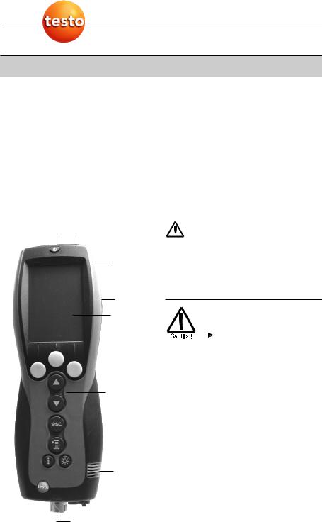
C.1.1 Overview
Placeholder:
Uebersicht.tif
Switch on / off
Interfaces: USB, PS2, infrared Do not direct infrared beam at  human eyes.
|
Condensate trap (on rear) |
|
|
Fixing eyelets for carrying strap (left and |
|
right) |
||
|
||
|
Display |
|
|
Magnetic holders (on rear) |
|
|
|
Strong magnets |
||
|
|
Damage to other magnets |
|||
|
|
|
|
||
|
|
|
Keep safe distance from |
||
|
|
||||
|
|
|
|
products which could be |
|
|
|
|
|
damaged by magnets (e.g. |
|
|
|
|
|
monitors, computers, |
|
|
|
|
|
pacemakers, credit cards). |
|
|
|
|
|||
Keypad |
|||||
|
|
|
|
||
|
|
|
|
Service cover (on rear) |
|
|
|
|
Gas outlet |
||
|
|
|
|
||
|
|
|
|
Unit connections: flue gas probe, |
|
|
|
|
|
probe, pressure probe, mains unit |
|

C. Product description 11
C.1 Measuring instrument
C.1.2 Keypad
Key Functions
Switch measuring instrument on/off
Function key (orange, 3x), relevant function is shown on the display
Scroll up, increase value
Scroll down, reduce value
Back, cancel function
Open Main menu: press briefly (changed settigs are stored, measurement values are carried over into the menu Flue gas); open Measurements menu: press and hold down for 2s (changed settigs are stored, measurement
values are carried over into the menu Flue gas)
Open Inst’ diagnosis menu
Switch over display light: display light is permanently on or display light goes on for 10 seconds everytime a key is activated.
C.1.3 Display
Depending on the menu that is active, the display shows a variety of elements.
Header (active in all views)
Warning symbol (only if there is a device error; the
device error is displayed in the Inst’ diagnosis menu).
Active location.
Power supply symbol:
Symbol |
Characteristic |
Symbol |
Characteristic |
||||
|
|
|
Mains operation |
|
|
|
Rech. battery operation, capacity: 26-50% |
|
|
|
|
|
|
||
|
|
|
|
|
|
|
|
|
|
|
Rech. battery operation, capacity: 76-100% |
|
|
|
Rech. battery operation, capacity: 6-25% |
|
|
|
Rech. battery operation, capacity: 51-75% |
|
|
|
Rech. battery operation, capacity: 0-5% |
Function select view
Active menu, activated fuel
Selection field for functions:
The chosen function is shown with a grey background.
Unavailable functions are written in grey type.
Scroll bar
Function keys for entering commands

12C. Product description C.1 Measuring instrument
Settings view
Active menu
Function fields for entering commandsScroll bar
Selection field for adjustable values: The chosen value is shown with a grey
background. Unavailable values are written in grey type.
Function keys for entering commands
Active menu, depending on the chosen function: Additional information (e.g. activated fuel,
date and time)
Scroll bar
Display field for readings, parametersFunction keys for entering commands
C.1.4 Device connections
Probe socketFlue gas socket
Mains unit socketPressure socket
C. Product description 13
C.1 Measuring instrument
C.1.5 Interfaces
|
|
USB interface: |
|||||
|
|
|
|
|
|
|
connection to PC |
|
|
|
|
|
|
|
|
|
|
|
|
|
|
|
PS2 interface: |
|
|
|
|
|
|
|
|
|
|
|
|
|
|
|
connection to barcode pen, adapter for automatic |
|
|
|
|
|
|
|
furnaces |
|
|
|
|
|
|
|
|
|
|
|
|
|
|
|
Infrared interface (IrDA): connection to Ir/IrDA |
|
|
|
|
|
|
|
printers / Pocket PC |
|
|
|
|
|
|
|
Bluetooth interface (option): connection to |
|
|
|
|
|
|
|
Bluetooth printers / Pocket PC |
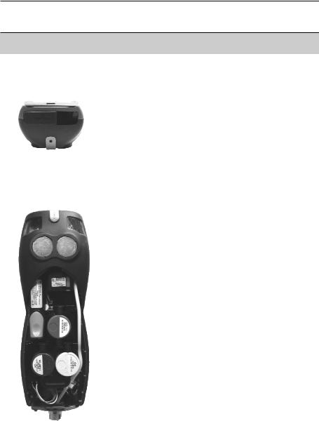
C.1.6 Components
Rechargeable batteryMeasuring gas pump
Slot for CO measuring cellSlot for O2 measuring cell
Slot for NO-, NO low measuring cellAdditional filter
|
|
|
|
|
|
|
|
|
|
|
||
|
|
|
|
|
|
|
|
|||||
|
|
|
|
|
|
|
|
|
||||
|
|
|
|
|
|
|
||||||
|
|
|
|
|
|
|
|
|
|
|||
|
|
|
|
|
|
|
|
|||||
|
|
|
|
|
|
|
|
|
|
|
||
|
|
|
|
|
|
|
|
|
|
|||
|
|
|
|
|
|
|
|
|
|
|
|
|
|
|
|
|
|
|
|
|
|
|
|
|
|
14C. Product description C.1 Measuring instrument
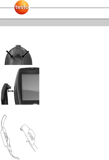
C.1.7 Carrying strap/barcode pen holder
To secure the carrying strap:
1Remove sealing caps from the sides of the housing.
Fix sealing caps on the inside of the service cover: 1 Place the measuring instrument on its front.
2 Pick the service cover up at the markings (arrows) using your index finger and thumb and press gently to release the lock.
3 Fold the service cover up and remove it.
4Secure the sealing caps in the two holders on the inside of the service cover ( ).
5 Attach the service cover and engage it in place.
2Engage the carrying strap clip in the fixing eyelets on the side of the device. Note the guide groove. The strap must point “down” ( ).
To secure the barcode pen holder to the carrying strap:
1Loosen the carrying strap at the buckle and remove.
2 Lead carrying strap through the strap guide of the barcode pen holder ( ).
3Lead carrying strap through the buckle ( ) and tighten.

C. Product description |
15 |
C.2 Modular flue gas probe |
|
C.2 Modular flue gas probe
|
|
|
|
|
|
Removable filter chamber with window and particle |
||||||
|
|
|
||||||||||
|
|
|
|
|
|
|
|
|
|
|
|
filter |
|
|
|
|
|
|
|
|
|
|
|
||
|
|
|
|
|
|
|
|
|
|
|
|
Probe handle |
|
|
|
|
|
|
|
|
|
|
Connecting cable |
||
|
|
|
|
|
|
|
|
|
|
|||
|
|
|
|
|
|
|
|
|
|
|
|
|
|
|
|
|
|
|
|
|
|
|
|
|
Connecting plug for measuring instrument |
|
|
|
|
|
|
|||||||
|
|
|
|
|
|
|
|
|
|
|
|
Probe module lock release |
|
|
|
|
|
|
|
|
|
|
|
|
Probe module |
16 D. Commissioning
D. Commissioning
This chapter describes the steps required to commission the product.
Remove the protective film from the display.
The measuring instrument is supplied with a rechargeable battery already fitted.
Charge the battery up fully before using the instrument (see Charging batteries, p. 18).
E. Operation 17
E.1 Mains unit / rechargeable battery
E. Operation
This chapter describes the steps that have to be executed frequently when using the product.
Please read this chapter carefully. The following chapters of this document will assume you are already familiar with the content of this chapter.
E.1 Mains unit/rechargeable battery
If the mains unit is connected, the measuring instrument is automatically powered from the unit. It is not possible to charge the battery in the instrument during operation.
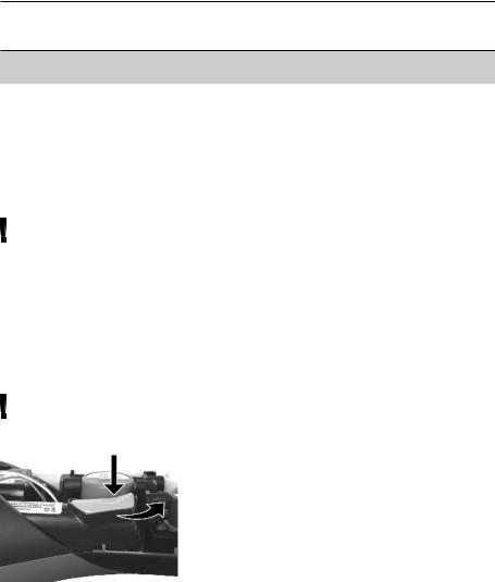
E.1.1 Changing the battery
The measuring instrument must not be connected to a mains socket via the mains unit. The instrument must be switched off. Change the rechargeable battery within 60 minutes so that device settings (e.g. date / time) are not lost.
1 Place the measuring instrument on its front.
2Remove the service cover: Take hold of it at the markings (arrows) using the index finger and thumb, press slightly, fold up and remove.
3Open the battery lock: Press the orange key and push in the direction of the arrow.
4Remove the battery and insert a new rechargeable battery. Only use the Testo rechargeable battery 0515 0100.
5Close battery lock: Press the orange key and push against the direction of the arrow until the battery engages.
6 Attach the service cover and engage it in place.
18E. Operation
E.1 Mains unit / rechargeable battery
E.1.2 Charging batteries
The rechargeable battery can only be charged at an ambient temperature of ±0 to +35 °C. If the battery has discharged completely, the charging time at room temperature is approximately 5-6 h.
Charging in the measuring instrument
The instrument must be switched off.
1Connect the plug of the mains unit to the mains unit socket on the measuring instrument.
2 Connect the mains plug of the mains unit to a mains socket.
-The charging process will start. The charge condition will be shown on the display. The charging process will stop automatically when the battery is fully charged.
Recharging in the charging station (0554 1087)
Refer to the documentation enclosed with the charging station.
Battery care
If possible, always discharge the battery and recharge it fully.
Do not store the battery for long periods when discharged. (The best storage conditions are at 50-80% charge level and 10-20 °C ambient temperature; charge fully before further use).
E.1.3 Operation with the mains unit
1Connect the plug of the mains unit to the mains unit socket on the measuring instrument.
2 Connect the mains plug of the mains unit to a mains socket.
-The measuring instrument is powered via the mains unit.
-If the instrument is switched off and a rechargeable battery is inserted, the charging process will start automatically. Switching the instrument on has the effect of stopping battery charging and the instrument is then powered via the mains unit.
E. Operation 19
E.2 Probes / Sensors
E.2 Probes/Sensors
E.2.1 Connecting probes/sensors
Probe socket:
Probe detection is carried out at the socket during the initial switch on activation process: Probes that are required must always be connected before the measuring instrument is switched on, or the instrument must be switched off and then on again after a change of probe, so that the correct data can be read into the instrument.
Flue gas socket:
Probe / sensor detection at the flue gas socket is carried out continuously. It is possible to change the probe / sensor even while the measuring instrument is switched on.
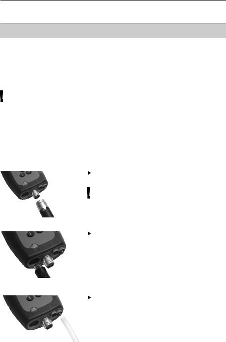
Connect flue gas probes/gas pressure adapters/temperature adapters
Insert the connector into the flue gas socket and lock by turning it clockwise gently (bayonet lock).
Only one hose extension (0554 1201) should be connected between the measuring instrument and the flue gas probe.
Connecting other probes
Insert the connector of the probe into the probe socket.
Connecting the pressure hose
Fit the pressure hose on the connecting nipple of the pressure socket.
20E. Operation E.3 Regular care
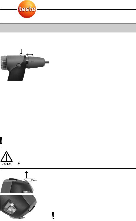
E.2.2 Replacing the probe module
1Press the key on the top of the probe handle and remove the probe module.
2 Fit a new probe module and engage it in place.
E.3 Regular care
E.3.1 Condensate trap
The fill level of the condensate trap can be read from the markings on the trap.
A warning message ( red flashing light) is displayed if the level in the condensate trap reaches 90%.
Emptying the condensate trap
The condensate consists of a weak mix of acids. Avoid contact with the skin. Make sure that the condensate does not run over the housing.
Condensate in gas path.
Damage to measuring cells and flue gas pump.
Do not empty condensate trap while pump is operating.
1Hold the measuring instrument so that the
condensate outlet points up.
2Open condensate outlet in condensate trap: Pull out approx. 5mm or until it will not go any further ( ).
3 Let the condensate run out into a sink ( ).
4 Dab off drops at condensate outlet using a cloth. 5 Close the condensate outlet.
The condensate outlet must be fully closed (marking) otherwise incorrect measurements due to
E. Operation 21
E.4 Basic operating steps
inleaking air may result.
E.3.2 Checking/replacing the particle filter
Checking the particle filter:
Particle filters of the modular flue gas probe must be checked regularly for contamination:
Check visually by looking through the window of the filter chamber.
Replace the filter if there are signs of contamination.
Replacing the particle filter:
Filter chamber may contain condensate.
1Open the filter chamber: Turn gently anticlockwise.
2Remove the filter plate and replace it with a new one (0554 3385).
3Fit the filter chamber and lock it: Turn gently clockwise.
E.4 Basic operating steps
E.4.1 Switching the measuring instrument on
 .
.
-The start screen is displayed (for about 5 s).
-Display illumination is switched on for 10 s. Option:
 To go directly to a measurement while the start screen is being displayed, press the function key for the desired measurement. See also Start key configuration, p. 30.
- The Measurements menu is opened. -or-
-If another probe / sensor is connected rather than a flue gas probe: the measuring menu for that probe / sensor is opened.
 Loading...