

Page 1
testo 240
Leitfähigkeits-Meßgerät
Bedienungsanleitung de
Instruction manual en
Page 2

Inhalt
Gerätebeschreibung
Benutzungshinweise
Sicherheitshinweise
Inbetriebnahme
Fühlermontage ............................................................................6
Gerät einschalten.........................................................................7
Auto Off Funktion ........................................................................7
Zellenkonstante speichern ...........................................................8
Temperaturkoeffizient einstellen...................................................9
Leitfähigkeits MMessung
HOLD-Funktion .........................................................................10
Zel
lenkonstante eermitteln
Konfiguration
°C/°F Umschaltung • Auto-Off Funktion ein-/ausschalten..........12
Pflege uund WWartung
Allgemeine Hinweise..................................................................13
Batteriewechsel.........................................................................14
Fehlermeldungen
ERROR 1-3 ...............................................................................15
ERROR 4+7 ..............................................................................16
Technische DDaten
Gerät.........................................................................................17
Leitfähigkeits-Meßzellen.............................................................18
Temperaturfühler .......................................................................18
Garantie ....................................................................................18
.............................................................................3
.............................................................................5
..............................................................................5
.....................................................................................6
......................................................................10
...................................................................11
......................................................................................12
............................................................................13
................................................................................15
...............................................................................17
Bestelld
Anhang
aten
........................................................................................19
................................................................................................19
Funktionsprinzip der Leitfähigkeitsmeßzelle................................20
Temperaturkoeffizienten ausgewählter Lösungen ......................21
Grundsätzliches zur linearen Temperaturkompensation .............22
Meßgerät kkonform zzu
EN 550 0081-11 ++ EEN 550 0082-11
2
Page 3
testo
term
mS/cm mS/cm
¡C / ¡F
testo
®
240
SELECT
HOLD
I
0
Bat
Hold
¡
k
¡
W
Auto
m
mS/cm
p
m
V
2
pH
Man
/
x
NaCl
X
%/
D
IN
/N
B
S
mg/l
Cal
testo
term
Tastatur
Display
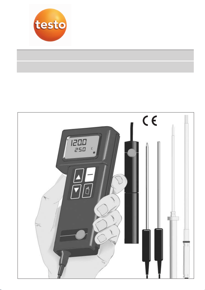
Gerätebeschreibung
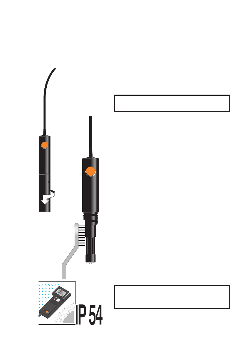
Leitfähigkeits-Meßzelle
Batteriefach
Anschlußbuchse
Leitfähigkeits-Meßzelle
Temperatur-Fühler
Dichtringe
MeßElektroden
TemperaturSensor
Entlüftungslöcher
Temperatur-Fühler
Hüllrohr
3
Page 4
mmS/cm
NaCl mg/l
Gerätebeschreibung
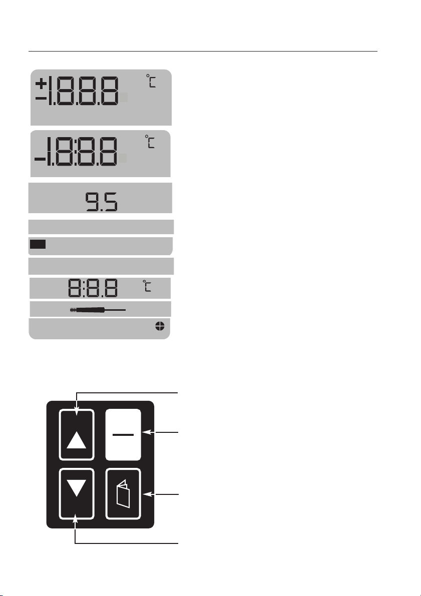
Display //Tastatur
1.Zeile
Darstellung des Meßwertes (µS/cm, mS/cm,
NaCl mg/l - °C/°F bei Messung mit Temperaturfühler) und der Menüebene.
2. Zeile
Darstellung des Temperaturwertes.
Bat
Hold
Cal
HOLD
%/
I
0
Batteriekontrolle
Beim Einschalten: Batteriespannung
Im Betrieb: Warnung schwache Batterie
"HOLD"
Kalibrier-Menü aktiv
k
Kalibriermenü
Temperaturkoeffizient
Messung mit Temperaturfühler
Auto-Off Funktion
HOLD-
manueller Eingabefunktion Werte einstellen)
EIN/AUS
-Funktion aktiv.
"Zellenkonstante"
Taste (Meßwerte festhalten oder bei
-Taste
4
SELECT
BLÄTTER
(einzelne Menüebenen aufrufen)
SELECT
manueller Eingabefunktion Werte einstellen)
-Taste
-Taste (Menüpunkte auswählen oder bei
Page 5
Benutzungshinweise
testo
term
m
S
/
c
m
m
S
/
c
m
¡
C
¡F
te
st
o
®
24
0
H
O
L
D
I
0
240
testo
dient zum Ermitteln der Leitfähigkeit , des Salzgehaltes und der Temperatur in wässrigen
Lösungen.
Bat
Hold
X
m
Cal
V
/
m
¡
p
m
p
DIN/NB
S
H
2
/c
NaCl
m
S
%/
mg/l
x
¡
M
a
k
A
n
u
W
t
o
240
testo
ist ein pflegeleichtes, robustes und einfach zu
bedienendes Leitfähigkeits- und Temperatur-meßgerät mit einem Meßbereich
von 0 bis 2000mS/cm, 1 bis 200 mg/l NaCl
sowie -50 bis +150 ° C.
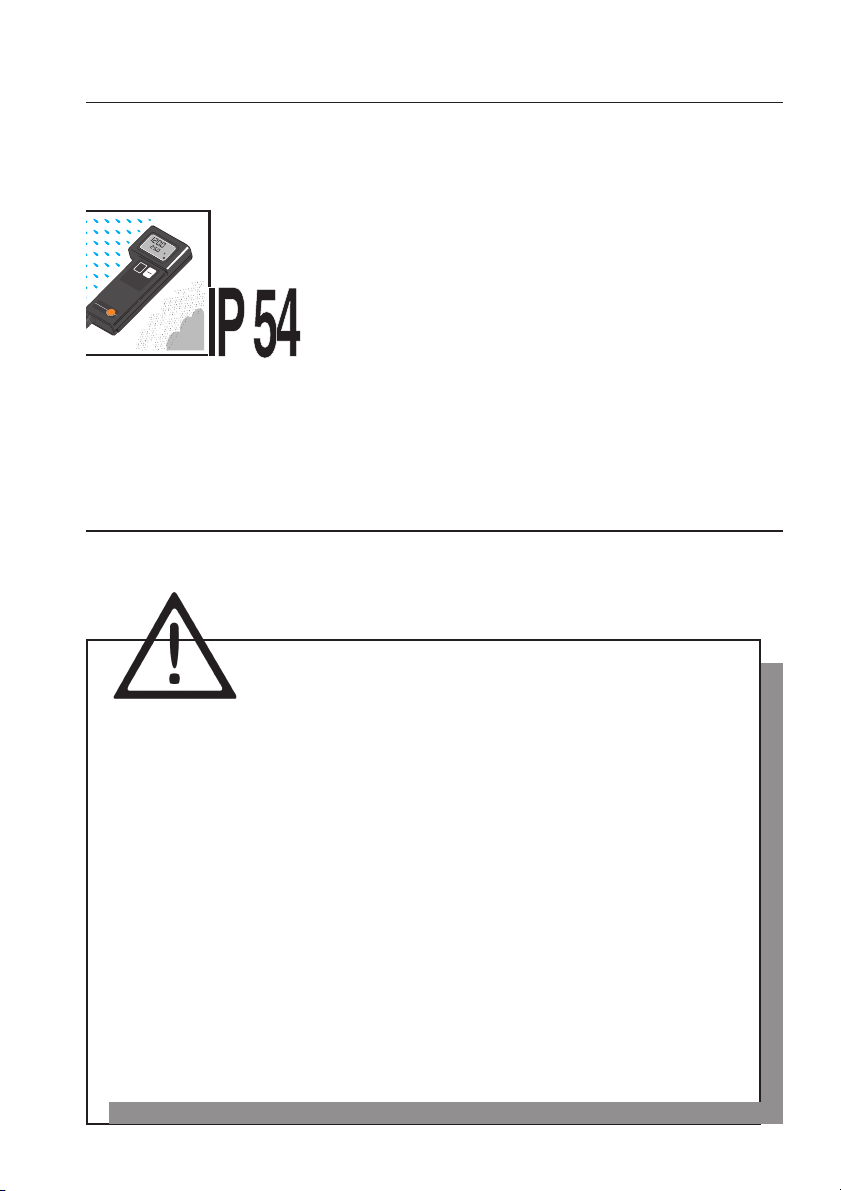
Das wasserdichte Gehäuse (Schutzart IP 54,
Schutz gegen Spritzwasser und Staubablagerungen), die einfache Einhandbedienung, die verschiedenen Leitfähigkeits-Meßzellen und Temperatur-
Sicherheitshinweise
Fühler erlauben einen vielseitigen Einsatz.
Bitte uunbedingt
vor IInbetriebnahme llesen!
Nicht an spannungsführenden Teilen messen!
Das hier beschriebene Gerät ist für den Einsatz
im medizinischen Bereich nicht geeignet!
Zulässige Lager- und Transporttemperatur sowie die zul. Betriebstemperatur
beachten (z.B. Meßgerät vor direkter Sonneneinstrahlung schützen!
Schutzart IP 54 ist nur bei eingestecktem Fühler gegeben!
Bei Öffnen oder unsachgemäßer Behandlung oder Gewaltanwendung
erlöschen die Gewährleistungsansprüche!
5
Page 6
Inbetriebnahme
te
s
to
te
r
m
mS/cm mS/cm
¡C / ¡F
testo
®
240
S
E
L
E
C
T
H
O
L
D
I
0
B
a
t
H
o
ld
¡
k
¡
W
Auto
m
mS/cm
p
m
V
2
pH
M
an
/
x
N
a
C
l
X
%/
D
I
N
/N
B
S
m
g
/l
C
a
l
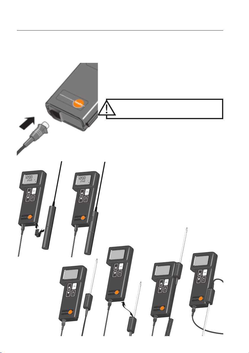
Fühlermontage
Vor dem Einschalten, den Stecker der Leitfähigkeits-Meßzelle in die Buchse des Gerätes stecken.
Achten Sie auf die Markierungen (><) an Stecker
und Gerät.
Beim Entfernen des Steckers nicht
an der Leitung ziehen!
Die Meßzelle sowie die Temperaturfühler
können lose oder aufgesteckt verwendet werden.
¡
2
p
/
V
m
S/cm
m
m
S
B
N
/
N
I
x
D
/l
g
m
l
C
a
N
t
a
B
¡
k
%/
ld
o
H
W
an
M
X
Auto
pH
l
a
C
D
L
O
I
H
0
T
C
E
L
E
S
®
to
s
240
te
testo
m
r
te
mS/cm mS/cm
¡C / ¡F
¡
2
p
/
V
m
mmS/cm
S
B
N
/
N
I
x
D
/l
g
m
l
C
a
N
t
a
B
¡
k
%/
ld
o
H
W
Man
X
Auto
pH
l
a
C
D
L
O
I
H
te
mS/cm mS/cm
0
T
C
E
L
E
S
®
40
to
s
2
te
sto
m
r
te
¡C / ¡F
¡
2
p
/
V
te
mS/cm mS/cm
m
mmS/cm
S
B
N
/
N
I
x
D
/l
g
m
l
C
a
N
t
a
B
¡
k
%/
ld
o
H
W
Man
X
Auto
pH
l
a
C
D
L
O
I
H
0
T
C
E
L
E
S
®
40
to
s
2
te
sto
m
r
te
¡C / ¡F
te
mS/cm mS/cm
¡
2
p
/
V
m
S/cm
mm
S
B
N
/
N
I
x
D
/l
g
m
l
C
a
N
t
a
B
¡
k
%/
ld
o
H
W
Man
X
Auto
pH
l
a
C
D
L
O
I
H
0
T
C
E
L
E
S
®
40
to
s
2
te
sto
m
r
te
¡C / ¡F
te
mS/cm mS/cm
¡
2
p
/
V
m
mmS/cm
S
B
N
/
N
I
x
D
/l
g
m
l
C
a
N
t
a
B
¡
k
%/
ld
o
H
W
Man
X
Auto
pH
l
a
C
D
L
O
I
H
0
T
C
E
L
E
S
®
40
to
s
2
te
sto
m
r
te
¡C / ¡F
6
Page 7
Inbetriebnahme
Gerät eeinschalten
Bat
Hold
Cal
Bat
Hold
Cal
¡
2
p
/
V
m
mmS/cm
x
DIN/NBS
mg/l
NaCl
Bat
¡
k
%/
Hold
W
Man
X
Auto
pH
Cal
I
HOLD
0
T
C
E
L
E
S
®
240
testo
testo
term
/cm
S
m
/cm
mS
/ ¡F
¡C
I
0
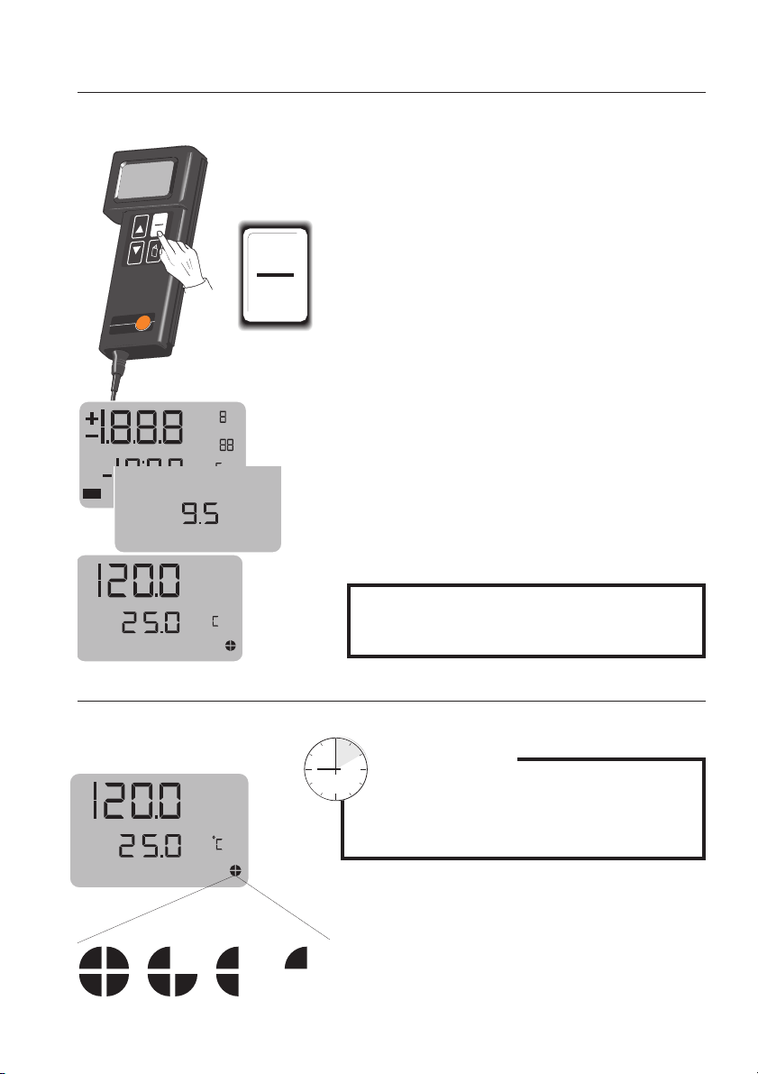
Gerät einschalten.
Nach dem Einschalten erfolgt ein kurzer Anzeigen-
¡
/
p
mV
2
mmS/cm
DIN/NBS
x
NaCl
mg/l
¡
%/
X
pH
Bat
Man
Auto
k
W
und Funktionstest, gefolgt von einer
Batteriekontrolle welche Ihnen beim Einschalten
die Batteriespannung anzeigt (s. auch
Batteriewechsel).
Das Meßgerät ist jetzt einsatzbereit.
¡
/
p
mV
2
mS/cm
m
DIN/NBS
x
NaCl
mg/l
¡
%/
X
pH
Man
Auto
k
W
Vor der ersten Messung muß die
Zellenkonstante im Gerät gespeichert werden!
ACHTUNG!
Die Auto-Off-Funktion wird im Display angezeigt.
Im 2,5 Minuten Rhytmus erlöschen die Kreisseg-
mS/cm
n
Auto-OOff-FFunktion
mente im Display.
Auto-OOff-FFunktion
Wird das Meßgerät 10
Min. lang nicht bedient erfolgt eine automatische
Abschaltung
W
Nach dem letzten Segment schaltet das Gerät ab.
7
Page 8
k
Cal
te
mS/cm mS/cm
Inbetriebnahme
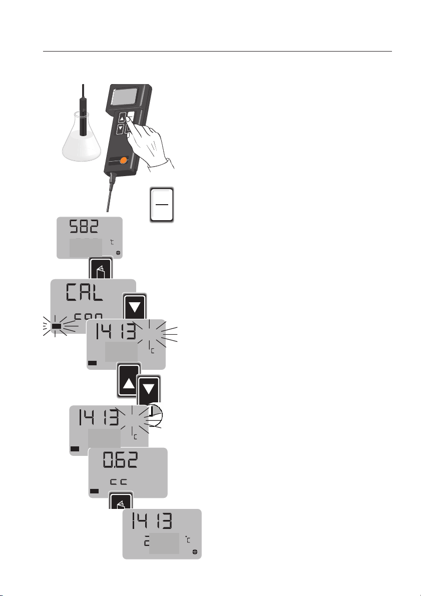
Zellenkonstante sspeichern
¡
2
p
/
V
m
S/cm
mm
S
B
N
/
N
I
x
D
/l
g
m
l
C
a
N
t
a
B
¡
k
%/
ld
o
H
W
an
M
X
Auto
pH
l
a
C
D
L
O
I
H
0
T
C
E
L
E
S
®
0
to
s
24
te
sto
m
r
te
¡C / ¡F
I
0
Aus fertigungstechnischen Gründen variiert die Zellenkonstante der Leitfähigkeitsmeßzellen.
Vor dder eersten MMessung
muß darum die auf dem
Kabel angegebene Zellenkonstante der
verwendeten Meßzelle im Gerät gespeichert
werden.
Kabelverbindung zwischen Meßzelle und Gerät
herstellen.
m S/cm
x
NaCl mg/l
W
Cal
pH
Man
Auto
%/
Cal
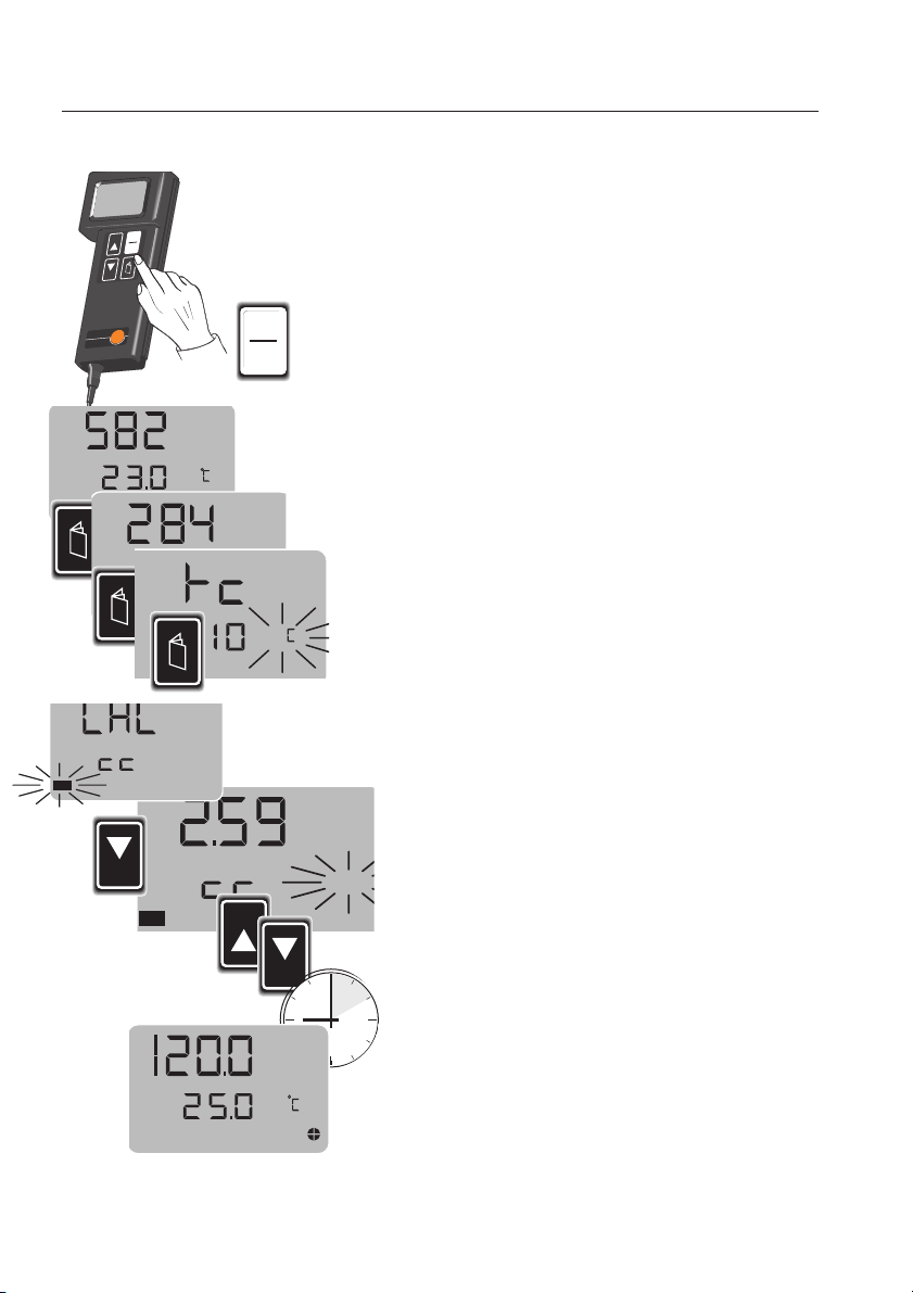
Gerät einschalten.
Nach dem Anzeigen und Funktionstest mit der
BLÄTTER
Mit
ein Wert und
-Taste in das
SELECT
"CAL"
-Menü wechseln.
bestätigen, im Display erscheint jetzt
"k"
(Konstante) blinkt im
Display.
PFEIL-
Tasten (▲▼) muß jetzt die
SELECT
HOLD
Mit den
Zellenkonstante der Meßzelle eingestellt werden.
5 Sekunden warten, das Gerät speichert diesen
Wert und wechselt in das Meßmenü.
SELECT
Der eingestellte Wert bleibt auch nach dem Ausschalten gespeichert und steht für die nächste
Messung zur Verfügung. Wird die Meßzelle
mS/cm
gewechselt so ist die Zellenkonstante für diese
Meßzelle neu einzugeben und zu speichern.
W
n
8
Page 9

Inbetriebnahme
mS/cm
Temperaturkoeffizient eeinstellen
Bat
Hold
Cal
s
te
mS/cm mS/cm
¡
2
p
/
V
m
S/cm
mm
S
B
N
/
N
I
x
D
/l
g
m
l
C
a
N
t
a
B
¡
k
%/
ld
o
H
W
Man
X
Auto
pH
al
C
D
L
O
I
H
0
T
C
E
L
E
S
testo 2240
von 0,0 µS/cm bis 2000 mS/cm. Dieser Meßbereich beinhaltet eine Vielzahl unterschiedlicher
Lösungen mit deren speziellen Temperaturkoeffizienten.
Der Temperaturkoeffizient (
®
0
4
to
s
2
te
to
m
r
e
t
¡C / ¡F
I
0
"nW"
der Temperatur auf die Leitfähigkeit der Lösung.
Um richtige Meßwerte zu erzielen ist es
eignet sich zum Messen in Lösungen
0 %/°C...5,00%/°C
und
für natürliche Wässer) beschreibt den Einfluß
notwendig vor der Messung den für die Lösung
entsprechenden Koeffizienten einzustellen.
m S/cm
Als praxisgerechter Ø-Wert gilt 2,1 %/°C für
Lösungen mit unbekannten Temperaturkoeffizienten, für Messungen in natürlichen Wässern wird
"nW"
x
NaCl mg/l
W
m
DIN/NBS
NaCl
%/
Man
Auto
¡
mg/l
W
Man
Auto
x
k
Cal
pH
X
pH
eingestellt (mit ▲ nach 5,00 %/°C).
(s. Anhang "Temperaturkoeffizienten ausg…")
Meßzelle einstecken.
Gerät einschalten.
Nach dem Anzeigen und Funktionstest mit der
BLÄTTER
-Taste Menü
"tc"
(Temperaturkoeffizient)
anwählen.
SELECT
HOLD
Den Temperaturkoeffizient mit den
PFEIL
-Tasten
einstellen.
%/
n
W
mS/cm
n
5 Sekunden warten, das Gerät speichert den
eingestellten Wert und wechselt ins Meßmenü.
Der eingestellte Wert bleibt auch nach dem Ausschalten gespeichert und steht für die nächste
Messung zur Verfügung.
W
9
Page 10
t
e
s
to
te
rm
mS/cm mS/cm
¡C / ¡F
te
s
to
®
2
40
S
E
L
E
C
T
H
O
L
D
I
0
B
a
t
H
o
ld
¡
k
¡
W
Auto
mm
S/cm
p
m
V
2
pH
Man
/
x
N
aC
l
X
%/
D
I
N
/
N
B
S
m
g
/l
C
al
m S/cm
Leitfähigkeits-MMessung
Schließen Sie die LF-Meßzelle an das Gerät an.
Stellen Sie nun die LF-Meßzelle in die
Meßlösung.
Achten Sie darauf,
- daß die Meßzelle bis zu den Entlüftungslöchern
in der Lösung steht ,
- daß die Luft vollständig aus der Meßzelle ent-
I
0
weicht (Meßzelle beim Eintauchen leicht
bewegen).
Gerät einschalten.
Nach dem Funktionstest und einer kurzen Angleichungsphase wird im Display Leitfähigkeits-Wert
und die Temperatur angezeigt.
Der Leitfähigkeits-Wert bezieht sich auf eine Temperatur von 25 °C und ist somit mit anderen Messungen vergleichbar.
NaCl mg/l
Mit der
BLÄTTER
-Taste kann jetzt der Salzgehalt
der Lösung (NaCl [mg/l]) berechnet werden.
(Das Gerät berechnet folgende Annahme:
2
nur H
O + gelöstes NaCl tragen zur Leitfähigkeit
bei)
Mit der HOLD-Funktion können Meßwerte über
längere Zeit im Display festgehalten werden.
HOLD-FFunktion
m S/cm
HOLD
-Taste drücken.
Der gemessene Wert und die HOLD-Funktion werden im Display angezeigt und festgehalten.
HOLD
Die AAuto-OOff-FFunktion iist jjetzt aaußer BBetrieb
gesetzt.
Hold
m S/cm
Nach nochmaligem Drücken der
der aktuelle Wert angezeigt.
HOLD
-Taste wird
10
Page 11
Zellenkonstante eermitteln
Cal
2255.. 00
Cal
Cal
Cal
sto
te
mS/cm mS/cm
m S/cm
2255.. 00
2255.. 00
t
a
B
ld
o
H
X
pH
l
a
C
E
L
E
S
®
40
2
¡C / ¡F
m S/cm
m
mmS/cm
I
D
a
N
%/
Man
Auto
D
L
O
H
T
C
o
t
s
te
m
r
te
SELECT
HOLD
¡
2
p
/
V
S
B
/N
N
x
g/l
m
l
C
¡
k
W
I
0
m S/cm
SELECT
Bei älteren Meßzellen oder bei Meßzellen mit unbekannter Konstante ist es notwendig diesen Wert
mittels einer Prüflösung, mit bekannter Leitfähigkeit, zu ermitteln.
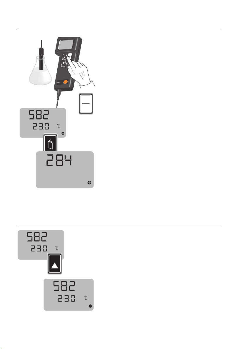
Schließen Sie die Meßzelle an das Gerät an.
Stellen Sie nun die Meßzelle in die Prüflösung
(Leitfähigkeits-Standard oder eigene Lösung mit
bekannter Leitfähigkeit).
Achten Sie darauf,
I
0
- daß die Meßzelle bis zu den Entlüftungslöchern
in der Lösung steht ,
- daß die Luft vollständig aus der Meßzelle entweicht (Meßzelle beim Eintauchen leicht
bewegen).
Gerät einschalten.
BLÄTTER
Mit der
-Taste das Menü "tc"
auswählen.
"0"
Stellen Sie den Temperaturkoeffizient auf
BLÄTTER
Mit der
SELECT
mit
-Taste
bestätigen.
"CAL con"
auswählen und
ein.
Mit ▲▼ den Leitfähigkeits-Wert (Ist-Wert) der
Prüflösung eingeben (siehe Aufdruck auf
Leitfähigkeits-Standard).
5 Sekunden warten, im Display erscheint die
Zellenkonstante. Dieser Wert kann vom
vorgegebenen Wert (z.B. bei älteren Meßzellen)
abweichen, er wird automatisch im Gerät
gespeichert.
BLÄTTER
Mit der
k
in den Meßmodus.
-Taste wechseln Sie nun wieder
2255.. 00
m S/cm
11
Page 12
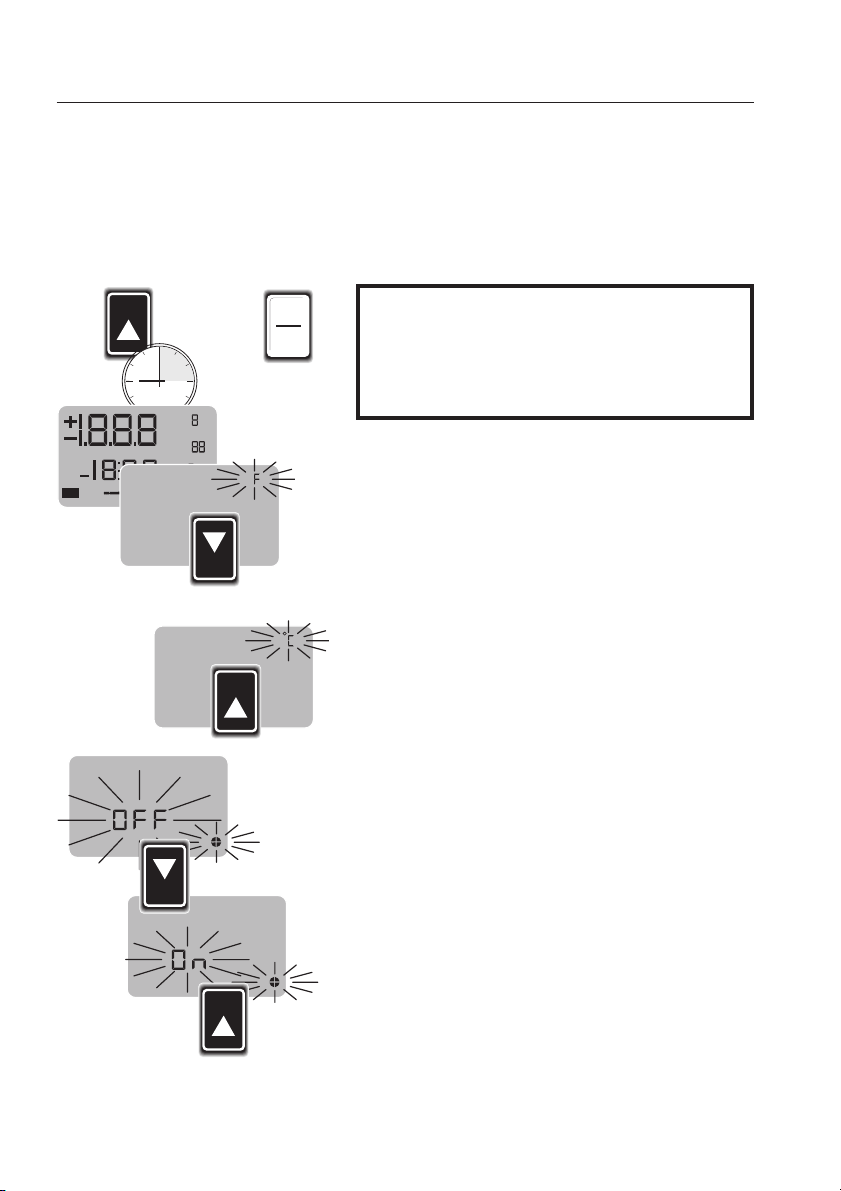
Konfiguration
I
0
Bat
Hold
¡
k
¡
W
Auto
mmS/cm
p
mV
2
pH
Man
/
x
NaCl
X
%/
DIN/NBS
mg/l
Cal
SELECT
SELECT
°C // °°F UUmschaltung
Auto-OOff FFunktion eein- bbzw. aausschalten
240
testo
Meßgröße von °C in °F und umgekehrt.
Außerdem kann die Auto-Off Funktion ein- bzw.
ausgeschaltet werden.
ermöglicht die Umschaltung der
HOLD
+
HOLD
Die Auto-Off Funktion erhöht die Lebensdauer der
Batterie und schont somit die Umwelt.
Achten Sie bei ausgeschalteter Auto-Off
Funktion darauf daß das Gerät immer
ausgeschaltet wird!
Beim Einschalten des Meßgerätes
halten und
HOLD
I/O
kurz antippen.
solange gedrückt halten bis der Segment-
HOLD
gedrückt
test abgeschlossen ist.
Im Display erscheint blinkend
SELECT
Mit
einstellen und mit
die gewünschte Meßgröße
HOLD
Im Display erscheint nun blinkend das
"°C"
bestätigen.
bzw.
"Auto-Off"
"°F".
Symbol.
SELECT
Mit
kann diese Funktion ein- bzw. ausge-
schaltet werden.
12
Eingestellte Funktion mit
HOLD
Das Gerät wechselt nun in den Meßmodus.
HOLD
bestätigen.
Page 13
testo
term
m
S
/c
m
m
S
/
c
m
¡
C
¡
F
te
s
to
®
2
40
H
O
L
D
I
0
testo
term
Pflege uund WWartung
Allgemeine HHinweise
240
testo
keinen besonderen Wartungsintervallen.
Reinigen Sie das Gehäuse mit einem feuchten
Tuch. Schwache Haushaltsreiniger dürfen
verwendet werden.
Zum Reinigen niemals scharfe Reinigungsmittel
oder organische Lösungsmittel verwenden.
Nach dem Einsatz in einer aggressiven Umgebung
ist das Gerät mit einem feuchten Tuch zu reinigen.
Zur Reinigung der Meßzelle das Hüllrohr von der
Meßzelle abziehen.
ist wartungsfrei und unterliegt daher
testo
term
Die darunterliegenden Elektroden mit einer
weichen Bürste reinigen.
Prüfen Sie ob die Entlüftungslöcher sowie das Hüllrohr sauber sind.
Das Hüllrohr bis zum Anschlag auf die Meßzelle
schieben.
In anwendungsbezogenen Abständen sollte die
Zellenkonstante der Meßzelle mit dem Leitfähigkeits-Standard (Zubehör) überprüft werden.
Bat
Hold
X
m
Cal
V
/
m
¡
p
m
p
DIN/NBS
S
H
2
/c
NaCl
m
%/
mg/l
x
¡
M
a
k
A
n
u
W
t
o
Beachten Sie, daß die Schutzart IP 54 nur bei
gestecktem Originalstecker gewährleistet wird.
Niemals mit einem Wasserstrahl reinigen.
13
Page 14
Pflege uund WWartung
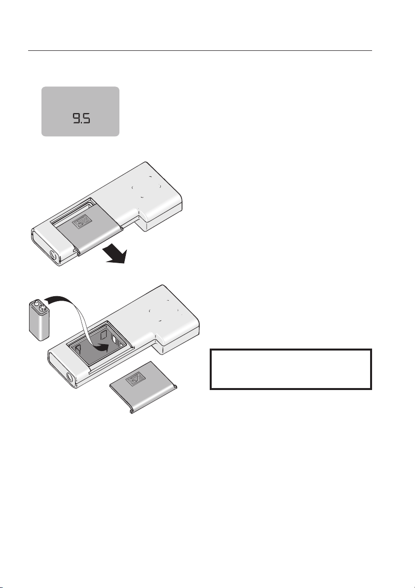
Batteriewechsel
Die Batteriespannung wird beim Einschalten des
Gerätes, nach dem Funktionstest, angezeigt und
Bat
kann somit jederzeit überprüft werden.
Sinkt die Batteriespannung während der Anwendung unter einen zul. Wert, so erscheint das
"BAT"
-Symbol blinkend im Display.
Ist die Batteriespannung nicht mehr ausreichend,
für den einwandfreien Betrieb des Gerätes,
schaltet das Gerät automatisch ab.
Batteriefach öffnen.
Verbrauchte Batterie herausnehmen und neue Batterie, Typ 9V (IEC 6 F 22) einsetzen
(Polung beachten).
14
Beim Batteriewechsel
ist darauf zu achten, daß die Dichtung
nicht beschädigt wird.
Page 15
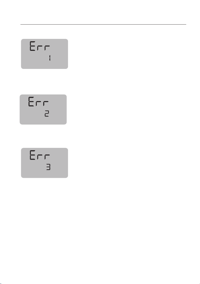
Fehlermeldungen
ERROR 11-33
Meßbereich LLF üüberschritten
- Mögliche Ursachen und • Abhilfen:
- Leitfähigkeit > 2000 mS/cm.
- Zellenkonstante zu klein
• Meßzelle mit größerer Zellenkonstante
verwenden.
Temp. BBereich ddes GGerätes üüberschritten.
- Mögliche Ursachen und • Abhilfen:
- Temperatur < -50 °C oder > +150 °C.
• Fühler aus dem Meßmedium entfernen.
Temperaturbereich bbei nnW-KKomp
Meß- ooder TTemperaturbereich bbei
NaCL-BBerechnung üüberschritten.
- Mögliche Ursachen und • Abhilfen:
bei Leitfähigkeit und Kompensation nach nW
- Temperatur liegt nicht im zulässigen
Bereich 0...+50 °C.
• Temperatur dem zulässigen Bereich
anpassen.
bei Leitfähigkeit und linearer
Temperaturkompensation
- zur gegebenen Temperatur falscher TK
eingestellt, die Temperatur ist zu niedrig ,
bzw. der TK zu hoch.
• Temperaturkoeffizient überprüfen
entsprechenden TK im Gerät speichern
bei NaCL-Bestimmung
- Leitfähigkeit zu hoch (> 230 mS/cm)
• gesättigte Lösung (höhere Werte nicht
möglich)
ensation,
15
Page 16

Fehlermeldungen
ERROR 44+7
Zellenkonstante aaußerhalb ddes
Bereiches 00…15 ccm
-11
Fehler bei der Ermittlung der Zellenkonstante in
einer Lösung mit bekannter Leitfähigkeit
- Mögliche Ursachen und • Abhilfen:
- Die Leitfähigkeit stimmt nicht mit dem bei
der Kalibrierung eingestellten Wert überein.
• Kalibrierung mit dem richtigen
Leitfähigkeitswert wiederholen
-1
- Die Zellenkonstante ist > 15 cm
.
• Andere Meßzelle verwenden.
Interner GGeräte FFehler
- Mögliche Ursachen und • Abhilfen:
- Meßgerät defekt.
• Gerät zum Testo-Service geben.
16
Page 17

Gerät
Meßbereich:
Technische DDaten
..............................................0...2000 mS/cm
-50...+150 °C
1mg/l...200 g/l (NaCl)
Auflösung:
Genauigkeit
Leitfähigkeit..........................................................1 % v.Mw.
Temperatur.........................................±0,4 °C (-50...-25 °C)
Salzgehaltbestimmung (NaCl) ..........................1,2 % v. Mw.
Temperaturkompensation:
Temperaturkoeffizient:
Z
ellenkonstante:
Betriebstemperatur:
Lager-//Transporttemperatur:
Anzeige:
..................................................max. 0,1 µS/cm
0,1 °C (°F)
0,1 mg/l
± 1 Digit
±0,2 °C (-25…+75 °C)
±0,4 °C (+75…+100 °C)
±0,5 % v. Mw. (+100…+150 °C)
..............................automatisch
.....................................0...5 % / °C
• liniare Kompensation
• Kompensation gemäß
der nicht-linearen
Funktion natürlicher Wässer
nach DIN 38404
0…50 °C
.............................................0…15 (1/cm)
..........................................0…+40 °C
.........................-20…+70 °C
................................................................zweizeilig
Anschlüsse:
Batteries
Gewicht:
Sonstiges:
tandzeit:
................................................180 g (inkl. Batterie)
.........................................Mini-DIN-Buchse für
oder Temperaturfühler (testo
...................................................ca. 60 h
..............................................Low.-Batt.-Anzeige
Leitfähigkeits-Meßzellen
110
• automatische Abschaltung
• automatische Meßbereichsumschaltung (Leitfähigkeit)
• (°C - °F Umschaltung)
• Gehäusematerial ABS
• Schutzart IP 54
17
)
Page 18

Technische DDaten
Meßzellen/Temperaturfühler
Art Typ Beschreibung MMeßbereich
07 Universal-LLeitfähigkeitsmeßzelle
4-Elektroden-Technik
- 1 µS/cm...200 mS/cm
- 0...+ 60 °C
Elektrodenmaterial: Edelstahl
10 Präzisions-LLeitfähigkeitsmeßzelle
NaCl mmg/l •• °°C
µµS/cm •• mmS/cm
4-Elektroden-Technik
- 1 µS/cm...300 mS/cm
- 0...+ 60 °C
Elektrodenmaterial: Graphit
02
Tauch-/Einstechfühler
09
Oberflächenfühler
°C
22
Lebensmittelfühler
70
Laborfühler mit Glasrohr
- - 50...+ 150 °C
99
- t
= 6 sec.
- - 50...+ 150 °C
99
= 25 sec.
- t
- - 50...+ 150 °C
99
= 10 sec.
- t
- - 50...+ 150 °C
99
= 20 sec.
- t
Meßgerät testo 240............................................................12 Monate
Garantie
Leitfähigkeits-Meßzellen .....................................................12 Monate *
Temperaturfühler................................................................12 Monate
* auf Herstellungsmängel
Bei ÖÖffnen ddes GGerätes, uunsachgemäßer BBehandlung ooder GGewaltanwendung eerlö-
schen ddie GGewährleistung
sansprüche!
18
Page 19

Bestelldaten
Gerät Best.-NNr.
testo 240................................................................................................
testo 240-Set 1(mit Universal-Leitfähigkeits-Meßzelle) ............................
testo 240-Set 2 (mit Präzisions-Leitfähigkeits-Meßzelle)..........................
Meßzellen uund FFühler
Leitfähigkeits-Meßzelle Typ 07 ms µS/cm • mS/cm • °C...............
Leitfähigkeits-Meßzelle Typ 10 ms µS/cm • mS/cm • °C...............
Tauch/Einstechfühler Typ 02 T °C............................................
Oberflächenfühler Typ 09 T °C............................................
Lebensmittelfühler Typ 22 T °C............................................
Laborfühler Typ 70 T °C............................................
Zubehör
Leitfähigkeits-Standard (0,01 mol/l KCI) 100 ml .......................................
Koffer Compact LF..................................................................................
Ersatzglas für Laborfühler (0613.7011) ....................................................
0560.2404
0563.2405
0563.2406
0650.3023
0650.3024
0613.0211
0
613.9911
0613.2211
0613.7011
0554.2334
0516.0230
0554.7072
19
Page 20

Anhang
Funktionsprinzip dder LLeitfähigkeitsmeßzelle
Es liegt an der Meßzelle, den Zusammenhang zwischen Leitwert bzw. Widerstand und dem
Leitfähigkeitswert herzustellen. Dies geschieht
dadurch, daß die Meßzelle bedingt durch ihre Form
(Länge und Querschnitt) die Stromleitung begrenzt.
Das Verhältnis der Länge zu dem Querschnitt wird
als Zellenkonstante bezeichnet. Neben dieser geometrischen Größe ist eine Meßzelle gezeichnet
durch das Polarisationsverhalten an ihren Elektrodenflächen (→ die, sich an den Elektroden abschei-
denden Ionen und die Konzentrationsänderung der
Lösung an den Elektroden bewirken eine elektromotorische Gegenkraft, die den Stromdurchgang
schwächt und die Leitfähigkeit der Lösung kleiner
erscheinen läßt). Polarisationseffekte verringern
sich mit steigender Meßfrequenz und mit steigender Elektrodenfläche. Außerdem spielt das Elektrodenmaterial eine wesentliche Rolle (auch in Bezug
auf die Einstellzeit).
Die von uns angebotenen Meßzellen mit
4-Elektrodentechnik nutzen die Tatsache, daß
Polarisation nur an Elektroden auftritt, von denen
ein Stromübergang zum Elektolyten stattfindet.
Diese Bauform benötigt jedoch ein größeres Probenvolumen als herkömmliche 2-Elektroden-Meßzellen
20
Page 21

Anhang
Temperaturkoeffizienten aausgewählter LLösungen
Der Temperaturkoeffizient αTist definiert
als die Änderung der spezifischen Leitfähigkeit, bezogen auf die Leitfähigkeit der
Referenztemperatur (25 °C):
a
=
1
100%
25
Die nebenstehend tabellierten Werte sind
mittlere Temperaturkoeffizienten für 18 °C
T 26 °C. Sie wurden auf eine Referenztemperatur von 25 °C umgerechnet
(s. "Grundsätzliches zur linearen Temperaturkompensation"), damit Sie sie ohne
weitere Manipulation in Ihr Testo-Gerät
eingeben können.
Literaturnachweis:
Tabellierte Werte von Landold-Börnstein,
Zahlenwerte und Funktionen
Konzentration
c
Mol/l
in
p
Verbindung
%/°C
in
HCI c = 1,405 1,42
3
HNO
4
H2SO
(SO3- 100,14 2,48
Überschuß) 101,12 2,55
NaOH c = 0,641 1,71
KOH c = 0,777 1,65
NaCl c = 0,884 1,88
KCI c = 0,691 1,76
3
NaNO
3
KNO
4
Na2SO
4
K2SO
NH4OH c = 0,059 2,10
NH4Cl c = 0,984 1,74
3
NH4NO
(NH4)2SO
4
Gew.-%%
in
4,420 1,40
11,303 1,37
c = 1,017 1,33
5,873 1,27
13,640 1,41
p = 96,00 2,13
99,66 2,61
99,98 2,55
6,122 2,47
15,323 4,66
5,583 1,82
10,695 2,36
3,924 1,88
5,421 2,00
2,208 1,59
3,213 1,49
c = 0,607 1,91
2,688 1,87
4,329 1,91
c = 0,509 1,82
1,626 1,77
2,496 1,71
c = 0,25 2,06
1,0 2,13
1,206 2,17
c = 0,298 1,88
0,5 1,81
0,620 1,78
2,307 2,13
8,87 2,49
2,924 1,53
5,003 1,39
c = 0,637 1,78
2,711 1,59
7,664 1,41
c = 0,25 1,89
1,0 1,77
1,5 1,72
(22 ±4)
100%
25
21
Page 22

Anhang
Grundsätzliches zzur llinearen TTemperaturkompensation
näherungsweisen
Zur
beliebiger Temperatur gemessenen, Leitfähigkeit in
dieselbe bei Referenztemperatur (z.B. 25 °C),
benutzt man den, nach folgender Gleichung
definierten , Temperaturkoeffizienten
(s. DIN 38404 Teil 8):
KTMK
=
a
TR
K
TR
Umrechnung einer, bei
1
TR
TMT
100%
R
αTRTemperaturkoeffizient bei
der Referenztemperatur
T
Referenztemperatur
R
(25 °C beim
T
Temperatur
M
der gemessenen Probe
K
elektrische Leitfähigkeit bei
TR
der Referenztemperatur
K
elektrische Leitfähigkeit bei
TM
der Meßtemperatur
testo
240
)
abhängig vvon
α ist
Konzentration
Ionen, aber auch von der
In einschlägigen Tabellenwerken (z.B. Landold
Börnstein) sind α-Werte für einige Salz-, Säureund Alkalilösungen für verschiedene Meßbedingungen zu finden.
Beziehen sich die Temperaturkoeffizienten auf eine
andere, als die gewünschte Referenztemperatur, hat man die Möglichkeit, sie nach
a
TR2
folgender Gleichung umzurechnen.
Man kann den Temperaturkoeffizienten für seinen
speziellen Anwendungsfall auch selbst ermitteln.
Dazu mißt man die Leitfähigkeiten einer gegebenen
Lösung bei den Temperaturen T
nahe der Referenztemperatur liegen sollte.
αTRergibt sich nach der Gleichung:
der in der Lösung befindlichen
a
=
a
+
1
100%
TR1
der
TR1
Art
und der
Temperatur
T
T
R2
R1
selbst.
und T2, wobei T
1
2
22
KT2K
=
a
TR
K
T
T
T1
2
1
KT2K
+
T1
T
T1
100%
T
R
1
Page 23

testo 240
Conductivity measuring instrument
Bedienungsanleitung de
Instruction manual en
Page 24

Contents
Instrument ddescription
Operation iinstructions
Safety iinstructions
Instructions oof uuse
Connection of probe .................................................................6
Switching on the instrument ......................................................7
Auto off function........................................................................7
Storing the cell constant............................................................8
Setting the temperature coefficient............................................9
Conductivity mm
HOLD function ........................................................................10
Determining tthe ccell cconstant
Configuration
°C/°F conversion • Switching off the auto off function .............12
Care aand mmaintenance
General remarks......................................................................13
Battery replacement................................................................14
Error mmessages
ERROR 1-3.............................................................................15
ERROR 4+7 ............................................................................16
Techni
cal ddata
Instrument...............................................................................17
Conductivity measuring cells ...................................................18
Temperature probes................................................................18
Warranty .................................................................................18
easurement
....................................................................................12
.................................................................................15
..................................................................................17
.......................................................................3
........................................................................5
..............................................................................5
..............................................................................6
..............................................................10
..........................................................11
.....................................................................13
Ordering ddata
Appendix
....................................................................................19
...........................................................................................19
Principle of meas. of the conductivity measuring cells ...............20
Temperature coefficients of selected solutions ........................21
Basic information on linear temperature compensation............22
Measuring iinstrument cconforms
with EEN 550 0081-11 ++ EEN 550 0082-11
2
Page 25

testo
term
mS/cm mS/cm
¡C / ¡F
testo
®
240
SELECT
HOLD
I
0
Bat
Hold
¡
k
¡
W
Auto
m
mS/cm
p
m
V
2
pH
Man
/
x
NaCl
X
%/
D
IN
/N
B
S
mg/l
Cal
testo
term
Keyboard
Display
Instrument ddescription
Conductivity measuring cell
Connection socket
Conductivity meas. cell
Temperature probe
Rings
Meas. electrode
Temperature
sensor
Air vents
Battery
compartment
Temperature probe
Cable duct
3
Page 26

mmS/cm
B
k
NaCl mg/l
Instrument ddescription
Display //keyboard
1st line
Display of measured value (µS/cm, mS/cm, NaCl
mg/l - °C/°F for measurements with temperature
probe) and menu.
2nd line
Display of temperature value
at
Hold
Cal
HOLD
%/
I
0
Battery control
When instrument is switched on: battery voltage
During use of instrument: low battery warning
"HOLD" function activated
Calibration menu activated
"Cell constant" calibration menu
Temperature coefficient
Measurement with temperature probe
Auto off function
HOLD
key (hold measured values or set values
with manual input function)
ON/OFF
key
PAGE
key
SELECT
4
(call up individual menus)
SELECT
manual input function)
key (select menus or set values with
Page 27

Operation iinstructions
testo
term
m
S
/
c
m
m
S
/
c
m
¡
C
¡F
te
st
o
®
24
0
H
O
L
D
I
0
240
testo
measures conductivity, salt content and temperature in aqueous solutions.
240
Bat
Hold
X
m
Cal
V
/
m
¡
p
m
p
DIN/NB
S
H
2
/c
NaCl
m
S
%/
mg/l
x
¡
M
a
k
A
n
u
W
t
o
testo
is a simple to clean, rugged and easy to use conductivity and temperature measuring instrument
covering the range 0 to 2000mS/cm, 1 to
200 mg/l NaCl as well as -50 to +150 °C (-60 to
+300 °F).
The water-resistant housing (IP 54 protection, showerproof and dust protection), its easy use and the
different conductivity measuring cells and temperature probes makes the instrument suitable for a wide range of applications
Safety iinstructions
Please rread bbefore
using iinstrument!
Do not measure on live parts!
This instrument is not suitable
for use in the medical branch!
Observe permissible storage, transport and operating temperature
(e.g. protect measuring instrument from direct sunlight).
IP 54 protection is only guaranteed when probes are connected!
If the instrument is opened, improperly handled or if force is applied,
no warranty will be granted!
5
Page 28

Instructions oof uuse
te
s
to
te
r
m
mS/cm mS/cm
¡C / ¡F
te
sto
®
2
40
S
E
L
E
C
T
H
O
L
D
I
0
B
a
t
H
o
ld
¡
k
¡
W
Auto
mmS/cm
p
m
V
2
pH
Man
/
x
N
a
C
l
X
%/
D
I
N
/
N
B
S
m
g
/l
C
a
l
te
s
to
te
rm
mS/cm mS/cm
¡C / ¡F
te
sto
®
2
40
S
E
L
E
C
T
H
O
L
D
I
0
B
a
t
H
o
ld
¡
k
¡
W
Auto
mmS/cm
p
m
V
2
pH
Man
/
x
N
a
C
l
X
%/
D
I
N
/
N
B
S
m
g
/l
C
a
l
te
s
to
te
rm
mS/cm mS/cm
¡C / ¡F
te
sto
®
2
40
S
E
L
E
C
T
H
O
L
D
I
0
B
a
t
H
o
ld
¡
k
¡
W
Auto
mm
S/cm
p
m
V
2
pH
Man
/
x
N
a
C
l
X
%/
D
I
N
/
N
B
S
m
g
/l
C
a
l
te
s
to
te
rm
mS/cm mS/cm
¡C / ¡F
te
sto
®
2
40
S
E
L
E
C
T
H
O
L
D
I
0
B
a
t
H
o
ld
¡
k
¡
W
Auto
mm
S/cm
p
m
V
2
pH
Man
/
x
N
a
C
l
X
%/
D
I
N
/
N
B
S
m
g
/l
C
a
l
te
s
to
te
rm
mS/cm mS/cm
¡C / ¡F
testo
®
240
S
E
L
E
C
T
H
O
L
D
I
0
B
a
t
H
o
ld
¡
k
¡
W
Auto
m
m
S/cm
p
m
V
2
pH
Man
/
x
N
a
C
l
X
%/
D
I
N
/N
B
S
m
g
/l
C
a
l
te
s
to
te
rm
mS/cm mS/cm
¡C / ¡F
te
sto
®
24
0
S
E
L
E
C
T
H
O
L
D
I
0
B
a
t
H
o
ld
¡
k
¡
W
Auto
m
m
S/cm
p
m
V
2
pH
Man
/
x
N
a
C
l
X
%/
D
I
N
/
N
B
S
m
g
/l
C
a
l
Connection oof pprobes
Connect the conductivity measuring cell to the
socket of the instrument before switching the
instrument on.
Pay attention to the markings (><) on the instrument and the probe plug.
Never pull on the lead when removing the probe!
The measuring cells and temperature probes can
be used loose or attached to the side of the instrument.
6
Page 29

Instructions oof uuse
Bat
Hold
¡
k
¡
W
Auto
p
mV
2
pH
Ma
n
/
x
NaCl
X
%/
DIN/NBS
mg/l
Cal
mS/cm
m
Switching oon tthe iinstrument
Bat
Hold
Bat
Cal
X
¡
2
p
/
V
m
mmS/cm
x
DIN/NBS
mg/l
NaCl
Bat
¡
k
%/
Hold
W
Man
X
Auto
pH
Cal
I
HOLD
0
T
C
E
L
E
S
®
240
testo
testo
term
/cm
S
m
/cm
mS
/ ¡F
¡C
mV
I
0
¡
/
p
2
mmS/cm
DIN/NBS
NaCl
mg/l
¡
%/
k
W
pH
Man
Auto
Switch on the instrument.
A short display and segment test then follows, after
which a battery control test indicates the battery
voltage (see also battery replacement).
x
The instrument is now operational.
The circle disappears from the display at a rate of
The cell constant must be stored in the instrument
2.5 minutes/segment.
When the last segment disappears, the instrument
before the first measurement.
ATTENTION!
switches itself off.
Auto ooff ffunction
Auto ooff ffunction
mS/cm
W
n
If the instrument is not operated for 10 minutes,
the instrument switches off automatically.
7
Page 30

te
mS/cm mS/cm
Storing tthe ccell cconstant
¡
2
p
/
V
m
S/cm
mm
S
B
N
/
N
I
x
D
/l
g
m
l
C
a
N
t
a
B
¡
k
%/
ld
o
H
W
an
M
X
Auto
pH
l
a
C
D
L
O
I
H
0
T
C
E
L
E
S
®
0
to
s
24
te
sto
m
r
te
¡C / ¡F
I
0
m S/cm
x
NaCl mg/l
W
Cal
pH
Man
Auto
%/
Due to reasons of product engineering, the cell
coefficient of the conductivity measuring cell varies.
The cell coefficent indicated on the cable of the
measuring cell to be used, must be stored in the
instrument
before tthe ffirst mmeasurement.
Connected the measuring cell to the instrument
Switch on the instrument.
After the display and segment test, use the page
"CAL"
key to enter the
menu.
Cal
Confirm with the select key, a value is then displayed and
"k"
(coefficient) flashes in the display.
Use the arrow keys (▲▼) to set the cell coefficient
of the measuring cell.
SELECT
Cal
HOLD
k
Wait 5 seconds for the instrument to store this
value and enter the measurement menu.
SELECT
This new value remains stored even after the
instrument has been switched off and can be used
for the next measurement. If the measuring cell is
replaced, the cell constant for this measuring cell
mS/cm
n
W
must be entered and stored.
8
Page 31

Setting tthe ttemperature ccoefficient
te
mS/cm mS/cm
¡
2
p
/
V
m
S/cm
mm
S
B
N
/
N
I
x
D
/l
g
m
l
C
a
N
t
a
B
¡
k
%/
ld
o
H
W
Man
X
Auto
pH
al
C
D
L
O
I
H
0
T
C
E
L
E
S
testo 2240
solutions of 0.0 µS/cm to 2000 mS/cm.This
measuring range contains a variety of different
solutions, each with special temperature
coefficients.
The temperature coefficient (
®
0
4
to
s
2
te
to
s
m
r
e
t
¡C / ¡F
I
0
and
of temperature on the conductivity of the
solution.
is suitable for measurements in
0 %/°C to 5.00%/°C
"nW"
for natural water) describes the influence
In order to obtain accurate results, the coefficients
of the solution should be entered before beginning
m S/cm
a measurement.
2.1 %/°C is the standard Ø value for solutions with
nW"
unknown temperature coefficients, "
is the set-
ting for measurements in natural water (press ▲
once after 5.00 %/°C). (see appendix: " Tempera-
NaCl mg/l
ture coefficients of selected....")
Connect the measuring cell.
Switch on the instrument.
%/
Once the display and segment test has been completed, select the
"tc"
menu (temperature coeffi-
cient) with the page key.
SELECT
HOLD
Set the temperature coefficient with the arrow
keys.
%/
n
W
mS/cm
n
Wait 5 seconds for the instrument to store the
value and enter the measurement menu.
This value remains stored even after the instrument
has been switched off and is available for the next
measurement.
W
9
Page 32

Conductivity mmeasurement
t
e
s
to
te
rm
mS/cm mS/cm
¡C / ¡F
te
s
to
®
2
40
S
E
L
E
C
T
H
O
L
D
I
0
B
a
t
H
o
ld
¡
k
¡
W
Auto
mmS/cm
p
m
V
2
pH
Man
/
x
N
a
C
l
X
%/
D
I
N
/
N
B
S
m
g
/l
C
a
l
Connect the measuring cell to the instrument.
Position the measuring cell in the measuring solution.
Make sure that the solution is up to the air vents ,
and that all the air escapes from the measuring cell
(move the measuring cell gently when
dipping into the solution).
m S/cm
I
0
Switch on the instrument.
Once the segment test and short adaption phase
have been completed, the conductivity value,
based on 25 °C, and temperature are displayed.
The salt content of the solution (NaCl mg/l) can be
x
NaCl mg/l
W
Cal
pH
Man
Auto
calculated by pressing the
(The calculation is as follows:
O + dissolved NaCl contribute to
only H
2
PAGE
key.
conductivity).
The HOLD function enables measured values to be
HOLD ffunction
held in display over a longer period of time. The
AUTO OFF function is then deactivated.
m S/cm
HOLD
Press the HOLD key.
The measured value and the HOLD function are
held in display.
The AAUTO OFF function iis tthus ddeactivated
m S/cm
The current values are displayed by repressing the
HOLD key.
10
Page 33

Determining tthe ccell cconstant
Cal
2255 ..00
Cal
2255 ..00
Cal
sto
te
mS/cm mS/cm
m S/cm
2255 ..00
t
a
B
ld
o
H
X
pH
l
a
C
L
E
S
®
40
2
¡C / ¡F
¡
p
/
V
m
mmS/cm
S
B
/N
N
I
D
m
l
C
a
N
¡
%/
W
Man
Auto
D
L
O
I
H
0
T
C
E
o
t
s
te
m
r
te
SELECT
HOLD
m S/cm
2
x
g/l
k
m S/cm
SELECT
Should you have old sensors or sensors with an
unknown constant, this value must be measured
with a test solution with a know conductivity.
Connect the measuring cell to the instrument.
Position the measuring cell in the test solution
(conductivity standard solution or your own
solution of a known conductivity).
I
0
Make sure
- that the solution is up to the air vents ,
- that all the air escapes from the measuring cell
(move the measuring cell gently when dipping
into the solution).
Switch on the instrument.
Press the
PAGE
key to select the "tc" menu.
Set the temperature coefficient to "0".
Use the
firm with
PAGE
key to select "CAL con" and con-
SELECT
.
Enter the conductivity value of the test solution with
the ▲▼ keys (see lable on standard conductivity
solution).
Wait 5 seconds, the cell coefficient is then displayed. This value can differ from that set value (e.g.
with older measuring cells), it is automatically stored in the instrument.
Cal
2255 ..00
k
m S/cm
Press the
PAGE
key to enter the measuring mode.
11
Page 34

HOLD
I
0
Bat
Hold
¡
k
¡
W
Auto
mmS/cm
p
mV
2
pH
Man
/
x
NaCl
X
%/
DIN/NBS
mg/l
Cal
SELECT
Configuration
°C // °°F cconversion
Switching aauto ooff ffunction oon oor ooff
240
testo
measurement from °C to °F and vice-versa. The
auto off function can also be switched off.
enables the conversion of the unit of
SELECT
+
HOLD
The auto off function increases the battery life and
thus protects the environment. Should the auto off
function be deactivated, do not forget to switch
the instrument off!
Keep the
the instrument and press the
Keep the
HOLD
key pressed when switching on
I/O
HOLD
key pressed until the segment
key once.
test has been completed.
"°C"
or
°F"
flashes in the display.
Set the required unit of measurement with the
SELECT
The "
Auto-Off"
SELECT
key and confirm with
symbol flashes in the display.
can be used to switch this function on or
HOLD
.
off.
12
HOLD
.
HOLD
Confirm the function with
The instrument now switches to the measuring
mode.
Page 35

Care aand mmaintenance
testo
term
testo
term
m
S
/c
m
m
S
/
c
m
¡
C
¡
F
te
s
to
®
2
40
H
O
L
D
I
0
testo
term
General rremarks
240
testo
fore not subject to particular maintenance intervals.
Clean the housing with a damp cloth. Weak
household cleaners can be used.
Strong detergents or solvents should never be used
After use in an aggressive environment, the instrument should be cleaned with a damp cloth.
Pull back the cable duct from the measuring cell, in
order to clean the electrodes.
Clean the electrodes with a soft brush.
Check whether the air vents and the cable duct are
clean.
requires no maintenance and is there-
for cleaning the measuring instrument.
Push the cable duct back into place.
The cell coefficient of the measuring cell should be
tested with the conductivity standard solution
(accessories) at intervals which depend on the type
of application.
Bat
Hold
X
m
Cal
V
/
m
¡
p
m
p
DIN/NBS
S
H
2
/c
NaCl
m
%/
mg/l
x
¡
M
a
k
A
n
u
W
t
o
Please note that IP 54 protection is only
guaranteed when original plugs are connected.
Never clean with a water jet.
13
Page 36

Care aand mmaintenance
Battery rreplacement
Bat
The battery voltage is displayed after the segment
test each time the instrument is switched on and
can, thus, be checked regularly.
Should the battery voltage drop below the
"BAT"
permissible value,
Should the battery voltage no longer be sufficient
to guarantee the correct functioning of the instrument, the measuring instrument switches off automatically.
Open the battery compartment.
Remove the old battery and insert the new
battery, type 9V (IEC 6F 22)
(Observe polarization).
When replacing the battery, take care not
" flashes in the display.
to damage the ring.
14
Page 37

Error mmessages
ERROR 11-33
Conductivity mmeas. rrange hhas bbeen eexceeded
- Possible causes and • remedies:
- conductivity > 2000 mS/cm.
- conductance too high for sensor used.
• use sensor with greater cell constant.
Temp. rrange oof tthe iinstrument hhas bbeen eexcee-
ded.
- Possible causes and • remedies:
- temperature < -50 °C /-60 °F or > +150 °C/
+300 °F.
• remove probe from the substance being
measured.
perature rrange dduring nnW ccompensation,
Tem
measuring rrange oor ttemperature rrange dduring
calculation oof NNaCl h
- Possible causes and • remedies:
with conductivity and nW compensation
- temperature is not within permissible
range 0 to +50 °C (+32 to +120 °F).
• adapt the temperature to the permissible
range
has bbeen eexceeded ..
with conductivity and temperature compensation
- incorrect tc setting for given temperature,
the temperature is too low or the tc too high.
, • check temperaure coefficient, store
corresponding tc in instrument
with NaCl measurement
- conductivity too high (> 230 mS/cm)
• saturated solution (higher values not
possible).
15
Page 38

Error mmessages
ERROR 44+7
Cell cconstant ooutside tthe rrange 00 tto 115 ccm
-11
Error in measuring the cell constant in a solution of
a known conductivity
- Possible causes and • remedies:
- the solution was not at a temperature of
+25 °C/+75 °F.
• adapt temperature.
- the conductivity is not that of the value set
during calibration.
• reset the conductivity value of the test
solution in the instrument.
-1
- the cell constant is > 15 cm
.
• use other measuring cells.
Internal iinstrument eerror
- Possible causes and • remedies:
- faulty measuring instrument.
• return instrument to Testo’s service
department.
16
Page 39

Instru-
ment
Measuring rrange:
Technical ddata
....................................0 to 2000 mS/cm
-50 to +150 °C/-60 to +300°F
1mg/l to 200 g/l (NaCl)
Resolution:
Accuracy:
Conductivity........................................................1 % of m.v.
Temperature ......±0.4 °C/0.7 °F (-50 to -25 °C/-60 to-15 °F)
Measurement of salt content (NaCl) .................1.2 % of m.v.
Temperature ccompensation:
Temperature ccoefficient:
Cell cconstant:
Ambient ttemperature:
Storage aand ttransport ttemperature:
Display:
.................................................max. 0.1 µS/cm
0.1 °C (°F)
0.1 mg/l
± 1 digit
±0.2 °C/0.4 °F (-25 to +75 °C/-15 to +165 °F)
±0.4 °C/0.7 °F (+75 to +100 °C/+165 to +210 °F)
±0.5 % of m.v. (+100 to +150 °C/+210 to +300 °F)
..............................automatic
...............................0 to 5 % / °C
• linear compensation
• compensation according to the
non-linear function of natural water
DIN 38404
0 to 50 °C/+32 to +120 °F
................................................0 to 15 (1/cm)
.............0 to +40 °C/+32 to +105 °F
...........-20 to +70 °C/.
4 to +160 °F
..................................................................two lines
Connections
Battery llife:
Weight:
Other:
..........................................mini-DIN socket for
conductivity measuring cells
or temperature probes (
......................................................approx. 60 h
...................................................180 g (incl. battery)
....................................................low battery warning
• automatic conversion of meas.
range (conductivity)
• (°C - °F conversion)
• housing material ABS
• IP 54 protection
testo
• auto-off
110
17
)
Page 40

Measuring ccells/temperature pprobes
Type Description MMeas. rrange
07 Universal cconductivity mmeasuring ccell
4 electrode technology
electrode material: stainless steel
10 Precision cconductivity mmeasurin
4 electrode technology
µµS/cm •• mmS/cm
NaCl mmg/l •• °°C/°F
02
99
°C/°F
22
70
electrode material: graphite
Immersion/penetration probe
Surface probe
Food probe
Laboratory probe with glass tube
g ccell
- 1 µS/cm to 200 mS/cm
- 0 to + 60 °C (+32 to+140 °F)
- 1 µS/cm to 300 mS/cm
- 0 to + 60 °C (+32 to+140 °F)
- - 50 to + 150 °C(-60 to +300 °F)
- t
- - 50 to + 150 °C(-60 to +300 °F)
- t
- - 50 to + 150 °C(-60 to +300 °F)
99
- t
- - 50 to + 150 °C(-60 to +300 °F)
99
- t
Technical ddata
99
= 6 sec.
99
= 25 sec.
= 10 sec.
= 20 sec.
Warranty
testo 240 measuring instrument.........................................12 months
Conductivity measuring cells ..............................................12 months
Temperature probes...........................................................12 months
If tthe iinstrument iis oopened, iimproperly hhandled oor iif fforce iis aapplied,
now wwarranty wwill bbe ggrante
18
d!
Page 41

Ordering ddata
Instrument Part nno.
testo 240................................................................................................
testo 240 set 1(with universal conductivity measuring cell)......................
testo 240 set 2 (with precision conductivity measuring cell) ....................
Measuring ccells aand pprobes
Conductivity meas. cell no. 07 µS/cm • mS/cm • °C/°F ............
Conductivity meas. cell no.10 µS/cm • mS/cm • °C/°F ............
Immersion/penetration probe no. 02 °C/°F..........................................
Surface probe no. 99 °C/°F..........................................
Food probe no. 22 °C/°F..........................................
Laboratory probe no. 70 °C/°F..........................................
Accessories
Conductivity standard solution (0.01 mol/l KCI) 100 ml............................
Carrying case for conductivity instrument/Compact Class ......................
Spare glass tube for laboratory probe (0613.7011)..................................
0560.2404
0563.2405
0563.2406
0650.3023
0650.3024
0613.0211
0613.9911
0613.2211
0613.7011
0554.2334
0516.0230
0554.7072
19
Page 42

Appendix
Principle oof mmeas. oof tthe cconductivity mmeasuring ccells
It is up to the sensor to produce the connection
between the conductance or resistance and the
conductivity value. This is done by the fact that the
form of the sensor (length and cross-section) limits
the conduction of the current. The relation of the
length to the cross-section is described as a cell
constant. Alongside this geometric parameter, the
sensor is also marked by the polarisation behaviour
on its electrode surfaces (’ the ions which separate
from the electrodes and the change in
concentration of the solution at the electrodes
cause an electromotive counterforce, which weakens the passage of flow and lets the conductivity
of the solution seem smaller than it actually is).
Polarisation effects reduce with an increasing measuring frequency and an increasing electrode surface. The electrode material plays an additional
important role (also in relation to the response
time).
The sensors with the 4 electrode technology,
which we offer, have taken advantage of the fact
that polarisation only occurs on electrodes where
the current leaks into the electrolyte. This 4 electrode structure, however, requires a larger
volume of samples than the usual 2 electrode sensors.
20
Page 43

Appendix
100%
Temperature ccoefficients oof sselected ssolutions
The temperature coefficient αTis defined
as the change in the specific conductivity,
in relation to the conductivity of the reference temperature (25 °C/+75°F):
a
=
1
100%
25
The values in the table opposite are mean
temperature coefficients for 18 °C T
26 °C. They have been converted to a
reference temperature of 25 °C (see
"Basic information on linear temperature
compensation"), so that you can enter
them in your Testo instrument without further ado.
Source of literature:
Table from Landold-Börnstein, "Zahlenwerte und Funktionen"
concentration
c
Mol/l
in
Compoundpin
%/°C
in
HCI c = 1.405 1.42
3
HNO
4
H2SO
(excess 100.14 2.48
SO3) 101.12 2.55
NaOH c = 0.641 1.71
KOH c = 0.777 1.65
NaCl c = 0.884 1.88
KCI c = 0.691 1.76
3
NaNO
3
KNO
4
Na2SO
4
K2SO
NH4OH c = 0.059 2.10
NH4Cl c = 0.984 1.74
3
NH4NO
(NH4)2SO
4
weight.-%%
4.420 1.40
11.303 1.37
c = 1.017 1.33
5.873 1.27
13.640 1.41
p = 96.00 2.13
99.66 2.61
99.98 2.55
6.122 2.47
15.323 4.66
5.583 1.82
10.695 2.36
3.924 1.88
5.421 2.00
2.208 1.59
3.213 1.49
c = 0.607 1.91
2.688 1.87
4.329 1.91
c = 0.509 1.82
1.626 1.77
2.496 1.71
c = 0.25 2.06
1.0 2.13
1.206 2.17
c = 0.298 1.88
0.5 1.81
0.620 1.78
2.307 2.13
8.87 2.49
2.924 1.53
5.003 1.39
c = 0.637 1.78
2.711 1.59
7.664 1.41
c = 0.25 1.89
1.0 1.77
1.5 1.72
(22 ±4)
25
21
Page 44

Appendix
Basic iinformation oon llinear ttemperature
compensation
approximate
1
T
T
M
R
conversion of a
100%
In order to enable an
conductivity, measured at any temperature, into
that at the reference temperature (e.g. 25 °C/
+75 °F), the temperature coefficients are used
according to the following equation
(see DIN 38404 part 8):
K
TMKTR
=
a
TR
K
TR
αTRTemperature coefficient at
the reference temperature
T
Reference temperature
R
(25 °C with
T
Temperature
M
of the measured sample
K
Electric conductivity at the
TR
reference temperature
K
Electric conductivity at the
TM
temperature of measurement
testo
240
)
dependent oon
α is
concentration
but also on
In relevant tables (such as Landold Börnstein), α
values can be found for salty, acidic and alcaline
solutions in different types of measuring
conditions.
Should the temperature coefficients be based on
another reference temperature than that required, it
is possible to convert them with the following
a
TR2
equation.
You can also determine temperature coefficients
for your own particular application yourself. For this
you need to measure the conductivity of a given
solution at temperatures T
close to the reference temperature.
α
can be measured with the equation:
TR
of the ions present in the solution,
temperature
=
+
1
the
a
TR1
a
TR1
100%
type
and the
itself .
T
T
R2
R1
and T2, T2should be
1
22
a
TR
T
K
1
=
K
T1
T
2
K
T2
T2
K
T1
K
+
T1
T
R
T
100%
1
Page 45

Page 46

Page 47

Page 48

testo AG
Postfach 11 40, 79849 Lenzkirch
Testo-Straße 1, 79853 Lenzkirch
Telefon: (07653) 681-0
Fax: (07653) 681-100
E-Mail: info@testo.de
Internet: http://www.testo.com
0973.2620/09.97/wh/T/28.07.2004
 Loading...