

Terex PT-100G Forestry, PT100G Service Manual

PT-100G
PT-100G Forestry
Part Number: 2076-286
Printed (8-10)
Service Manual
Compact Track Loader


Table of Contents
1. Product Safety
Chapter Overview . . . . . . . . . . . . . . . . . . . . . 1-1
Safety Messages . . . . . . . . . . . . . . . . . . . . . 1-1
Information Messages . . . . . . . . . . . . . . . . . 1-1
Basic Precautions . . . . . . . . . . . . . . . . . . . . . 1-1
Safety Labels . . . . . . . . . . . . . . . . . . . . . . . 1-1
Protective Equipment . . . . . . . . . . . . . . . . 1-1
Entering and Exiting . . . . . . . . . . . . . . . . . 1-2
Lifting . . . . . . . . . . . . . . . . . . . . . . . . . . . . . 1-2
Hot Fluids and Components . . . . . . . . . . . 1-2
Corrosion Inhibitor . . . . . . . . . . . . . . . . . . . 1-2
Batteries . . . . . . . . . . . . . . . . . . . . . . . . . . 1-2
Pressurized Items . . . . . . . . . . . . . . . . . . . 1-2
Repair . . . . . . . . . . . . . . . . . . . . . . . . . . . . . . 1-3
Attachments . . . . . . . . . . . . . . . . . . . . . . . . . 1-4
Machine Labels and Decals . . . . . . . . . . . . . 1-4
Product Identification Number . . . . . . . . . . 1-4
Safety Labels . . . . . . . . . . . . . . . . . . . . . . . 1-4
2. Technical Specifications
Specifications . . . . . . . . . . . . . . . . . . . . . . . . 2-1
Engine . . . . . . . . . . . . . . . . . . . . . . . . . . . . 2-1
Transmission . . . . . . . . . . . . . . . . . . . . . . . 2-1
Drive Pumps . . . . . . . . . . . . . . . . . . . . . . 2-1
Charge Pump . . . . . . . . . . . . . . . . . . . . . 2-1
Drive Motors . . . . . . . . . . . . . . . . . . . . . . . . . 2-1
Controls . . . . . . . . . . . . . . . . . . . . . . . . . . . . 2-1
Auxiliary Pump . . . . . . . . . . . . . . . . . . . . . . . 2-1
Lift Arm Control Valve . . . . . . . . . . . . . . . . . . 2-1
Oil Cooler . . . . . . . . . . . . . . . . . . . . . . . . . . . 2-1
Critical Torque Specifications . . . . . . . . . . . . 2-1
Service Tools . . . . . . . . . . . . . . . . . . . . . . . . 2-1
3. Circuit Diagrams
Chapter Overview . . . . . . . . . . . . . . . . . . . . . 3-1
Hydraulic Charge Circuit . . . . . . . . . . . . . . . . 3-1
Hydraulic Auxiliary Circuit . . . . . . . . . . . . . . . 3-2
Hydraulic Control Circuit . . . . . . . . . . . . . . . . 3-3
Hydraulic Drive Circuit . . . . . . . . . . . . . . . . . 3-4
Lift Arm Control Valve . . . . . . . . . . . . . . . . . . 3-5
Hydraulic Solenoid Blocks . . . . . . . . . . . . . . 3-6
Electrical Attachment Outlet . . . . . . . . . . . . . 3-7
4. Maintenance
Chapter Overview . . . . . . . . . . . . . . . . . . . . . 4-1
Personal Safety . . . . . . . . . . . . . . . . . . . . . . 4-1
Lift-Arm Brace . . . . . . . . . . . . . . . . . . . . . . . . 4-1
Tilt-up Cab . . . . . . . . . . . . . . . . . . . . . . . . . . 4-2
Jacking Procedure . . . . . . . . . . . . . . . . . . . . 4-2
Grease Fittings . . . . . . . . . . . . . . . . . . . . . . . 4-3
Undercarriages . . . . . . . . . . . . . . . . . . . . . . . 4-3
Track Tension . . . . . . . . . . . . . . . . . . . . . . . . 4-4
Planetary Oil Change . . . . . . . . . . . . . . . . . . 4-4
Drive Sprocket Rollers . . . . . . . . . . . . . . . . . 4-5
Track Removal . . . . . . . . . . . . . . . . . . . . . . . 4-6
Track Installation . . . . . . . . . . . . . . . . . . . . . . 4-8
Air Cleaner . . . . . . . . . . . . . . . . . . . . . . . . . . 4-10
Fuel Filter . . . . . . . . . . . . . . . . . . . . . . . . . . . 4-11
Water Separator . . . . . . . . . . . . . . . . . . . . . . 4-11
Belt Removal/Installation . . . . . . . . . . . . . . . 4-11
Engine Oil/FIlter Change . . . . . . . . . . . . . . . 4-12
Engine Oil Specifications . . . . . . . . . . . . . . . 4-13
Oil Level Check . . . . . . . . . . . . . . . . . . . . . . 4-13
Hydraulic Fluid/Filter Change . . . . . . . . . . . . 4-14
Radiator/Oil Cooler (cleaning) . . . . . . . . . . . 4-15
Engine (cleaning) . . . . . . . . . . . . . . . . . . . . . 4-15
Case Drain Filter . . . . . . . . . . . . . . . . . . . . . . 4-16
Fuse Panel . . . . . . . . . . . . . . . . . . . . . . . . . . 4-16
Maintenance Schedule . . . . . . . . . . . . . . . . . 4-17
5. Machine Controls and Instrumentation
Chapter Overview . . . . . . . . . . . . . . . . . . . . . 5-1
Machine Controls . . . . . . . . . . . . . . . . . . . . . 5-1
Lift Arm Control . . . . . . . . . . . . . . . . . . . . . . . 5-1
Drive Control . . . . . . . . . . . . . . . . . . . . . . . . . 5-1
Throttle . . . . . . . . . . . . . . . . . . . . . . . . . . . . . 5-1
Instrumentation . . . . . . . . . . . . . . . . . . . . . . . 5-1
Switches . . . . . . . . . . . . . . . . . . . . . . . . . . . . 5-2
6. Operator Enclosure
Chapter Overview . . . . . . . . . . . . . . . . . . . . . 6-1
Personal Safety . . . . . . . . . . . . . . . . . . . . . . 6-1
Machine Preparation . . . . . . . . . . . . . . . . . . . 6-1
Removal & Installation . . . . . . . . . . . . . . . . . 6-1
Lap Bar Gas Spring . . . . . . . . . . . . . . . . . . 6-1
Removal Procedure . . . . . . . . . . . . . . . . 6-1
Installation Procedure . . . . . . . . . . . . . . 6-2
Dash Pod Covers . . . . . . . . . . . . . . . . . . . 6-2
Removal Procedure . . . . . . . . . . . . . . . . 6-2
Installation Procedure . . . . . . . . . . . . . . 6-2
Side Panels . . . . . . . . . . . . . . . . . . . . . . . . 6-3
Removal Procedure . . . . . . . . . . . . . . . . 6-3
Installation Procedure . . . . . . . . . . . . . . 6-3
Pillar Harness Panel . . . . . . . . . . . . . . . . . . . 6-3
Removal Procedure . . . . . . . . . . . . . . . . 6-3
Installation Procedure . . . . . . . . . . . . . . 6-3
Seat . . . . . . . . . . . . . . . . . . . . . . . . . . . . . . 6-4
Removal Procedure . . . . . . . . . . . . . . . . 6-4
Installation Procedure . . . . . . . . . . . . . . 6-4
Headliner . . . . . . . . . . . . . . . . . . . . . . . . . . 6-4
Removal Procedure . . . . . . . . . . . . . . . . 6-4
Installation Procedure . . . . . . . . . . . . . . 6-4
I

Compact Track Loader
Table of Contents
7. Chassis and Fuel Tank
Chapter Overview . . . . . . . . . . . . . . . . . . . . . 7-1
Personal Safety . . . . . . . . . . . . . . . . . . . . . . 7-1
Machine Preparation . . . . . . . . . . . . . . . . . . . 7-1
Removal & Installation . . . . . . . . . . . . . . . . . 7-1
Fuel Sending Unit . . . . . . . . . . . . . . . . . . . 7-1
Removal Procedure . . . . . . . . . . . . . . . . 7-1
Installation Procedure . . . . . . . . . . . . . . 7-2
Fuel Tank . . . . . . . . . . . . . . . . . . . . . . . . . . 7-2
Removal Procedure . . . . . . . . . . . . . . . . 7-2
Installation Procedure . . . . . . . . . . . . . . 7-3
Footwell . . . . . . . . . . . . . . . . . . . . . . . . . . . 7-3
Removal Procedure . . . . . . . . . . . . . . . . 7-3
Installation Procedure . . . . . . . . . . . . . . 7-4
Foot Throttle Assembly . . . . . . . . . . . . . . . 7-4
Removal Procedure . . . . . . . . . . . . . . . . 7-4
Installation Procedure . . . . . . . . . . . . . . 7-5
Hood Assembly . . . . . . . . . . . . . . . . . . . . . 7-5
Removal Procedure . . . . . . . . . . . . . . . . 7-5
Installation Procedure . . . . . . . . . . . . . . 7-5
8. Radiator and Oil Cooler
Chapter Overview . . . . . . . . . . . . . . . . . . . . . 8-1
Personal Safety . . . . . . . . . . . . . . . . . . . . . . 8-1
Machine Preparation . . . . . . . . . . . . . . . . . . . 8-1
Removal & Installation . . . . . . . . . . . . . . . . . 8-1
Fan Guard . . . . . . . . . . . . . . . . . . . . . . . . . 8-1
Removal Procedure . . . . . . . . . . . . . . . . 8-1
Installation Procedure . . . . . . . . . . . . . . 8-2
Fan . . . . . . . . . . . . . . . . . . . . . . . . . . . . . . 8-2
Removal Procedure . . . . . . . . . . . . . . . . 8-2
Installation Procedure . . . . . . . . . . . . . . 8-2
Radiator/Oil Cooler/Fan Shroud . . . . . . . . 8-3
Removal . . . . . . . . . . . . . . . . . . . . . . . . . 8-3
Installation . . . . . . . . . . . . . . . . . . . . . . . 8-4
9. Hydraulic Reservoir
Chapter Overview . . . . . . . . . . . . . . . . . . . . . 9-1
Personal Safety . . . . . . . . . . . . . . . . . . . . . . 9-1
Machine Preparation . . . . . . . . . . . . . . . . . . . 9-1
Removal & Installation . . . . . . . . . . . . . . . . . 9-1
Hydraulic Reservoir . . . . . . . . . . . . . . . . . . 9-1
Removal Procedure . . . . . . . . . . . . . . . . 9-1
Installation Procedure . . . . . . . . . . . . . . 9-5
Suction Screen . . . . . . . . . . . . . . . . . . . . . 9-5
Removal Procedure . . . . . . . . . . . . . . . . 9-5
Installation Procedure . . . . . . . . . . . . . . 9-5
10. Lift Arm/Drive Controls
Chapter Overview . . . . . . . . . . . . . . . . . . . . .10-1
Personal Safety . . . . . . . . . . . . . . . . . . . . . .10-1
Machine Preparation . . . . . . . . . . . . . . . . . . .10-1
Removal & Installation . . . . . . . . . . . . . . . . .10-1
Joystick . . . . . . . . . . . . . . . . . . . . . . . . . . .10-1
Removal Procedure . . . . . . . . . . . . . . . .10-1
Installation Procedure . . . . . . . . . . . . . .10-2
Lift Arm Control Valve . . . . . . . . . . . . . . . .10-3
Removal . . . . . . . . . . . . . . . . . . . . . . . . .10-3
Installation . . . . . . . . . . . . . . . . . . . . . . .10-3
11. Hydraulic Pumps/Motors
Chapter Overview . . . . . . . . . . . . . . . . . . . . . 11-1
Personal Safety . . . . . . . . . . . . . . . . . . . . . . 11-1
Machine Preparation . . . . . . . . . . . . . . . . . . . 11-1
Removal & Installation . . . . . . . . . . . . . . . . . 11-1
Charge Pump . . . . . . . . . . . . . . . . . . . . . . . . 11-1
Removal Procedure . . . . . . . . . . . . . . . . . . 11-1
Installation Procedure . . . . . . . . . . . . . . . . 11-2
Auxiliary Pump . . . . . . . . . . . . . . . . . . . . . . . 11-2
Removal Procedure . . . . . . . . . . . . . . . . . . 11-2
Installation Procedure . . . . . . . . . . . . . . . . 11-3
Tandem Drive Pump . . . . . . . . . . . . . . . . . . . 11-3
Removal Procedure . . . . . . . . . . . . . . . . . . 11-3
Installation Procedure . . . . . . . . . . . . . . . . 11-5
Drive Motor . . . . . . . . . . . . . . . . . . . . . . . . . . 11-5
Removal Procedure . . . . . . . . . . . . . . . . . . 11-5
Installation Procedure . . . . . . . . . . . . . . . . 11-6
12. Engine
Chapter Overview . . . . . . . . . . . . . . . . . . . . . 12-1
Personal Safety . . . . . . . . . . . . . . . . . . . . . . 12-1
Removal & Installation . . . . . . . . . . . . . . . . . 12-1
Battery . . . . . . . . . . . . . . . . . . . . . . . . . . . . 12-1
Removal Procedure . . . . . . . . . . . . . . . . 12-1
Installation Procedure . . . . . . . . . . . . . . 12-2
Exhaust System . . . . . . . . . . . . . . . . . . . . 12-2
Removal Procedure . . . . . . . . . . . . . . . . 12-2
Installation Procedure . . . . . . . . . . . . . . 12-3
Air Cleaner . . . . . . . . . . . . . . . . . . . . . . . . 12-4
Removal Procedure . . . . . . . . . . . . . . . . 12-4
Installation Procedure . . . . . . . . . . . . . . 12-5
Engine . . . . . . . . . . . . . . . . . . . . . . . . . . . . 12-5
Removal Procedure . . . . . . . . . . . . . . . . 12-5
Installation Procedure . . . . . . . . . . . . . . 12-7
II

Compact Track Loader
Table of Contents
13. Undercarriage
Chapter Overview . . . . . . . . . . . . . . . . . . . . . 13-1
Personal Safety . . . . . . . . . . . . . . . . . . . . . . 13-1
Machine Preparation . . . . . . . . . . . . . . . . . . . 13-1
Removal & Installation . . . . . . . . . . . . . . . . . 13-1
15” Idler Wheel ) . . . . . . . . . . . . . . . . . . . . 13-1
Removal Procedure . . . . . . . . . . . . . . . . 13-1
Installation Procedure . . . . . . . . . . . . . . 13-1
10” Bogie Wheel & Hub . . . . . . . . . . . . . . 13-2
Removal & Service Procedure . . . . . . . . 13-2
Idler Hub . . . . . . . . . . . . . . . . . . . . . . . . . . 13-6
Removal & Service Procedure . . . . . . . . 13-6
Front and Rear Axles . . . . . . . . . . . . . . . . 13-11
Removal/Installation . . . . . . . . . . . . . . . . 13-11
14. Lift Arm Components
Chapter Overview . . . . . . . . . . . . . . . . . . . . . 14-1
Personal Safety . . . . . . . . . . . . . . . . . . . . . . 14-1
Machine Preparation . . . . . . . . . . . . . . . . . . . 14-1
Removal & Installation . . . . . . . . . . . . . . . . . 14-1
Lift Cylinder . . . . . . . . . . . . . . . . . . . . . . . . 14-1
Removal Procedure . . . . . . . . . . . . . . . . 14-1
Installation Procedure . . . . . . . . . . . . . . 14-3
Bucket/Tilt Cylinder . . . . . . . . . . . . . . . . . . 14-3
Removal Procedure . . . . . . . . . . . . . . . . 14-3
Installation Procedure . . . . . . . . . . . . . . 14-5
Q/C Block PRV . . . . . . . . . . . . . . . . . . . . . 14-5
Removal Procedure . . . . . . . . . . . . . . . . 14-5
Installation Procedure . . . . . . . . . . . . . . 14-5
15. Quick Attach
Chapter Overview . . . . . . . . . . . . . . . . . . . . . 15-1
Personal Safety . . . . . . . . . . . . . . . . . . . . . . 15-1
Machine Preparation . . . . . . . . . . . . . . . . . . . 15-1
Removal & Installation . . . . . . . . . . . . . . . . . 15-1
Locking Pin . . . . . . . . . . . . . . . . . . . . . . . . 15-1
Removal Procedure . . . . . . . . . . . . . . . . 15-1
Installation Procedure . . . . . . . . . . . . . . 15-2
Pivot Pin . . . . . . . . . . . . . . . . . . . . . . . . . . 15-3
Removal Procedure . . . . . . . . . . . . . . . . 15-3
Installation Procedure . . . . . . . . . . . . . . 15-3
16. Hydraulic Component Service
Chapter Overview . . . . . . . . . . . . . . . . . . . . . 16-1
Personal Safety . . . . . . . . . . . . . . . . . . . . . . 16-1
Disassembly & Assembly . . . . . . . . . . . . . . . 16-1
Hydraulic Cylinder . . . . . . . . . . . . . . . . . . . 16-1
Disassembly Procedure . . . . . . . . . . . . . 16-1
Assembly Procedure . . . . . . . . . . . . . . . 16-3
Lift Arm Control Valve . . . . . . . . . . . . . . . . 16-4
Disassembly Procedure . . . . . . . . . . . . . 16-4
Assembly Procedure . . . . . . . . . . . . . . . 16-5
Drive Pump (Drive Relief Valves) . . . . . . . 16-6
Disassembly & Adjustment . . . . . . . . . . 16-6
Drive Pump (Solenoid/Spool) . . . . . . . . . 16-6
Disassembly Procedure . . . . . . . . . . . . . 16-6
Assembly Procedure . . . . . . . . . . . . . . . 16-7
Auxiliary Pump . . . . . . . . . . . . . . . . . . . . . 16-7
Disassembly Procedure . . . . . . . . . . . . . 16-7
Assembly Procedure . . . . . . . . . . . . . . . 16-8
17. Hydraulic Pressure & Flow
Chapter Overview . . . . . . . . . . . . . . . . . . . . . 17-1
Personal Safety . . . . . . . . . . . . . . . . . . . . . . 17-1
Contamination Inspection . . . . . . . . . . . . . . . 17-1
Pressure/Flow Test and Troubleshooting . . . 17-1
Charge Pressure Check & Adjust . . . . . . . 17-1
Auxiliary Pressure Check & Adjust . . . . . . 17-3
Lift Arm Pressure Check . . . . . . . . . . . . . . 17-4
Drive Pressure Check . . . . . . . . . . . . . . . . 17-4
18. Troubleshooting
Chapter Overview . . . . . . . . . . . . . . . . . . . . . 18-1
Personal Safety . . . . . . . . . . . . . . . . . . . . . . 18-1
Visual Inspection . . . . . . . . . . . . . . . . . . . . . . 18-1
General Troubleshooting Scenarios . . . . . . . 18-1
Engine/Machine Troubleshooting . . . . . . . . . 18-3
19. Service Tool
Chapter Overview . . . . . . . . . . . . . . . . . . . . . 19-1
Personal Safety . . . . . . . . . . . . . . . . . . . . . . 19-1
Service Tool . . . . . . . . . . . . . . . . . . . . . . . . . 19-1
Connecting the Service Tool . . . . . . . . . . 19-4
Using the Service Tool . . . . . . . . . . . . . . . 19-4
20. Lubricant & Fuel specification
Chapter Overview . . . . . . . . . . . . . . . . . . . . . 20-1
Fluids . . . . . . . . . . . . . . . . . . . . . . . . . . . . . . 20-1
Fuel Specifications . . . . . . . . . . . . . . . . . . . . 20-1
21. Service Aids & Supplements
General Torque Specifications . . . . . . . . . . . 21-1
Fitting Torque Specifications . . . . . . . . . . . . . 21-1
III

Chapter Overview
This chapter contains product safety information for the
Terex PT-100G Compact Track Loaders. Read and
understand all product safety information before
attempting to service any Compact Track Loader.
Safety Alert Symbol
This symbol means: Attention!
Be alert! Your safety is
involved!
The safety alert symbol is used
to alert you to potential personal
injury hazards. Obey all safety messages that follow
this symbol to avoid possible injury or death.
This symbol is used as an attention-getting device
throughout this manual as well as on decals and labels
fixed to the machinery to assist in potential hazard
recognition and prevention.
Property or equipment damage warnings in this publication are identified by the signal word "NOTICE".
The word “Note” is used throughout this manual to
draw your attention to specific topics or to supplement
the information provided in that section.
The person(s) in charge of servicing a Compact Track
Loader may be unfamiliar with many of the systems on
the machine. This makes it especially important to use
caution when performing service tasks. Familiarize
yourself with the affected system(s) and components
before attempting any type of maintenance or service.
It is not possible to anticipate every potential hazard. The safety messages included in this document and displayed on the machine are not allinclusive. They are intended to make you aware of
potential risks and encourage a safe approach to
performing service work. If you use a tool, procedure, work method or operating technique that is
not specifically recommended by Terex, you must
satisfy yourself that it is safe for you and others.
You must also ensure that the machine will not be
damaged or be made unsafe by the operation,
lubrication, maintenance or repair procedures that
you choose.
Basic Precautions
Safety Labels
Safety labels have been included and are displayed in
various places throughout the machine to serve as
warnings of potentially dangerous conditions. Read
and understand all "Safety" labels on any Compact
Track Loader before attempting to operate, maintain or
repair it. Replace any damaged, illegible or missing
labels immediately, prior to service.
Personal Protective Equipment
Personal protection equipment is recommended when
performing maintenance or service on a machine.
Always wear appropriate protective equipment for
working conditions when working on or around the
machine. Loose clothing should not be worn and long
hair should be restrained. Wear hard hats, protective
face/eyewear, safety shoes and any other equipment
necessary to ensure your safety and the safety of others around you as you work.
1. Product Safety
1-1
“NOTICE” Indicates a hazardous situation which,
if not avoided, could result in property or equipment damage.
NOTICE
Improper or incomplete maintenance/repair of a
Compact Track Loader can be dangerous and
may result in machine damage, injury or death.
Do not attempt to perform any type of repair or maintenance on a Compact Track Loader until you have
read and fully understood both this manual and the
machine specific operation and maintenance manual.
Refer to the Operation and Maintenance manual for
instructions regarding proper machine operation and
maintenance techniques before operating or servicing
any Compact Track Loader.

Entering and Exiting
Always use steps and handholds when entering or
exiting a Compact Track Loader. Clean any mud or
debris from steps or work platforms before using them.
Always face the machine when using steps and handholds. When it is not possible to use the designed
entry/exit system, utilize ladders, scaffolds, or work
platforms to safely gain access to the machine.
Lifting
Use a hoist when lifting components that weigh 50 lb
(23 kg) or more, to avoid back injury. Make sure all
chains, hooks, slings, etc., are in good condition and
are of the correct capacity. Be sure hooks are positioned correctly and equipped with a spring latch.
Lifting eyes are not to be side loaded during a lifting
operation.
Hot Fluids and Components
Stay clear of hot components and system fluids of the
engine, exhaust, radiator/oil cooler and hydraulic
lines/tubes. Also, use caution when removing fill caps,
breathers and plugs on the machine. Hold a rag over
the cap or plug to prevent being sprayed or splashed
by liquids under pressure. Be especially careful if the
machine has been operated recently, fluids may still be
hot. To ensure your safety, allow the machine to
cool before attempting any service procedure that
involves hot fluids or components.
Corrosion Inhibitor
Corrosion inhibitor contains alkali. Avoid contact with
eyes. Avoid prolonged or repeated contact with skin.
Do not take internally. In case of contact, wash skin
immediately with soap and water. For eyes, flush with
large amounts of water for at least 15 minutes. Call
Physician. Keep out of reach of children.
Batteries
Do not smoke when inspecting the battery electrolyte
level. Never disconnect any charging unit circuit or battery circuit cable from the battery when the charging
unit is operating. A spark can cause an explosion from
the flammable vapor mixture of hydrogen and oxygen
that is released from the electrolyte through the battery
outlets. Do not let electrolyte solution make contact
with skin or eyes. Electrolyte solution is an acid. In
case of contact, immediately wash skin with soap and
water. For eyes, flush with large amounts of water for
at least 15 minutes. Call Physician. Keep out of reach
of children.
Pressurized Items
1. Do not use hands or any other body part to check
for fluid leaks in the hydraulic system. Always use
a solid material like wood or metal to check for this
type of leak. Leaking fluid under pressure can penetrate body tissue. Fluid penetration can cause
serious injury and even death. If fluid is injected
into your skin, get treatment immediately. Seek
treatment from a doctor that is familiar with this
type of injury.
2. Relieve pressure from the hydraulic system before
disconnecting or removing any lines, fittings or
related items. Do this by relaxing all hydraulic
actuators. If the lift arms are raised, make sure
they are securely braced. Be alert for possible
pressure release when disconnecting any device
from a pressurized system.
3. Lower the lift arms before performing any work on
the machine. If this cannot be done, make sure
they are securely braced to prevent them from
dropping unexpectedly during service.
4. Loose or damaged fuel, oil, hydraulic, lines, tubes
and hoses can cause fires. Do not bend or strike
high pressure lines or install ones that have been
bent or damaged. Check lines, tubes and hoses
carefully. See item 1 for precautions on checking
for fluid leaks.
5. Pressurized air or water can also cause injury.
When pressurized air or water is used for cleaning, wear a protective face shield, protective clothing, and protective shoes. The recommended maximum air pressure for cleaning purposes is 30 psi
(205 kPa). When using a pressure washer, keep in
mind that nozzle pressures are typically very high.
Generally, pressures are well above 2000 psi
(13790 kPa). Follow all recommended practices
provided by the pressure washer manufacturer.
1-2
Compact Track Loader
1. Product Safety

Repair
1. Disconnect the battery and discharge any capaci-
tor before beginning work on a machine. Attach a
Do Not Operate tag in the cab to alert any operator that service is in progress.
2. If possible, make all repairs with the machine
parked on a level, hard surface. Use blocks to prevent the machine from rolling while working on or
under the machine.
3. Do not work on or under any machine that is supported only by a hydraulic jack or hoist. Always
use some sort of mechanical support to ensure
that the machine will not fall. Terex jack stands
work well to support the machine while performing
maintenance or repair work.
4. Make sure the work area around the machine is
safe and make yourself aware of any hazardous
conditions that may exist. If the engine needs to
be started inside an enclosure, make sure that the
engine’s exhaust is properly vented.
5. Be sure all protective devices including guards and
shields are properly installed and functioning correctly before beginning any service task. If a guard
or shield must be removed to perform the repair
work, use extra caution.
6. Always use the appropriate tools for the work to be
performed. Tools should be in good condition and
you should understand how to use them properly
before performing any service work.
7. When replacing fasteners, use parts of equivalent
grade and size. Do not use a lesser quality fastener if replacements are necessary.
8. Be prepared to stop an engine if it has been recently overhauled or the fuel system has been
recently serviced. If the engine has not been
assembled correctly, or if the fuel settings are not
correct, the engine can possibly overspeed and
cause bodily injury, death or property damage. Be
prepared to shut off the fuel and air supply to the
engine in order to stop the engine.
9. Be careful when removing cover plates. Gradually
back off the last two bolts or nuts located on opposite sides of the cover. Then, pry the cover loose
to relieve any spring or other pressure before
removing the last two nuts or bolts completely.
10. Repairs requiring welding should be performed
only by personnel adequately trained and knowledgeable in welding procedures and with the guidance of appropriate reference information.
Determine the type of metal being welded and
select the correct welding procedure and filler
material to provide a weld that is as strong or
stronger than the original weld.
11. Take precautions to avoid damaging wiring during
removal and installation operations. Carefully route
wires so that they will not contact sharp corners,
objects or hot surfaces during operation.
12. When performing service that requires the lift arms
to be in the raised position, always utilize the lift
arm brace located on the rear of the loader tower.
13. Relieve hydraulic system pressure by relaxing all
hydraulic actuators prior to attempting any
hydraulic maintenance or repair.
14. Always tighten connections to the correct torque
specification. Make sure that all shields, clamps
and guards are installed correctly to avoid excessive heat, vibration or unwanted contact between
parts during operation. Shields that protect
exhaust components from oil spray in event of a
line, tube or seal failure must be correctly installed.
15. Do not operate a machine if any rotating part is
damaged or contacts other parts during operation.
Any high speed rotating component that has been
damaged or altered should be checked for balance
before reusing. Make sure all protective devices,
including guards and shields, are properly installed
and functioning correctly before starting the engine
or operating the machine.
1-3
Compact Track Loader
1. Product Safety
Accidental machine starting can cause injury
or even death to personnel working on a
Compact Track Loader.
As a precaution, disconnect the battery cables from
the battery terminals, tape the battery clamps and
remove the key from the ignition switch prior to performing any service work on a Compact Track Loader.
Place a “Do Not Operate” tag prominently on the
machine to inform personnel that the machine is
being serviced.
Prior to welding, disconnect the following to prevent component damage:
• Negative battery cable
• J1/P1 connectors from the ECM (engine)
• Main controller (machine)
• Output module (machine)
• Display (machine)
A proper ground is essential to protect the
machine from damage when welding. Improper
grounding can cause damage to mechanical,
hydraulic and electrical components.
As a precaution, connect the welding ground
clamp as close as possible to the weld area.
NOTICE
Attachments
Only use attachments that are recommended by Terex.
Make sure that all necessary guards and protective
equipment are in place and functioning prior to operating any attachment.
Wear protective glasses and protective equipment as
required by conditions or as recommended in the
attachment’s operation manual.
Ensure that all personnel are far enough away from
the work area so they will not be struck by flying objects.
Stay clear of the cutting edges, pinching surfaces or
crushing surfaces of the attachment while performing
any attachment maintenance, testing or adjustments.
Machine Labels and Decals
Labels and decals placed on the machine provide
safety information and operating instructions.
Familiarize yourself with the location and significance
of these labels to ensure your safety.
Product Identification Number
The Product Identification Number (PIN) is located on
the front of the cab enclosure (figure 1-1). Always provide the PIN when contacting the dealer about parts,
service, warranty or accessories. No warranty claims
will be processed unless the PIN is provided.
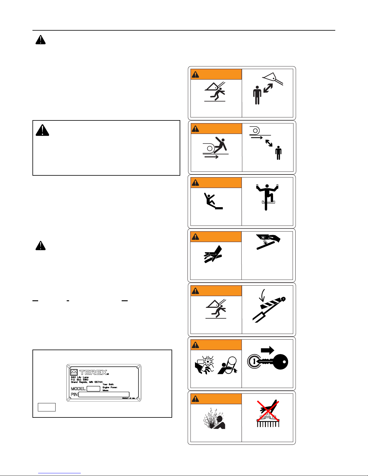
Safety Label Examples
Examples of the labels and decals displayed on the
machine are shown on this page.
1-4
Compact Track Loader
1. Product Safety
1-1
When replacement parts are required for your
machine, use only genuine Terex replacement
parts or parts that meet or exceed original
specifications including, but not limited to physical
dimensions, type, strength and material.
Installing lesser components can lead to premature
failures, product damage, personal injury or death.
WARNING
WARNING
Crush Hazard
Death or serious injury can result
from contact with moving lift arm or
attachment.
WARNING
WARNING
CRUSH HAZARD
Contact with moving machine can
result in death or serious injury.
WARNING
WARNING
Fall Hazard
Serious injury or death can result
from falling.
Keep clear of lift arms and
attachments.
Keep clear of moving machine.
Use the provided access system when
entering or exiting the machine.
2030-593
WARNING
WARNING
Injection Hazard
Escaping fluid under pressure can
penetrate skin, causing serious injury.
WARNING
WARNING
Crush Hazard
Death or serious injury can result
from contact with moving lift arm or
attachment.
WARNING
WARNING
Entanglement Hazard
Rotating parts can cause personal injury.
WARNING
WARNING
• Relieve internal pressure before
disconnecting any line or fitting.
• Keep away from leaks or pinholes.
• Use cardboard to check for leaks.
Fluid injected into skin must be surgically removed within a few hours by a
doctor familiar with this type of injury
or gangrene will result.
Install lift arm brace prior to servicing.
Keep away from fan and belt while the
engine is running. Stop engine before
servicing.
2030-600
Hot fluid under pressure can scald.
Burn Hazard
Allow the machine to cool thoroughly
before opening.
2030-595
1-5
Compact Track Loader
1. Product Safety
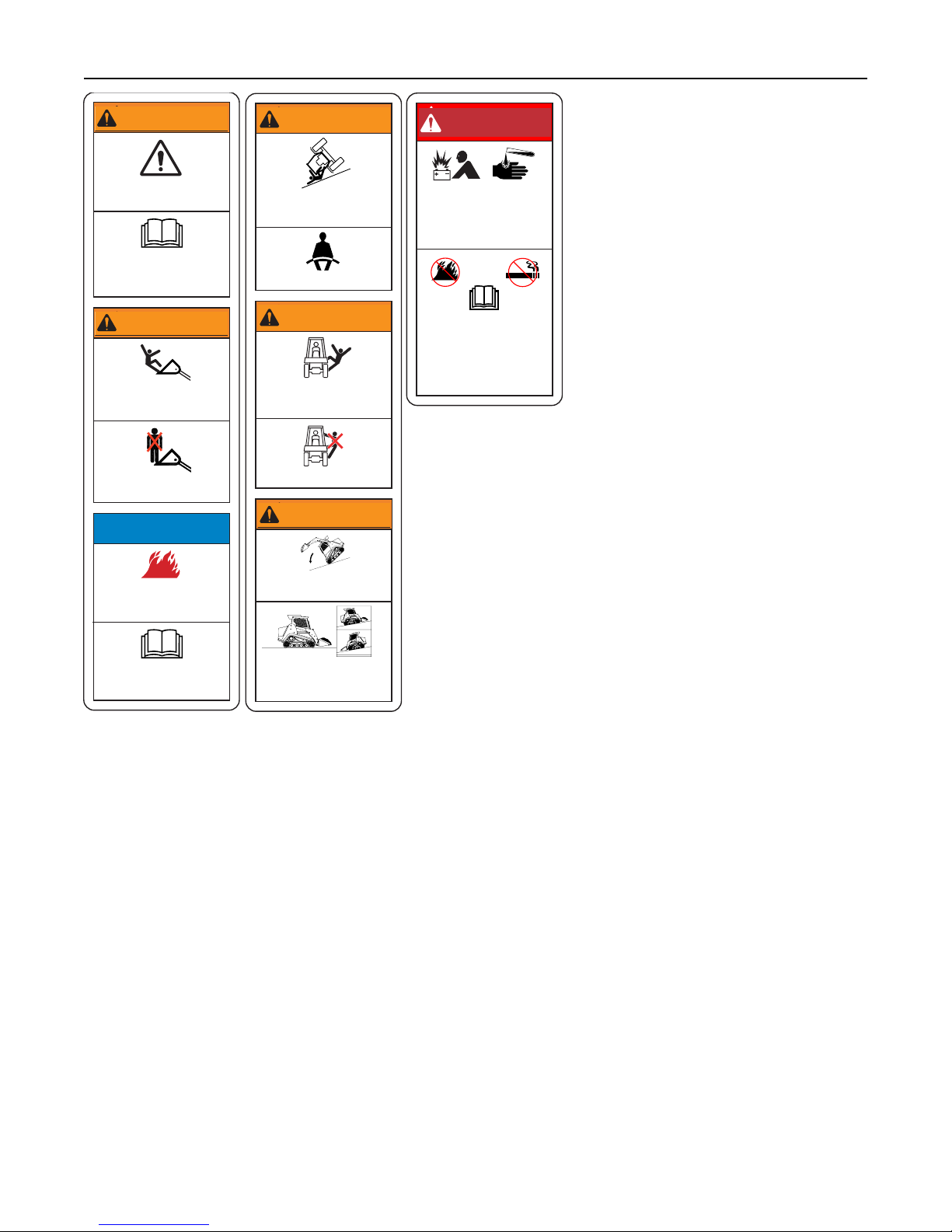
WARNING
WARNING
WARNING
WARNING
DANGER
DANGER
Improper operation or maintenance
can result in serious injury or death.
Read and understand the operator’s manual and all safety signs
prior to operating or maintaining
the machine.
WARNING
WARNING
Fall Hazard
Falling can result in serious injury
or death.
Do not use the bucket/attachment
as a work platform.
NOTICE
Fire Hazard
Flammable debris can collect near
hot components and lead to a fire.
Crush Hazard
Rollover can crush and result in
serious injury or death.
Fasten Seat Belt
WARNING
WARNING
Fall Hazard
Falling from a machine can result
in serious injury or death
No Riders
WARNING
WARNING
Rollover/Ejection Hazard
Serious injury or death can result.
Explosion/Burn Hazard
Will cause death, burns or
blindness due to ignition of
explosive gasses or contact
with corrosive acid.
• Keep all flames/sparks
away!
• No Smoking!
• Read and understand
all manuals prior to
operation.
2030-603
Read Operator’s Manual
Keep the engine, exhaust and
chassis areas free of debris.
Carry loads low. Load unload and
turn on level ground. Travel on
inclines with heaviest end of
machine uphill.


PT-100G Specifications
2. Technical Specifications
& Service Tools
Engine
- Model: Perkins 1104d-44T
- Displacement: 4.4 liter
- Gross horsepower: 99.9 hp (73.5 kW)
- Torque: 310 lb-ft. (420.3 Nm)
- Idle rpm: 1000 (low idle), 2200 (high idle)
- Average water /thermostat temperature: 190°F,
87.8°C
Transmission
- Model: Cat A10VG63 tandem (Rexroth)
Drive Pumps
- Displacement: 3.844 in3/rev (63 cc/rev)
- Relief pressure: 5500 psi (380 bar)
- Flow: 36.6 gpm (138.6 lpm) @ 2200 rpm (per
pump)
Charge Pump
- Displacement @ 1.7:1: 1.49 in3/rev (24.5 cc/rev)
- Relief pressure: 392 +/- 30 psi (27 bar)
- Flow: 14.2 gpm (53.8 lpm) @2200 rpm
Drive Motors
- Model: Bonfiglioli 704 gearbox with KYB MAG 50
VP motor
- Displacement (High): 3.11 in3/rev (50.9 cc/rev)
- Displacement (Low): 1.73 in3/rev (28.4 cc/rev)
- Gear reduction: 18:47:1
Controls (Joysticks)
- Model:
Lift Arm Control Valve
- Make: Rexroth
- Type: Load Sense
Oil Cooler
- Operating pressure: 150 psi (1034 kPa)
- Bypass relief pressure: 80 psi (689 kPa)
- Hot oil sending unit: 225°F (107.2°C)
- Avg. oil operating temp. 50-60°F / 28-33°C above
ambient.
(High flow application 80°F / 44°C above ambient.)
Critical Torque Specs
- Drive Pump Mounting Bolts
-- 200 ft-lb. w/Blue Loctite
- Drive Sprocket Drive Teeth Nuts
-- 41 ft-lb. / 55.6 Nm -Dry
- 10” Idler Wheel Retaining Nut
-- 180 ft-lb. / 244 Nm -w/Red Loctite
- 15” Idler Wheel Retaining Nut
-- 350 ft-lb. / 475 Nm -Dry
- Drive Sprocket Lug Bolts
-- 199 ft-lb. / 270 Nm -Dry
- Drive Motor Mounting Bolts
-- 199 ft-lbs. / 270 Nm -Dry
Service Tools
Listed below are common service tools which are identified and utilized in the service procedures described
in this manual. Use tools recommended by Terex
whenever possible to reduce risk of injury and or
machine damage during service.
Auxiliary Pump
- Model: A10VO85 (Rexroth)
- Type: Axial Piston, Variable Load Sense
- Displacement: 5.19 in3/rev (85 cc/rev)
- Low Flow: 0-20 gpm (0-75.7 lpm) @ 2200 rpm
- High Flow: 30-43 gpm (114-163 lpm) @ 2200 rpm
- Low Flow Relief Pressure: 3300 psi (22,750 kPa)
- High Flow Relief Pressure: 3800 psi (26,200 kPa)
- LS (Standby) Pressure: 218 psi (1,503 kPa)
- Cooling/filtering: Oil is filtered and cooled at all
times. In auxiliary mode, the oil is filtered after the
attachment to protect the machine if the attachment motor fails or contaminants are introduced
from the quick couplers.
• Heavy Duty Hydraulic Jack (5-ton rating)
• Test Gauge Kit (TEREX P/N: 0402-935)
• Ratchet Strap
• Long Pry Bar(s)
2-1

Chapter Overview
This chapter contains diagrams for the following PT100G circuits: hydraulic charge circuit, hydraulic auxiliary circuit, hydraulic control circuit, hydraulic drive circuit, lift arm control valve, hydraulic solenoid blocks
and electrical attachment outlet.
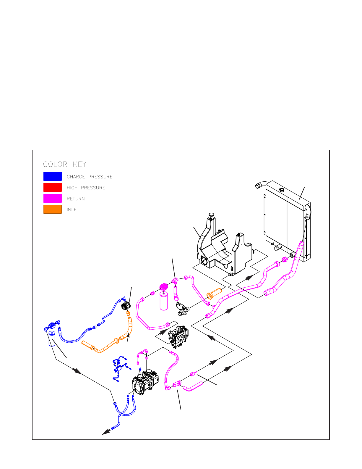
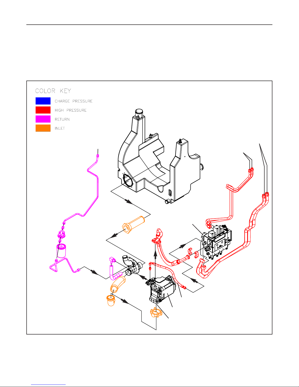
Figure 3-1 PT-100G Hydraulic Charge Circuit
Hydraulic Charge Circuit
3. Circuit Diagrams
3-1
OIL COOLER
INLET
CHARGE PUMP
TANK
5 MICRON FILTER
CHECK VALVE
(15 PSI / 103 kPa)
CHECK VALVE
(0 PSI / 0 kPa)
CHECK VALVE
(80 PSI / 552 kPa)
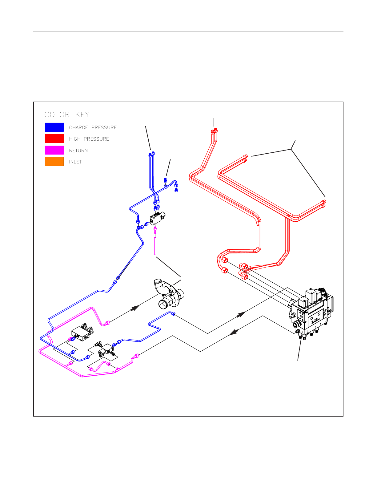
Hydraulic Auxiliary Circuit
Figure 3-2 PT-100G Hydraulic Auxiliary Circuit
3-2
Compact Track Loader
3. Circuit Diagrams
TO HIGH FLOW AUX. Q/C
AUXILIARY PUMP
LIFT ARM VALVE
AUXILIARY PUMP INLET
TO LOW FLOW AUX. Q/C
FROM ATTACHMENT
CASE DRAIN Q/C
LOAD SENSE
Hydraulic Control Circuit
Figure 3-3 PT-100G Hydraulic Control Circuit
3-3
Compact Track Loader
3. Circuit Diagrams
LIFT ARM CONTROL VALVE
TO LIFT ARM CYL.
TO BUCKET CYL.
TO POWER Q/A.
TO
TANK
CHARGE PRESSURE
TEST PORT
(400 / 2758 kPa)
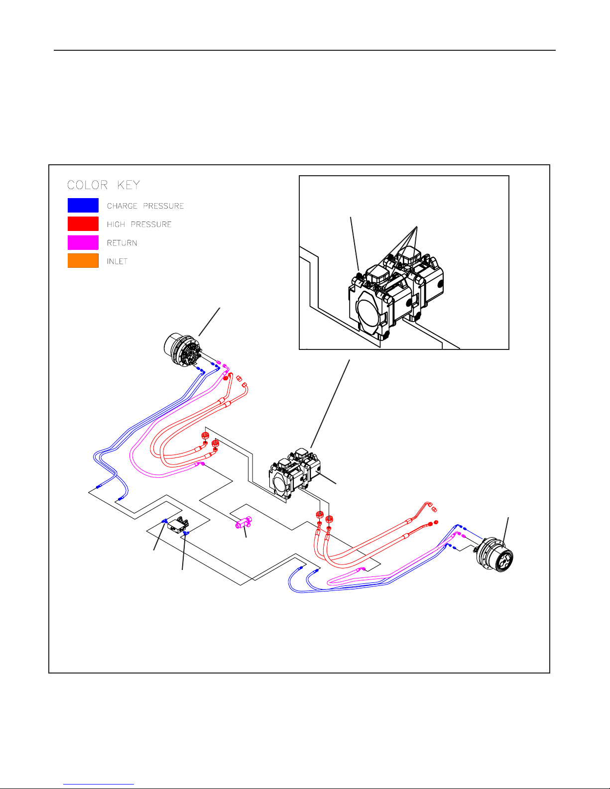
Hydraulic Drive Circuit
Figure 3-4 PT-100G Hydraulic Drive Circuit
3-4
Compact Track Loader
3. Circuit Diagrams
DRIVE MOTOR
DRIVE PUMP
CASE DRAIN
(TO COOLER)
BRAKE
2-SPEED SHIFT
DRIVE MOTOR
CHARGE PRESSURE
RELIEF
(400 / 2758 kPa)
DRIVE PRESSURE
RELIEF VALVES (4)
(5500 PSI / 37920 kPa)
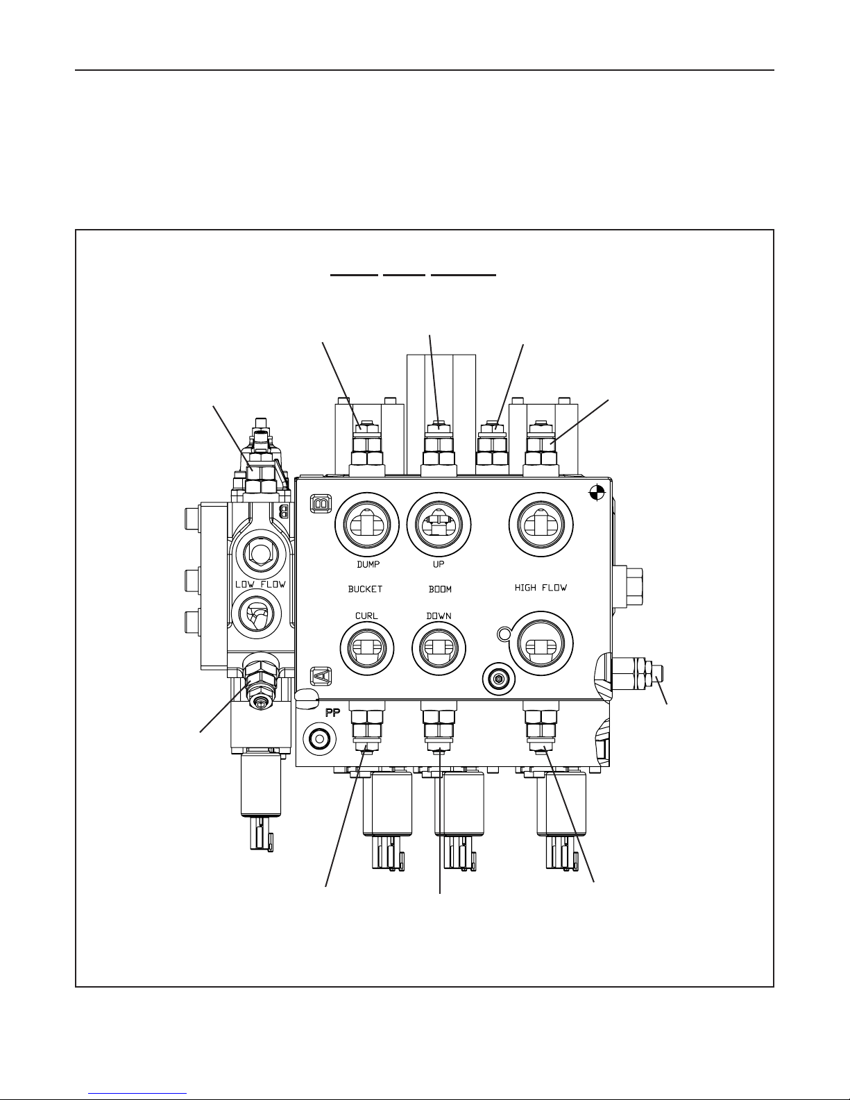
Lift Arm Control Valve
Figure 3-5 PT-100G Lift Arm Control Valve
3-5
Compact Track Loader
3. Circuit Diagrams
RELIEF VALVE SETTINGS
3989 PSI
(27500 kPa)
3989 PSI
(27500 kPa)
4206 PSI
(29000 kPa)
3481 PSI
(24000 kPa)
3989 PSI
(27500 kPa)
4496 PSI
(31000 kPa)
3989 PSI
(27500 kPa)
3307 PSI
(22800 kPa)
4496 PSI
(31000 kPa)
3989 PSI
(27500 kPa)
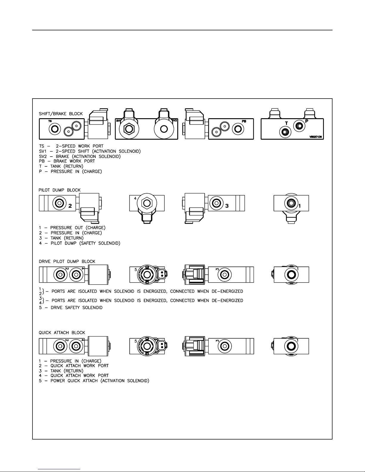
Hydraulic Solenoid Blocks
Figure 3-6 PT-100G Hyd. Solenoid blocks
3-6
Compact Track Loader
3. Circuit Diagrams
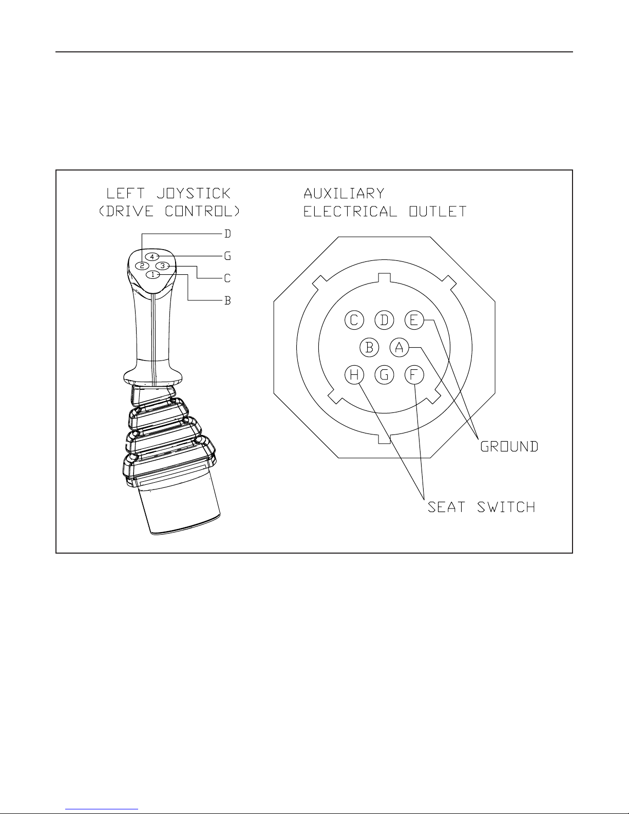
Electrical Attachment Outlet
Figure 3-7 PT-100G Electrical Attachment Outlet
3-7
Compact Track Loader
3. Circuit Diagrams

Chapter Overview
This chapter provides information on general
maintenance procedures for the PT-100G. If there is an
issue that requires troubleshooting, refer to Chapter
18, Troubleshooting.
Personal Safety
Improper or incomplete maintenance/repair of a
Compact Track Loader can be dangerous and may result
in machine damage, injury or even death.
Do not attempt to perform any type of repair or
maintenance on a Compact Track Loader until you have
read and fully understood the information in this
manual.
Refer to the Operation and Maintenance manual for
instructions regarding proper machine operation
techniques before operating any Compact Track Loader.
Prior to performing any type of service work on a
Compact Track Loader, read and understand Chapter
1 (Product Safety) for personal safety information.
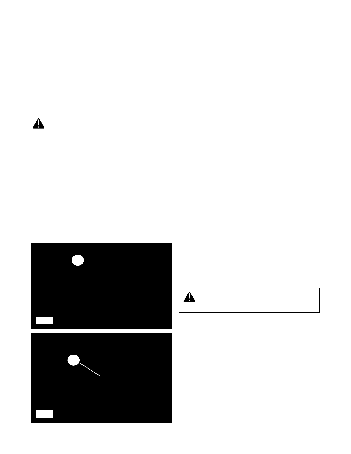
Lift Arm Brace
The lift arm brace (fig. 4-1, item A) is intended to keep
service personnel safe when it is necessary to work on
a machine with the lift arms in the raised position. It is
not safe to rely on the hydraulic system to hold the lift
arms in the raised position just as it is not safe to crawl
under a machine supported only by a jack. The lift arm
brace is used to support the weight of the lift arms
much like jack stands are used to mechanically
support vehicle weight.
To install the lift arm brace:
1. Park the machine on level ground in a safe area
for performing service work.
2. Remove any attachments that may be fastened to
the quick attach.
3. Have an assistant remove the retaining pins (fig.
4-2, item B)securing the lift arm brace and remove
it from the machine.
4. Make sure bystanders are clear of the lift arms,
then raise them to the upper limit.
5. Have an assistant install the brace around the
cylinder shaft as shown and reinstall the pins to
secure it to the cylinder.
6. Lower the lift arms slowly until they come to rest
on the brace.
7. It is now safe to shut the engine off and exit the
machine.
To remove the lift arm brace:
1. Start the machine and raise the lift arms until they
are clear of the brace.
2. Once clear, have an assistant remove the brace
from the cylinder and stow it on the machine with
the pins.
3. Once the brace has been stowed and the assistant
is clear of the lift arms, lower the arms to the
ground and shut the engine off to complete the
procedure.
A
4-1
4-2
Do not work on or near the machine with the
lift arms in the raised position unless the lift
arm brace has been correctly installed.
4-1
4. Maintenance
B
Compact Track Loader
4. Maintenance
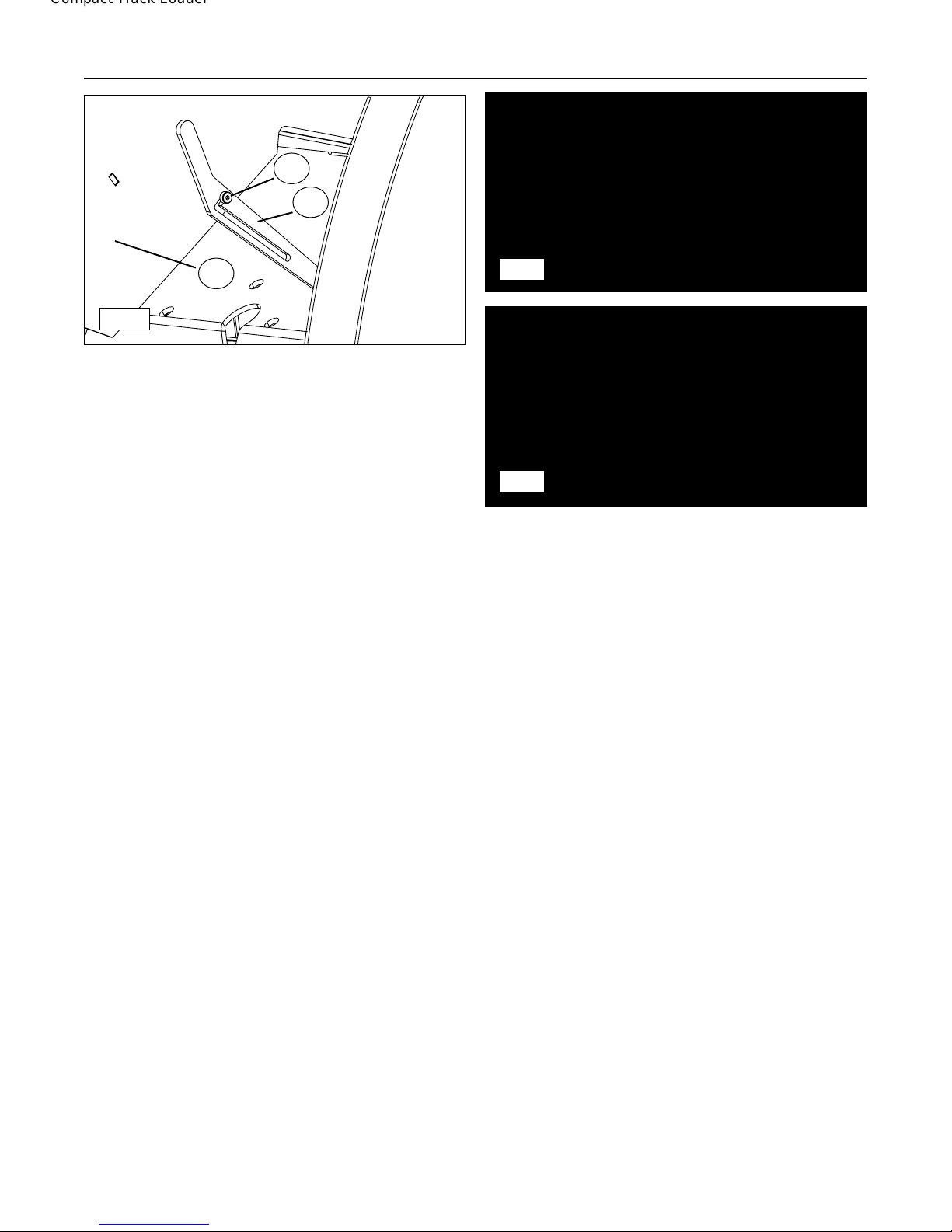
C
B
A
4-3
Tilt-Up Cab
The ROPS/FOPS approved cab (fig. 4-3, item A) tilts
up to allow easy access to components while
performing maintenance or service. It is equipped with
a gas spring assist and a brace mechanism to hold it
in place while tilted.
To tilt the cab:
1. Remove any attachments that may be fastened to
the machine.
2. (Optional) Raise the lift arms and secure them
with the lift arm brace. (See page 4-1)
3. Remove the two bolts (four for forestry) that
fasten the cab to the footwell. They are located
along the upper edge of the footwell inside the
cab, one in each of the front corners (rear as well
on forestry machines).
4. Once the bolts have been removed, tilt the cab
slowly upwards. The cab brace (fig. 4-3, item B)
should fall onto the shoulder bolt (fig. 4-3, item C)
locking the cab in its upright position.
The cab is now secure.
To lower the cab:
1. Raise the cab brace so that the locking channel is
clear of the shoulder bolt.
2. Hold the brace upwards and lower the cab until
the locking channel is clear of the shoulder bolt
then release the brace.
3. The cab is now free to be lowered into operating
position.
4. Lower the cab completely and then fasten it to the
footwell with the bolts removed previously.
5. Reinstall the pre-cleaner.
6. Lower the lift arms (if raised) per page 4-1.
4-4
4-5
Jacking Procedure
Occasionally, your machine may need to be
suspended off of the ground to perform maintenance.
Exercise caution when jacking the machine. Always
use a jack that is capable of lifting the machine and
support its weight with Terex approved jack stands
while suspended. Never work on or under a machine
supported only by a jack.
To safely jack your machine:
1. Remove any attachments that may be fastened to
the machine and raise the lift arms.
2. Install the lift arm brace as instructed on page 4-1.
3. Once the lift arms are secured, carefully exit the
machine.
4. Roll or slide your jack under the front of the
machine and center the lifting pad directly under
the middle of the front torsion axle.
5. Once in place, jack the machine upward making
sure it remains stable until it has reached sufficient
height to install a Terex jack stand beneath the
machine. (fig. 4-4)
6. Slide the jack stand into place making sure it is
centered under the machine (left to right when
viewed from the front) and far enough back for the
machine to remain stable when the jack is lowered
and the front of the machine rests on the stand.
(fig. 4-5)
7. Once the stand is in place, slowly lower the
machine onto the stand and then remove the jack.
Repeat steps 4-7 at the rear of the machine should
both ends of the machine need to be off of the ground
for service.
4-2
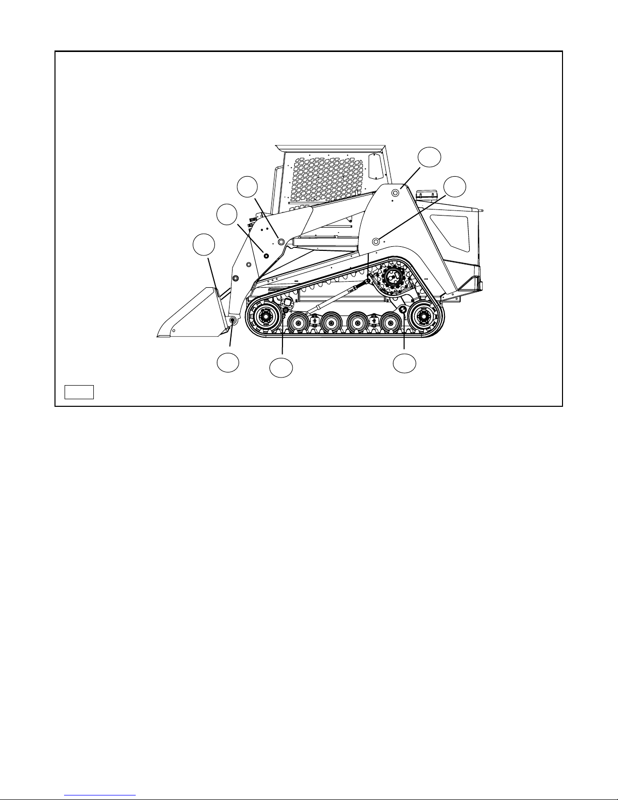
Grease Fitting Locations
A. Lower Bucket Cylinder Pivot
B. Upper Bucket Cylinder Pivot
C. Front Lift Cylinder Pivot
D. Lift Arm Pivot
E. Rear Lift Cylinder Pivot
F. Rear Axle Pivot (2)
G. Front Axle Pivot (2)
H. Lower Bucket Pivot
G
F
D
E
H
A
B
C
4-6
Compact Track Loader
4. Maintenance
4-3
Grease Fittings
The PT 100G is equipped with grease fittings at pivot points throughout the machine. The illustration above
shows the locations of all fittings on the left side of the machine. An identical fitting exists on the right side of the
machine for each one identified in the illustration. Lubricate all fittings DAILY or after every 10 hours of operation
to maximize component life and ensure proper machine function. (fig. 4-6)
Undercarriages
The undercarriage assemblies in Compact Track Loaders typically operate in harsh working conditions. They
work in mud, gravel, debris and various other abrasive materials during operation. Terex recommends a daily
inspection of the undercarriage assemblies and cleaning if necessary.
Materials that are particularly sticky or abrasive like clay, mud, or gravel should be cleaned from the
undercarriages more often to minimize component wear. A pressure washer works well for cleaning materials
from the undercarriages. At times when a pressure washer is not available, use a bar, shovel or similar device to
remove foreign materials.
When cleaning, pay particular attention to the drive tables, sprockets, and the front and rear wheels where debris
is likely to accumulate. If working in scrap or debris, inspect more often and remove foreign objects that may
wrap around or lodge themselves between components causing premature wear and damage.
Operation in loamy sand or on turf or other finished surfaces may require less frequent cleaning, but daily
inspection is still advised.
Compact Track Loader
4. Maintenance
Track Tension (PT-100G)
Proper track tension must be maintained for optimal
performance and track/undercarriage life. Running a
track that is too loose may cause the track to misfeed
possibly causing damage to the track and or
undercarriage components. Running a track that is too
tight may cause the track to stretch, create premature
bearing failure, or other preventable damage to the
machine. As a rule, a track should only be tightened to
the point where there is no visible sag. Never tighten
your tracks beyond this point.
Note: During the first 50 hours of operation the tracks
will "break-in" and will most likely require adjustment.
To check track tension: (fig. 4-7, 4-8)
1. Drive the machine forward 5 feet to remove belt
slack from the lower and rearward portions of the
track.
2. Lay a straight edge along the top of the track
bridging the drive sprocket and front idler wheel.
3. Apply 90 lbs. of down force to the the track by
either placing weight on top, or by hanging the
weight by using rope or wire, midway between
the drive sprocket and front idler as seen in
figure 4-8.
4. Measure from the bottom of the straight edge to
the lug surface (top) of the track. The deflection
should measure between 3/4" and 1" (1.9-2.5
cm).
Straight-Edge
4-7
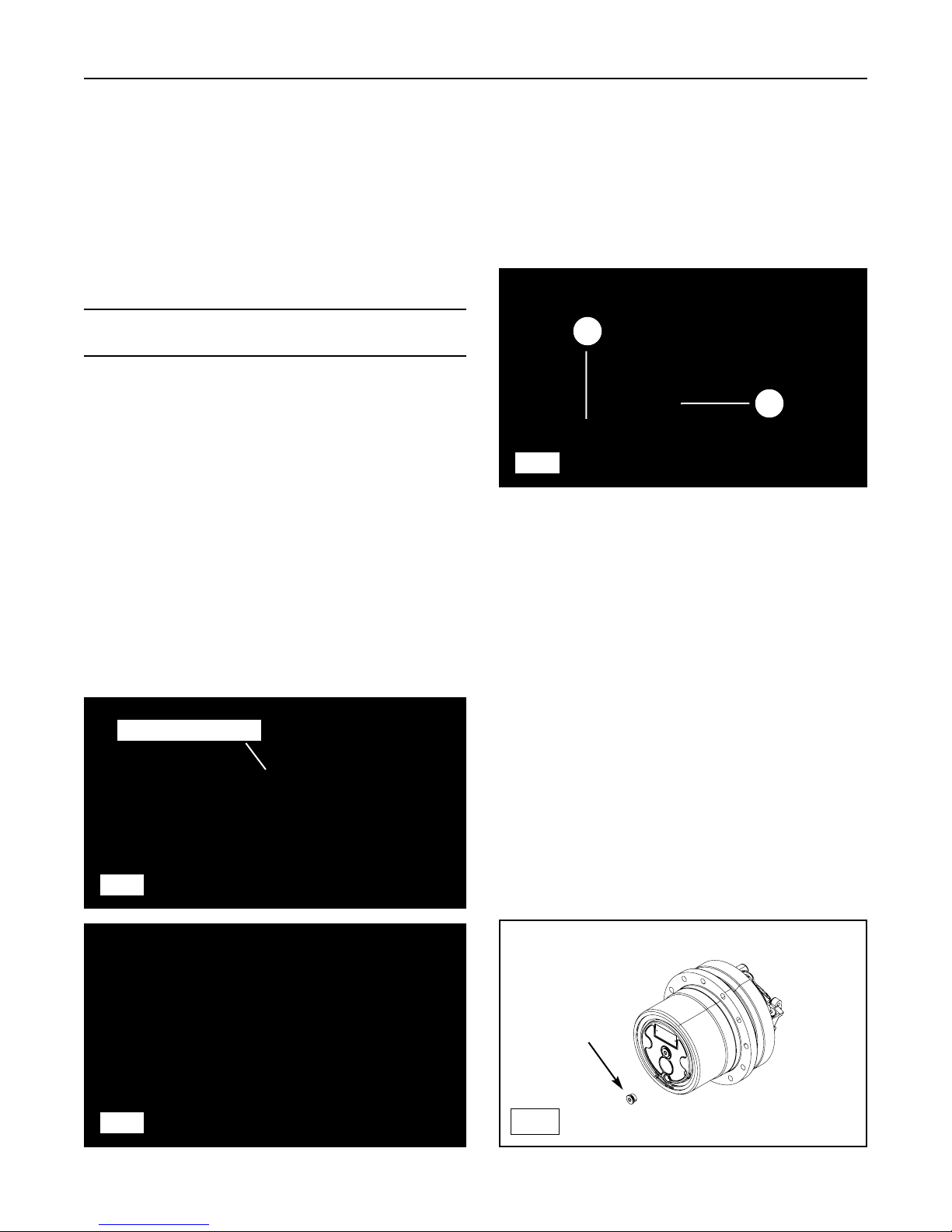
To adjust track tension: (fig. 4-9)
1. Loosen the lock nut (A) on the turnbuckle (B)
and adjust by turning the turn buckle itself until
proper tension has been achieved.
2. Then tighten the turnbuckle lock nut to complete
the procedure.
3. Repeat the adjustment procedure on the other
side of the machine if necessary.
B
A
4-9
Planetary Oil Change (fig. 4-10)
1. Place the machine on jackstands as described in
jacking prodedure in this chapter.
2. Orient the perimeter drain plug at the very
bottom of the drive motor, then turn the engine
off and remove the key to avoid accidental start.
3. Remove the plug and drain the oil into a suitable
catch container. (fig. 4-10) Dispose oil according
to mandates.
4. Start the machine (make sure all personnel are
clear of the machine), then roll the drive motor
over so that the drain/fill hole is on the very top
of the drive motor. Stop the engine and remove
the key to avoid accidental start.
5. Fill the planetary with .95qt (.9l) of 75-140
synthetic gear oil, reinstall plug.
6. Repeat the procedure on the opposite drive
motor.
4-8
drain
plug
4-10
4-4
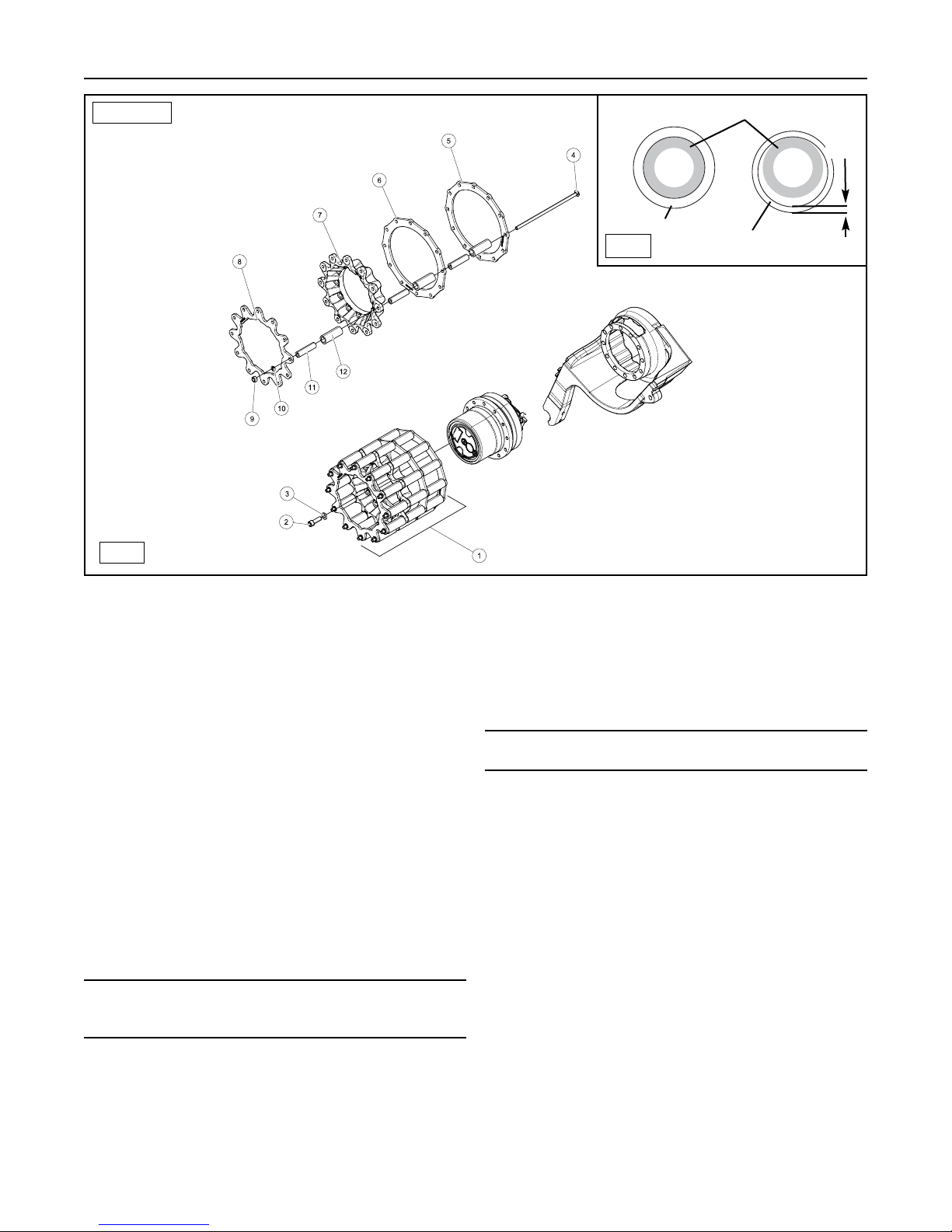
Drive Sprocket Rollers
Terex compact track loaders utilize rollers on the drive
sprockets to drive the track. These rollers help
minimize friction between the track and the drive
sprocket to prolong track life.
The rollers rotate around hardened steel pins and
usually wear on their inside surfaces. As they wear, the
rollers become thinner, but will continue to function as
long as they rotate freely around the pins. Sprocket
rollers should be inspected every 50 hours of operation
and replaced if cracked or worn to less than 35% of
original thickness. (.088” / .22cm)
To replace worn rollers: (fig. 4-11)
1. Begin by performing steps 1-4 in the track removal
procedure on page 4-6 to allow the sprocket to be
removed.
2. Remove the sprocket mounting bolts (2) to release
sprocket from drive motor; then remove the
sprocket.
Note: You may need to pry or lift the track upwards
with a hoist above the drive sprocket to provide
clearance for removal.
3. Remove one bolt (4) holding the steel pins (11)
and rollers (12) in place.
4. Install the new rollers over the pins, then slide the
bolt back through the sprocket and pins and
secure it with the nut (9).
5. Repeat this process as required throughout the
sprocket.
6. Reinstall the sprocket by reversing steps 2-3.
7. Repeat steps 1-5 on the other side of the machine
if necessary.
8. Perform the track tension adjustment and check
procedures on page 4-4.
Note: Replace rollers as a set to simplify inspection
and maintain proper sprocket function.
4-5
Compact Track Loader
4. Maintenance
New Roller
Normal Wear
50% life
Steel Pin
(.088”)
PT-100G
4-11
4-11a
Track Removal/Installation
Tracks may need to be removed periodically to inspect
undercarriage components or for replacement if worn
or damaged. This section covers the procedure to
remove and install a track on PT 100G machines.
Tools required:
• Socket/impact wrench
• Ratchet strap
• Heavy duty hydraulic jack
• Combination wrench
• Long pry bar(s)
• Terex approved jack stands (2)
• Spray lubricant
• Shop vac or pressure washer
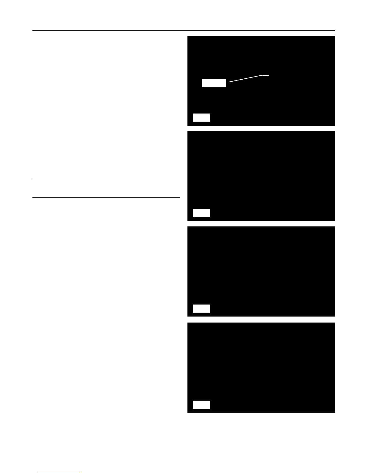
Track Removal
1. Break up and remove any foreign material from the
cavity between the suspension rail and the drive
table support (fig. 4-12).
Note: A shop vac or pressure washer will work well to
remove material from this cavity.
2. Clean the threads on the turnbuckle thoroughly
using a stiff bristle brush.
3. Loosen the lock nut on the turnbuckle and spin it
to the end of the threaded shaft to allow clearance
when the drive table is lowered (fig. 4-13).
4. Rotate the turnbuckle and lower the drive table as
far as it will go (fig. 4-14).
5. Remove the bolts securing the outer front wheel to
the hub. Then remove the wheel (fig. 4-15, 4-16).
4-6
Compact Track Loader
4. Maintenance
4-12
4-13
4-14
Cavity
4-15

6. Remove the outer scraper plate from the
suspension rail. (fig. 4-17)
7. Remove the bolts securing the inner wheel to the
hub, then remove the wheel.
(fig. 4-18, 4-19)
8. Use a pry bar to peel the track over the inner
wheel(s) toward the outside of the machine.
(fig. 4-20)
9. Once the track is off of the front wheel(s), pull the
rear of the track clear of the suspension.
(fig. 4-21, 4-22)
4-7
Compact Track Loader
4. Maintenance
4-16
4-17
4-18
4-19
4-20
4-21
4-22

Track Installation
1. Slide the track over the drive sprocket at the rear
of the machine (fig. 4-23, 4-24).
2. Slide the front of the track into position for
installation (fig. 4-25).
3. Lubricate the inner front wheel and the inside of
the front portion of the track with a spray lubricant
(fig. 4-26).
4. Attach a ratchet strap to the upper front portion of
the track and the other end to one of the tow
hooks on the front of the machine (fig. 4-27).
5. Tighten the strap until the track is pulled upward
slightly and in position to slide over the inner idler
wheel at the front (fig. 4-27).
6. Pull all of the slack forward and make sure the
track drive lugs are properly meshed with the
sprocket to provide as much slack as possible for
installation.
7. If you have an assistant, have them pull the track
forward while you push inward on the track. Work
the track over the wheel and into place.
8. If you do not have an assistant, push the track
forward and inward in a quick forceful motion to
slide the track into place. The ratchet strap will
help to keep the track in place while you work it
over the idler (fig. 4-28).
4-8
Compact Track Loader
4. Maintenance
4-25
4-26
4-27
4-23
4-24
4-28
 Loading...