

Page 1
CLICK HERE FOR
TABLE OF
CONTENTS
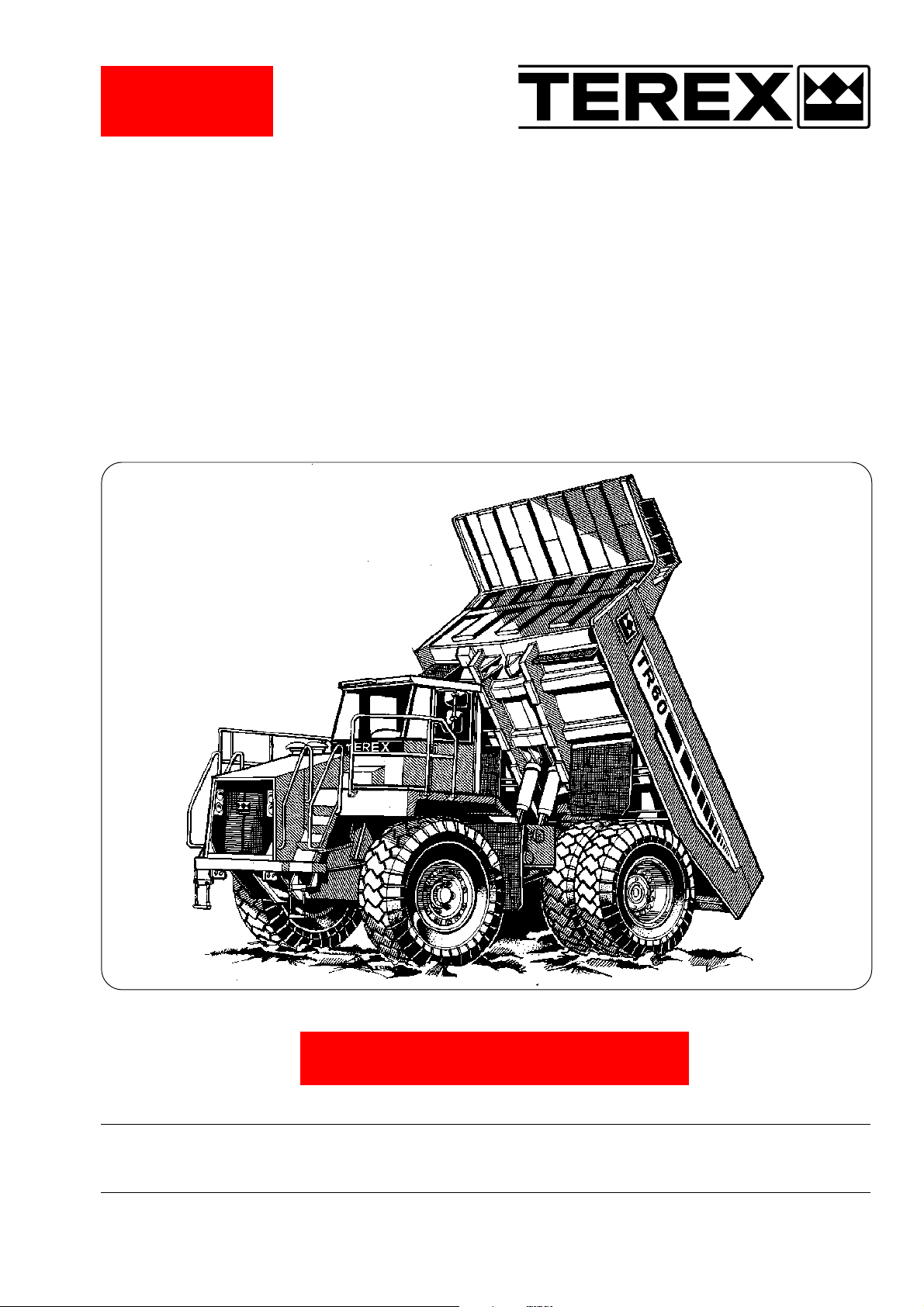
TR60
Off-Highway Truck
Maintenance Manual
SM 1564 Rev 3 02-02
CLICK HERE TO RETURN TO
MAIN LIBRARY INDEX
TECHNICAL PUBLICATIONS DEPARTMENT
TEREX EQUIPMENT LIMITED,
MOTHERWELL, SCOTLAND, ML1 5RY
REF. NO. SM750/782
Page 2

Page 3
Service
The information contained within this
Alert must not be made available to
third parties not authorised to receive it.
Information
Alert
DATE: April 1994 B168
MODEL: General
SUBJECT: VITON 'O' RINGS AND SEALS (FLUORO-ELASTOMERS) - SAFETY HAZARDS
PURPOSE:
To advise potentially hazardous condition.
DETAIL:
It has been brought to our attention that 'Viton' material used in manufacture of oil seals and 'O' rings, produces
a highly corrosive acid (Hydrofluoric) when subjected to temperatures above 315° C.
The resulting contamination can have extreme consequences on human tissue since it is almost impossible to
remove after contact.
We therefore recommend the following procedure when it is necessary to inspect any equipment that has been
subjected to a high temperature i.e. fire.
a. Visually inspect for any gaskets or seals which have suffered from heat; they will appear black and sticky.
b. If this is affirmed - Do Not Touch
c. Make enquiries to ascertain the material composition. Any Fluoro-elastomer (Viton, Fluorel or Tecmoflon)
should be considered dangerous but natural rubber and nitrile are non-hazardous.
d. If Fluoro-elastomer seals have been used, then the affected area MUST be decontaminated before
undertaking further work.
e. Disposable Heavy Duty Gloves (Neoprene) MUST be worn and the affected area decontaminated by
washing thoroughly with Limewater (Calcium Hydroxide solution).
f. Any cloths, residue and gloves used MUST be safely discarded after use.
Note: Burning of the discarded items is NOT RECOMMENDED, except in an approved incineration process
where the gaseous products are treated by alkaline scrubbing.
TEREX SERVICE DEPARTMENT
TEREX Equipment Limited, Motherwell, Scotland ML1 5RY Tel. (0698) 732121 Tlx. 77141 Fax. (0698) 734046
TEREX Division, Tulsa, Oklahoma, 74107 USA Tel. (918) 446-5581 Fax. (918) 446-9752
Page 4

THIS PAGE IS INTENTIONALLY LEFT BLANK
Page 5
IMPORTANT SAFETY NOTICE
Proper service and repair is important to the safe, reliable operation of all motor vehicles. The service
procedures recommended and described in this publication, are effective methods for performing service
operations. Some of these service operations require the use of tools specially designed for the purpose.
The special tools should be used when, and as recommended.
It is important to note that this publication contains various WARNINGS and NOTES which should be
carefully read in order to minimize the risk of personal injury to personnel, or the possibility that improper
service methods will be followed which may damage the vehicle or render it unsafe. It is also important to
understand these WARNINGS and NOTES are not exhaustive. It is not possible to know, evaluate and
advise the service trade of ALL conceivable ways in which service might be carried out, or, of the
possible hazardous consequences of each way. Consequently, no such broad evaluation has been
undertaken. Accordingly, anyone who uses a service procedure, or tool, which is not recommended, must
first satisfy themselves thoroughly that neither their safety, nor vehicle safety, will be jeopardized by the
service method he/she selects.
Two types of heading are used in this manual to attract your attention.
1. WARNING - This symbol is used when an operating procedure, practice, etc., which, if not correctly
followed could result in personal injury or loss of life. Look for this symbol to point out important safety
precautions. It means - ATTENTION! BECOME ALERT! YOUR SAFETY IS INVOLVED!
2. Note - This is used when an operating procedure, practice, etc., which, if not strictly observed, could result in
damage to or destruction of equipment.
WARNING
Never use parts which are altered, modified, or weakened in operation. This can seriously
jeopardize the integrity of the machine and could result in property damage or serious personal
injury.
SM 222 Rev 1 9-93
Page 6

THIS PAGE IS INTENTIONALLY LEFT BLANK
Page 7
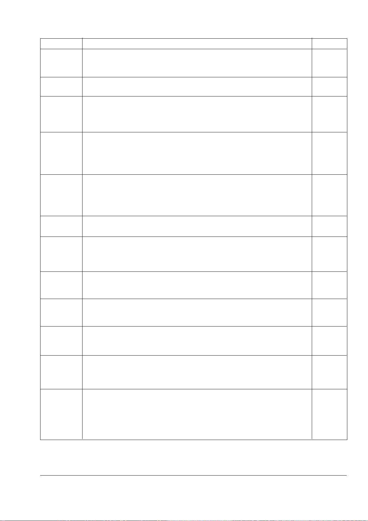
TABLE OF CONTENTS
Section No. Description SM No.
000 GENERAL INFORMATION
0000 TR60 Off-Highway Truck 1566
0010 Welding Procedure 2172
100 CHASSIS
0010 Chassis, Hood and Fenders 1570
110 ENGINE
0030 Engine and Mounting 1571
0050 Air Cleaner 1572
0130 Power Takeoff 1573
120 TRANSMISSION
0010 Transmission and Mounting 1574
0070 Commercial Electronic Control (CEC) Shift System 1575
0090 Power Takeoff 1178
0100 Transmission Oil Filter 1576
13 0 DRIVELINE
0010 Front Driveline - Pre June 1998 Production 1180
0010 Front Driveline - From June 1998 Production 1577
0020 Rear Driveline - Pre June 1998 Production 1181
0020 Rear Driveline - From June 1998 Production 1578
14 0 FRONT AXLE
0040 Wheel, Rim and Tyre 1579
16 0 REAR AXLE
0020 Differential 1580
0030 Axle Group 1184
0050 Wheel, Rim and Tyre 1582
165 BRAKE PARTS
0020 Brake Parts - Front Axle 1186
` 0030 Brake Parts - Rear Axle 1583
18 0 SUSPENSION SYSTEM
0030 Ride Cylinder - Front 1584
0050 Ride Cylinder - Rear 1189
190 CIRCUIT DIAGRAMS
0000 Circuit Diagrams 1585
0270 Switches and Sensors 1586
200 FUEL SYSTEM
0010 Fuel Tank and Mounting 1587
0040 Fuel Lines 1195
0051 Electronic Foot Pedal 1196
21 0 COOLING SYSTEM
0000 Cooling System 1197
0040 Radiator, Header Tank and Mounting 1588
0050 Disc Brake Oil Cooler 1589
0060 Transmission Oil Cooler 1590
SM 1565 12-98
1
Page 8
TABLE OF CONTENTS
Section No. Description SM No.
22 0 STEERING SYSTEM
0000 Steering System Schematic 1591
0040 Steering and Brake Control Tank 1592
0050 Steering Pump 1204
0080 Accumulator 1205
0090 Steering Valve 1206 Rev 1
0110 Double Relief Valve 1208
0120 Steering Cylinder and Linkage - Pre October 1999 Production 1207 Rev 1
0120 Steering Cylinder and Linkage - From October 1999 Production 1908
0130 Accumulator Valve 1209
0150 Steering Filter 1593
23 0 BODY SYSTEM
0000 Body System Schematic 1594 Rev 2
0040 Body and Disc Brake Cooling Tank 1595
0050 Tandem Pump 1213
0060 Body Control Valve 1596 Rev 1
0081 Body Control Joystick 1597
0090 Kick-over Valve 1218
0120 Relief Valve 1598
0121 Pilot Supply Valve 1599
0130 Body Cylinder 1221
25 0 BRAKING SYSTEM
0000 Braking System Schematic 1222 Rev 1
0050 Brake Manifold Valve 1223
0060 Accumulator 1600
0070 Treadle Valve 1225 Rev 1
0090 Directional Control Valve 1226
0100 Monoblock Brake Valve 1227 Rev 2
0110 Pressure Reducing Valve (Optional) 1820
0130 Retarder Control Valve 1601 Rev 1
0140 Shuttle Valve 1229
260 OPERATORS COMPARTMENT
0010 Cab and Mounting 1602 Rev 1
0090 Driver Seat and Mounting 1901
0110 Passenger Seat and Mounting - Pre January 2000 Production 1603
0110 Passenger Seat and Mounting - From January 2000 Production 1902
0130 Air Conditioning and Mounting 1620 Rev 1
270 BODY
0010 Body and Mounting 1604
300 MISCELLANEOUS
0020 Lubrication System 1605 Rev 1
0070 Service Tools 1237 Rev 1
0080 Standard Bolt and Nut Torque Specifications 1238
0090 Unit Storage 1239
* * * *
2
SM 1565 Rev 3 02-02
Page 9
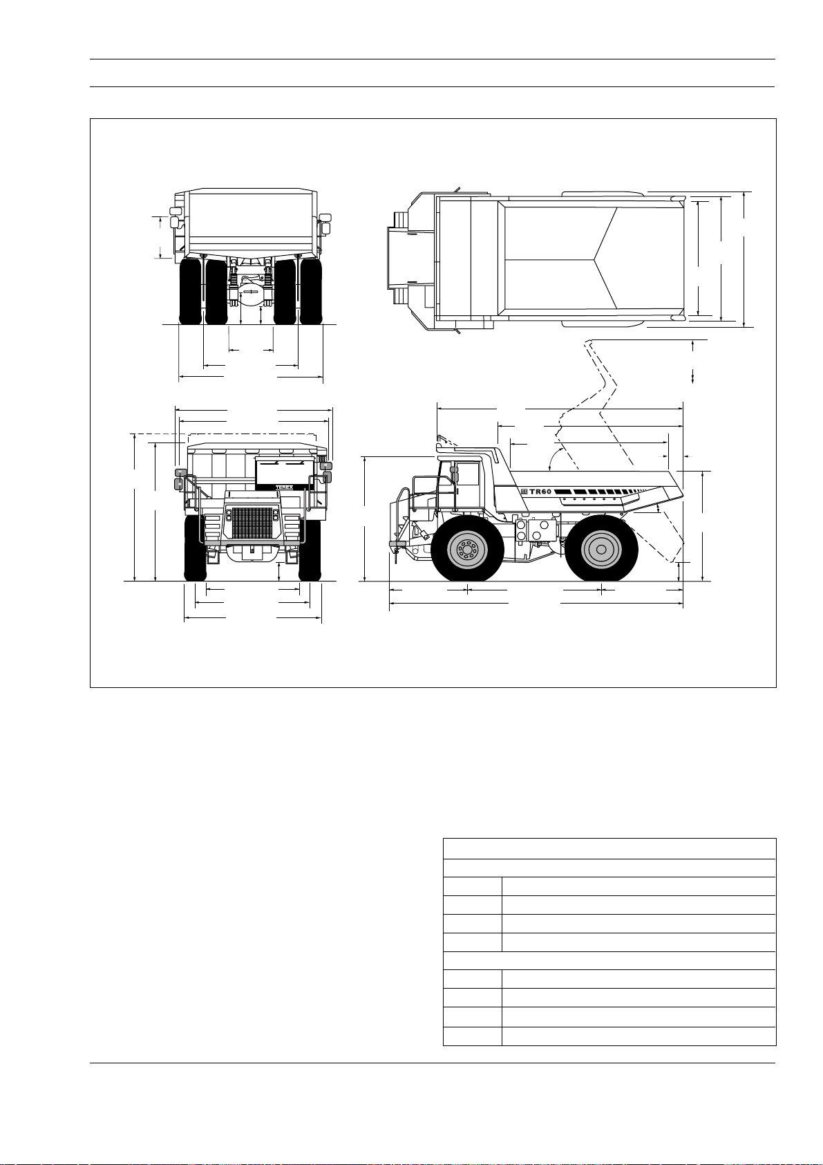
GENERAL INFORMATION - TR60 Off-Highway Truck
Section 000-0000
SM - 1957
Max
Body
Depth
Optional
Spillguard
4 820
(15-10)
1 425
(4-8)
4 440
(14-7)
600
950
(2-0)
(3-1)
1 380
(4-6)
2 900 (9-6)
4 450 (14-7)
4 980 (16-4)
4 630 (15-2)
660
(2-2)
2 580 (8-5)
3 320 (10-11)
4 060 (13-4)
Vehicle Clearance Diameter (SAE) 21 m (68-10)
3 970
(13-0)
2 360 (7-9)
7 750
(25-5)
6 000
(19-8)
4 170 (13-8)
9 130 (29-11)
5 050
(16-7)
58˚
15˚
580 (1-11)
2 600 (8-6)
4 470
(14-8)
4 270
(14-0)
3 950
(12-11)
8 050
(26-5)
500
(1-8)
3 680
(12-1)
Dimensions in mm (ft-in)
Fig. 1 - Machine Dimensions
ENGINE
Make/Model .................................... Cummins QSK19-C650
Type .................... 4 Cycle, Turbocharged/Low Temperature
Aftercooled. Electronic Management
Gross Power 1 500 through 2 100 rev/min...............485 kW
(650 hp, 659 PS)
Net Power 1 500 through 2 100 rev/min .................. 462 kW
(620 hp, 628 PS)
Note: Power ratings to SAE J1995 Jun 95. Engine
emission meets USA EPA/CARB MOH 40 CFR 89 and
EU NRMM (non-road mobile machinery directive).
Maximum Torque .............................. 3 084 Nm (2 275 lbf ft)
at 1 300 through 1 500 rev/min
Number of Cylinders/Configuration .........................6, in line
Bore x Stroke ........................ 159 x 159 mm (6.25 x 6.25 in)
Total Displacement .............................. 18.9 litres (1 150 in³)
Starting...................................................................... Electric
Maximum Speed, Full Load ............................ 2 100 rev/min
Maximum Speed, No Load ............................. 2 350 rev/min
Idle Speed.......................................................Self Adjusting
Safe Operating Angle .................................. 30°/60% Grade
SM 1566 12-98
TRANSMISSION
Make/Model .............................................. Allison M6600AR
automatic electronic control with soft shift feature.
Remote mounted in the frame. Integral TC 682 torque
converter and planetary gearing. Six speeds forward, two
reverse. Automatic converter lockup action in all speed
ranges. With body up, gear range is limited to 1st forward
only. Downshift inhibitor. Intregal hydraulic retarder.
Speeds With 24.00 R 35 Tyres
Forward
Gear 1 2 3 4 5 6
Ratio 4.00 2.68 2.01 1.35 1.00 0.67
km/h 9.5 14.2 18.9 28.2 38.1 57.0
mile/h 5.9 8.8 11.8 17.5 23.7 35.5
Reverse
Gear 1 2
Ratio 5.12 3.46
km/h 7.4 11.0
mile/h 4.6 6.8
1
Page 10

General Information - TR60 Off Highway Truck
Section 000-0000
DRIVE AXLE
Heavy duty axle with single reduction spiral bevel gear
differential, full floating axle shafts, and planetary reduction
at each wheel.
Ratios:
Differential...................................................................3.73:1
Planetary..................................................................... 5.80:1
Total Reduction......................................................... 21.63:1
SUSPENSION
Front: King pin strut type independent front wheel
suspension by self-contained, variable rate, nitrogen/oil
cylinders.
Rear: Variable rate nitrogen/oil cylinders with A-frame
linkage and lateral stabilizer bar.
Maximum Strut Stroke
Front .........................................................251 mm (9.9 in)
Rear ..........................................................182 mm (7.2 in)
Maximum Rear Axle Oscillation..................... ± 6.5 Degrees
WHEELS AND TYRES
Wheel Rim Width .......................................................... 17 in
Standard Tyres (Front & Rear) ..............24.00 R 35** Radial
Note: It is recommended that for tyres both listed and
unlisted, the user should consult the tyre manufacturer and
evaluate all job conditions in order to make the proper
selection.
BRAKES
Service
All hydraulic brake system. Transmission mounted pressure
compensating pump provides hydraulic pressure for brakes
and steering. Independent circuits front and rear. Each
circuit incorporates a nitrogen accumulator which stores
energy to provide consistent braking response.
Front Brake Circuit Pressure ............. 159 bar (2 300 lbf/in²)
Rear Brake Circuit Pressure ....................52 bar (750 lbf/in²)
Accumulators:
Nitrogen Precharge Pressure ...............55 bar (800 lbf/in²)
Front:
Type.............................. Dry Disc with 1 calliper per wheel
Disc Diameter ............................................ 710 mm (28 in)
Pad Area, Total.................................... 1 395 cm²
Rear:
Type...............................Oil cooled, multiple friction discs,
completely sealed from dirt and water.
Braking Surface, Total ....................47 151 cm² (7 308 in²)
(216 in²)
Parking
Application of rear brakes by springs in brake disc pack.
Hydraulically released.
Hold-off Pressure ..................................83 bar (1 200 lbf/in²)
Retardation
Modulated lever control of rear disc pack. 510 kW (685 hp)
continuous.
Retarder Actuation Pressure ......... up to 33 bar (480 lbf/in²)
Emergency
Push button solenoid control applies service and parking
brakes. Automatically applies when engine is switched off.
Parking brake applies should system pressure fall below a
predetermined level.
Brakes conform to ISO 3450, SAE J1473 OCT 90.
STEERING SYSTEM
Independent hydrostatic steering with closed-centre
steering valve, accumulator and pressure compensating
piston pump.
Accumulator provides uniform steering regardless of engine
speed. In the event of loss of engine power it provides
steering of approximately two lock-to-lock turns.
A low pressure indicator light warns of system pressure
below 83 bar (1 200 lbf/in²). Steering meets SAE J53.
System Pressure................................ 159 bar (2 300 lbf/in²)
Relief Pressure ...................................207 bar (3 000 lbf/in²)
Steering Cylinders ................... Double Acting, Single Stage
Accumulator:
Oil Capacity ................................. 14.0 litres (3.70 US gal)
Nitrogen Precharge Pressure ...............55 bar (800 lbf/in²)
Steering Angle (Left and Right) .......................................39°
Pump:
Type......................................................................... Piston
Capacity at 2 100 rev/min....... 1.4 litres/s (22 US gal/min)
BODY HYDRAULICS
Two body hoist cylinders are mounted between the frame
rails. Cylinders are two-stage with power down in the
second stage.
System Relief Pressure ..................... 190 bar (2 750 lbf/in²)
Pump:
Type........................................................................... Gear
Capacity at 2 100 rev/min.............................227 litres/min
(60 US gal/min)
Control Valve ...................... Servo Controlled, Open Centre
Body Raise Time................................................ 16 Seconds
Body Lower Time ............................................... 14 Seconds
ELECTRICAL
Type ............................................. 24 Volt, Negative Ground
Battery......... Two, 12 Volt, 165 Ah each, Maintenance Free
Accessories................................................................ 24 Volt
Alternator ..................................................................70 Amp
Starter ........................................................................8.9 kW
2
SM 1566 12-98
Page 11
General Information - TR60 Off-Highway Truck
Section 000-0000
BODY
Longitudinal 'V' type floor with integral transverse boxsection stiffeners. The body is exhaust heated and rests on
resilient impact absorption pads.
Body wear surfaces are high hardness (360-440 BHN)
abrasion resistant steel. Yield strength of plates 1 000 MPa
(145 000 lbf/in²).
Plate Thicknesses:
Floor ......................................................... 19 mm (0.75 in)
Side .......................................................... 10 mm (0.39 in)
Front, lower............................................... 10 mm (0.39 in)
ROPS Cabguard SAE J1040 Feb 86. ISO 3471
Volumes:
Struck (SAE)............................................... 26 m³ (34 yd³)
Heaped 2:1 (SAE) ...................................... 35 m³ (46 yd³)
SERVICE CAPACITIES
Engine Crankcase and Filters............ 66 litres (17.5 US gal)
Transmission and Filters.................... 85 litres (22.5 US gal)
Cooling System ................................ 157 litres (41.5 US gal)
Fuel Tank .......................................... 606 litres (160 US gal)
Steering Hydraulic Tank ....................... 61 litres (16 US gal)
Steering System.................................... 72 litres (19 US gal)
Body and Brake Cooling Tank ............ 216 litres (57 US gal)
Body and Brake Cooling System ........ 258 litres (68 US gal)
Planetaries (Total) ............................. 43 litres (11.4 US gal)
Differential.......................................... 52 litres (13.7 US gal)
Front Ride Strut (Each) ........................ 14 litres (3.7 US gal)
Rear Ride Strut (Each)......................... 17 litres (4.5 US gal)
Power Takeoff........................................... 4 litres (1 US gal)
Typical Noise Levels
Operator Ear (ISO 6394)............................................ 79 dbA
*Exterior Sound Rating (SAE J88 JUN 86)................89 dbA
* - The above result is for the mode giving the highest
exterior sound level when measured and operated as per
the prescribed procedures of the standard. Results shown
are for the vehicle in base configuration.
Note: Noise Level Exposure to the operator and bystander
personnel may be higher depending upon proximity to
buildings, rock piles, machinery etc.. The actual job site
Noise Level Exposure must be measured and applicable
regulations complied with in respect to Employee Hearing
Protection.
Vehicle Weights (Mass)
kg lb
Chassis, with hoists 30 600 67 460
Body, standard 10 650 23 480
Net Weight 41 250 90 940
PAYLOAD, maximum 54 430 120 000
Maximum Gross Weight* 95 680 210 940
FOR UNIT EQIPPED WITH OPTIONAL HARD ROCK
BODY:
Chassis, with hoists 30 600 67 460
Body, with wear plates 13 200 29 100
Net Weight 43 800 96 560
PAYLOAD, maximum 51 880 114 380
Maximum Gross Weight* 95 680 210 940
* Maximum permissable gross vehicle weight with options,
attachments, full tank and payload.
WEIGHT DISTRIBUTION Front Axle Rear Axle
Empty % 48 52
Loaded % 34 66
SM 1566 12-98
* * * *
3
Page 12

THIS PAGE IS INTENTIONALLY LEFT BLANK
Page 13
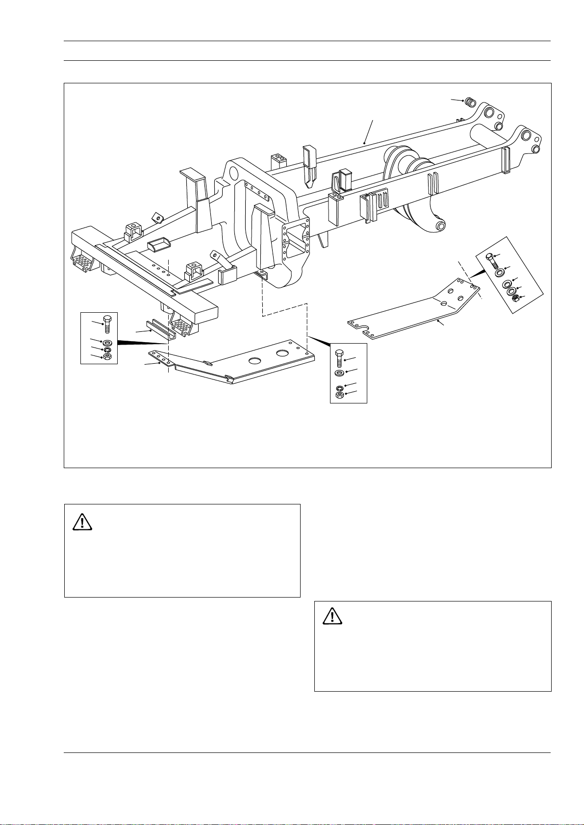
CHASSIS - Chassis, Hood and Fenders
Section 100-0010
2
1
9
8
7
6
4
3
5
8
7
6
10
SM - 1785
11
15
14
12
13
1 - Frame Assembly
2 - Bushing
3 - Engine Guard
4 - Channel
5 - Bolt
6 - Nut
7 - Lockwasher
Fig. 1 - Exploded View of Chassis and Guards
REMOVAL
WARNING
To prevent personal injury and property
damage, be sure wheel chocks, blocking
materials and lifting equipment are properly
secured and of adequate capacity to do the job
safely.
To remove any of the components shown in
Figs. 1, 2, 3, 4 or 5 (or similar components) the
following procedures should be carried out.
1. Position the vehicle in a level work area, apply the
parking brake and switch off the engine.
2. Turn steering wheel in both directions several times
to relieve pressure in the steering circuit. Block all road
wheels.
8 - Washer
9 - Bolt
10 - Transmission Guard
11 - Bolt
12 - Hardened Washer
13 - Locknut
14 - Spring Disc
15 - Washer
3. Attach a suitable lifting device to the component and
remove mounting hardware. Remove the component
from the vehicle.
INSTALLATION
Note: Tighten all fasteners to standard torques listed in
Section 300-0080, STANDARD BOLT AND NUT
TORQUE SPECIFICATIONS.
WARNING
To prevent personal injury and property
damage, be sure wheel chocks, blocking
materials and lifting equipment are properly
secured and of adequate capacity to do the job
safely.
Using a suitable lifting device, align the component to
be installed in position on the chassis. Secure the
component securely to the chassis with mounting
hardware removed during removal.
SM 1570 12-98
1
Page 14
Chassis - Chassis, Hood and Fenders
Section 100-0010
Inspection
Inspect the frame and attached parts at intervals not
exceeding 250 hours for cracked or broken welds and
bending/twisting of the frame. Any defects found
should be repaired before they progress into major
failures. Contact your dealer for recommended weld
and repair instructions.
SM - 1958MAINTENANCE
8
7
6
1
Welding
Note: It is important that the electrical connections are
disconnected in the following order to prevent damage
to the electrical components:
a. Disconnect battery equalizer ground cables.
b. Disconnect battery cables from terminal posts
(ground cable first).
c. Disconnect battery equalizer positive cables.
d. Disconnect electrical connections at the ECU.
After welding, reconnect all of the above in the reverse
order.
WARNING
Welding and flame cutting cadmium plated
metals produce odourless fumes which are
toxic. Recommended industrial hygiene
practice for protection of the welding operator
from the cadmium fumes and metallic oxides
requires enclosure ventilation specifically
designed for the welding process. A respiratory
protective device such as the M.S.A. 'Gasfoe'
respirator with G.M.A. cartridge will provide
protection against cadmium, fumes and
metallic oxides. The 'Gasfoe' respirator has
been approved by the U.S. Bureau of Mines:
Approval number
23B-10, and is designed to protect against
gases, vapours, and/or metal fumes.
Electric arc welding is recommended for all chassis
welding. Since the nature and extent of damage to the
frame cannot be predetermined, no definite repair
procedure can be established. As a general rule
however, if parts are twisted, bent or pulled apart, or a
frame is bent or twisted, no welding should be done
until the parts are straightened or realigned.
5
4
2
5
4
3
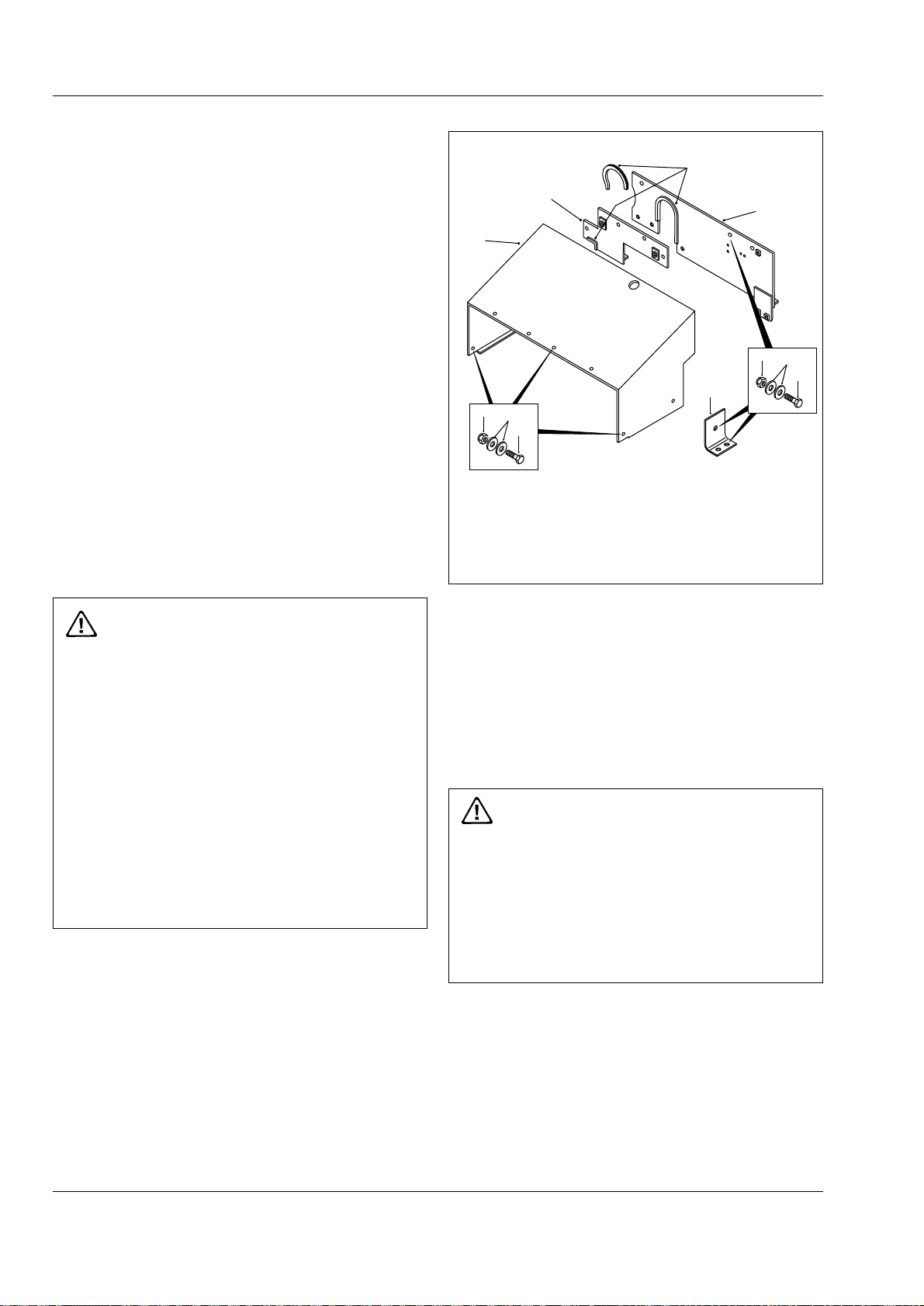
1 - Hood Assembly
2 - Plate
3 - Bolt
4 - Hardened Washer
Fig. 2 - Exploded View of Hood and Mounting
5 - Nut
6 - Baffle
7 - Baffle
8 - Beading
and the ability of the welder. The Service Department
can be consulted regarding the feasibility of welding
repairs.
Painting
A check of the condition of the paint should be made
approximately twice a year and chassis repainted if
necessary.
WARNING
Welding, burning, heating or dressing surfaces
previously painted using polyurethane paint
produces fumes which are toxic. Surfaces must
be prepared using paint stripper prior to area
being reworked. Recommended Industrial
Hygiene and Safety Rules should be be
followed for protection of the welding operator
from fumes.
If painting of the actual frame of the unit is required,
thoroughly clean the areas to be painted. Apply a
primer coat of red oxide and then a finish coat of
polyurethane enamel.
3
Successfully welded repairs will depend to a great
extent upon the use of the proper equipment, materials
2
To keep rust and corrosion to a minimum, periodic
painting of abrasions and other exposed metal areas on
the frame is highly recommended.
SM 1570 12-98
Page 15
32
23
18
DETAIL A
20
20
Chassis - Chassis, Hood and Fenders
Section 100-0010
SM - 1959
22
10
10
28
19
3
49
50
51
34
34
A
22
10
7
35
27
25
24
38
37
36
22
10
18
17
48
33
13
13
26
25
24
17
19
18
14
19
18
28
19
30
18
17
19
18
4
31
19
12
11
1
1
15
16
6
44
5
41
42
39
42
43
45
29
18
45
260-0010
17
19
SEC.
46
40
17
19
18
2
2
41
42
42
43
22
19
10
8
9
21
21
22
10
50
51
49
47
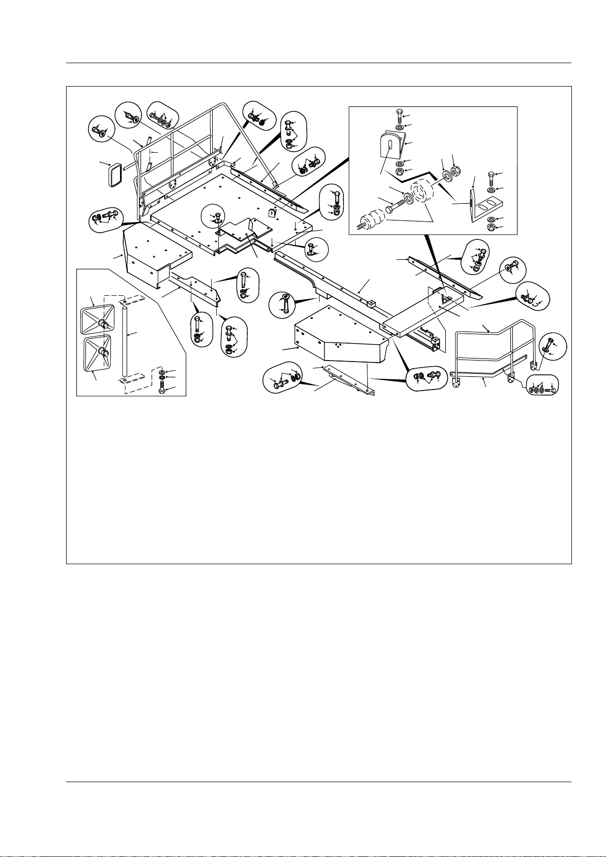
1 - LH Fender Assembly
2 - LH Platform Assembly
3 - RH Fender Assembly
4 - RH Platform Assembly
5 - Crossmember
6 - Support
7 - Support
8 - Bolt
9 - Lockwire
10 - Hardened Washer
11 - Bolt
12 - Washer
13 - Engine Access Cover
14 - Bolt
15 - Locknut
16 - Hardened Washer
17 - Bolt
18 - Locknut
19 - Hardened Washer
20 - Mirror
21 - LH Handrail
22 - Bolt
23 - Mirror Wide Angle
24 - Nut
25 - Washer
26 - Bolt
27 - Bolt
28 - Bolt
29 - Mudguard
30 - Mudguard
31 - Bolt
32 - Bolt
33 - Fender Extension RH
34 - RH Handrail
35 - Mirror Bracket
36 - Bolt
37 - Lockwasher
38 - Washer
Fig. 3 - Exploded View of Fenders and Mounting
39 - Plate Bent
40 - Plate bent
41 - Bolt
42 - Washer
43 - Nut
44 - Bolt
45 - Washer
46 - Nut
47 - Kick Plate
48 - Kick Plate
49 - Bolt
50 - Hardened Washer
51 - Nut
SM 1570 12-98
3
Page 16
Chassis - Chassis, Hood and Fenders
Section 100-0010
13
14
14
6
10
12
12
3
11
4
14
4
11
12
12
10
SM - 1960
13
14
14
6
3
4
14
4
11
12
12
10
9
7
7
8
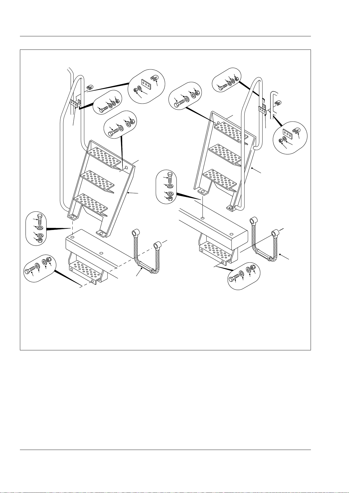
1 - LH Step Assembly
2 - RH Step Assembly
3 - Plate
11
12
2
12
10
5
7 - Washer
4 - 'U' Bolt
5 - Step
6 - Bolt
8 - Bolt
9 - Locknut
10 - Nut
Fig. 4 - Exploded View of Ladders and Handrails
9
7
7
8
11 - Bolt
12 - Hardened Washer
13 - Nut
14 - Hardened Washer
1
5
4
SM 1570 12-98
Page 17
Chassis - Chassis, Hood and Fenders
Section 100-0010
SM - 1961
1
9
12
12
6
10
11
12
5
12
12
6
7
12
13
8
11
3
4
2
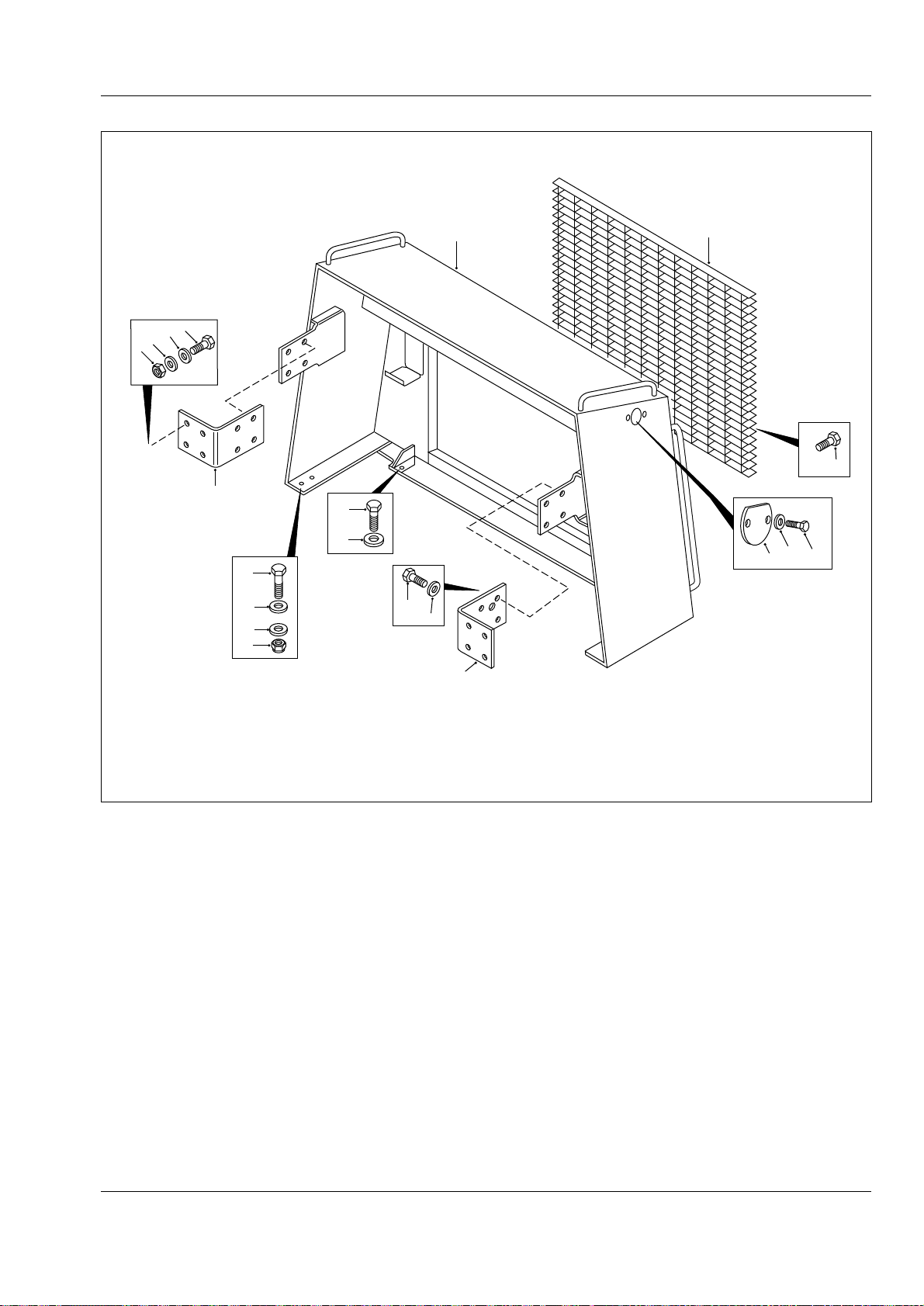
1 - Radiator Guard
2 - Cover Plate
3 - Washer
4 - Bolt
5 - Bolt
6 - Nut
7 - Bolt
8 - Grille
9 - Bolt
Fig. 5 - Radiator Guard and Mounting
* * * *
10 - Bracket
11 - Bolt
12 - Hardened Washer
13 - Plate
SM 1570 12-98
5
Page 18

THIS PAGE IS INTENTIONALLY LEFT BLANK
Page 19

GENERAL INFORMATION - Welding Procedure
Welding
WARNINGS
Before any welding is done on a machine
equipped with any electronic systems,
disconnect the following (if applicable) in this
order: Battery earth cable, battery supply
cable, alternator earth cables, alternator supply
cables and electrical connections at the engine
ECM, transmission ECU, body control lever,
hydraulics ECU and cab bulkhead to avoid
damage to electrical components. Turn off
battery master switch to isolate the batteries
before disconnecting any components.
After welding connect all of the above in the
reverse order.
Before any welding is done ensure all paint has
been removed from the area to be welded.
Failure to do so may result in hazardous fumes
being given off from the paint.
Note: Always fasten the welding machines ground
cable to the piece/frame being welded if possible.
Section 000-0010
WARNING
Welding and flame cutting cadmium plated
metals produce odourless fumes which are
toxic. Recommended industrial hygiene
practice for protection of the welding operator
from the cadmium fumes and metallic oxides
requires enclosure ventilation specifically
designed for the welding process. A
respiratory protective device such as the
M.S.A. 'Gasfoe' respirator with G.M.A. cartridge
will provide protection against cadmium,
fumes and metallic oxides. The 'Gasfoe'
respirator has been approved by the U.S.
Bureau of Mines: Approval number 23B-10,
and is designed to protect against gases,
vapours, and/or metal fumes.
Note: The current from the welding rod always follows
the path of least resistance. If, for example, the ground
clamp is attached to the rear frame when welding is
performed on the front frame, the current must pass a
frame connection to return to the welding machine.
Since the pivot coupling offers the least resistance but
not a sound electrical connection, small electric arcs
may be set up across the moving parts which may
cause welding blotches on their wearing surfaces and
increase the wear rate of these components.
Electric arc welding is recommended for all welded
frame repairs. Since the nature and extent of damage
to the frame cannot be predetermined, no definite
repair procedure can be established. As a general rule
however, if parts are twisted, bent or pulled apart, or a
frame is bent or out of alignment, no welding should be
done until the parts are straightened or realigned.
Successfully welded repairs will depend to a great
extent upon the use of the proper equipment, materials
and the ability of the welder. The Customer Support
Department can be consulted regarding the feasibility
of welding repairs.
General Welding Procedure
The following general procedure should be used for
the repair of defects outwith the vicinity of alloy steel
castings.
1. Completely ARC-AIR gouge or grind out the crack
until sound metal is reached. If ARC-AIR method is
employed, pre-heat area to 100° C (212° F), measure
3 - 4" either side of repair prior to gouging. On
completion of gouging grind to remove thin carbon
layer.
2. Apply dye-penetrant check to ensure crack has
been completely removed.
SM 2172 10-02
1
Page 20

General Information - Welding Procedure
Section 000-0010
3. Pre-heat area to 100° C (212° F), measured 3 - 4"
either side of repair. Avoid local overheating.
4. Weld completely using E-7016 electrodes. Care
must be taken to ensure electrodes are protected from
moisture pick-ups at all times.
5. Allow repair weld to cool slowly.
6. Grind and blend repair to original contour. Paint
heat damaged areas.
The following general procedure should be used for
the repair of defects in alloy steel castings and in the
welds joining steel castings.
1. Completely ARC-AIR gouge or grind out the crack
until sound metal is reached. If ARC-AIR method is
employed, pre-heat area to 200° C (392° F), measure
* * * *
3 - 4" either side of repair prior to gouging. On
completion of gouging grind to remove thin carbon
layer.
2. Apply dye-penetrant check to ensure crack has
been completely removed.
3. Pre-heat area to 200° C (392° F), measured 3 - 4"
either side of repair. Avoid local overheating.
4. Weld completely using E-7016 electrodes. Care
must be taken to ensure electrodes are protected from
moisture pick-ups at all times.
5. On completion of welding, post-heat repair area to
400° C (752° F), measure 3 - 4" either side of repair.
6. If welding has to be interrupted for any reason, e.g.
overnight, post-heat immediately as in Step 5.
2
SM 2172 10-02
Page 21
CHASSIS - Chassis, Hood and Fenders
Section 100-0010
SM - 2395
2
1
11
15
16
12
14
17
13
9
8
7
6
4
3
5
8
7
6
10
13
16
12
14
17
11
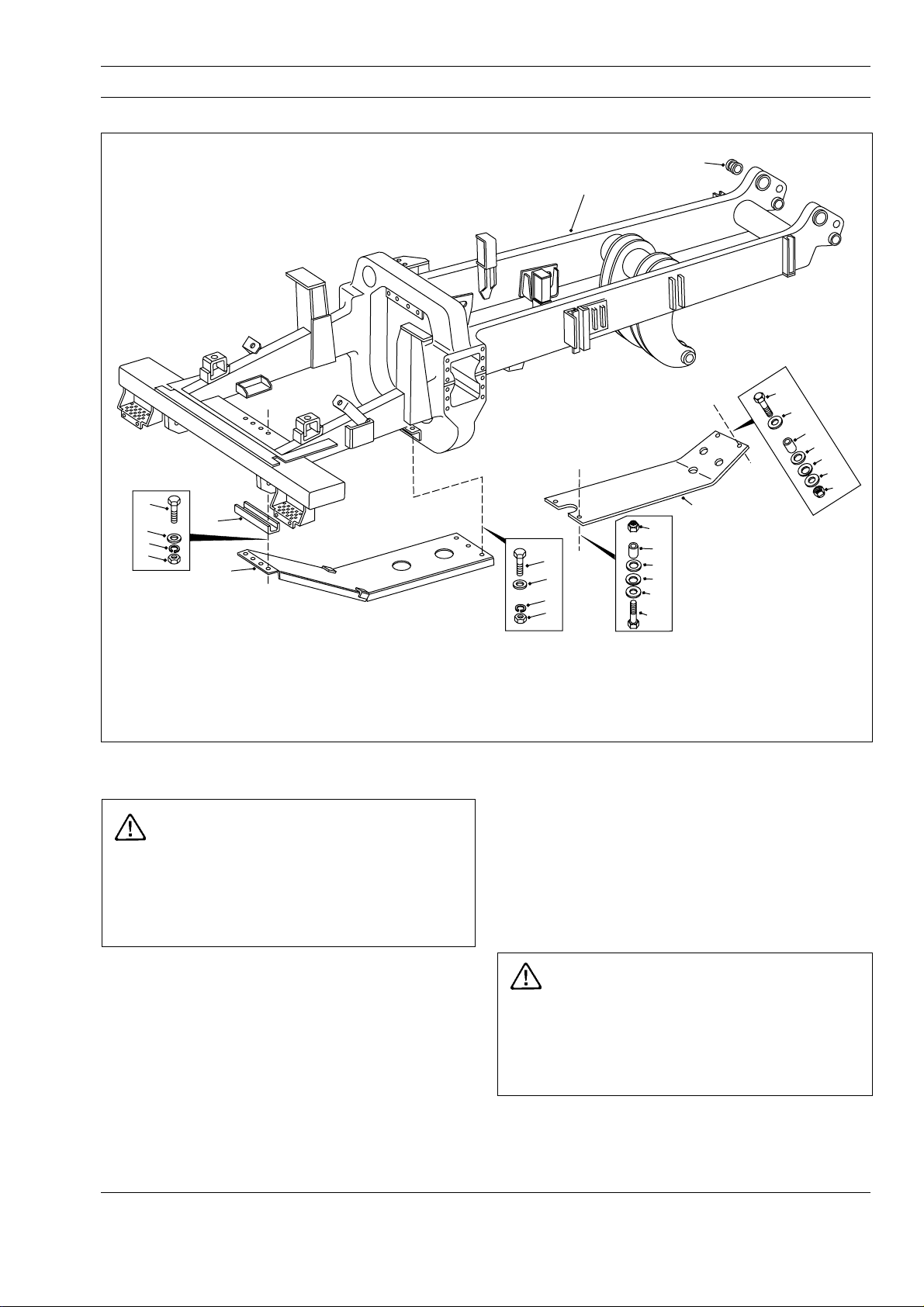
1 - Frame Assembly
2 - Bushing
3 - Engine Guard
4 - Channel
5 - Bolt
6 - Nut
7 - Lockwasher
8 - Washer
Fig. 1 - Exploded View of Chassis and Guards
REMOVAL
WARNING
To prevent personal injury and property
damage, be sure wheel chocks, blocking
materials and lifting equipment are properly
secured and of adequate capacity to do the job
safely.
To remove any of the components shown in
Figs. 1, 2, 3, 4 or 5 (or similar components) the
following procedures should be carried out.
1. Position the vehicle in a level work area, apply the
parking brake and switch off the engine.
2. Turn steering wheel in both directions several times
to relieve pressure in the steering circuit. Block all road
wheels.
13 - Locknut
9 - Bolt
10 - Transmission Guard
11 - Bolt
12 - Hardened Washer
14 - Spring Disc
15 - Washer
16 - Spacer
17 - Washer
3. Attach a suitable lifting device to the component and
remove mounting hardware. Remove the component
from the vehicle.
INSTALLATION
Note: Tighten all fasteners to standard torques listed
in Section 300-0080, STANDARD BOLT AND NUT
TORQUE SPECIFICATIONS.
WARNING
To prevent personal injury and property
damage, be sure wheel chocks, blocking
materials and lifting equipment are properly
secured and of adequate capacity to do the job
safely.
Using a suitable lifting device, align the component to
be installed in position on the chassis. Secure the
component securely to the chassis with mounting
hardware removed during removal.
SM 1904 1-00
1
Page 22
Chassis - Chassis, Hood and Fenders
Section 100-0010
Inspection
Inspect the frame and attached parts at intervals not
exceeding 250 hours for cracked or broken welds and
bending/twisting of the frame. Any defects found
should be repaired before they progress into major
failures. Contact your dealer for recommended weld
and repair instructions.
SM - 2396MAINTENANCE
8
7
6
1
Welding
Note: It is important that the electrical connections are
disconnected in the following order to prevent damage
to the electrical components:
a. Disconnect battery equalizer ground cables.
b. Disconnect battery cables from terminal posts
(ground cable first).
c. Disconnect battery equalizer positive cables.
d. Disconnect electrical connections at the ECU.
After welding, reconnect all of the above in the reverse
order.
WARNING
Welding and flame cutting cadmium plated
metals produce odourless fumes which are
toxic. Recommended industrial hygiene
practice for protection of the welding operator
from the cadmium fumes and metallic oxides
requires enclosure ventilation specifically
designed for the welding process. A
respiratory protective device such as the
M.S.A. 'Gasfoe' respirator with G.M.A. cartridge
will provide protection against cadmium,
fumes and metallic oxides. The 'Gasfoe'
respirator has been approved by the U.S.
Bureau of Mines: Approval number 23B-10,
and is designed to protect against gases,
vapours, and/or metal fumes.
Electric arc welding is recommended for all chassis
welding. Since the nature and extent of damage to the
frame cannot be predetermined, no definite repair
procedure can be established. As a general rule
however, if parts are twisted, bent or pulled apart, or a
frame is bent or twisted, no welding should be done
until the parts are straightened or realigned.
5
4
3
2
5
4
3
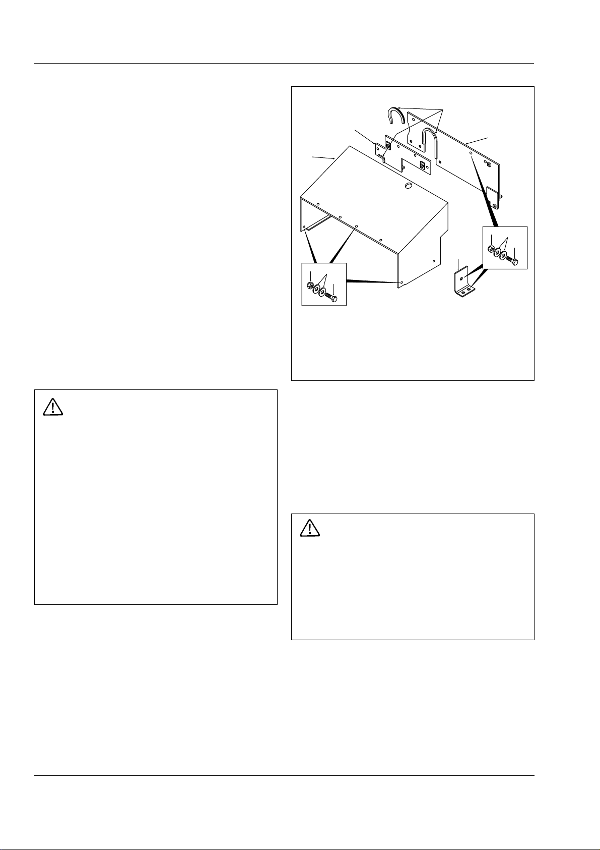
1 - Hood Assembly
2 - Plate
3 - Bolt
4 - Hardened Washer
Fig. 2 - Exploded View of Hood and Mounting
5 - Nut
6 - Baffle
7 - Baffle
8 - Beading
and the ability of the welder. The Service Department
can be consulted regarding the feasibility of welding
repairs.
Painting
A check of the condition of the paint should be made
approximately twice a year and chassis repainted if
necessary.
WARNING
Welding, burning, heating or dressing surfaces
previously painted using polyurethane paint
produces fumes which are toxic. Surfaces
must be prepared using paint stripper prior to
area being reworked. Recommended Industrial
Hygiene and Safety Rules should be be
followed for protection of the welding operator
from fumes.
If painting of the actual frame of the unit is required,
thoroughly clean the areas to be painted. Apply a
primer coat of red oxide and then a finish coat of
polyurethane enamel.
Successfully welded repairs will depend to a great
extent upon the use of the proper equipment, materials
2
To keep rust and corrosion to a minimum, periodic
painting of abrasions and other exposed metal areas
on the frame is highly recommended.
SM 1904 1-00
Page 23
Chassis - Chassis, Hood and Fenders
Section 100-0010
SM - 2397
22
32
10
10
42
23
28
19
18
3
A
22
10
7
27
25
24
22
10
18
33
13
26
25
24
17
19
18
14
17
19
18
28
19
30
18
17
19
18
4
31
19
12
11
1
15
16
6
36
41
34
39
38
37
34
35
37
29
5
17
19
18
41
40
34
34
35
17
19
18
2
21
22
19
10
8
9
22
10
20
45
48
47
55
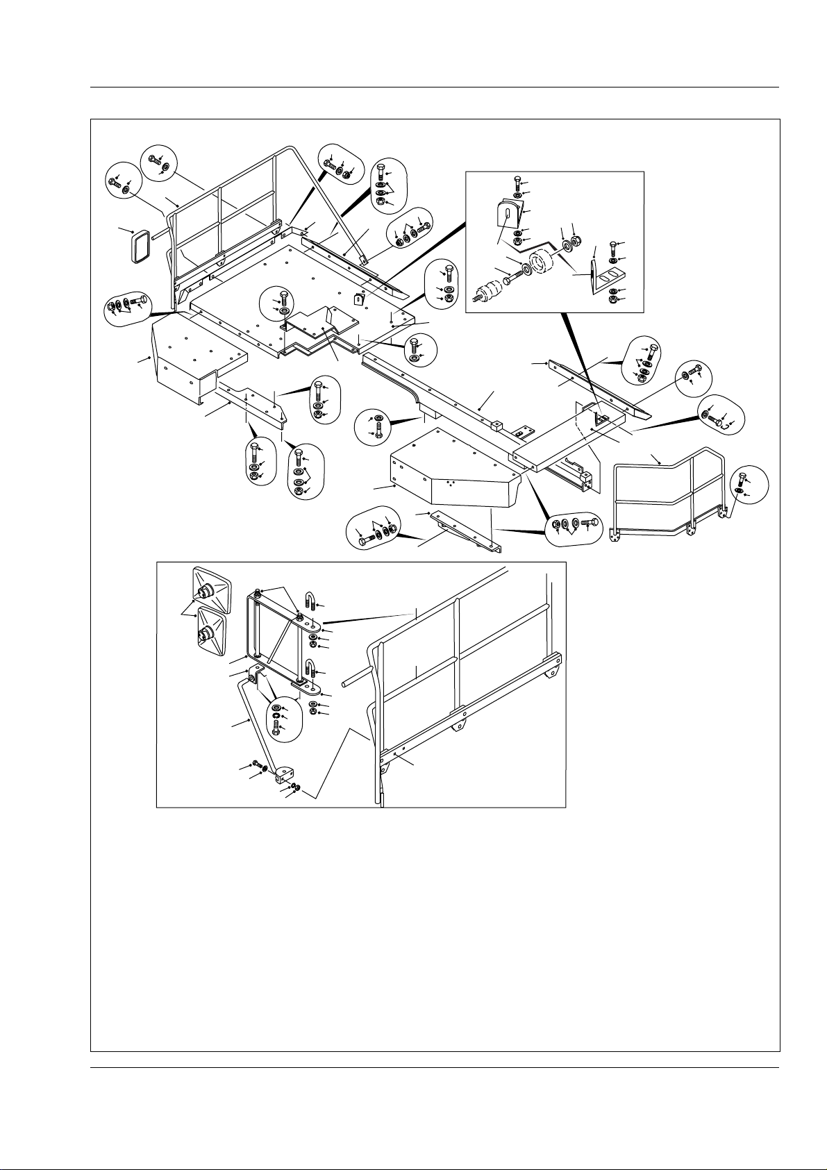
1 - LH Fender Assembly
2 - LH Platform Assembly
3 - RH Fender Assembly
4 - RH Platform Assembly
5 - Crossmember
6 - Support
7 - Support
8 - Bolt
9 - Lockwire
10 - Hardened Washer
11 - Bolt
12 - Washer
13 - Engine Access Cover
14 - Bolt
43,46,57
56
56
51
50
49
54
53
52
DETAIL A
44
57
43
44
57
43
A
43 - Nut
15 - Locknut
16 - Hardened Washer
17 - Bolt
18 - Locknut
19 - Hardened Washer
20 - Mirror
21 - LH Handrail
22 - Bolt
23 - Mirror Wide Angle
24 - Nut
25 - Washer
26 - Bolt
27 - Bolt
28 - Bolt
29 - Mudguard
30 - Mudguard
31 - Bolt
32 - Bolt
33 - Fender Extension RH
34 - Washer
35 - Nut
36 - Bolt
37 - Washer
38 - Nut
39 - Plate Bent
40 - Plate bent
41 - Bolt
42 - RH Handrail
44 - Plate
45 - Mirror Arm Assembly
46 - Bar
47 - Rod Assembly
48 - Bracket Assembly
49 - Bolt
50 - Lockwasher
51 - Washer
52 - Nut
53 - Lockwasher
54 - Washer
55 - Bolt
56 - 'U' Bolt
57 - Hardened Washer
SM 1904 1-00
Fig. 3 - Exploded View of Fenders and Mounting
3
Page 24
Chassis - Chassis, Hood and Fenders
Section 100-0010
13
14
14
6
10
12
12
3
11
4
14
4
11
12
12
10
SM - 1960
13
14
14
6
3
4
14
4
11
12
12
10
9
7
7
8
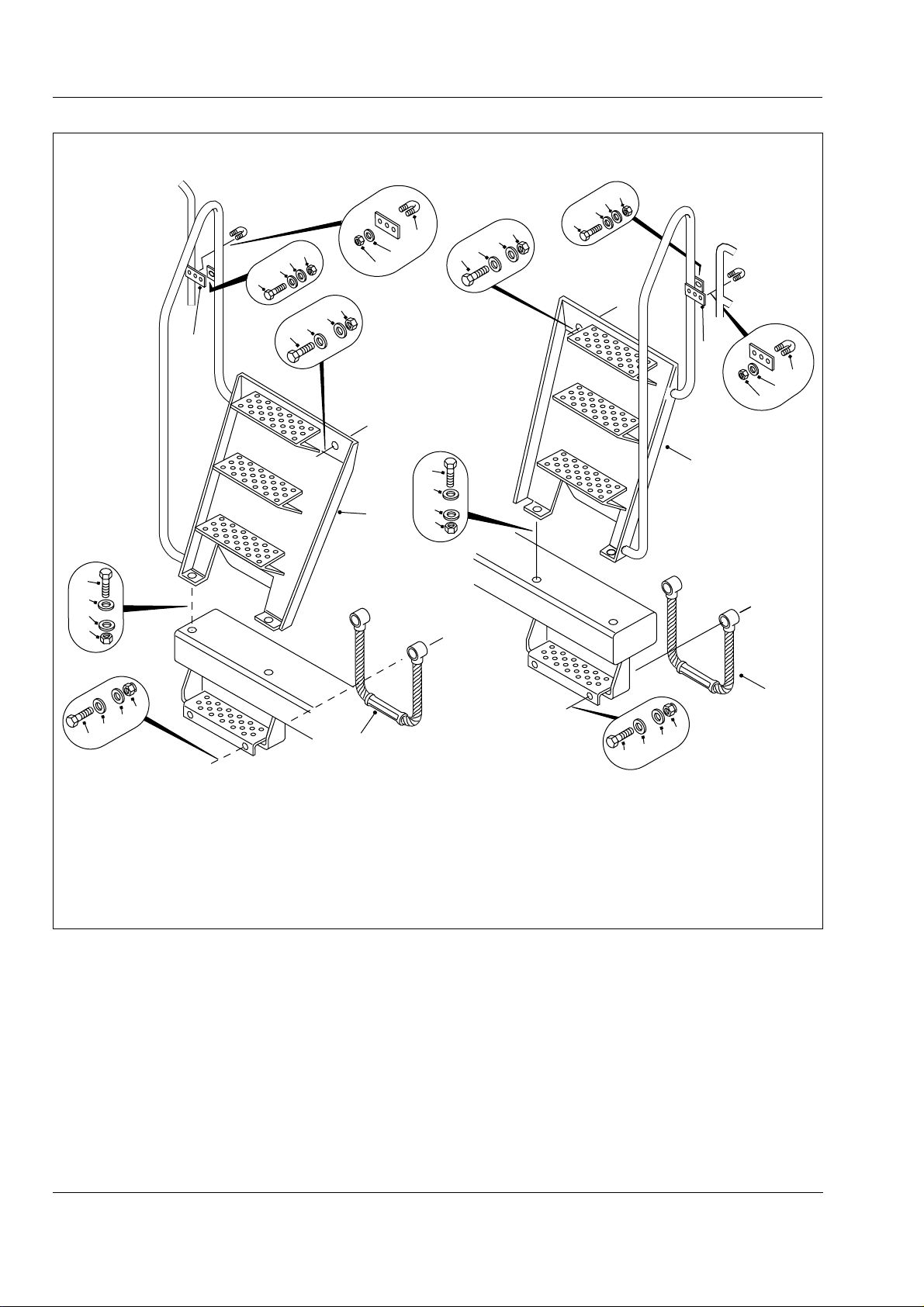
1 - LH Step Assembly
2 - RH Step Assembly
3 - Plate
11
12
2
12
10
5
7 - Washer
4 - 'U' Bolt & Nut
5 - Step
6 - Bolt
8 - Bolt
9 - Locknut
10 - Nut
Fig. 4 - Exploded View of Ladders and Handrails
1
9
7
7
8
11 - Bolt
12 - Hardened Washer
13 - Nut
14 - Hardened Washer
5
4
SM 1904 1-00
Page 25
Chassis - Chassis, Hood and Fenders
Section 100-0010
SM - 2398
8
1
7
11
6
10
5
11
2
9
7
11
3
4
11
11
12
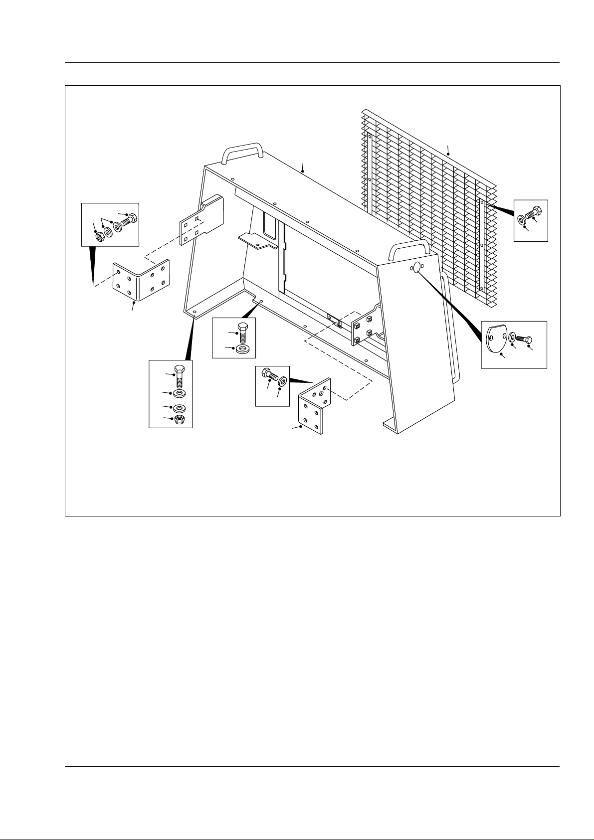
1 - Radiator Guard
2 - Cover Plate
3 - Washer
7
11
13
4 - Bolt
5 - Bolt
6 - Nut
7 - Bolt
8 - Grille
9 - Bolt
Fig. 5 - Radiator Guard and Mounting
* * * *
10 - Bracket
11 - Hardened Washer
12 - Nut
13 - Bracket
SM 1904 1-00
5
Page 26

THIS PAGE IS INTENTIONALLY LEFT BLANK
Page 27
ENGINE - Engine and Mounting
Section 110-0030
52
51
29
26
4
15
22,23
POSITION A
46
42
47
48
45
43
30
31
44
POSITION B
32
35
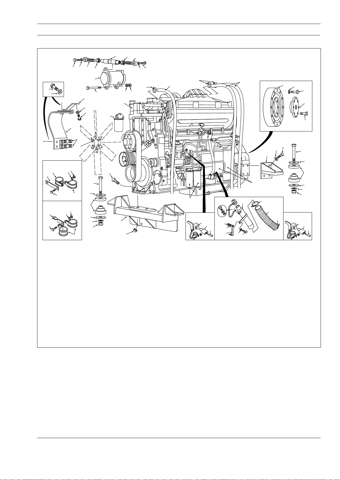
1 - Engine
2 - Locknut
3 - Bolt
4 - Alternator Guard
5 - Rear Mount
6 - Front Mount
7 - Bolt
8 - Lockwasher
9 - Support Bracket
10 - Bolt
11 - Snubbing Washer
12 - Isolation Mount
13 - Bolt
14 - Locknut
15 - Plate Support
16 - Damper
53
9
26
11
12
11
25
24
50
56
55
54
62
38
13
3
2
57
59
58
21
60
61
1
6
14
17 - Lockwasher
18 - Bolt
19 - Flange Coupling
20 - Bolt
21 - Clamp
22 - Bolt
23 - Lockwasher
24 - Washer
25 - Bolt
26 - Washer
27 - Padlock
28 - Key
29 - Bolt
30 - P-Clip
31 - P-Clip
32 - Bracket
33 - Latch Assembly
39
A
A
21
37
SECURITY KIT
ENGINE DIPSTICK
34
27
28
34 - Latch Assembly
35 - Bolt
36 - Oil Filter
37 - Fuel Filter
38 - Coolant Filter
39 - Breather Line
40 - Filler Hose
41 - Clamp
42 - Lockwasher
43 - Locknut
44 - Plate
45 - P-Clip
46 - Bolt
47 - Lockwasher
48 - Locknut
49 - Filler Assembly
50 - Alternator
BB
S.W.E.
66
65
63
65
39
49
64
5
36
41
40
51 - Bolt
52 - Lockwasher
53 - Eye Bolt
54 - Jam Nut
55 - Link
56 - Nut
57 - Eye Bolt
58 - Lockwasher
59 - Bolt
60 - Locknut
61 - Lockwasher
62 - Bolt
63 - Bracket
64 - Bolt
65 - Washer
66 - Locknut
8
41
16
7
SM - 1962
17
18
19
20
10
12
11
24
2
SECURITY KIT
ENGINE OIL FILL
33
27
11
28
Fig. 1 - Engine and Mounting
DESCRIPTION
Numbers in parentheses refer to Fig. 1.
For engine make, model and specification, refer to
Section 000-0000, GENERAL INFORMATION. For
engine servicing and repair data refer to the engine
manufacturers service manual.
The engine is mounted to the frame at three points by
a mounting bracket (6) at the front of engine (1) and
two rear mounts (5). Rubber isolation mounts (12)
SM 1571 12-98
through engine mounts provide sufficient flexibility to
absorb varying engine vibration and torsional loads.
There are two full-flow oil filters (36) mounted on the
left hand side of engine (1) in a downward position.
The filters are of the throw away, spin-on type. Oil
supplied by the engine oil pump passes through oil
filters (36) before reaching the various moving parts of
engine (1). The oil is forced by pump pressure through
a passage in the filter adaptor and into the elements.
Impurities are filtered out as the oil passes through the
1
Page 28
Engine - Engine and Mounting
Section 110-0030
elements and out through another passage in the filter
adaptor.
Engine coolant filter (38) and conditioner is a compact
bypass type unit with a replaceable spin-on type element
mounted on the gear case cover at the front right hand
side of engine (1). Refer to Section 210-0000,
COOLING SYSTEM.
There are two spin-on type fuel filters (37) mounted on
the left hand side of engine (1). The primary fuel filter
is in the fuel flow and acts as a strainer and the
secondary fuel filter filters the fuel after having passed
through the primary fuel filter.
QUANTUM ELECTRONIC FUEL CONTROL
SYSTEM
Description
Refer to Fig. 2.
WARNING
Before any welding is done on a machine
equipped with the Quantum Electronic Fuel
System, disconnect the following in this order:
Battery earth cable, battery supply cable,
alternator earth cables, alternator supply
cables, transmission black box connector,
ECM interface harness connector (30 pin RHS),
ECM power harness connector (5 pin RHS) and
ECM sensor harness connector (30 pin LHS).
Turn off ignition key switch to isolate the
batteries before disconnecting any
components.
After welding connect all of the above in the
reverse order.
The engine is equipped with Quantum Electronic Fuel
System which controls the timing and amount of fuel
injection by the electronic fuel system injectors. The
system also monitors several engine functions using
electrical sensors which send electrical signals to the
electronic control module (ECM). The ECM then
computes the incoming data and determines the
correct fuel output and timing for optimum power, fuel
economy and emissions.
The Quantum Electronic Fuel System also takes
action to prevent damage to the engine and, provides
the serviceman with diagnostic capabilities so that
problems can be corrected quickly and easily.
1. Electronic Control Module (ECM) - Receives
electronic inputs from the driver as well as from
mounted sensors that provide information
electronically, such as oil pressure and temperature
and intake manifold pressure. This information is
used to control both the quantity of fuel injected and
injection timing.
2. Programmable Read Only Memory (PROM) -
Located in the ECM and encoded with the operating
software. Additional information is programmed into
the EEPROM. This information controls the
horsepower rating, torque curve, maximum engine
speed and engine protection devices. The ECM
processes this information and sends electronic
signals to the Electronic Fuel System Injectors where
the precise amount of fuel is injected into the engine.
3. Electronic Fuel System Injectors - The injector is
a lightweight, compact unit that injects diesel fuel
directly into the combustion chamber. The amount of
fuel injected and the beginning of injection timing is
determined by the ECM. The ECM sends a command
pulse which activates the injector solenoid.
The injector performs four functions:
a - Creates the high fuel pressure required for efficient
injection.
b - Meters and injects the exact amount of fuel
required to handle the load.
c - Atomizes the fuel for mixing with the air in the
combustion chamber.
d - Permits continuous fuel flow for component cooling.
Electronic fuel system injectors are self compensating
and virtually eliminate engine tune-ups.
Note: Never apply 12 V directly to terminals on the
injector as it will burn out. Before removing injectors,
the fuel passages must be blown out to prevent fuel
flow from entering the cylinder head.
4. Batteries - Two 12 volt maintenance free batteries
supply the machine with electrical power to operate
all electrical components.
5. Electronic Foot Pedal - The electronic foot pedal
provides an electrical signal to the engine's fuel
control system in proportion to the degree of pedal
actuation.
Note: The electronically controlled engine will override
the electronic foot pedal position until the engine is
2
SM 1571 12-98
Page 29
Engine - Engine and Mounting
Section 110-0030
SM - 1791
4
1,2
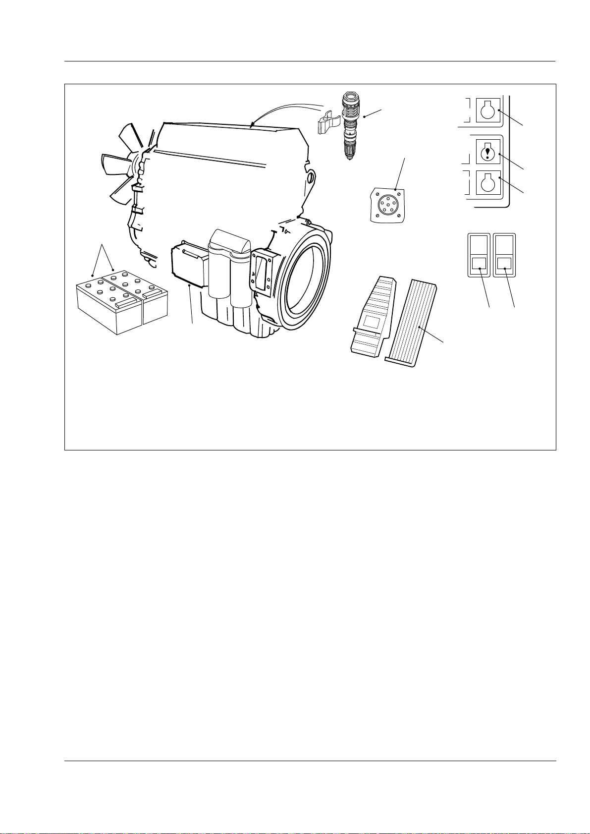
1 - Electronic Control Module (ECM)
2 - Programmable Read Only Memory (PROM)
3 - Electronic Fuel System Injectors
4 - Batteries
5 - Electronic Foot Pedal
3
9
5
6 - Engine 'Stop' Light
7 - Engine 'Warning' Light
8 - Engine 'Fluid' Light
9 - Diagnostic Test Point
10 - Diagnostic Request Switch
11 - Diagnostic Search Switch
STOP
6
7
8
10 11
Fig. 2 - Quantum Electronic Fuel System Components
warmed up to the correct operating temperature. The
engine MUST be started with foot 'OFF' the electronic
foot pedal.
6. Engine Stop Light (Red) - When the engine 'Stop'
light comes on, the computer has detected a major
malfunction in the engine that requires immediate
attention. It is the operators responsibility to shut down
the engine to avoid serious damage.
7. Engine Warning Light (Yellow) - When the engine
'Warning' light comes on, the computer has detected a
fault in the engine which may result in power loss. The
fault should be diagnosed and corrected at the earliest
opportunity.
8. Engine Protection Fluid Light (Amber) - When
the engine 'Fluid' light comes on, the computer has
detected a fault in the engine. The light will remain on
as long as the fault is occuring. The fault should be
diagnosed and corrected at the earliest opportunity. If
the fault continues to get worse the light will flash. Stop
the machine and do not operate until the fault is
corrected.
9. Diagnostic Test Point - Plug in connector for
diagnostic data reader (DDR).
10. Diagnostic Request Switch - To check for
active codes:
a - turn the ignition key switch to the 'OFF' ('0')
position.
b - press the diagnostic switch to the 'ON' position.
c - turn the ignition key switch to position '1'.
If no active codes are recorded the 'Stop', 'Warning'
and 'Fluid' lights will illuminate and stay on.
If active codes are recorded the 'Stop', 'Warning' and
'Fluid' lights will illuminate momentarily. The yellow
'Warning' and red 'Stop' lights will begin to flash the
code of the recorded fault.
11. Diagnostic Search Switch - When the engine is
in diagnostic mode this switch is used to search
through a list of fault codes, ie. pressing the top of the
switch momentarily will advance to the next active
SM 1571 12-98
3
Page 30
Engine - Engine and Mounting
Section 110-0030
fault code, pressing the bottom of the will go back to
the previous code.
On machines which have a Low Idle Adjustment
feature, this switch can also be used to increase or
decrease (in increments of 25 RPM), the idle or
intermediate speed of the engine.
Operation
Numbers in parentheses refer to Fig. 2.
The machine is equipped with the Quantum engine
protection system which records fault codes in the
ECM (1), when the engine malfunctions and when an
out-of-range condition is found.
When the 'Stop' light (6) on the dash panel illuminates,
the computer has detected a major malfunction in the
engine that requires immediate attention. It is the
operators responsibility to shut down the engine to
avoid serious damage.
When an out-of-range conditions is found, the 'Fluid'
light (8) illuminates and the engine protection system
is initiated. The 'Fluid' light will start to flash if the outof-range condition continues to get worse. The
operator MUST shut down the engine to avoid serious
damage.
The engine should not be restarted after it has been
shut down after activation of the engine protection
system unless the problem has been diagnosed and
corrected.
Conditions that will cause the amber 'Fluid' light (8) to
come on are; Low coolant level, High coolant
temperature, Idle validation/throttle pedal switch
mismatch, High intake manifold temperature, Low oil
pressure and High fuel rail pressure.
Whenever the 'Stop' light (6), 'Warning' light (7) or
'Fluid' light (8) come on, the Electronic Fuel System
computer will determine where the problem is and will
store this information in its memory. If the malfunction
is intermittent, the lights will come on and go off as the
computer senses the changing engine condition.
A special diagnostic data reader (INSITE) is available
that can be plugged into the engine computer memory
via the onboard diagnostic test point (9). The reader
is used to extract information related to the cause of
the problem. Once the malfunction has been
corrected, the Electronic Fuel System will return the
engine to normal operation. The data reader can now
distinguish between active codes and those stored in
the historic code memory (inactive codes). Inactive
codes can only be viewed using the data reader. The
fault code recorded in the ECM memory will remain
until it is erased by a technician.
WARNINGS
The operator of a Quantum-equipped vehicle
must not attempt to use or read a data reader
of any kind while the vehicle is operating.
Doing so can result in loss of control, which
may cause vehicle damage and may result in
personal injury.
The operator can check for active faults by turning the
ignition key switch to the 'OFF' position, switching the
diagnostic switch 'ON' and then turning the ignition key
switch to position '1'.
If no active fault codes are recorded, all three ('Stop',
'Warning' & 'Fluid') lights will come on and stay on. If
active codes are recorded, all three lights will come on
momentarily. The yellow ('Warning') and red ('Stop')
lights will begin to flash the code of the recorded fault.
The fault codes flash in the following sequence: the
yellow light flashes once, then there is a pause where
both lights are off. Then the numbers of the recorded
fault code flash in red. There is a pause between each
number. When the number is done, the yellow light
flashes again. e.g. yellow flashes once - pause - red
flashes twice - pause - red flashes three times - pause
- red flashes five times - pause - yellow flashes once,
indicates fault code 235. The number will repeat in the
same sequence until the the system is advanced to
the next active fault code or the diagnostic switch is
switched to the 'OFF' position. Refer to 'Electronic Fuel
System Diagnostic Codes' table for fault code
descriptions.
4
SM 1571 12-98
Page 31
Engine - Engine and Mounting
Section 110-0030
ELECTRONIC FUEL SYSTEM DIAGNOSTIC CODES
Error Code Description Fault Lamp
111 ECM Hardware Internal Failure - Mission disabling Red
112 Timing Actuator - Mechanically stuck Red
113 Timing Actuator - Component shorted high Yellow
114 Timing Actuator - Component shorted low Yellow
115 Engine Speed Sensor - Both signals lost Red
116 Fuel Timing Pressure Sensor - Component shorted high Red
117 Fuel Timing Pressure Sensor - Component shorted low Red
118 Fuel Pump Pressure Sensor - Component shorted high Yellow
119 Fuel Pump Pressure Sensor - Component shorted low Yellow
121 Engine Speed Sensor - One signal lost Yellow
122 Boost Pressure Sensor - Component shorted high Yellow
123 Boost Pressure Sensor - Component shorted low Yellow
131 Throttle Position Sensor - Component shorted high Red
132 Throttle Position Sensor - Component shorted low Red
135 Oil Pressure Sensor - Component shorted high Yellow
141 Oil Pressure Sensor - Component shorted low Yellow
143 Oil Pressure Sensor - Data below normal range Amber
144 Engine Coolant Temperature Sensor - Component shorted high Yellow
145 Engine Coolant Temperature Sensor - Component shorted low Yellow
151 Engine Coolant Temperature Sensor - Data above normal range Amber
153 Intake Manifold Temperature Sensor - Component shorted high Yellow
154 Intake Manifold Temperature Sensor - Component shorted low Yellow
155 Intake Manifold Temperature Sensor - Data above normal range Amber
221 Ambient Air Pressure Sensor - Component shorted high Yellow
222 Ambient Air Pressure Sensor - Component shorted low Yellow
231 Coolant Pressure Sensor - Component shorted high Yellow
232 Coolant Pressure Sensor - Component shorted low Yellow
233 Coolant Pressure, Engine Protection - Low coolant pressure Amber
234 Engine Speed - Data above normal range Red
235 Engine Coolant Level - Data below normal range Amber
254 Fuel Shutoff Value - Component shorted low Red
259 Fuel Shutoff Solenoid - Fuel shutoff valve stuck open Red
261 Fuel Temperature, Engine Protection - Fuel temperature high Amber
263 Fuel Temperature Sensor - Component shorted high Yellow
265 Fuel Temperature Sensor - Component shorted low Yellow
316 Fuel Pump Actuator - Component shorted high or low Yellow
318 Fuel Pump Flow - Mismatch between estimated and desired pressures Yellow
342 ECM Not Calibrated - ECM software mission disabling failure Red
343 ECM Hardware Failure - Warning non mission disabling Yellow
346 ECM Software - Read/write, checksum error - Non mission disabling Yellow
415 Oil Pressure Sensor - Data indicates very low oil pressure Amber
422 Engine Coolant Level Sensor Signals - Data invalid Yellow
423 Fuel Timing Pressure Sensor - In-range failure Yellow
431 Throttle Position Idle Validation Switch - Invalid Yellow
432 Throttle Position Idle Validation Switch - Switch position & throttle percent mismatch Amber
441 Battery Voltage, Unswitched - Data below normal engine range Yellow
442 Battery Voltage, Unswitched - Data above normal engine range Yellow
451 Fuel Pressure Sensor - Component shorted high Red
452 Fuel Pressure Sensor - Component shorted low Red
455 Fuel Control Valve - Component shorted high or open Red
467 Timing Fueling Flow - Mismatch between estimated and desired timing Yellow
468 Fueling Rail Flow - Mismatch between estimated and desired rail pressure Yellow
511 Fuel Control Valve - Component shorted low Red
514 Fuel Control Valve - Actuator mechanically stuck open Red
524 Alternate Droop Switch Fault Yellow
551 Idle Validation Circuit - No voltage detected on both off-idle and idle pins Red
553 Engine Fueling Pressure Exceeded - Data above normal range Red
554 Fuel Pressure Sensor - In-range failure Yellow
555 Blowby Pressure, Engine Protection - Blowby pressure high Amber
719 Blowby Pressure Sensor - Component shorted high Yellow
729 Blowby Pressure Sensor - Component shorted low Yellow
753 Engine Speed Sensor - Engine speed signals do not match Off
SM 1571 12-98
5
Page 32
Engine - Engine and Mounting
Section 110-0030
REMOVAL
Numbers in parentheses refer to Fig. 1.
Note: Tag all cables, harnesses, lines and pipes
disconnected during removal to aid in installation.
WARNINGS
To prevent personal injury and property
damage, be sure wheel blocks, blocking
materials and lifting equipment are properly
secured and of adequate capacity to do the job
safely.
High electrical current can cause sparks
and personal injury from burns. Turn ignition
key switch to the 'Off' position before
removing any components. Remove battery
ground cable first, and reconnect last, to avoid
damaging electrical components.
1. Position the vehicle in a level work area, ensure the
body is fully lowered, apply the parking brake and
switch off the engine.
2. Turn steering wheel several times to relieve
pressure in the steering circuit. Block all road wheels.
3. Disconnect battery cables from battery terminal
ports before starting removal procedures. Disconnect
ground cable first.
7. If the truck is equipped with an air conditioning
system, evacuate refrigerant from the system and
disconnect lines at the compressor. Refer to Section
260-0130, AIR CONDITIONING.
8. With suitable containers in position, open drain cocks
and drain coolant from the radiator and engine (1)
assembly. Close all drain cocks after draining.
9. Identify cooling lines for ease of installation and with
suitable containers in position, disconnect cooling lines
from engine (1). Cap open line ends and fittings.
10. Using suitable lifting equipment, carefully remove
the radiator assembly from the vehicle. Refer to
Section 210-0040, RADIATOR AND MOUNTING.
11. Disconnect and remove air cleaner intake pipe
from the engine turbocharger and air cleaner.
12. Disconnect and remove exhaust tube from the
engine turbocharger.
13. Identify heater lines for ease of installation and,
with a suitable container in position, disconnect heater
lines from engine (1). Cap open line ends and fittings.
14. Close fuel shutoff valve at filter head, identify fuel
lines for ease of installation and, with a suitable
container in position, disconnect fuel lines from
engine (1). Cap open line ends and fittings.
4. Remove mounting hardware securing the hood on
the vehicle. Remove hood assembly from the vehicle.
5. Disconnect electrical connections from the radiator
guard and remove mounting hardware securing the
radiator guard on the vehicle. Remove radiator guard
from the vehicle.
6. Place a suitable container under the engine drain
port, remove drain plug and drain the oil. After
draining, reinstall drain plug in the engine sump and
tighten securely.
WARNING
Harmful gas. Before disconnecting any air
conditioner lines refer to Section 260-0130, AIR
CONDITIONING. Refrigerant will rapidly freeze
all objects with which it comes into contact,
and it can cause serious damage to the skin
and eyes.
15. Identify all electrical harnesses and cables
attached to engine (1) for ease of installation and
disconnect from engine (1).
16. Disconnect driveline from engine coupling and
secure clear of engine (1). Refer to Section 130-0010,
FRONT DRIVELINE.
17. Remove tandem pump from the engine power
takeoff. Refer to Section 230-0050, TANDEM PUMP.
Note: The hydraulic lines can be left attached to the
tandem pump.
WARNING
Heavy assembly. To prevent personal injury
and property damage, be sure lifting device is
of adequate capacity and properly secured to
do the job safely.
6
SM 1571 12-98
Page 33

Engine - Engine and Mounting
Section 110-0030
18. Attach suitable lifting equipment to the lifting
brackets on engine (1) assembly and raise lifting
equipment to take up the slack.
19. Remove locknuts (14) and bolts (13) securing
engine (1) assembly to front mounting (6). Remove
locknuts (2), washers (24), snubbing washers (11) and
bolts (10) securing rear mounting brackets (5) to the
frame.
20. Check to make certain that all necessary line and
electrical disconnections have been made before lifting
engine (1).
21. Carefully lift engine (1) assembly clear of the
frame and move to a clean work area. Securely
mount engine (1) assembly to a work stand.
DISASSEMBLY
Numbers in parentheses refer to Fig. 1.
1. If required, remove bolts (7) and lockwashers (8)
securing rear mounts to engine (1). Remove rear
mounts (5).
2. If required, remove rubber isolation mounts (12)
from rear mounts (5).
Note: Adjuster screw and link assembly (53 thru 57)
will have been released when removing radiator
assembly from the vehicle.
8. Remove bolt (51) and lockwasher (52) securing
screw and link assembly (53 thru 57) to alternator (50).
Support alternator (50) and remove locknut (60),
lockwasher (61) and bolt (62). Remove alternator (50)
from engine (1).
9. If necessary, damper (16) can be removed from the
flywheel after the power takeoff assembly is removed.
Refer to Section 110-0130, POWER TAKEOFF.
10. With power takeoff assembly removed, remove
bolts (18) and washers (17). Remove damper (16)
from engine (1). If necessary, remove bolts (20) from
flange coupling (19). Remove flange coupling (19) from
damper (15).
11. If required, remove bolt (64), washers (65) and
locknut (66) securing filler assembly (49) to bracket
(63). Loosen bottom clamp (41) and remove filler
hose (40) and filler assembly (49) from engine (1).
12. Remove and discard filters (36, 37 & 38) from
engine (1), as described in 'Maintenance'. Cover
engine inlet ports to prevent entry of dirt.
3. Remove bolts (22) and lockwashers (23) securing
fan to engine (1) then remove fan.
4. Loosen the fan hub mounting bolts and turn the
adjusting rod anticlockwise enough to allow slack in
poly 'V' belts. Remove poly 'V' belts.
5. If equipped with air conditioning, loosen compressor
drive belt and remove compressor from engine (1).
Refer to Section 260-0130, AIR CONDITIONING.
6. Remove bolts (25 & 29) and lockwashers (26)
securing alternator guard (4) to engine (1). Remove
alternator guard (4).
7. Loosen alternator mounting bolt (62) to allow slack
in 'V' belts. Remove 'V' belts.
13. Refer to 'Engine Manufacturers Service Manual' if
engine service or repair is required.
INSPECTION
Numbers in parentheses refer to Fig. 1.
1. Inspect rubber isolation mounts (12) for damage and
replace if required.
2. Check rear mounts (5), front mounting bracket (6)
and mounting brackets on the front frame for cracks
and/or damage. Repair or replace as necessary.
3. Inspect engine damper (16) and flange coupling (19)
for damage and repair or replace as required.
SM 1571 12-98
7
Page 34
Engine - Engine and Mounting
Section 110-0030
ASSEMBLY
Numbers in parentheses refer to Fig. 1.
Note: Tighten all fasteners without special torques
specified to standard torques listed in Section
300-0080, STANDARD BOLT AND NUT TORQUE
SPECIFICATIONS.
1. Remove covers from engine filter ports and install
new filters (36, 37 & 38) on engine (1), as described in
'Maintenance'.
2. If removed, secure filler hose (40) and filler
assembly (49) to engine (1) with bottom clamp (41).
Secure filler assembly (49) to bracket (63) using bolt
(64), washers (65) and locknut (66).
3. Install damper (16) to rear of engine (1) and secure
with bolts (18) and washers (17). Install flange
coupling (19) to damper (16) and secure with bolts (20).
4. Position alternator (50) on engine mounting bracket
and align the holes in the alternator mounting flanges
with the tube in the bracket. Secure alternator (50) in
position with bolt (62), lockwasher (61) and locknut
(60). Tighten bolt (62) finger tight at this stage.
5. Install adjuster screw and link assembly (53 thru 57)
to alternator (50) and secure with bolt (51) and
lockwasher (52). Tighten bolt (51) finger tight at this
stage.
Note: Replace all belts in a set when one is broken or
replaced.
6. Install 'V' belts in the grooves of alternator (50) and
accessory drive pulley.
Note: Alternator belt tension adjustment is made after
installation of engine (1) and the radiator assembly.
7. If equipped with air conditioning, install air
conditioner compressor and drive belt to engine (1).
Refer to Section 260-0130, AIR CONDITIONING.
8. Install poly 'V' belts to the fan pulley and crankshaft
pulley.
9. Adjust poly 'V' belts by turning the adjusting screw
clockwise until the correct tension is obtained. Refer to
'Drive Belt Adjustments'. When correct tension is
obtained tighten fan hub mounting bolts to a torque of
101 - 126 Nm (75 - 93 lbf ft).
10. Position fan to fan pulley on engine (1) and secure
with bolts (22) and lockwashers (23). Tighten bolts (22)
in a star shaped pattern to a torque of 34 Nm (25 lbf ft).
11. If removed, install rubber isolation mounts (12) to
front mounting bracket (6).
12. Secure rear mounts (5) to engine (1) with bolts (7)
and lockwashers (8) as identified at disassembly.
Tighten bolts (7) to a torque of 150 Nm (110 lbf ft). If
removed, install rubber isolation mounts (12) in rear
mounts (5).
INSTALLATION
Numbers in parentheses refer to Fig. 1.
Note: Tighten all fasteners without special torques
specified to standard torques listed in Section
300-0080, STANDARD BOLT AND NUT TORQUE
SPECIFICATIONS.
WARNING
To prevent personal injury and property
damage, be sure lifting device is properly
secured and of adequate capacity to do the job
safely.
1. Attach suitable lifting equipment to engine (1) lifting
brackets and carefully position engine (1) assembly in
the frame.
2. Secure engine (1) assembly to rear mounts on the
frame with bolts (10), snubbing washers (11) washers
(24) and locknuts (2). Secure engine (1) assembly to
front mounting bracket (6) with bolts (13) and locknuts
(14).
3. Connect driveline to the engine coupling. Refer to
Section 130-0010, FRONT DRIVELINES.
4. Install tandem pump on power takeoff assembly and
secure with mounting hardware. Refer to Section
230-0050, TANDEM PUMP.
5. Using suitable lifting equipment, install the radiator
assembly to the frame and secure with mounting
hardware. Refer to Section 210-0040, RADIATOR
AND MOUNTING.
6. Adjust 'V' belts by loosening locknut (54) and turning
screw assembly (55) clockwise until the correct
tension is obtained (refer to 'Drive Belt Adjustments').
When correct tension is obtained tighten locknut (54).
8
SM 1571 12-98
Page 35

Engine - Engine and Mounting
Section 110-0030
7. Tighten bolt (62) securing alternator (50) to engine
mounting bracket and bolt (51) securing link (53)
assembly to alternator (50) to a torque of 81 - 95 Nm
(60 - 70 lbf ft).
8. Remove caps from all cooling lines and connect
lines to the radiator assembly and engine (1) assembly
as identified at removal.
9. Install air cleaner intake pipe and exhaust piping to
engine turbocharger. Tighten mounting clamps
securely.
10. Remove caps from heater lines and fittings and
connect heater lines to engine (1) as identified at
removal.
11. Remove caps from fuel lines and fittings and
connect fuel lines to engine (1) as identified at removal.
12. Connect all electrical harnesses and cables to
engine (1) (with the exception of battery connections)
as identified at removal.
13. If the vehicle is equipped with air conditioning,
connect the lines at the compressor as identified at
removal. On completion of engine installation the air
conditioning system will require to be charged. Refer
to Section 260-0130, AIR CONDITIONING.
19. Fill the engine with lube oil specified in Section
300-0020, LUBRICATION SYSTEM. Check oil level
as described under 'Maintenance'.
20. Start up the engine and bring the engine oil to
operating temperature. Check all lines and fittings for
leaks and tighten as required.
21. Ensure parking brake is applied and remove wheel
blocks from all road wheels.
MAINTENANCE
Numbers in parentheses refer to Fig. 1.
Note: Carry out the following maintenance procedures
in conjunction with additional procedures listed in
Section 300-0020, LUBRICATION SYSTEM.
Every 10 Hours (Daily)
Engine (1): Visually check engine for damage, loose
or frayed belts and listen for any unusual noises.
Check the turbocharger for leaks.
Engine (1) Oil Level: Check engine oil level and add
oil if low. To allow checking before starting as well as
immediately after shutting down the engine, the
dipstick is provided with two types of marks:
14. Using suitable lifting equipment, install radiator
guard assembly to the frame. Secure with the required
mounting hardware and connect electrical connections
as identified at removal.
15. Using suitable lifting equipment, install hood
assembly into position on the vehicle. Secure hood
assembly with mounting hardware removed at
removal.
16. Connect battery positive connections to battery
terminal posts. Connect battery earth connections to
battery terminal posts.
17. Ensure all lines, harnesses and cables are
secured with clips and clamps as removed during
removal. Ensure no lines are chaffing on sharp edges
or resting against areas where heat will be evident.
Ensure all drain plugs and cocks are secured tightly.
18. Fill the cooling system with coolant specified in
Section 300-0020, LUBRICATION SYSTEM. Check
the coolant level as described in Section 210-0000,
COOLING SYSTEM.
1. Dot Marks - Before starting up after a major shut
down period the oil level should be up to the top dot
mark (cold level).
2. Dash Marks - Upon shutting down the engine at low
idling (wait 1 to 2 minutes) the oil level should be up to,
but not over, the top dash mark (hot level).
Every 250 Hours
Engine (1): Drain engine oil and refill. Refer to Section
300-0020, LUBRICATION SYSTEM for oil
specification.
Engine Water Pump: Inspect water pump drain hole
and clean if required.
Engine Oil Filters (36): Replace oil filters as follows:
1. Using filter wrench, remove and discard both oil
filters (36) from engine (1). Inspect the sealing
surface of the filter to ensure that the seal ring stayed
with the filter. If not, remove it from the filter adaptor.
2. Clean the filter adaptor with a clean, lint free cloth.
SM 1571 12-98
9
Page 36

Engine - Engine and Mounting
Section 110-0030
3. Lightly coat new oil filter (36) seal with clean
engine oil as specified in Section 300-0020,
LUBRICATION SYSTEM.
4. Start a new oil filter (36) on the filter adaptor and
tighten it by hand until the seal touches the adaptor
filter head. Tighten an additional 2/3 of a turn after
contact.
Note: Mechanical tightening of oil filters (36) is not
necessary and will distort or crack the adaptor. Tighten
oil filters by hand only.
5. Repeat steps 3 and 4 for second oil filter (36).
6. Start and run the engine for a short period and
check for oil leaks. If any leaks are noted, have them
corrected.
7. After the engine has been stopped long enough
(approximately 20 minutes) for the oil from various
parts of engine (1) to drain back to the crankcase,
check oil level and add oil to bring it to the proper level
on the dipstick. Refer to Section 300-0020,
LUBRICATION SYSTEM for oil specification.
Fuel Filters (37): Replace primary and secondary fuel
filters as follows:
Note: There is a fuel system shut off valve on the
discharge side of secondary fuel filter. Closing this
valve will prevent loss of fuel prime at time of filter
replacement.
1. Close shut off valve at secondary fuel filter and,
using filter wrench, remove and discard both fuel filters
from engine (1).
2. Fill the replacement filters and coat the gaskets
slightly with clean fuel oil as specified in Section
300-0020, LUBRICATION SYSTEM.
3. Start a new fuel filter on the filter adaptor and
tighten it by hand until the gasket contacts the adaptor
fully with no side movement of the filter evident.
Tighten an additional 1/2 of a turn.
Note: Mechanical tightening of fuel filters is not
recommended, and may result in seal and/or cartridge
damage. Tighten fuel filters by hand only.
4. Repeat step 3 for second fuel filter.
Coolant Filter (38): Check condition of coolant
inhibitor as described in Section 210-0000, COOLING
SYSTEM. Replace coolant filter (38) as follows:
Note: There is a shut off valve at the coolant inlet
and outlet lines of coolant filter (38). Closing these
valves will enable coolant filter (38) to be replaced
without an excessive loss of coolant.
1. Close shut off valves at coolant filter (38) inlet and
outlet lines and, using filter wrench, remove and
discard coolant filter (38) from engine (1).
2. Clean the filter adaptor with a clean, lint free cloth.
3. Lightly coat new coolant filter (38) seal with clean
engine oil as specified in Section 300-0020,
LUBRICATION SYSTEM.
4. Start coolant filter (38) on the filter adaptor and
tighten it by hand until the seal touches the adaptor
filter head. Tighten an additional 2/3 of a turn after
contact.
Note: Mechanical tightening of coolant filter (38) is not
necessary and will distort or crack the adaptor. Tighten
oil filters by hand only.
5. Open shut off valves at coolant filter (38) inlet and
outlet lines.
6. Start the engine and check for leaks. If any leaks
are noted, have them corrected. Add coolant as
required. Refer to Section 210-0000, COOLING
SYSTEM.
Drive Belt Adjustments
Every 50 Hours: Check all drive belt tensions and
adjust if required. If vehicle is equipped with air
conditioning, compressor belts should be checked and
adjusted as described in Section 260-0130, AIR
CONDITIONING.
Every 2 000 Hours: Replace all drive belts.
Note: Replace all belts in a set when one is worn.
Single belts of similar size should not be used as a
substitute for a matched belt set as premature belt
wear can result due to belt length variation. All belts in
a matched belt set are within 0.81 mm (0.032 in) of
their specified centre distances.
5. Start the engine and check for leaks. If any leaks
are noted, have them corrected.
10
SM 1571 12-98
Page 37
Engine - Engine and Mounting
Section 110-0030
Using belt tension gauge, adjust the belt tension to
the following values:
Fan - Poly 'V' Belt
Belt Tension 'New' - 3 340 N (750 lbf)
Belt Tension 'Used' - 2 450 - 3 340 N (550 - 750 lbf)
Alternator - 'V' Belt
Belt Tension 'New' - 556 N (125 lbf)
Belt Tension 'Used' - 445 N (100 lbf)
Note: A belt is considered 'Used' if it has been in
service for 10 minutes or longer. If the used belt
tension is less than the minimum value, tighten the
belt to the maximum value.
Belts should be neither too tight nor too loose. Belts
that are too tight impose excess loads on the
crankshaft, fan and alternator bearings, shortening
both belt and bearing life. Excessively overtightened
belts can result in crankshaft breakage. A loose belt
will slip and may cause damage to accessory
components.
SPECIAL TOOLS
Refer to Section 300-0070, SERVICE TOOLS, for
part numbers of tools referenced in this section,
general service tools required, and service tools
which should be used in conjunction with procedures
oulined in the engine manufacturers service manual.
These tools are available from your dealer.
SPECIAL TORQUE SPECIFICATIONS
TORQUE
FIG. NO. ITEM NO. ITEM NAME Nm lbf ft
1 7 Bolt 150 110
1 22 Bolt 34 25
1 51 Bolt 81 - 95 60 - 70
1 62 Bolt 81 - 95 60 - 70
- - Fan Hub Mounting Bolts 101 - 126 75 - 93
* * * *
SM 1571 12-98
11
Page 38

THIS PAGE IS INTENTIONALLY LEFT BLANK
Page 39
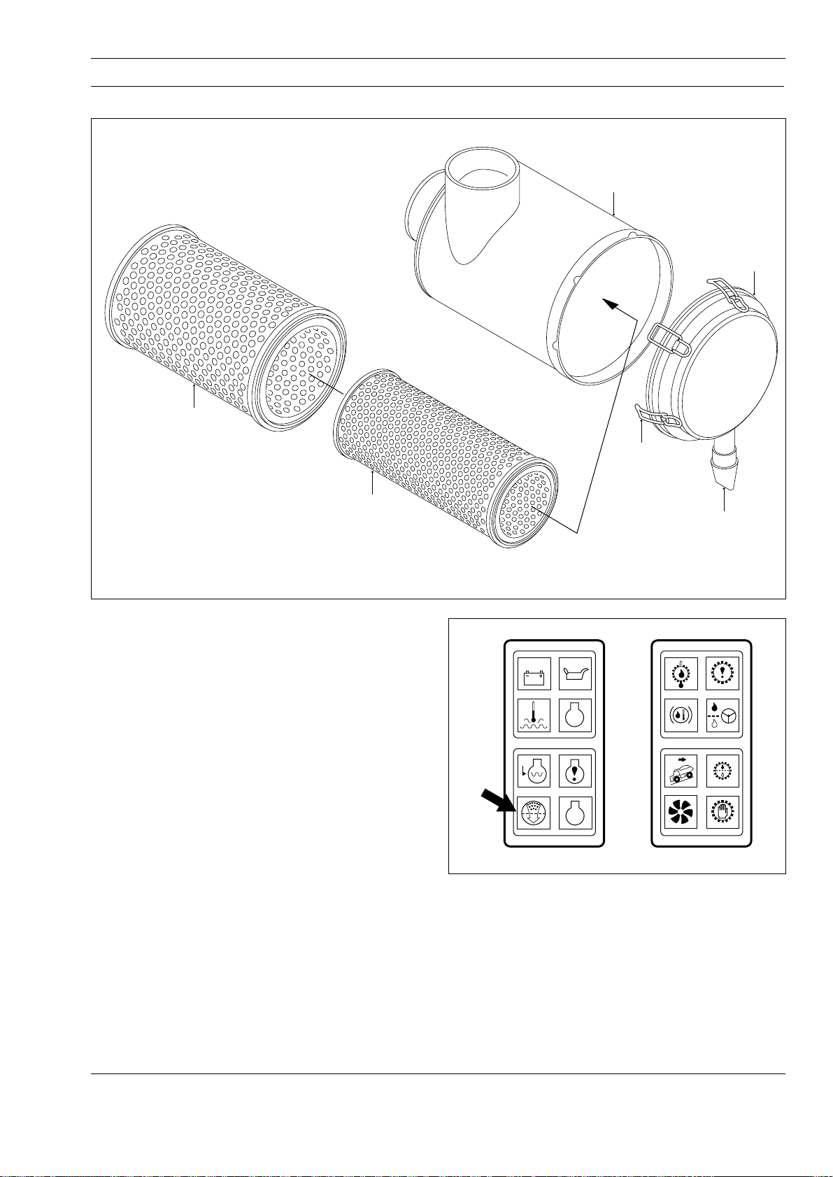
ENGINE - Air Cleaner
Section 110-0050
SM - 1532
1
4
2
5
1 - Air Cleaner Body
2 - Primary Element
3 - Safety Element
4 - Cover Assembly
5 - Latch
6 - Vacuator Valve
3
Fig. 1 - Exploded View of Air Cleaner
DESCRIPTION
Numbers in parentheses refer to Fig. 1, unless
otherwise specified.
There are two, dual dry element type air cleaner
assemblies mounted on the platform to the right hand
side of the cab. Air cleaner assemblies prolong engine
life by removing grit, dust and water from the air as it
enters the engine. Grit and dust combined with engine
oil, forms a highly abrasive compound which can destroy
the engine in a comparatively short period of time.
A rubber vacuator valve (6) attached to cover
assembly (4) in a downward position, ejects grit, dust
and water while the engine is running. Vacuator valve
(6) minimizes the need for daily servicing. Even
though vacuator valve (6) is normally under a slight
vacuum when the engine is running, pulsing of the
vacuum opens and closes vacuator valve (6) expelling
grit, dust and water as they collect. When the engine is
stopped, vacuator valve (6) opens and expels any
accumulated grit, dust or water.
6
SM - 1964
STOP
Fig. 2 - Air Cleaner Restriction Indicator Light
the circuit closes and a restriction indicator light in
the dash panel (Fig. 2) illuminates. This light shows
at a glance when the system air flow is being
restricted indicating that primary element (2) should
be serviced. Air restriction gauge (14, Fig. 3) automatically
resets after each air cleaner assembly is serviced.
An electrical air restriction gauge (14, Fig. 3) indicates
when air restriction levels reach the maximum
allowable limit. When air restriction levels are reached,
SM 1572 12-98
While the indicator light indicates the need for
servicing, it does not give as precise a measurement
as a water manometer or vacuum gauge. Refer to
1
Page 40
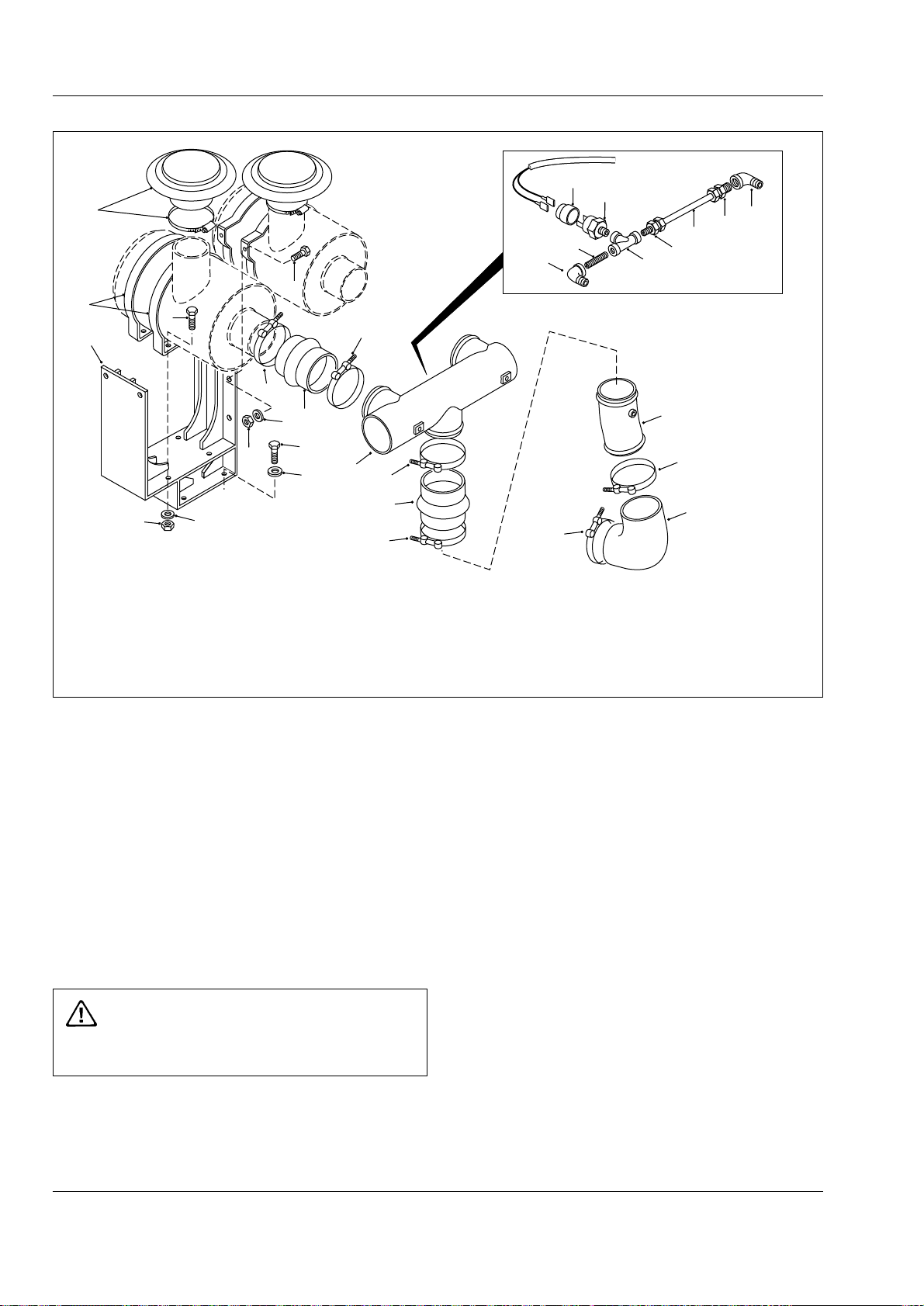
Engine - Air Cleaner
Section 110-0050
7
6
4
13
5
SM - 1701
15
14
22
17
19
22
4
10
9
8
3
1
12
2
10
18
17
16
20
10
21
5
1 - Bolt
2 - Hardened Washer
3 - Hardened Washer
4 - Bolt
5 - Locknut
6 - Mounting Band
3
10
7 - Cap Assembly
8 - Hump Hose
9 - Clamp
10 - Clamp
11 - Elbow
Fig. 3 - Exploded View of Air Cleaner Mounting
'Measuring Air Restriction'.
Safety element (3) is installed in each air cleaner
assembly inside of primary element (2). This element
increases the reliability of the air cleaner’s protection
of the engine from airborne dirt. It protects the engine
from dirt admitted by a damaged primary element (2),
or dirt that might be dropped into the air cleaner
assembly while servicing primary element (2).
MAINTENANCE
Numbers in parentheses refer to Fig. 1, unless
otherwise specified.
WARNING
Always shutdown the engine before servicing
air cleaner.
11
10
12 - Tube Assembly
13 - Bracket Assembly
14 - Air Restriction Gauge
15 - Protective Cap
16 - Tee
17 - Adaptor
18 - Nylon Tube
19 - Nipple
20 - Tube
21 - Hump Hose
22 - Elbow
over service. When restriction readings finally indicate
a change, remove primary element (2) carefully and
clean/replace as required. Refer to 'Primary Element'.
Never attempt to clean safety element (3). Change
safety element (3) after every third primary element (2)
service.
Make sure vacuator valve (6) is not damaged or
plugged and that the joint with cover assembly (4) is
not broken. If vacuator valve (6) is lost or damaged,
replace it to maintain pre-cleaner efficiency and normal
filter element service life.
Check condition of clamps (9 & 10, Fig. 3), hump
hoses (8 & 21, Fig. 3), elbow (11, Fig. 3), tube
assembly (12, Fig. 3) and tube (20, Fig. 3). Tighten/
replace as necessary.
The air cleaner elements should be serviced only
when the maximum allowable restriction has been
reached, as indicated by air cleaner restriction
indicator light. The elements should not be serviced on
the basis of visual observation as this would lead to
2
Air Cleaner Assembly
Numbers in parentheses refer to Fig. 1, unless
otherwise specified.
Note: Air cleaner body (1) should be thoroughly
SM 1572 12-98
Page 41

Engine - Air Cleaner
Section 110-0050
cleaned twice a year. Do not apply heat in any form to
air cleaner body (1).
1. Release latches (5) on cover assembly (4) and
remove cover assembly from air cleaner body (1).
2. Remove primary element (2) and safety element (3)
from air cleaner body (1).
3. Slacken clamps (9, Fig. 3) and disconnect hump
hose (8, Fig. 3) from air cleaner body (1).
4. Remove locknuts (5, Fig. 3), hardened washers
(3, Fig. 3) and bolts (4, Fig. 3) securing the air cleaner
assembly to the platform.
5. Remove the air cleaner assembly from the platform
for cleaning.
6. Open clamps (6) and remove from air cleaner
body (1). Open clamp on cap assembly (7) and
remove cap assembly from air cleaner body (1).
7. Blank off air cleaner body (1) outlets with tape or
cardboard. Reach inside body with a compressed air
nozzle or brush and remove dust from the body.
8. Remove all loose dust from air cleaner body (1) and
remove tape or cardboard from body outlets.
Note: Assembly and installation of the air cleaner
assembly is the reverse of disassembly and removal.
2. Remove primary element (2) from air cleaner body (1).
3. Using a damp cloth and a suitable solvent, wipe out
all excess dust from air cleaner body (1) and allow to
dry.
4. If the major contaminant on primary element (2) is
light dust, direct a jet of compressed air, not exceeding
6.9 bar (100 lbf/in2), against the pleats of the element.
The air jet should be directed in the opposite direction
of normal operating air flow. Move the air jet up and
down the pleats, holding the air nozzle 25 mm (1.0 in)
away from the pleats, to prevent rupturing the element
with either the nozzle or air jet.
5. In cases where the dust cake on primary element
(2) contains oil or carbon, air will not clean effectively.
Using manufacturers recommended solution and
warm water, not exceeding 48° C (120° F), soak
primary element (2) for fifteen minutes. Element
should be gently agitated to assist cleaning process.
Note: It is possible to modify an old agitator type
washing machine for primary element (2) cleaning. Do
not soak or agitate primary element (2) in the solution
for more than fifteen minutes. Prolonged exposure
softens vertical seams in the element.
6. Rinse washed element thoroughly with a low
pressure stream of water, not exceeding 0.7 bar
(10 lbf/in2), opposite from the normal air flow, until
rinse water runs clear.
Primary Element
Numbers in parentheses refer to Fig. 1.
Although a paper primary element (2) is used, it is
possible to clean it so that it can be reused. The
number of times one element can be reused depends
on the type of dirt on the element and the care
exercised in cleaning.
The life of a properly cleaned element will be
approximately as long as that of a new element for the
first one or two cleanings. After that, the life of the
element will gradually decrease with each cleaning;
however, it should perform satisfactorily through
approximately six cleanings, providing it does not rupture.
Visually determine the condition of primary element (2)
and choose either the compressed air or washing
method.
1. Release latches (5) on cover assembly (4) and
remove cover assembly from air cleaner body (1).
SM 1572 12-98
7. Air dry primary element (2) thoroughly before
returning it to service. Drying is a slow process which
may be hastened by exposing element to slowly
circulating heated air. Heated air temperature should
not exceed 46o C (115o F). Drying time can be reduced
to about three hours with heated air. DO NOT use a
light bulb for drying. DO NOT use compressed air on a
wet element.
Note: Replace paper elements after six cleanings or
two years in service, whichever comes first. Mark each
cleaned element to show total cleanings to date.
8. After primary element (2) is thoroughly dried,
inspect for damage or ruptures, especially close to the
end caps. To detect paper ruptures, place a bright light
bulb inside the element and rotate element slowly.
Inspection of element on the outside will disclose any
holes where concentrated light shines through. Even
the smallest hole will pass dust to the engine and may
result in costly engine repairs.
9. Install primary element (2) in air cleaner body (1).
3
Page 42

Engine - Air Cleaner
Section 110-0050
10. Install cover assembly (4) on air cleaner body (1)
and secure with latches (5).
Secondary Element
Numbers in parentheses refer to Fig. 1.
Since safety element (3) is protected from
contamination by primary element (2), it needs no
periodic cleaning and should be replaced only after
every third primary element (2) service.
1. With primary element (2) removed from air cleaner
body (1), remove safety element (3).
2. Remove any dust dislodged into air cleaner body (1)
outlet and, using a damp cloth and a suitable solvent,
wipe out all excess dust from air cleaner body (1) and
allow to dry.
3. Install new safety element (3) followed by primary
element (2) in air cleaner body (1)
4. Install cover assembly (4) on air cleaner body (1)
and secure with latches (5).
Recommendations
Numbers in parentheses refer to Fig. 3.
1. Under no condition should the vehicle be operated
without both filter elements in each air cleaner
assembly.
2. It is very important that hump hoses (8 & 21), tube
assembly (12), tube (20) and elbow (11) from the air
cleaner assembly to the engine be airtight or the
purpose of the air cleaner will be completely defeated.
All clamps (9 & 10) should be checked frequently and
tightened to prevent leaks.
(air cleaner outlet) increases. This vacuum is generally
measured as 'restriction in mm (inches) of water'.
The recommended maximum allowable intake
restrictions at rated speed and load are as follows:
a. 380 mm-H2O (15 in-H2O) with clean filter elements.
b. 635 mm-H2O (25 in-H2O) with dirty filter elements.
While the air restriction gauge sends a signal to
indicate the need for servicing, it does not give as
precise a measurement as a water manometer or
vacuum gauge.
Water Manometer
a. Remove protective cap (15) and disconnect
harness at air restriction gauge (14). Remove air
restriction gauge (14) from tee (16).
b. Hold water manometer vertically and fill both legs
approximately half full of water. Connect one of the
upper ends to tee (16) by means of a flexible hose.
c. With the manometer held vertically and the engine
drawing maximum air, the difference in height of the
water columns in the two legs is measured as the air
cleaner restriction.
d. If the restriction exceeds the levels indicated,
engine performance will be affected. Primary filter
element should be cleaned or replaced.
Vacuum Gauge
a. Remove protective cap (15) and disconnect
harness at air restriction gauge (14). Remove air
restriction gauge (14) from tee (16).
b. Connect the hose from the vacuum gauge to
tee (16) and, with the engine drawing maximum air,
take a note of the reading on the gauge.
3. Keep new or cleaned filter elements on hand for
replacement to prevent unnecessary downtime of the
vehicle.
MEASURING AIR RESTRICTION
Numbers in parentheses refer to Fig. 3.
As a dry air cleaner element becomes loaded with
dust, the vacuum on the engine side of the air cleaner
* * * *
4
c. If the restriction exceeds the levels indicated, engine
performance will be affected. Primary filter element
should be cleaned or replaced.
SERVICE TOOLS
Refer to Section 300-0070, SERVICE TOOLS for part
numbers of service tools referenced in this section and
general service tools required. These tools are
available from your dealer.
SM 1572 12-98
Page 43
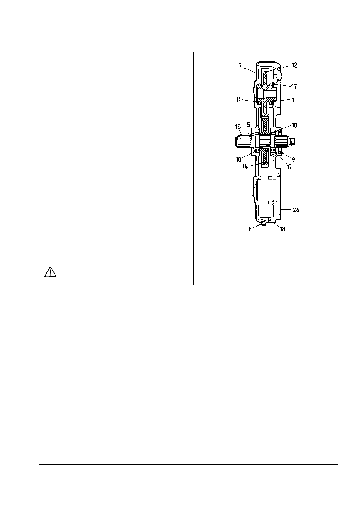
ENGINE - Power Takeoff
Section 110-0130
DESCRIPTION AND OPERATION
Numbers in parentheses refer to Fig. 1.
The function of the power takeoff (PTO), as the name
implies, is to provide the means of mounting and
driving an auxiliary component. The tandem pump for
the body hoist system and disc brake cooling system
is mounted to PTO cover (26) and its input shaft is
meshed with the internal splines in the hub of driven
gear (12). Refer to Section 230-0050, TANDEM
PUMP.
The major components of the PTO assembly are;
flywheel cover case (1), PTO cover (26), driveshaft (15),
drive gear (14) and driven gear (12).
As driveshaft (15) is driven by the engine crankcase,
drive gear (14) turns to drive driven gear (12). The
tandem pump driveshaft, meshed in the hub of driven
gear (12), turns with driven gear (12) to operate the
tandem pump which, in turn, supplies hydraulic oil to
the body hoist system and cooling oil to the disc
brake assemblies. Refer to Section 230-0050,
TANDEM PUMP.
SM - 1361
REMOVAL
Numbers in parentheses refer to Fig. 2.
WARNING
To prevent personal injury and property damage,
be sure wheel blocks, blocking materials and
lifting equipment are properly secured and of
adequate capacity to do the job safely.
1. Position the vehicle in a level work area, apply the
parking brake and switch off the engine.
2. Turn the steering wheel in both directions to relieve
pressure in the steering system. Block all road
wheels.
3. Disconnect driveline from yoke (22) at the PTO
assembly. Refer to Section 130-0010, FRONT
DRIVELINE.
4. Drain oil from power takeoff housing by removing
drain plug (6) from flywheel cover case (1). Reinstall
drain plug (6) securely.
1 - Flywheel Cover Case
5 - Oil Seal
6 - Plug
9 - Oil Seal
10 - Bearing
11 - Bearing
Fig. 1 - Cutaway View of Power Takeoff Assembly
12 - Driven Gear
14 - Drive Gear
15 - Driveshaft
17 - Snap Ring
18 - Gasket
26 - PTO Cover
the pump before loosening attaching nuts. Remove
nuts and lockwashers from pump mounting studs and
secure pump clear of the PTO assembly.
7. Match mark engine flywheel housing and flywheel
cover case (1) so that the PTO assembly can be
installed in the same position at 'Installation'.
8. Attach a suitable lifting device to the PTO
assembly and remove bolts (23 & 25) and
lockwashers (24) securing PTO assembly to the
engine flywheel housing. Carefully lower PTO
assembly and spacer (27) from the flywheel housing
and move to a clean work area for disassembly.
9. Remove spacer (27) from the PTO assembly.
5. Match mark tandem pump mounting flange and
PTO cover (26) so that the pump can be installed in
the same position at installation.
6. With suitable blocking or lifting equipment, support
SM 1573 Rev 1 1-00
DISASSEMBLY
Numbers in parentheses refer to Fig. 2.
1. Remove locknut (16) and hardened washer (19)
from driveshaft (15). Pull yoke (22) from driveshaft (15).
1
Page 44
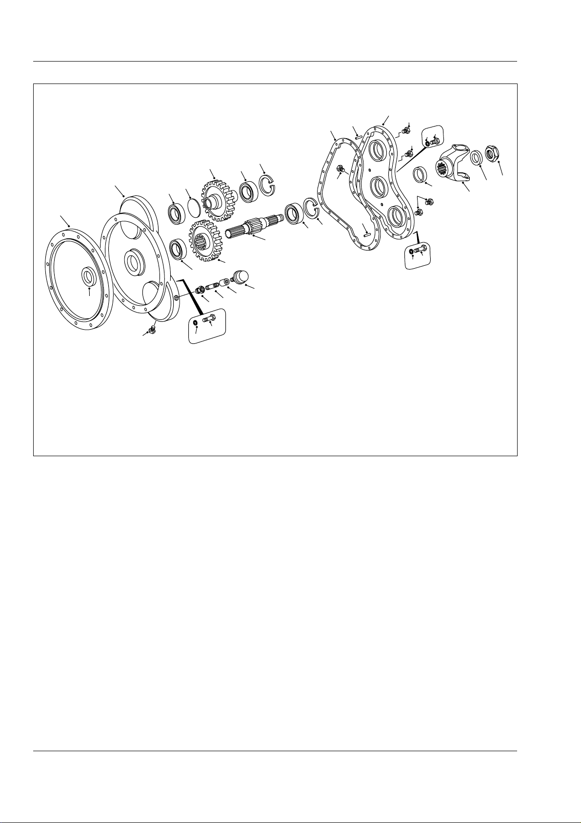
Engine - Power Takeoff
Section 110-0130
18
SM - 2399
26
2
30
3
4
6
1
27
5
1 - Flywheel Cover Case
2 - Dowel Pin
3 - Bolt
4 - Lockwasher
5 - Oil Seal
6 - Plug
7 - Bolt
14
11
28
17
21
15
6
2
17
10
15 - Driveshaft
16 - Locknut
17 - Snap Ring
18 - Gasket
19 - Hardened Washer
20 - Breather
21 - Breather Cap
22 - Yoke
9
6
7
8
23 - Bolt
24 - Lockwasher
25 - Bolt
26 - PTO Cover
27 - Spacer
28 - Coupling
29 - Adaptor
30 - Plug
22
19
16
12
13
11
10
20
29
6
25,23
24
8 - Lockwasher
9 - Oil Seal
10 - Bearing
11 - Bearing
12 - Driven Gear
13 - Plug
14 - Drive Gear
Fig. 2 - Exploded View of Power Takeoff Assembly
2. Remove bolts (3 & 7) and lockwashers (4 & 8) from
PTO cover (26). Pull PTO cover (26) and gasket (18)
from flywheel cover case (1). Discard gasket (18).
3. Place PTO cover (26) yoke side up on a work
bench. Pry oil seal (9) from PTO cover (26) and
discard.
4. Remove snap rings (17) from pump and driveshaft
bores. Drive bearings (10 & 11) from PTO cover (26)
with a sleeve or soft steel drift. Drive on the outer
race of bearings (10 & 11) taking care not to damage
the bearings.
5. Slide drive gear (14) from driveshaft (15) and pull
driven gear (12) from flywheel cover case (1).
6. Pull driveshaft (15) from flywheel cover case (1).
Pry oil seal (5) from flywheel cover case (1).
7. Pull bearings (10 & 11) from flywheel cover case
(1) with a suitable bearing puller.
8. If necessary, note locations and remove dowel pins
(2) from flywheel cover case (1) and breather
assembly (20, 21, 28 & 29) from PTO cover (26).
INSPECTION
Numbers in parentheses refer to Fig. 2.
1. Wash all parts thoroughly in a suitable solvent and
dry all but bearings (10 & 11) with compressed air.
Dry bearings (10 & 11) with a clean lint free cloth.
2. Check the condition of splines and teeth on gears
(12 & 14), driveshaft (15) and yoke (22) for burrs or
signs of wear.
3. Lubricate bearings (10 & 11) with oil and check
operation by spinning bearings by hand. DO NOT spin
bearings with compressed air. Inspect bearing bores
for out of roundness. Replace bearings, if required.
4. Inspect flywheel cover case (1) and PTO cover
(26) for cracks. If either flywheel cover case (1) or
2
SM 1573 Rev 1 1-00
Page 45
Engine - Power Takeoff
Section 110-0130
PTO cover (26) are damaged, both parts must be
replaced as an assembly.
5. Visually check oil seal lip contact surfaces on
driveshaft (15) and yoke (22) for nicks, dents,
scratches, wear, or corrosion. Replace as
necessary.
ASSEMBLY
Numbers in parentheses refer to Figs. 2.
Note: Prior to assembly, lubricate all seal lips and
surfaces with lubricant specified in Section 300-0020,
LUBRICATION SYSTEM.
Note: Tighten all fasteners without special torques
specified to standard torques listed in Section
300-0080, STANDARD BOLT AND NUT TORQUE
SPECIFICATIONS.
WARNING
To prevent personal injury and property
damage, be sure lifting device is properly
secured and of adequate capacity to do the job
safely.
1. If removed, install dowel pins (2) in flywheel cover
case (1) and breather assembly (20, 21, 28 & 29) in
PTO cover (26), as noted at disassembly.
2. Install new oil seal (5) in centre bore of flywheel
cover case (1) so that it is flush with flywheel cover
case (1) face. See Fig. 1.
Note: When installing new oil seals, install them with
the oil lip (larger of the two lips with the spring behind
it) facing inward. Care should be taken to prevent
damage to seal lips during assembly.
3. Press bearings (10 & 11) into their bores in
flywheel cover case (1).
4. Press bearings (10 & 11) into their respective
bores in PTO cover (26). Turn PTO cover (26) over
and install snap rings (17).
5. Install new oil seal (9) into centre bore in PTO
cover (26) so that it is flush with PTO cover (26)
face. See Fig. 1.
6. Install driven gear (12) and driveshaft (15) into
flywheel cover case (1). Slide drive gear (14) over
driveshaft (15) to its proper location.
7. Install new gasket (18) on PTO cover (26) and
assemble PTO cover (26) to flywheel cover case (1).
Secure PTO cover (26) to flywheel cover case (1)
with bolts (3 & 7) and lockwashers (4 & 8).
8. Install yoke (22), hardened washer (19) and
locknut (16) on driveshaft (15) end. Tighten locknut
(16) to a torque of 950 - 1 085 Nm (700 - 800 lbf ft).
INSTALLATION
Numbers in parentheses refer to Figs. 1 & 2.
Note: When reassembling PTO assembly to engine
flywheel housing, and tandem pump to PTO
assembly, be sure to align match marks inscribed
during disassembly.
Note: Tighten all fasteners without special torques
specified to standard torques listed in Section
300-0080, STANDARD BOLT AND NUT TORQUE
SPECIFICATIONS.
1. Install spacer (27) on PTO assembly and, using
suitable lifting equipment, position PTO assembly on
engine flywheel housing. Secure the PTO assembly
and spacer (27) to the engine flywheel housing with
bolts (23 & 25) and lockwashers (24).
2. Using suitable lifting equipment, position tandem
pump over its mounting studs and secure with nuts
and lockwashers removed during removal.
3. Reconnect driveline to yoke (22). Refer to Section
130-0010, FRONT DRIVELINE.
4. Remove oil level plug (6) from the front of PTO
cover (26) and fill PTO assembly with lubricant
specified in Section 300-0020, LUBRICATION
SYSTEM, until oil flows from the oil level port. Install oil
level plug (6) in PTO cover (26) and tighten securely.
5. Start the engine and bring oil to correct operating
temperature. Check for leaks and correct as necessary.
6. Remove wheel blocks from all road wheels.
SM 1573 Rev 1 1-00
3
Page 46
Engine - Power Takeoff
Section 110-0130
MAINTENANCE
Numbers in parentheses refer to Fig. 1.
Note: Refer to Section 300-0020, LUBRICATION
SYSTEM for recommended check and drain intervals
and lubricant specifications.
Oil Level Check
Remove oil level plug (6) from the front of PTO cover
(6) and, if oil level is below the bottom of the filler
hole, add lubricant until it flows from the filler hole.
Reinstall oil level plug (6) and tighten securely.
Drain and Refill
To drain: Remove drain plug (6) from flywheel cover
case (1) and drain oil into a suitable container.
Reinstall drain plug (6) securely when draining is
complete.
To refill: Remove oil level plug (6) from the front of
PTO cover (26) and fill PTO assembly with lubricant
specified in Section 300-0020, LUBRICATION
SYSTEM, until oil flows from the oil level port. Install oil
level plug (6) in PTO cover (26) and tighten securely.
SPECIAL TOOLS
There are no special tools required for procedures
outlined in this section. Refer to Section 300-0070,
SERVICE TOOLS, for part numbers of general service
tools required. These tools are available from your
dealer.
SPECIAL TORQUE SPECIFICATIONS
TORQUE
FIG. NO. ITEM NO. ITEM NAME Nm lbf ft
2 16 Locknut 950 - 1 085 700 - 800
* * * *
4
SM 1573 Rev 1 1-00
Page 47
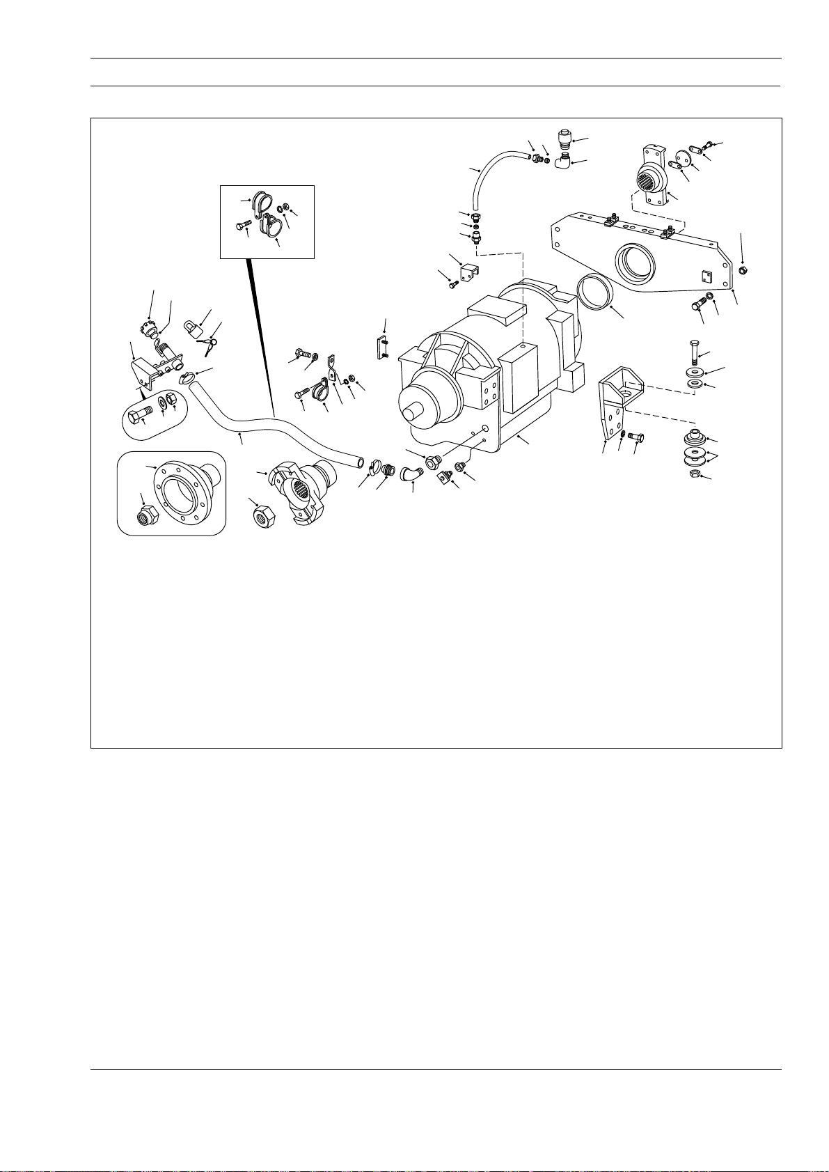
TRANSMISSION - Transmission and Mounting
Section 120-0010
13
14
25
51
50
*39
*38
1 - Transmission
2 - Trunnion
3 - Bolt
4 - Washer
5 - Locknut
6 - Bolt
7 - Hardened Washer
8 - Nut
9 - Mounting Bracket
10 - Bolt
11 - Lockwasher
12 - Isolation Mount
13 - Filler Cap
27
52
15
26
49
16
48
38
22
18
28
29
20
21
19
41
40
27 - Padlock
28 - Bolt
29 - Cover Plate
30 - Level Gauge
31 - Ring
32 - Bolt
33 - Strip
34 - Retainer
35 - Shim
36 - Shim
37 - Input Yoke
38 - Nut
*38 - Locknut
39 - Output Yoke
*39 - Output Flange
39
10
47
46
44
11
48
30
47
46
45
44
15
17
14 - Gasket
15 - Clamp
16 - Filler Hose
17 - Filler Tube
18 - Elbow
19 - Connector
20 - Nut
21 - Sleeve
22 - Nylon Tube
23 - Elbow
24 - Breather
25 - Adaptor
26 - Key
42
Fig. 1 - Exploded View of Transmission and Mounting
20
23
24
37
31
11
9
10
40 - Drain Cock
41 - Adaptor
42 - Adaptor
43 - Snubbing Washer
44 - P-clip
45 - Bracket
46 - Lockwasher
47 - Nut
48 - Bolt
49 - P-clip
50 - Bolt
51 - Hardened Washer
52 - Nut
* - Pre June 1998
Production
21
1
34
35,36
3
33
6
12
8
SM - 1965
32
4
7
12
43
5
2
DESCRIPTION
For transmission make, model and specification, refer
to Section 000-0000, GENERAL INFORMATION. For
transmission switches, sensors and instruments, refer
to Section 190-0270, SWITCHES AND SENSORS. For
transmission servicing and repair data, refer to the
transmission manufacturers service manual.
The transmission is remote mounted in the frame and
is supported by trunnion (2) assembly at the front and
two mounting brackets (9) at the rear.
Integral with transmission (1) assembly are torque
converter and planetary gearing. There are six forward
gears and two reverse gears with automatic lockup in
all speed ranges. Operation of the transmission is by
the Commercial Electronic Control (CEC) Shift System,
SM 1574 12-98
(previously known as ATEC).
A brief description and operation of the main
transmission components are as follows:
CEC Shift System
Refer to Section 120-0070, CEC SHIFT SYSTEM for
description and operation, wiring diagrams and
electrical troubleshooting of the CEC System.
Torque Converter
The torque converter consists of three elements pump, turbine, and stator. The pump is the input
element and is driven directly by the engine. The
turbine is the output element and is hydraulically
driven by the pump. The stator is the reaction (torque
multiplying) element.
1
Page 48
Transmission - Transmission and Mounting
Section 120-0010
When the pump turns faster than the turbine, the torque
converter is multiplying torque. When the turbine
approaches the speed of the pump the stator starts to
rotate with the pump and turbine. When this occurs,
torque multiplication stops and the torque converter
functions as a fluid coupling.
Lockup Clutch
The lockup clutch is located inside the torque converter
and consists of three elements - piston, clutch plate,
and backplate. The piston and backplate are driven by
the engine and the clutch plate, located between the
piston and backplate, is splined to the converter turbine.
The lockup clutch is hydraulically engaged and
released in response to electronic signals from the
ECU. It engages when the vehicle reaches a
predetermined speed. Engagement of the lockup clutch
provides a direct drive from the engine to the
transmission gearing. This eliminates converter
slippage to provide maximum fuel economy. The lockup
clutch releases at lower speeds (and momentarily
during shifts). When the lockup clutch is released, drive
from the engine is transmitted hydraulically through the
converter to the transmission gearing. The lockup
clutch also releases when the ECU detects certain
undesirable conditions.
Planetary Gears and Clutches
A series of planetary gears and shafts provide the gear
ratios and directions of travel for the vehicle. Power flow
through the planetaries is controlled by multiple clutch
packs. The clutches are applied and released
hydraulically in response to electronic signals from the
ECU.
Hydraulic Retarder
A vaned rotor and two vaned stators are the basic
components of the retarder. Application of the retarder
control valve fills the cavity around the rotor with oil
when the vehicle must be slowed on steep
downgrades. When the cavity is emptied, the rotor is
free of drag. Refer to Section 250-0130, RETARDER
CONTROL VALVE.
Maximum retarder effect occurs in the lowest gear
range with foot off of the accelerator pedal. Long
continuous use of the retarder will raise transmission
oil temperature. Short periods of full release, to interrupt
continuous application, will help prevent overheating.
During normal operation the dash mounted
transmission oil temperature gauge should read in the
green zone. However, during transmission retarder
operation oil temperature can enter the yellow 'Retarder
On' zone but should not enter the red zone.
Transmission Oil Cooler
The transmission oil is cooled by a separate oil cooler
mounted between the radiator and transmission to
maintain transmission oil within its required operating
temperature range. Refer to Section 210-0060,
TRANSMISSION OIL COOLER.
Transmission Oil Filter
The transmission oil filter is mounted off the frame at
the front right hand side of the transmission. It is
installed in the transmission oil lines to remove dirt
and other contaminants from the transmission oil to
minimise wear and provide maximum service life for
the transmission. Refer to Section 120-0100,
TRANSMISSION OIL FILTER.
REMOVAL
Numbers in parentheses refer to Fig. 1.
Note: Tag all lines, pipes, electrical connections and
mechanical linkages disconnected during removal to
aid in installation.
WARNINGS
To prevent personal injury and property
damage, be sure wheel chocks, blocking
materials and lifting equipment are properly
secured and of adequate capacity to do the job
safely.
High electrical current can cause sparks
and personal injury from burns. Switch circuit
breakers to the 'Off' position before removing
any electrical components. Remove battery
ground cable first, and reconnect last, to
prevent damaging electrical components.
Any time the battery equalizer is
disconnected from the batteries, remove
ground cable first, and reconnect last, to
prevent damaging the component.
1. Position the vehicle in a level work area, raise the
body and install the body prop pins. Refer to
Section 270-0010, BODY AND MOUNTING.
2. Apply the parking brake and switch off the engine.
Turn steering wheel several times to relieve pressure
in the steering circuit. Depress and release brake
pedal continuously to relieve pressure in the braking
system (pressure in accumulator hydraulic line
should be zero).
3. Block all road wheels.
2
SM 1574 12-98
Page 49

Transmission - Transmission and Mounting
Section 120-0010
Note: It is important that the electrical connections are
removed in the order listed in step 4 to prevent
damage to the electrical components.
4. Disconnect battery equalizer ground connection
from the batteries. Disconnect battery cables from
terminal posts (ground cable first). Disconnect
battery equalizer positive connection. Disconnect
electrical connections at the ECU.
5. Using suitable lifting equipment, support
transmission guard and remove mounting hardware
securing the guard to the frame. Remove
transmission guard.
6. Disconnect driveline from input yoke (37) at the
front of transmission (1). Refer to Section 130-0010,
FRONT DRIVELINE.
7. Disconnect driveline from output yoke/flange (39) at
the rear of transmission (1). Refer to Section
130-0020, REAR DRIVELINE.
8. Place a suitable container under drain cock (40),
loosen drain cock and drain oil from transmission (1).
After draining, tighten drain cock (40) securely.
9. Disconnect the transmission retarder linkage at
transmission (1).
10. Place a suitable container under the steering tank
drain plug, remove drain plug and drain the oil from
the steering tank. After draining, reinstall drain plug.
11. Disconnect steering lines from the steering pump
and remove mounting hardware securing steering
lines to transmission (1). Cap all open line ends and
steering pump fittings to prevent entry of dirt.
12. Disconnect transmission oil cooler lines and oil
filter lines from transmission (1). Cap all open lines
and fittings to prevent entry of dirt.
13. Disconnect hydraulic line from lockup drop out
valve at the front right hand side of transmission (1).
14. Disconnect all remaining hydraulic lines attached
to transmission (1). Cap all open lines and fittings to
prevent entry of dirt.
15. Disconnect all electrical connections and cables
attached to transmission (1).
transmission (1) and move bracket and valve clear of
the transmission (1).
17. Remove mounting hardware supporting mounting
brackets for body hoist lines to the top of
transmission (1).
18. Remove mounting hardware securing kick-over
valve mounting bracket to the top of transmission (1).
19. Slacken nut (20) and move nut (20) and nylon
tube (22) assembly free from connector (19) in the
top of transmission (1).
20. Detach clamps (15) and remove filler hose (16)
from filler tube (17) and adaptor (25).
21. Install suitable lifting eyes into the holes provided
at the top of transmission (1) housing and secure a
suitable lifting device to the eyes. Take up slack in the
chain or cable.
22. Remove locknuts (5), bolts (3) and washers (4)
securing trunnion (2) to the frame.
23. Remove bolts (6), hardened washers (7), snubbing
washers (43) and nuts (8) securing mounting brackets
(9) to frame.
24. Check to make certain that all hydraulic lines and
electrical connections fitted to transmission (1) have
been disconnected before moving transmission (1).
25. Carefully manoeuvre transmission (1) out of the
frame mounting and lower onto a suitable dolly or pallet.
26. Move transmission (1) assembly to a suitable
work area or onto a work stand for further
disassembly, if necessary.
DISASSEMBLY
Numbers in parentheses refer to Fig. 1.
Note: Refer to the transmission manufacturers
Service Manual if transmission service or repair is
required.
1. Remove bolts (32), strip (33), retainer (34) and
shims (35 & 36) securing input yoke (37) on
transmission (1). Pull input yoke (37) from
transmission (1).
16. Remove mounting hardware securing accumulator
valve mounting bracket to the front left hand side of
SM 1574 12-98
2. Pull trunnion (2) assembly from transmission (1)
and remove ring (31) from trunnion (2), if required.
3
Page 50
Transmission - Transmission and Mounting
Section 120-0010
3. Remove nut/locknut (38) securing output yoke/
flange (39) on transmission (1). Pull output yoke/flange
(39) from transmission (1).
4. Remove bolts (10) and lockwashers (11) securing
mounting brackets (9) to transmission (1). Remove
mounting brackets (9).
5. If necessary, remove isolation mounts (12) from
mounting brackets (9).
ASSEMBLY
Numbers in parentheses refer to Fig. 1.
Note: Tighten all fasteners without special torques
specified to standard torques listed in Section
300-0080, STANDARD BOLT AND NUT TORQUE
SPECIFICATIONS.
1. Secure mounting brackets (9) to transmission (1)
assembly with bolts (10) and lockwashers (11).
Tighten bolts (10) to a torque of 156 Nm (115 lbf ft). If
removed, install isolation mounts (12) to mounting
brackets (9).
2. If removed, fit new ring (31) to trunnion (2) and mount
trunnion (2) to the front of transmission (1) with small leg
to the top and facing away from transmission (1).
3. Make sure that transmission input shaft is in its
most outward position and the bearing is seated
against the shaft shoulder.
4. Coat input shaft splines and lip of oil seal with a thin
layer of EP, NLGI molybdenum grease. Install input
yoke (37) on input shaft by tapping lightly until the
yoke is seated. If input yoke (37) is a tight fit, heat
input flange (37) to 121° C (250° F) maximum prior to
assembly. Two methods which may be employed are:
a. Heat in controlled temperature furnace for a
minimum period of 45 minutes.
b. Submerge flange in heated oil for 15 minutes.
5. Use proper combination of shims (35 & 36) to obtain
a 0.2 - 0.3 mm (0.008 - 0.012 in) gap between retainer
face of input yoke (37) and end of input shaft. Fit
retainer (34) and secure with bolts (32) and strip (33).
Tighten bolts (32) to a torque of 130 - 156 Nm
(96 - 115 lbf ft).
6. Coat output shaft splines and threads, and lip of oil
seal with a thin layer of EP, NLGI molybdenum
grease. Install output yoke/flange (39) on output shaft
by tapping lightly until the yoke is seated. If output
yoke/flange (39) is a tight fit, heat output yoke/flange
(39) to 121° C (250° F) maximum prior to assembly,
using either of the methods described in step 3.
7. Secure output yoke/flange (39) on output shaft with
nut/locknut (38). Tighten nut (38) to a torque of
950 - 1 355 Nm (700 - 1 000 lbf ft).
8. After assembly has cooled, check torque of bolts
(32) and nut/locknut (38) and retighten to their required
torques.
INSTALLATION
Numbers in parentheses refer to Fig. 1.
Note: Tighten all fasteners without special torques
specified to standard torques listed in Section
300-0080, STANDARD BOLT AND NUT TORQUE
SPECIFICATIONS.
WARNING
To prevent personal injury and property
damage, be sure wheel chocks, blocking
materials and lifting equipment are properly
secured and of adequate capacity to do the job
safely.
1. Position transmission (1) assembly under the
vehicle and attach a suitable lifting device to the eye
bolts on top of transmission (1).
2. Carefully lift transmission (1) assembly into its
mounting position and lightly secure trunnion (2) to the
frame (mounting face to the front of the frame
mounting brackets) with bolts (3), washers (4) and
locknuts (5). Install bolts (3) from the rear of the
assembly.
3. Install bolts (6), hardened washers (7), snubbing
washers (43) and nuts (8) securing mounting brackets
(9) to frame mounting brackets. Securely tighten bolts
(6) to a torque of 278 Nm (205 lbf ft).
4. Securely tighten bolts (3), securing trunnion (2) to
frame mounting brackets, to a torque of 156 Nm
(115 lbf ft).
5. Remove lifting device and lifting eye bolts from top
of transmission (1).
6. Install filler hose (16) to filler tube (17) and adaptor
(25) and secure with clamps (15).
4
SM 1574 12-98
Page 51
Transmission - Transmission and Mounting
Section 120-0010
7. Secure accumulator valve mounting bracket to the
front left hand side of transmission (1) assembly with
mounting hardware removed during removal.
8. Secure kick-over valve mounting bracket to top of
transmission (1) assembly with mounting hardware
removed during removal.
9. Secure body hoist lines mounting brackets to the
top of transmission (1) assembly with mounting
hardware removed during removal.
10. Connect all electrical connections and cables to
transmission (1) as tagged at removal.
11. Connect transmission oil cooler lines to
transmission (1) and oil filter lines to transmission oil
filter as tagged at removal.
12. Connect steering pump hydraulic lines as tagged
at removal and secure lines to transmission (1) with
mounting hardware removed during removal.
13. Connect hydraulic line from lockup drop out valve
to front right hand side of transmission (1).
14. Connect any remaining hydraulic lines which were
removed during removal. Ensure all hydraulic lines are
securely tightened.
Note: It is important that the electrical connections are
made in the order listed in step 21 to prevent damage
to the electrical components.
21. Connect electrical connections at the ECU.
Connect battery equalizer positive connection.
Connect battery cables to battery terminal posts
(ground cable last). Connect battery equalizer ground
connection.
22. Start the engine and make an operational check
while the engine is running of all lines and
connections disconnected during removal of
transmission (1). Check for leaks and tighten lines
and fittings as required.
23. Ensure parking brake is applied, remove the body
prop pins and lower the body. Refer to Section
270-0010, BODY AND MOUNTING. Remove wheel
chocks from all road wheels.
MAINTENANCE
Periodic Inspections
For easier inspection, the transmission should be kept
clean. Make periodic checks for loose bolts and
leaking oil lines. Check the condition of electrical
harnesses and connections regularly.
15. Connect transmission retarder linkage at
transmission (1).
16. Install rear driveline to output yoke/flange (39) at
the rear of transmission (1) and secure with mounting
hardware removed during removal. Refer to
Section 130-0020, REAR DRIVELINE.
17. Install front driveline to input yoke (37) at the front
of transmission (1) and secure with mounting
hardware removed during removal. Refer to
Section 130-0010, FRONT DRIVELINE.
18. Using suitable lifting equipment, support
transmission guard and secure guard to the frame with
mounting hardware removed during removal.
19. Fill transmission (1) assembly with oil specified in
Section 300-0020, LUBRICATION SYSTEM, and check
the oil level as described under 'Oil Level Check'.
20. Fill steering tank with oil specified in Section
300-0020, LUBRICATION SYSTEM, and check the oil
level as described in Section 220-0040, STEERING
AND BRAKE CONTROL TANK.
The transmission breather should be checked
regularly and as frequently as necessary, depending
on the operating conditions of the vehicle. A badly
corroded or plugged breather restricts proper
breathing and causes a buildup of condensation and
subsequent oil deterioration.
Oil Level Check
WARNING
When checking the oil level, be sure that the
parking brake is applied and all road wheels
are securely blocked.
Check the transmission oil level and add oil if low,
every 10 hours/daily. Use only oil of the type
specified in Section 300-0020, LUBRICATION
SYSTEM.
Because the transmission oil cools, lubricates and
transmits hydraulic power it is important that the
proper oil level be maintained at all times. If the oil
level is too low, the converter and clutches will not
receive an adequate supply of oil. If the oil level is too
SM 1574 12-98
5
Page 52
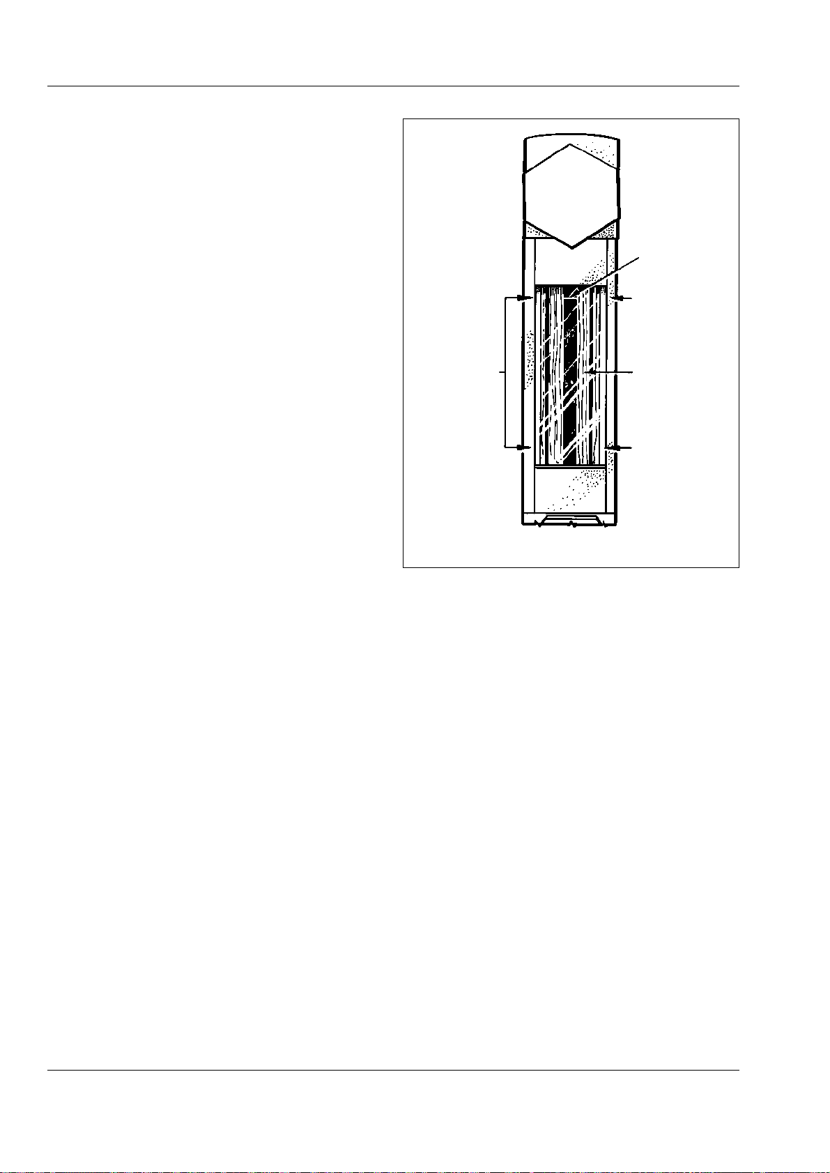
Transmission - Transmission and Mounting
Section 120-0010
high, the oil will aerate and the transmission will
overheat. It is absolutely necessary that the oil put into
the transmission be clean.
Oil must be handled in clean containers to prevent
foreign material from entering the system.
Note: Containers or fillers that have been used for
antifreeze or engine coolant solution must not be
used for transmission oil.
Visual Level Indicator
A visual level indicator is mounted on the lower left
side of the transmission main housing and provides a
method of checking the oil level. Refer to Fig. 2.
Cold Oil Level Check
Before starting the engine, check the visual level
indicator or remove the ADD (lower) plug. If oil is
present in the indicator or if oil flows from the plug
opening, the transmission has sufficient oil to permit
safe starting of the engine. If no oil is present, add
sufficient oil to bring the level within the indicator or
to cause a flow from the plug opening. Replace the
plug.
SAFE
OPERATIONAL
LEVEL AREA
SM - 1250
RED LINE
NO RED
LINE VISIBLE
(OVERFILL)
FULL MARK
(CENTRE)
NO OIL VISIBLE
(UNDERFILL)
Hot Oil Level Check
Note: Observe the condition of the oil in the visual
level indicator or the type of flow from the plug
opening. Foaming or spurting may indicate a false
level.
A hot oil level check is made to determine if there is
sufficient oil for working operation of the
transmission. Select neutral on the transmission
range selector and start the engine. Operate the
vehicle until the transmission reaches a normal
operating temperature of 82 - 103° C (180 - 220° F).
Idle the engine, apply the parking brake and block all
road wheels.
Check the visual level indicator or remove the FULL
(upper) oil level check plug. The oil should be within
the indicator limits shown in Fig. 2 or at or near the
level of the plug opening. Add or drain oil as
necessary to bring the oil level within these limits.
Note: The transmission may be operated safely as
long as the oil level is above the ADD (lower) plug.
Oil and Filter Change
After the first 150 hours of operating a new or rebuilt
transmission, the transmission oil and filters should
be changed.
Fig. 2 - Visual Level Indicator
The transmission oil and filters should be changed at
the intervals specified in Section 300-0020,
LUBRICATION SYSTEM, or sooner, depending on
operating conditions. Also, the oil must be changed
whenever there are traces of dirt or evidence of high
temperature indicated by discoloration or strong odour.
The screen and magnet assembly in the sump should
be removed and cleaned with mineral spirits at each
oil change. Metal particles in the oil (except for the
minute particles normally trapped in the oil filters)
indicate damage has occurred in the transmission
When these particles are found in the filters, the
cause must be established and rectified immediately
to prevent damage to the transmission.
At each oil change, examine the used oil for evidence
of dirt or water. A normal amount of condensation will
emulsify in the oil during operation of the
transmission. However, if there is evidence of water
or engine coolant in the oil, the cause must be
established and rectified immediately to prevent
damage to the transmission.
6
SM 1574 12-98
Page 53
Transmission - Transmission and Mounting
Welding on Vehicles Equipped With CEC
WARNINGS
The ECU can be damaged by improper welding
procedures.
Any time the battery equalizer is
disconnected from the batteries, remove
ground cable first, and reconnect last, to
prevent damaging the component.
When frame or other welding is required, the
following precautions are to be taken to protect the
electronic components.
a. Disconnect battery equalizer ground connection
from the batteries. Disconnect battery cables from
terminal posts (ground cable first). Disconnect
battery equalizer positive connection. Disconnect
electrical connections at the ECU.
b. If additional system ground wires are connected to
the frame, they must be disconnected also.
c. Cover electronic components and wiring to protect
from damage.
d. Do not connect welding cables to electronic
components. Do not weld on electronic components.
If welding is to be done close to electronic
components, the components should be removed
prior to the welding process.
e. On completion of all welding reconnect electrical
connections in the reverse order to step a.
TROUBLESHOOTING
Converter Stall Test
A stall test should be conducted when the power
package (engine and transmission) is not performing
satisfactorily. The purpose of the test is to determine
the engine power output and establish if the
transmission is the malfunctioning component.
Section 120-0010
WARNING
When conducting a stall test, the vehicle must
be positively prevented from moving. The
parking brake must be applied and the vehicle
should be blocked to prevent movement
forward or reverse. Keep people safely away
from the vehicle path. Do not maintain the
stalled condition longer than 30 seconds due
to rapid heating of the transmission oil. With
the transmission in neutral, run the engine at
1 200 - 1 500 rev/min for two minutes to cool
the oil between tests. Do not allow the
converter-out temperature to exceed 135° C
(275° F). Keep a close check to prevent
overheating of the engine cooling system.
1. Position the vehicle on a level area with room for
movement all round.
2. Apply the parking brake and block all road wheels.
Turn the manual mode key switch to the 'On' position
and the mode selection switch to the 'Power' mode.
3. Apply the service brake, release the parking brake
and select fifth gear on the transmission shift
selector. The transmission will shift to fifth gear and
deactivate the lockup clutch. Apply the parking brake
and release the foot pedal.
4. Accelerate the engine to full throttle and, using a
tachometer of known accuracy, note the maximum
rev/min the engine will attain. Converter-out pressure
should be 2 bar (30 lbf/in²).
Note: The stall speed of each vehicle is noted on the
final inspection records prior to the vehicle leaving
the factory. This can be used as a guide when
checking the stall speed. It is recommended to keep
a record of the stall speed after each major service
and use the previous recorded value as a guide.
5. When the stall check is complete, return the
accelerator to the idle position and move the shift
selector to the neutral position.
Note: Engine power will decrease with an increase in
elevation (altitude), becoming more pronounced at
greater elevation. This will result in a lower engine
speed under converter stall conditions.
SM 1574 12-98
7
Page 54
Transmission - Transmission and Mounting
Section 120-0010
6. During the stall check the transmission oil
temperature should rise while the engine is under
load and drop when the transmission is returned to
neutral. Should the temperature fail to drop it
indicates that there is a problem with the converter.
7. After making allowances for elevation, a low engine
speed may indicate the engine is not delivering full
power. Refer to engine service manual for engine
repair information.
Electronic Troubleshooting
Refer to Section 120-0070, CEC SHIFT SYSTEM for
general electrical troubleshooting. For more detailed
electrical troubleshooting refer to the Allison
Transmission Commercial Electronic Control (CEC)
Troubleshooting Manual SA2712A.
Mechanical Troubleshooting
It is recommended to follow the procedures laid down
for mechanical troubleshooting, as outlined in the
'Mechanical Trouble Shooting' charts, before carrying
out electrical troubleshooting procedures.
WARNING
Be sure to apply the parking brake, switch off
the engine and block all road wheels before
troubleshooting the vehicle. Should it be
necessary to run the engine, it is imperative
that an operator be present in the cab at all
times, even at idle.
SPECIAL TOOLS
There are no special tools required for the
procedures outlined in this section. Refer to Section
300-0070, SERVICE TOOLS for part numbers of
service tools which should be used in conjunction with
procedures outlined in the transmission manufacturers
service manual, and general service tools required.
These tools are available from your dealer.
MECHANICAL TROUBLESHOOTING CHART
CONDITION REASON REMEDY
A - Transmission overheats High or low oil level Restore proper oil level
Aerated (foaming) oil Refer to condition 'B'
Vehicle overloaded Reduce load
Engine coolant overheated Correct engine overheating
Transmission oil cooler or Clean or replace oil cooler or lines
lines kinked or clogged
Low coolant level Add coolant, check for leaks
Oil leaking Check transmission and lines for leaks
Low main pressure Refer to condition 'V'
Low converter-out pressure Refer to condition 'U'
Vehicle brakes dragging Check parking and service brakes
Torque converter stator locked Check for low top speed of vehicle. Check
torque converter components.
Clutch slipping Overhaul transmission. Replace worn piston
seal rings or clutch plates.
B - Oil is aerated (foaming) Incorrect type of oil used Change oil. Use only oil specified in Section
300-0020, LUBRICATION SYSTEM.
High or low oil level Restore proper oil level
Air entering suction side of Check oil pump bolts and gasket
oil pump
Water in oil Check for source, clean system
8
SM 1574 12-98
Page 55
Transmission - Transmission and Mounting
Section 120-0010
MECHANICAL TROUBLESHOOTING CHART
CONDITION REASON REMEDY
C - Heavy metal debris found Transmission internal failure Completely disassemble, clean and repair
in oil transmission. Replace filters and clean lines
and oil cooler.
D - Coolant found in oil Transmission oil cooler leaking Completely disassemble and thoroughly clean
transmission. Replace all friction faced clutch
plates. Repair or replace oil cooler. Replace
filters and clean external lines.
E - Transmission will not Loss of electrical power Refer to Electronic Troubleshooting
operate in any range
regardless of selector position
F - Transmission continues in Loss of electrical power Refer to Electronic Troubleshooting
the same forward gear
regardless of selector position
Internal mechanical failure Overhaul transmission
Driveline failure Check transmission input and output
Low oil level Restore proper oil level
Low main pressure Refer to condition 'V'
G - Shifting is erratic Refer to Electronic Troubleshooting
H - Transmission operates only Refer to Electronic Troubleshooting
in first, neutral and reverse
I - Transmission shifts to Refer to Electronic Troubleshooting
neutral during reverse
operation, but will operate
normally in all other ranges
J - Vehicle operates in reverse Reverse clutch has failed Overhaul transmission
and moves backwards in (won't release)
neutral when engine is
accelerated, but stalls in all
other gears when engine is
accelerated - Electronic
Troubleshooting OK
K - Vehicle operates in first First and second gear clutch Overhaul transmission
and second gears and moves failed (won't release)
forward in neutral when engine
is accelerated, but stalls in all
other gears when engine is
accelerated - Electronic
Troubleshooting OK
L - Vehicle operates in third Third and fourth gear clutch Overhaul transmission
and fourth gears and moves failed (won't release)
forward in neutral when engine
is accelerated, but stalls in all
other gears when engine is
accelerated - Electronic
Troubleshooting OK
SM 1574 12-98
9
Page 56
Transmission - Transmission and Mounting
Section 120-0010
MECHANICAL TROUBLESHOOTING CHART
CONDITION REASON REMEDY
M - Vehicle operates in fifth Fifth and sixth gear clutch Overhaul transmission
and sixth gears and moves failed (won't release)
forward in neutral when engine
is accelerated, but stalls in all
other gears when engine is
accelerated - Electronic
Troubleshooting OK
N - No power is transmitted in Range clutch failed (won't Overhaul transmission. Check for worn piston
any one range - Electronic apply, slipping) seals, broken piston housing, or worn clutch
Troubleshooting OK plates in that range.
O - Vehicle will operate in Splitter-overdrive clutch won't Overhaul transmission. Check splitter clutches
second, fourth, sixth and release or splitter-direct clutch for worn components.
reverse gears but will not won't apply, slipping
operate in all other gears Electronic Troubleshooting OK
P - Vehicle will operate in first, Splitter-direct clutch won't Overhaul transmission. Check splitter clutches
third and fifth gears but will not release or splitter-overdrive for worn components.
operate in all other gears - clutch won't apply, slipping
Electronic Troubleshooting OK
Q - Slow clutch engagement Low oil level Add oil to proper level
Foaming oil Refer to condition 'B'
Worn piston seals Overhaul transmission
Low main pressure Refer to condition 'V'
R - Vehicle lacks power and Engine malfunction Check engine. Refer to engine service manual.
acceleration
S - High engine speed at Low oil level Add oil to proper level
converter stall
Aerated oil Refer to condition 'B'
Low engine speed at converter Refer to condition 'T'
stall
High engine speed at Refer to condition 'S'
converter stall
Hydraulic retarder partially Check retarder linkage
applied
Vehicle brakes dragging Check parking and service brakes
Stator freewheel clutch failed Overhaul transmission
Low converter-out pressure Refer to condition 'U'
High oil temperature (above Refer to condition 'A'
135° C; 275° F)
10
Clutch slipping, main pressure Overhaul transmission. Replace clutch piston
normal seal rings or clutch plates.
Foaming oil Refer to condition 'B'
SM 1574 12-98
Page 57
Transmission - Transmission and Mounting
MECHANICAL TROUBLESHOOTING CHART
CONDITION REASON REMEDY
T - Low engine speed at Low engine output torque Tune engine and check output
converter stall
U - Low converter-out Low oil level Add oil to proper level
pressure
V - Low main pressure Low oil level Add oil to proper level
Converter element Check for noise at stall; overhaul converter if
interference necessary
Transmission oil not up to Warm up transmission to 82 - 103° C
operating temperature (180 - 220° F)
Oil line leakage (oil cooler or Check for leaks, correct as required
filter)
Plugged oil strainer Clean oil strainer
Defective oil pump Rebuild/replace oil pump assembly
High oil temperature Refer to condition 'A'
Foaming oil Refer to condition 'B'
Section 120-0010
Leaks in hydraulic system Check all external points for leaks; check each
range for localizing internal leaks
Failure in pressure regulator Overhaul valve assembly
Worn input oil pump assembly Rebuild/replace pump assembly
Clogged oil strainer Clean oil strainer
Air leaks at suction side of Check input pump, correct as required
input pump
W - Downshift of transmission Refer to Electronic Troubleshooting
is permitted during lockup
operation
X - Shift quadrant not Failed light bulb Replace the light bulb
illuminated
Y - Reverse signal not Refer to Electronic Troubleshooting
energized
SPECIAL TORQUE SPECIFICATIONS
TORQUE
FIG. NO. ITEM NO. ITEM NAME Nm lbf ft
1 3 Bolt 156 115
1 6 Bolt 278 205
1 10 Bolt 156 115
1 32 Bolt 130 - 156 96 - 115
1 38 Nut/Locknut 950 - 1 355 700 - 1 000
SM 1574 12-98
* * * *
11
Page 58

THIS PAGE IS INTENTIONALLY LEFT BLANK
Page 59
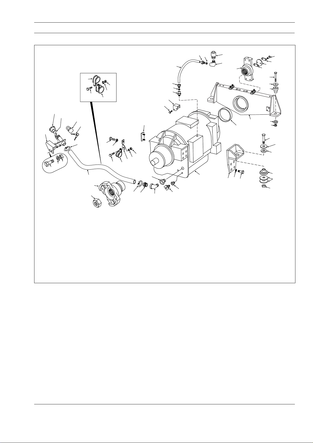
TRANSMISSION - Transmission and Mounting
Section 120-0010
13
14
25
52
51
50
1 - Transmission
2 - Trunnion
3 - Bolt
4 - Washer
5 - Locknut
6 - Bolt
7 - Hardened Washer
8 - Nut
9 - Mounting Bracket
10 - Bolt
11 - Lockwasher
12 - Isolation Mount
13 - Filler Cap
27
15
26
49
16
48
38
39
20
21
22
18
28
29
20
19
21
40
41
1
27 - Padlock
28 - Bolt
29 - Cover Plate
30 - Level Gauge
31 - Ring
32 - Bolt
33 - Strip
34 - Retainer
35 - Shim
36 - Shim
37 - Input Yoke
38 - Nut
39 - Output Yoke
10
47
46
44
11
48
30
47
46
45
44
15
17
14 - Gasket
15 - Clamp
16 - Filler Hose
17 - Filler Tube
18 - Elbow
19 - Connector
20 - Nut
21 - Sleeve
22 - Nylon Tube
23 - Elbow
24 - Breather
25 - Adaptor
26 - Key
42
Fig. 1 - Exploded View of Transmission and Mounting
23
24
37
2
31
11
9
10
40 - Drain Cock
41 - Adaptor
42 - Adaptor
43 - Snubbing Washer
44 - P-clip
45 - Bracket
46 - Lockwasher
47 - Nut
48 - Bolt
49 - P-clip
50 - Bolt
51 - Hardened Washer
52 - Nut
53 - Isolation Mount
34
35,36
3
4
53
53
5
SM - 2400
32
33
6
7
12
12
43
8
DESCRIPTION
For transmission make, model and specification, refer
to Section 000-0000, GENERAL INFORMATION. For
transmission switches, sensors and instruments, refer
to Section 190-0270, SWITCHES AND SENSORS. For
transmission servicing and repair data, refer to the
transmission manufacturers service manual.
The transmission is remote mounted in the frame and
is supported by trunnion (2) assembly at the front and
two mounting brackets (9) at the rear.
Integral with transmission (1) assembly are torque
converter and planetary gearing. There are six forward
gears and two reverse gears with automatic lockup in
all speed ranges. Operation of the transmission is by
the Commercial Electronic Control (CEC) Shift System,
SM 1905 1-00
(previously known as ATEC).
A brief description and operation of the main
transmission components are as follows:
CEC Shift System
Refer to Section 120-0070, CEC SHIFT SYSTEM for
description and operation, wiring diagrams and
electrical troubleshooting of the CEC System.
Torque Converter
The torque converter consists of three elements pump, turbine, and stator. The pump is the input
element and is driven directly by the engine. The
turbine is the output element and is hydraulically
driven by the pump. The stator is the reaction (torque
multiplying) element.
1
Page 60
Transmission - Transmission and Mounting
Section 120-0010
When the pump turns faster than the turbine, the
torque converter is multiplying torque. When the
turbine approaches the speed of the pump the stator
starts to rotate with the pump and turbine. When this
occurs, torque multiplication stops and the torque
converter functions as a fluid coupling.
Lockup Clutch
The lockup clutch is located inside the torque
converter and consists of three elements - piston,
clutch plate, and backplate. The piston and backplate
are driven by the engine and the clutch plate, located
between the piston and backplate, is splined to the
converter turbine.
The lockup clutch is hydraulically engaged and
released in response to electronic signals from the
ECU. It engages when the vehicle reaches a
predetermined speed. Engagement of the lockup
clutch provides a direct drive from the engine to the
transmission gearing. This eliminates converter
slippage to provide maximum fuel economy. The
lockup clutch releases at lower speeds (and
momentarily during shifts). When the lockup clutch is
released, drive from the engine is transmitted
hydraulically through the converter to the transmission
gearing. The lockup clutch also releases when the
ECU detects certain undesirable conditions.
Planetary Gears and Clutches
A series of planetary gears and shafts provide the gear
ratios and directions of travel for the vehicle. Power flow
through the planetaries is controlled by multiple clutch
packs. The clutches are applied and released hydraulically
in response to electronic signals from the ECU.
Hydraulic Retarder
A vaned rotor and two vaned stators are the basic
components of the retarder. Application of the retarder
control valve fills the cavity around the rotor with oil
when the vehicle must be slowed on steep
downgrades. When the cavity is emptied, the rotor is
free of drag. Refer to Section 250-0130, RETARDER
CONTROL VALVE.
Maximum retarder effect occurs in the lowest gear
range with foot off of the accelerator pedal. Long
continuous use of the retarder will raise transmission
oil temperature. Short periods of full release, to interrupt
continuous application, will help prevent overheating.
During normal operation the dash mounted
transmission oil temperature gauge should read in the
green zone. However, during transmission retarder
operation oil temperature can enter the yellow
'Retarder On' zone but should not enter the red zone.
Transmission Oil Cooler
The transmission oil is cooled by a separate oil cooler
mounted between the radiator and transmission to
maintain transmission oil within its required operating
temperature range. Refer to Section 210-0060,
TRANSMISSION OIL COOLER.
Transmission Oil Filter
The transmission oil filter is mounted off the frame at
the front right hand side of the transmission. It is
installed in the transmission oil lines to remove dirt and
other contaminants from the transmission oil to
minimise wear and provide maximum service life for
the transmission. Refer to Section 120-0100,
TRANSMISSION OIL FILTER.
REMOVAL
Numbers in parentheses refer to Fig. 1.
Note: Tag all lines, pipes, electrical connections and
mechanical linkages disconnected during removal to
aid in installation.
WARNINGS
To prevent personal injury and property
damage, be sure wheel chocks, blocking
materials and lifting equipment are properly
secured and of adequate capacity to do the job
safely.
High electrical current can cause sparks
and personal injury from burns. Switch circuit
breakers to the 'Off' position before removing
any electrical components. Remove battery
ground cable first, and reconnect last, to
prevent damaging electrical components.
Any time the battery equalizer is
disconnected from the batteries, remove
ground cable first, and reconnect last, to
prevent damaging the component.
1. Position the vehicle in a level work area, raise the
body and install the body prop pins. Refer to
Section 270-0010, BODY AND MOUNTING.
2. Apply the parking brake and switch off the engine.
Turn steering wheel several times to relieve pressure
in the steering circuit. Depress and release brake
pedal continuously to relieve pressure in the braking
system (pressure in accumulator hydraulic line should
be zero).
3. Block all road wheels.
2
SM 1905 1-00
Page 61

Transmission - Transmission and Mounting
Section 120-0010
Note: It is important that the electrical connections are
removed in the order listed in step 4 to prevent
damage to the electrical components.
4. Disconnect battery equalizer ground connection
from the batteries. Disconnect battery cables from
terminal posts (ground cable first). Disconnect battery
equalizer positive connection. Disconnect electrical
connections at the ECU.
5. Using suitable lifting equipment, support
transmission guard and remove mounting hardware
securing the guard to the frame. Remove transmission
guard.
6. Disconnect driveline from input yoke (37) at the
front of transmission (1). Refer to Section 130-0010,
FRONT DRIVELINE.
7. Disconnect driveline from output yoke (39) at the
rear of transmission (1). Refer to Section 130-0020,
REAR DRIVELINE.
8. Place a suitable container under drain cock (40),
loosen drain cock and drain oil from transmission (1).
After draining, tighten drain cock (40) securely.
9. Disconnect the transmission retarder linkage at
transmission (1).
10. Place a suitable container under the steering tank
drain plug, remove drain plug and drain the oil from the
steering tank. After draining, reinstall drain plug.
11. Disconnect steering lines from the steering pump
and remove mounting hardware securing steering
lines to transmission (1). Cap all open line ends and
steering pump fittings to prevent entry of dirt.
12. Disconnect transmission oil cooler lines and oil
filter lines from transmission (1). Cap all open lines
and fittings to prevent entry of dirt.
13. Disconnect hydraulic line from lockup drop out
valve at the front right hand side of transmission (1).
14. Disconnect all remaining hydraulic lines attached
to transmission (1). Cap all open lines and fittings to
prevent entry of dirt.
15. Disconnect all electrical connections and cables
attached to transmission (1).
transmission (1) and move bracket and valve clear of
the transmission (1).
17. Remove mounting hardware supporting mounting
brackets for body hoist lines to the top of
transmission (1).
18. Remove mounting hardware securing kick-over
valve mounting bracket to the top of transmission (1).
19. Slacken nut (20) and move nut (20) and nylon tube
(22) assembly free from connector (19) in the top of
transmission (1).
20. Detach clamps (15) and remove filler hose (16)
from filler tube (17) and adaptor (25).
21. Install suitable lifting eyes into the holes provided
at the top of transmission (1) housing and secure a
suitable lifting device to the eyes. Take up slack in the
chain or cable.
22. Remove locknuts (5), bolts (3) and washers (4)
securing trunnion (2) to the frame.
23. Remove bolts (6), hardened washers (7), snubbing
washers (43) and nuts (8) securing mounting brackets
(9) to frame.
24. Check to make certain that all hydraulic lines and
electrical connections fitted to transmission (1) have
been disconnected before moving transmission (1).
25. Carefully manoeuvre transmission (1) out of the
frame mounting and lower onto a suitable dolly or pallet.
26. Move transmission (1) assembly to a suitable work
area or onto a work stand for further disassembly, if
necessary.
DISASSEMBLY
Numbers in parentheses refer to Fig. 1.
Note: Refer to the transmission manufacturers
Service Manual if transmission service or repair is
required.
1. Remove bolts (32), strip (33), retainer (34) and
shims (35 & 36) securing input yoke (37) on
transmission (1). Pull input yoke (37) from
transmission (1).
16. Remove mounting hardware securing accumulator
valve mounting bracket to the front left hand side of
SM 1905 1-00
2. Pull trunnion (2) assembly from transmission (1)
and remove ring (31) from trunnion (2), if required. If
necessary, remove isolation mounts (53) from
3
Page 62
Transmission - Transmission and Mounting
Section 120-0010
trunnion (2).
3. Remove nut (38) securing output yoke (39) on
transmission (1). Pull output yoke (39) from
transmission (1).
4. Remove bolts (10) and lockwashers (11) securing
mounting brackets (9) to transmission (1). Remove
mounting brackets (9).
5. If necessary, remove isolation mounts (12) from
mounting brackets (9).
ASSEMBLY
Numbers in parentheses refer to Fig. 1.
Note: Tighten all fasteners without special torques
specified to standard torques listed in Section
300-0080, STANDARD BOLT AND NUT TORQUE
SPECIFICATIONS.
1. Secure mounting brackets (9) to transmission (1)
assembly with bolts (10) and lockwashers (11).
Tighten bolts (10) to a torque of 156 Nm (115 lbf ft). If
removed, install isolation mounts (12) to mounting
brackets (9).
2. If removed, install isolation mounts (53) to trunnion
(2). If removed, fit new ring (31) to trunnion (2) and
mount trunnion (2) to the front of transmission (1) with
small leg to the top and facing away from transmission
(1).
3. Make sure that transmission input shaft is in its
most outward position and the bearing is seated
against the shaft shoulder.
4. Coat input shaft splines and lip of oil seal with a thin
layer of EP, NLGI molybdenum grease. Install input
yoke (37) on input shaft by tapping lightly until the
yoke is seated. If input yoke (37) is a tight fit, heat
input flange (37) to 121° C (250° F) maximum prior to
assembly. Two methods which may be employed are:
a. Heat in controlled temperature furnace for a
minimum period of 45 minutes.
b. Submerge flange in heated oil for 15 minutes.
5. Use proper combination of shims (35 & 36) to obtain
a 0.2 - 0.3 mm (0.008 - 0.012 in) gap between retainer
face of input yoke (37) and end of input shaft. Fit
retainer (34) and secure with bolts (32) and strip (33).
Tighten bolts (32) to a torque of 130 - 156 Nm
(96 - 115 lbf ft).
6. Coat output shaft splines and threads, and lip of oil
seal with a thin layer of EP, NLGI molybdenum
grease. Install output yoke (39) on output shaft by
tapping lightly until the yoke is seated. If output yoke
(39) is a tight fit, heat output yoke (39) to 121° C
(250° F) maximum prior to assembly, using either of
the methods described in step 3.
7. Secure output yoke (39) on output shaft with nut
(38). Tighten nut (38) to a torque of 950 - 1 355 Nm
(700 - 1 000 lbf ft).
8. After assembly has cooled, check torque of bolts
(32) and nut (38) and retighten to their required
torques.
INSTALLATION
Numbers in parentheses refer to Fig. 1.
Note: Tighten all fasteners without special torques
specified to standard torques listed in Section
300-0080, STANDARD BOLT AND NUT TORQUE
SPECIFICATIONS.
WARNING
To prevent personal injury and property
damage, be sure wheel chocks, blocking
materials and lifting equipment are properly
secured and of adequate capacity to do the job
safely.
1. Position transmission (1) assembly under the
vehicle and attach a suitable lifting device to the eye
bolts on top of transmission (1).
2. Carefully lift transmission (1) assembly into its
mounting position and lightly secure trunnion (2) to the
frame (mounting face to the front of the frame
mounting brackets) with bolts (3), washers (4) and
locknuts (5). Install bolts (3) from the rear of the
assembly.
3. Install bolts (6), hardened washers (7), snubbing
washers (43) and nuts (8) securing mounting brackets
(9) to frame mounting brackets. Securely tighten bolts
(6) to a torque of 278 Nm (205 lbf ft).
4. Securely tighten bolts (3), securing trunnion (2) to
frame mounting brackets, to a torque of 156 Nm
(115 lbf ft).
5. Remove lifting device and lifting eye bolts from top
of transmission (1).
4
SM 1905 1-00
Page 63
Transmission - Transmission and Mounting
Section 120-0010
6. Install filler hose (16) to filler tube (17) and adaptor
(25) and secure with clamps (15).
7. Secure accumulator valve mounting bracket to the
front left hand side of transmission (1) assembly with
mounting hardware removed during removal.
8. Secure kick-over valve mounting bracket to top of
transmission (1) assembly with mounting hardware
removed during removal.
9. Secure body hoist lines mounting brackets to the
top of transmission (1) assembly with mounting
hardware removed during removal.
10. Connect all electrical connections and cables to
transmission (1) as tagged at removal.
11. Connect transmission oil cooler lines to
transmission (1) and oil filter lines to transmission oil
filter as tagged at removal.
12. Connect steering pump hydraulic lines as tagged
at removal and secure lines to transmission (1) with
mounting hardware removed during removal.
13. Connect hydraulic line from lockup drop out valve
to front right hand side of transmission (1).
14. Connect any remaining hydraulic lines which were
removed during removal. Ensure all hydraulic lines are
securely tightened.
level as described in Section 220-0040, STEERING
AND BRAKE CONTROL TANK.
Note: It is important that the electrical connections are
made in the order listed in step 21 to prevent damage
to the electrical components.
21. Connect electrical connections at the ECU.
Connect battery equalizer positive connection.
Connect battery cables to battery terminal posts
(ground cable last). Connect battery equalizer ground
connection.
22. Start the engine and make an operational check
while the engine is running of all lines and connections
disconnected during removal of transmission (1).
Check for leaks and tighten lines and fittings as
required.
23. Ensure parking brake is applied, remove the body
prop pins and lower the body. Refer to Section
270-0010, BODY AND MOUNTING. Remove wheel
chocks from all road wheels.
MAINTENANCE
Periodic Inspections
For easier inspection, the transmission should be kept
clean. Make periodic checks for loose bolts and
leaking oil lines. Check the condition of electrical
harnesses and connections regularly.
15. Connect transmission retarder linkage at
transmission (1).
16. Install rear driveline to output yoke (39) at the rear
of transmission (1) and secure with mounting
hardware removed during removal. Refer to Section
130-0020, REAR DRIVELINE.
17. Install front driveline to input yoke (37) at the front
of transmission (1) and secure with mounting
hardware removed during removal. Refer to Section
130-0010, FRONT DRIVELINE.
18. Using suitable lifting equipment, support
transmission guard and secure guard to the frame with
mounting hardware removed during removal.
19. Fill transmission (1) assembly with oil specified in
Section 300-0020, LUBRICATION SYSTEM, and check
the oil level as described under 'Oil Level Check'.
20. Fill steering tank with oil specified in Section
300-0020, LUBRICATION SYSTEM, and check the oil
SM 1905 1-00
The transmission breather should be checked
regularly and as frequently as necessary, depending
on the operating conditions of the vehicle. A badly
corroded or plugged breather restricts proper
breathing and causes a buildup of condensation and
subsequent oil deterioration.
Oil Level Check
WARNING
When checking the oil level, be sure that the
parking brake is applied and all road wheels
are securely blocked.
Check the transmission oil level and add oil if low,
every 10 hours/daily. Use only oil of the type specified
in Section 300-0020, LUBRICATION SYSTEM.
Because the transmission oil cools, lubricates and
transmits hydraulic power it is important that the
proper oil level be maintained at all times. If the oil
5
Page 64
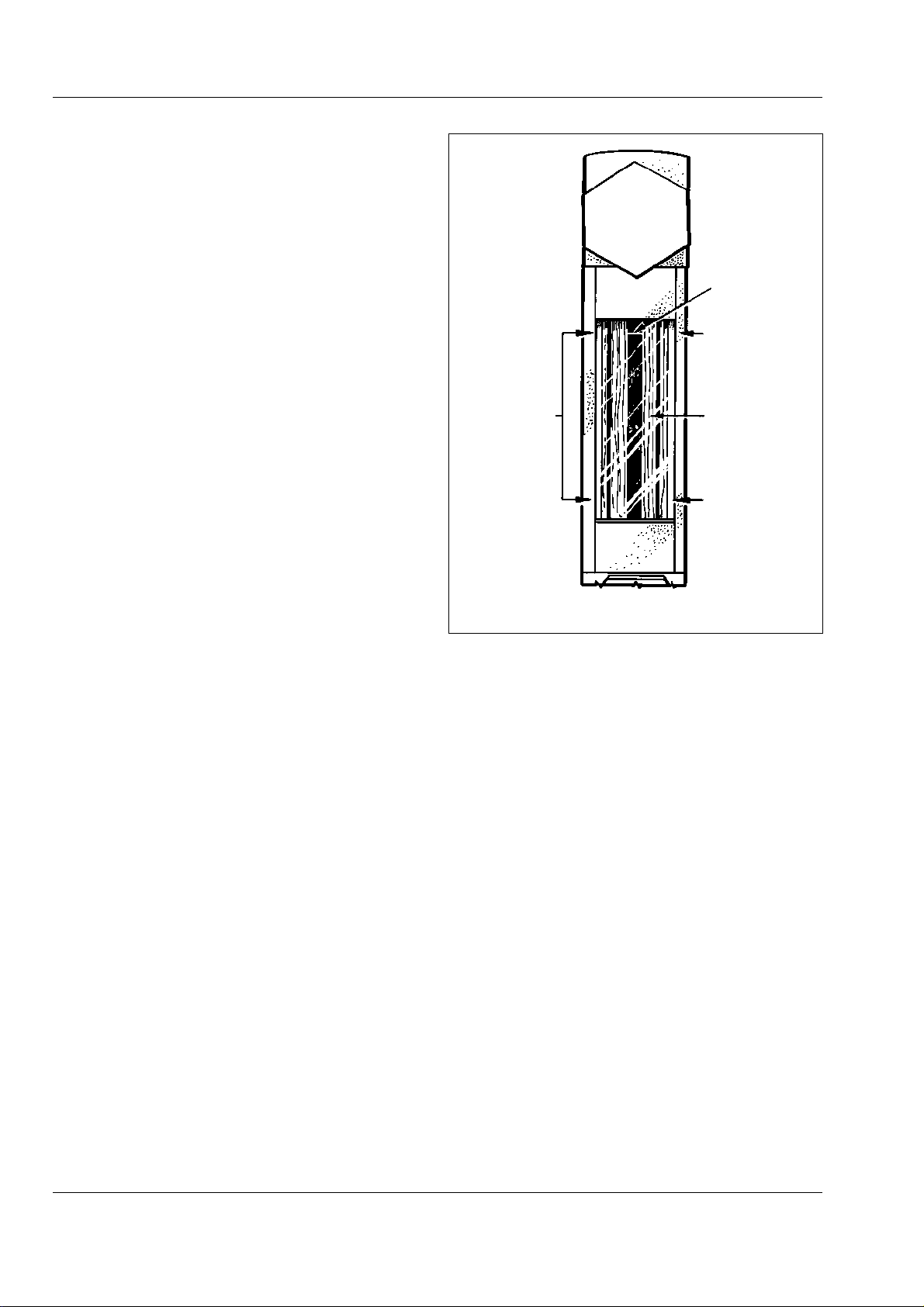
Transmission - Transmission and Mounting
Section 120-0010
level is too low, the converter and clutches will not
receive an adequate supply of oil. If the oil level is too
high, the oil will aerate and the transmission will
overheat. It is absolutely necessary that the oil put into
the transmission be clean.
Oil must be handled in clean containers to prevent
foreign material from entering the system.
Note: Containers or fillers that have been used for
antifreeze or engine coolant solution must not be used
for transmission oil.
Visual Level Indicator
A visual level indicator is mounted on the lower left
side of the transmission main housing and provides a
method of checking the oil level. Refer to Fig. 2.
Cold Oil Level Check
Before starting the engine, check the visual level
indicator or remove the ADD (lower) plug. If oil is
present in the indicator or if oil flows from the plug
opening, the transmission has sufficient oil to permit
safe starting of the engine. If no oil is present, add
sufficient oil to bring the level within the indicator or to
cause a flow from the plug opening. Replace the plug.
Hot Oil Level Check
Note: Observe the condition of the oil in the visual
level indicator or the type of flow from the plug
opening. Foaming or spurting may indicate a false
level.
A hot oil level check is made to determine if there is
sufficient oil for working operation of the transmission.
Select neutral on the transmission range selector and
start the engine. Operate the vehicle until the
transmission reaches a normal operating temperature
of 82 - 103° C (180 - 220° F). Idle the engine, apply
the parking brake and block all road wheels.
Check the visual level indicator or remove the FULL
(upper) oil level check plug. The oil should be within
the indicator limits shown in Fig. 2 or at or near the
level of the plug opening. Add or drain oil as necessary
to bring the oil level within these limits.
Note: The transmission may be operated safely as
long as the oil level is above the ADD (lower) plug.
Oil and Filter Change
After the first 150 hours of operating a new or rebuilt
transmission, the transmission oil and filters should be
changed.
SM - 1250
RED LINE
NO RED
LINE VISIBLE
(OVERFILL)
SAFE
OPERATIONAL
LEVEL AREA
Fig. 2 - Visual Level Indicator
FULL MARK
(CENTRE)
NO OIL VISIBLE
(UNDERFILL)
The transmission oil and filters should be changed at
the intervals specified in Section 300-0020,
LUBRICATION SYSTEM, or sooner, depending on
operating conditions. Also, the oil must be changed
whenever there are traces of dirt or evidence of high
temperature indicated by discoloration or strong odour.
The screen and magnet assembly in the sump should
be removed and cleaned with mineral spirits at each
oil change. Metal particles in the oil (except for the
minute particles normally trapped in the oil filters)
indicate damage has occurred in the transmission
When these particles are found in the filters, the cause
must be established and rectified immediately to
prevent damage to the transmission.
At each oil change, examine the used oil for evidence
of dirt or water. A normal amount of condensation will
emulsify in the oil during operation of the transmission.
However, if there is evidence of water or engine
coolant in the oil, the cause must be established and
rectified immediately to prevent damage to the
transmission.
6
SM 1905 1-00
Page 65
Transmission - Transmission and Mounting
Welding on Vehicles Equipped With CEC
WARNINGS
The ECU can be damaged by improper welding
procedures.
Any time the battery equalizer is
disconnected from the batteries, remove
ground cable first, and reconnect last, to
prevent damaging the component.
When frame or other welding is required, the following
precautions are to be taken to protect the electronic
components.
a. Disconnect battery equalizer ground connection
from the batteries. Disconnect battery cables from
terminal posts (ground cable first). Disconnect battery
equalizer positive connection. Disconnect electrical
connections at the ECU.
b. If additional system ground wires are connected to
the frame, they must be disconnected also.
c. Cover electronic components and wiring to protect
from damage.
d. Do not connect welding cables to electronic
components. Do not weld on electronic components. If
welding is to be done close to electronic components,
the components should be removed prior to the
welding process.
e. On completion of all welding reconnect electrical
connections in the reverse order to step a.
TROUBLESHOOTING
Converter Stall Test
A stall test should be conducted when the power
package (engine and transmission) is not performing
satisfactorily. The purpose of the test is to determine
the engine power output and establish if the
transmission is the malfunctioning component.
Section 120-0010
WARNING
When conducting a stall test, the vehicle must
be positively prevented from moving. The
parking brake must be applied and the vehicle
should be blocked to prevent movement
forward or reverse. Keep people safely away
from the vehicle path. Do not maintain the
stalled condition longer than 30 seconds due
to rapid heating of the transmission oil. With
the transmission in neutral, run the engine at 1
200 - 1 500 rev/min for two minutes to cool the
oil between tests. Do not allow the converterout temperature to exceed 135° C (275° F).
Keep a close check to prevent overheating of
the engine cooling system.
1. Position the vehicle on a level area with room for
movement all round.
2. Apply the parking brake and block all road wheels.
Turn the manual mode key switch to the 'On' position
and the mode selection switch to the 'Power' mode.
3. Apply the service brake, release the parking brake
and select fifth gear on the transmission shift selector.
The transmission will shift to fifth gear and deactivate
the lockup clutch. Apply the parking brake and release
the foot pedal.
4. Accelerate the engine to full throttle and, using a
tachometer of known accuracy, note the maximum
rev/min the engine will attain. Converter-out pressure
should be 2 bar (30 lbf/in²).
Note: The stall speed of each vehicle is noted on the
final inspection records prior to the vehicle leaving the
factory. This can be used as a guide when checking
the stall speed. It is recommended to keep a record of
the stall speed after each major service and use the
previous recorded value as a guide.
5. When the stall check is complete, return the
accelerator to the idle position and move the shift
selector to the neutral position.
Note: Engine power will decrease with an increase in
elevation (altitude), becoming more pronounced at
greater elevation. This will result in a lower engine
speed under converter stall conditions.
SM 1905 1-00
7
Page 66
Transmission - Transmission and Mounting
Section 120-0010
6. During the stall check the transmission oil
temperature should rise while the engine is under load
and drop when the transmission is returned to neutral.
Should the temperature fail to drop it indicates that
there is a problem with the converter.
7. After making allowances for elevation, a low engine
speed may indicate the engine is not delivering full
power. Refer to engine service manual for engine
repair information.
Electronic Troubleshooting
Refer to Section 120-0070, CEC SHIFT SYSTEM for
general electrical troubleshooting. For more detailed
electrical troubleshooting refer to the Allison
Transmission Commercial Electronic Control (CEC)
Troubleshooting Manual SA2712A.
Mechanical Troubleshooting
It is recommended to follow the procedures laid down
MECHANICAL TROUBLESHOOTING CHART
for mechanical troubleshooting, as outlined in the
'Mechanical Trouble Shooting' charts, before carrying
out electrical troubleshooting procedures.
WARNING
Be sure to apply the parking brake, switch off
the engine and block all road wheels before
troubleshooting the vehicle. Should it be
necessary to run the engine, it is imperative
that an operator be present in the cab at all
times, even at idle.
SPECIAL TOOLS
There are no special tools required for the procedures
outlined in this section. Refer to Section 300-0070,
SERVICE TOOLS for part numbers of service tools
which should be used in conjunction with procedures
outlined in the transmission manufacturers service
manual, and general service tools required. These
tools are available from your dealer.
CONDITION REASON REMEDY
A - Transmission overheats High or low oil level Restore proper oil level
Aerated (foaming) oil Refer to condition 'B'
Vehicle overloaded Reduce load
Engine coolant overheated Correct engine overheating
Transmission oil cooler or Clean or replace oil cooler or lines
lines kinked or clogged
Low coolant level Add coolant, check for leaks
Oil leaking Check transmission and lines for leaks
Low main pressure Refer to condition 'V'
Low converter-out pressure Refer to condition 'U'
Vehicle brakes dragging Check parking and service brakes
Torque converter stator locked Check for low top speed of vehicle. Check
torque converter components.
Clutch slipping Overhaul transmission. Replace worn piston
seal rings or clutch plates.
B - Oil is aerated (foaming) Incorrect type of oil used Change oil. Use only oil specified in Section
300-0020, LUBRICATION SYSTEM.
High or low oil level Restore proper oil level
Air entering suction side of Check oil pump bolts and gasket
oil pump
Water in oil Check for source, clean system
8
SM 1905 1-00
Page 67
Transmission - Transmission and Mounting
Section 120-0010
MECHANICAL TROUBLESHOOTING CHART
CONDITION REASON REMEDY
C - Heavy metal debris found Transmission internal failure Completely disassemble, clean and repair
in oil transmission. Replace filters and clean lines
and oil cooler.
D - Coolant found in oil Transmission oil cooler leaking Completely disassemble and thoroughly clean
transmission. Replace all friction faced clutch
plates. Repair or replace oil cooler. Replace
filters and clean external lines.
E - Transmission will not Loss of electrical power Refer to Electronic Troubleshooting
operate in any range
regardless of selector position
F - Transmission continues in Loss of electrical power Refer to Electronic Troubleshooting
the same forward gear
regardless of selector position
Internal mechanical failure Overhaul transmission
Driveline failure Check transmission input and output
Low oil level Restore proper oil level
Low main pressure Refer to condition 'V'
G - Shifting is erratic Refer to Electronic Troubleshooting
H - Transmission operates only Refer to Electronic Troubleshooting
in first, neutral and reverse
I - Transmission shifts to Refer to Electronic Troubleshooting
neutral during reverse
operation, but will operate
normally in all other ranges
J - Vehicle operates in reverse Reverse clutch has failed Overhaul transmission
and moves backwards in (won't release)
neutral when engine is
accelerated, but stalls in all
other gears when engine is
accelerated - Electronic
Troubleshooting OK
K - Vehicle operates in first First and second gear clutch Overhaul transmission
and second gears and moves failed (won't release)
forward in neutral when engine
is accelerated, but stalls in all
other gears when engine is
accelerated - Electronic
Troubleshooting OK
L - Vehicle operates in third Third and fourth gear clutch Overhaul transmission
and fourth gears and moves failed (won't release)
forward in neutral when engine
is accelerated, but stalls in all
other gears when engine is
accelerated - Electronic
Troubleshooting OK
SM 1905 1-00
9
Page 68
Transmission - Transmission and Mounting
Section 120-0010
MECHANICAL TROUBLESHOOTING CHART
CONDITION REASON REMEDY
M - Vehicle operates in fifth Fifth and sixth gear clutch Overhaul transmission
and sixth gears and moves failed (won't release)
forward in neutral when engine
is accelerated, but stalls in all
other gears when engine is
accelerated - Electronic
Troubleshooting OK
N - No power is transmitted in Range clutch failed (won't Overhaul transmission. Check for worn piston
any one range - Electronic apply, slipping) seals, broken piston housing, or worn clutch
Troubleshooting OK plates in that range.
O - Vehicle will operate in Splitter-overdrive clutch won't Overhaul transmission. Check splitter clutches
second, fourth, sixth and release or splitter-direct clutch for worn components.
reverse gears but will not won't apply, slipping
operate in all other gears Electronic Troubleshooting OK
P - Vehicle will operate in first, Splitter-direct clutch won't Overhaul transmission. Check splitter clutches
third and fifth gears but will not release or splitter-overdrive for worn components.
operate in all other gears - clutch won't apply, slipping
Electronic Troubleshooting OK
Q - Slow clutch engagement Low oil level Add oil to proper level
Foaming oil Refer to condition 'B'
Worn piston seals Overhaul transmission
Low main pressure Refer to condition 'V'
R - Vehicle lacks power and Engine malfunction Check engine. Refer to engine service manual.
acceleration
S - High engine speed at Low oil level Add oil to proper level
converter stall
Aerated oil Refer to condition 'B'
Low engine speed at converter Refer to condition 'T'
stall
High engine speed at Refer to condition 'S'
converter stall
Hydraulic retarder partially Check retarder linkage
applied
Vehicle brakes dragging Check parking and service brakes
Stator freewheel clutch failed Overhaul transmission
Low converter-out pressure Refer to condition 'U'
High oil temperature (above Refer to condition 'A'
135° C; 275° F)
10
Clutch slipping, main pressure Overhaul transmission. Replace clutch piston
normal seal rings or clutch plates.
Foaming oil Refer to condition 'B'
SM 1905 1-00
Page 69
Transmission - Transmission and Mounting
MECHANICAL TROUBLESHOOTING CHART
CONDITION REASON REMEDY
T - Low engine speed at Low engine output torque Tune engine and check output
converter stall
U - Low converter-out Low oil level Add oil to proper level
pressure
V - Low main pressure Low oil level Add oil to proper level
Converter element Check for noise at stall; overhaul converter if
interference necessary
Transmission oil not up to Warm up transmission to 82 - 103° C
operating temperature (180 - 220° F)
Oil line leakage (oil cooler or Check for leaks, correct as required
filter)
Plugged oil strainer Clean oil strainer
Defective oil pump Rebuild/replace oil pump assembly
High oil temperature Refer to condition 'A'
Foaming oil Refer to condition 'B'
Section 120-0010
Leaks in hydraulic system Check all external points for leaks; check each
range for localizing internal leaks
Failure in pressure regulator Overhaul valve assembly
Worn input oil pump assembly Rebuild/replace pump assembly
Clogged oil strainer Clean oil strainer
Air leaks at suction side of Check input pump, correct as required
input pump
W - Downshift of transmission Refer to Electronic Troubleshooting
is permitted during lockup
operation
X - Shift quadrant not Failed light bulb Replace the light bulb
illuminated
Y - Reverse signal not Refer to Electronic Troubleshooting
energized
SPECIAL TORQUE SPECIFICATIONS
TORQUE
FIG. NO. ITEM NO. ITEM NAME Nm lbf ft
1 3 Bolt 156 115
1 6 Bolt 278 205
1 10 Bolt 156 115
1 32 Bolt 130 - 156 96 - 115
1 38 Nut 950 - 1 355 700 - 1 000
SM 1905 1-00
* * * *
11
Page 70

THIS PAGE IS INTENTIONALLY LEFT BLANK
Page 71
TRANSMISSION - CEC Plus II Shift System
Section 120-0070
DESCRIPTION
The CEC (Commercial Electronic Control) shift system
continually monitors the transmission and shift system
electrical components and warns the operator when a
problem develops. It also takes action to prevent
damage to the transmission, and provides the
serviceman with diagnostic capabilities so that
problems can be corrected quickly and easily.
The CEC Plus II shift system used on this vehicle
consists of a gear shift selector, an electronic control
unit (ECU), throttle position sensor, transmission output
shaft speed sensor (magnetic pick-up), oil temperature
sensor, solenoids, switches, relays, circuit breakers,
fuses, indicator lights and wiring harnesses.
In addition, CEC provides the following systems
designed to protect the operator and mechanical
components:
Reverse Inhibit - Prevents gear selection if engine is
operating at more than 20% throttle.
Hoist Interlock Pressure Switch - The ECU will shift
the transmission from reverse to neutral if the body
control joystick is moved to the 'Raise' position. When
this circuit has been activated, moving the transmission
shift lever to neutral, then re-selecting reverse, will
engage reverse gear whilst the body is held in the
'Raise' position. This feature is only operational in the
normal automatic driving mode, either Power or
Economy. It is not activated during the manual mode.
WARNING
The standard procedure for raising the body
must still be adhered to.
Body Up Interlock - When the body is raised, the CEC
system will only allow the transmission to operate in
first gear. This feature is only operational in the normal
automatic driving mode, either Power or Economy. It is
not activated during the manual mode.
Parking Brake Interlock - If the parking brake is
applied while the transmission is in neutral, the CEC
system will prevent a shift out of neutral to protect the
brake components. If the parking brake is applied while
the transmission is in gear, the parking brake interlock
will not function and normal shifts will occur.
seconds and then, if the condition fails to correct itself,
locks in gear and prevents any further shifting. The
Check Trans and Do Not Shift lights will both come on.
If this occurs, the ECU must be reset before normal
operation may be resumed.
To reset the ECU if the transmission has locked in
gear because of wheel spinning or a panic stop, stop
the vehicle, select neutral 'N', apply the parking brake,
and turn the ignition key switch to position '0' to shut
down the engine. Wait ten seconds, then turn the
ignition key switch to restart engine. Select reverse 'R',
then neutral 'N'. The Check Trans and Do Not Shift
lights should go off.
Cold Weather Starts - During cold weather, if the
transmission temperature is below -24° C (-10° F) the
Do Not Shift and Check Trans lights will illuminate and
the ECU will prevent the transmission from being
shifted out of Neutral. Between -24° C (-10° F) and
-7° C (19° F) the lights will go out and the ECU will
only permit operation in first or reverse gears. Above
-7° C (19° F), normal operation will be permitted.
CEC PLUS II COMPONENTS
Description and Operation
Refer to Fig. 1.
1. Electronic Control Unit (ECU) - Contains an
electronic microcomputer. The ECU receives
information in the form of electronic signals from
switches and sensors, processes the information
according to shift schedule programs stored on a
programmable read only memory (PROM) chip, and
sends electronic signals to the appropriate solenoids
which control the transmission.
The ECU is programmed to take corrective action to
prevent damage to the transmission if a failure occurs
in the CEC system and has diagnostic capabilities
which allow the serviceman to quickly find and repair
or replace a failed component.
2. Battery Equalizer - Since the ECU continually
draws 12 volts from one of the vehicles batteries, the
battery equalizer is provided to continually monitor and
balance the charge on the batteries.
Lock-in-gear - The lock-in-gear feature is designed to
protect the transmission from damage should wheel
spinning or lockup occur due to poor traction or panic
braking. The ECU will delay making a shift for several
SM 1575 Rev 2 11-00
WARNING
Any time the battery equalizer is disconnected
from batteries, remove ground wire first and
reconnect last to avoid damaging component.
1
Page 72
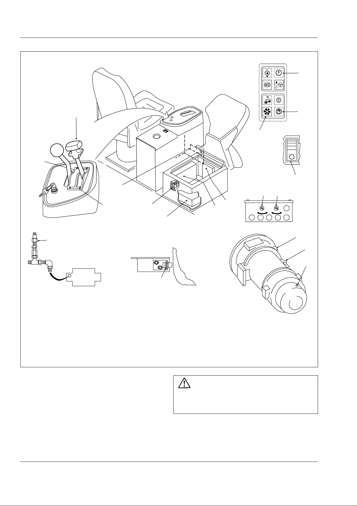
T ransmission - CEC Plus II Shift System
Section 120-0070
SM - 1966
8
10
17
4
7
11
TEST
DO NOT
SHIFT
D
5
4
3
2
1
N
R1
R2
DO NOT
SHIFT
12
6
5
9
2
10
13
1
MANUAL AUTO POWER ECONOMY
3
14
15
BODY
16
18
HYD CONTROL VALVE
1 - Electronic Control Unit (ECU)
2 - Battery Equalizer
3 - CEC Interface Box
4 - Gear Shift Selector
5 - Mode Selection Switch
6 - Manual Mode Switch
7 - Manual Mode Warning Light
8 - Check Trans Warning Light
9 - Check Trans Switch
10 - Do Not Shift Warning Light
11 - In-converter Indicator Light
12 - Digital Data Line
Fig. 1 - CEC Plus II Components
3. CEC Interface Box - Provides the electrical link
between the vehicle harnesses and the CEC
harnesses. The interface box contains fuses and
relays.
4. Gear Shift Selectors - When any one of the
forward drive ranges is chosen, detents will hold the
lever in the selected position. A two-finger latch
release must be pulled up to permit movement of the
lever into and out of neutral 'N' and reverse 'R'.
13 - Circuit Breakers
14 - Lockup Valve & Temp Control
15 - Main Control Valve
16 - Speed Sensor
17 - Reverse Hoist Press Switch
18 - Body Up Proximity Switch
WARNING
Do not allow the vehicle to coast in Neutral.
This practice can result in severe transmission
damage.
The transmission provides six forward ranges, two
reverse ranges and a neutral position. The
transmission upshifts and downshifts automatically
between first range and the highest range selected on
2
SM 1575 Rev 2 11-00
Page 73
Transmission - CEC Plus II Shift System
the range selector in direct response to throttle
position and transmission output speed.
When Reverse is selected the reverse alarm sounds and
the reverse light illuminates at the rear of the vehicle. This
feature warns personnel to the immediate rear of the
vehicle that the operator has shifted to reverse.
When drive 'D' is selected, the transmission
automatically upshifts and downshifts through all six
forward ranges as required by loads and travel
speeds. Selecting a lower range (4th, 3rd etc.) limits
the highest range to which the transmission will
automatically upshift.
If a lower range is selected while moving forward, the
transmission automatically downshifts sequentially to
the selected lower range at maximum controlled
engine speeds. Downshifts will not occur until vehicle
is slowed by use of the service brakes and/or retarder.
When shifting from neutral to start from a standstill, or
to reverse direction, decelerate the engine to idle
speed. To move forward, select drive 'D' and
accelerate the engine to the vehicle load and speed
requirements. The transmission will automatically
upshift from 1st through 6th ranges as travel speed
increases.
With the throttle fully depressed, and the mode
selection switch in the Power position, the
transmission upshifts to the next higher range when
the engine attains maximum rated speed, since
maximum power train output is needed under this
condition. At lower throttle settings where minimum
power train performance is required, the transmission
will upshift to the next higher range at less than
maximum rated engine speed.
Upgrades or soft spots might slow travel speed, even
at full throttle, requiring transmission downshifts to
maintain maximum powertrain performance. When this
occurs, the transmission downshifts automatically.
Shift the transmission to the next lowest range if
transmission 'Hunting' or 'Shift Cycling' occurs.
When temporarily stopped, such as for yielding the
right-of-way to a loaded vehicle, the transmission can
be left in the selected range and the vehicle held
stationary with the service brakes.
However, when stopped for a more extended period
with the engine left running, shift the transmission to
neutral to avoid unnecessary heat buildup and apply
the parking brake.
Section 120-0070
WARNING
Always select Neutral and apply the parking
brake before leaving the operator’s seat.
5. Mode Selection Switch - Gives the option to select
between transmission Power and Economy shift
schedules. The transmission must be in Neutral before
the switch will function.
The transmission torque converter is equipped with a
lockup clutch which, when engaged by the ECU, locks
the converter pump and turbine together as a single
unit and allows power to be transmitted mechanically
from the engine directly to the transmission gearing on
a 1:1 ratio. When the lockup clutch is disengaged, the
torque converter acts as a fluid coupling, multiplying
torque when engine speed is significantly higher than
transmission output shaft speed.
When the mode selection switch is in the Power
position, the ECU controls operation of the lockup
clutch according to signals received by the throttle
position sensor (giving engine speed as a percent of
throttle), the transmission output shaft speed sensor,
and range selector. The ECU may delay application of
the lockup clutch and allow torque multiplication by the
torque converter to take place until a balance is
achieved between engine speed and transmission
output shaft speed before activating the lockup clutch.
Power versus Economy Mode
The Power mode is designed for applications involving
heavy loads and hilly duty cycles where performance
rather than fuel economy is of prime importance.
The Economy mode is designed for applications
involving lighter loads and level duty cycles or where
fuel economy is more important than performance.
In the Economy mode, the ECU controls operation of
the lockup clutch with a timed, preprogrammed
schedule where in second through sixth gears the
lockup clutch is disengaged only long enough to allow
the torque converter’s fluid coupling to absorb shift
shock. Otherwise, the lockup clutch is engaged and no
torque multiplication takes place in second through
sixth gears.
6. Manual Mode Switch - The manual mode facility is
designed as a Service Technician facility to allow stall
checks and clutch pressure checks to be implemented
by Service Personnel, and permit movement of the
vehicle, if necessary, to a repair area. With the manual
mode switch in the 'On' position, the body up interlock
SM 1575 Rev 2 11-00
3
Page 74
T ransmission - CEC Plus II Shift System
Section 120-0070
and hoist interlock pressure switch mechanisms are
disengaged! This allows unauthorised selection of
reverse or any forward gear with the body raised,
constituting a safety hazard. Operators must not use
the manual mode facility when working the vehicle! It
is recommended that the mode selection key is
removed from the unit and retained in a safe place
until required by Service personnel.
Note: The manual mode can only be used if the mode
selection switch is in the Power position and the
transmission is in neutral.
WARNINGS
Do not operate the engine for more than 30
seconds at full throttle with transmission in
gear and output stalled as this will result in
severe overheat damage to the transmission.
The manual mode is not intended to be
used for normal operations. The vehicle should
only be driven at very low speeds in first or
reverse gears if the manual mode is activated,
or damage to the transmission may result.
9. Check Trans Switch - Is used in conjunction with
the check trans warning light to obtain trouble codes
which will indicate shift system malfunctions. Refer to
'Troubleshooting' covered in this section, or, Allison
Commercial Electronic Control (CEC) Troubleshooting
Manual SA2712A, for instructions on finding and
clearing trouble codes and diagnostic procedures.
10. Do Not Shift Warning Light - This warning light is
incorporated in the gear shift selector. The light will
illuminate when the ignition key switch is turned to
position '1' to provide a bulb and system check. It
should go 'Off' a few seconds after the ignition is
switched on.
If the do not shift warning light starts to flash and the
buzzer sounds along with the Check Trans Warning
Light, the ECU has detected a serious problem in the
shift system and will disengage the lockup clutch, if
applied, preventing a shift out of the gear the
transmission is in (Lock-in gear). Any time the do not
shift warning light starts flashing and the buzzer
sounds, bring the vehicle to a stop at the first safe
opportunity and shut down the engine until the
problem is corrected.
7. Manual Mode Warning Light - Illuminates to alert
the operator when the transmission has been switched
to operate in the manual mode. The light should be
'Off' during normal operation.
8. Check Trans Warning Light - Illuminates to alert of
a minor fault in the transmission shift system or
abnormal transmission temperature. The light will
come 'On' when the ignition key switch is turned to
position '1' to provide a bulb and system check and
should go 'Off' a few seconds after the engine is
started and the transmission oil pressure rises.
The check trans warning light will come 'On' during
operation, if the ECU has detected a minor fault in an
electrical component or abnormal transmission oil
temperature. If transmission oil temperature is too
high, stop the vehicle, select neutral 'N', and increase
engine speed to allow a greater flow of oil to the cooler
until oil temperature drops to normal operating range.
In most cases, a minor fault triggering the check trans
warning light will not prevent normal operation from
continuing but, depending on the nature of the
problem, the ECU could take action to protect the
transmission from damage, such as preventing
operating in high gear ranges. If the check trans light
comes 'On', have the problem diagnosed and
corrected at the earliest opportunity.
11. In-convertor Indicator Light - Illuminates when
the transmission is in torque converter drive. It goes
'Off' when Lockup is engaged. In order to avoid
unnecessary waste of fuel, if traffic or other road
conditions permit, the operator should modify throttle
position, or gear held, to achieve a steady road speed
with the torque converter lockup engaged (light 'Off').
12. Digital Data Line - Located in the right hand side
of the transmission control tower. Plug in connector for
diagnostic data reader (DDR).
CEC PLUS II ELECTRICAL CIRCUITS
Note: The following circuits refer to both colour coded
wires (vehicle harnesses) and number coded wires
(Allison harnesses). For ease of explanation, the
number codes are used in the text.
Note: Where wire colours are indicated in the circuits
followed by the Allison number in brackets, this
indicates which Allison wire the vehicle harness wire
will connect to.
Note: Refer to Section 190-0000, CIRCUIT
DIAGRAMS, for vehicle electrical circuits. Refer to
Section 190-0270, SWITCHES AND SENSORS, for
location and description of transmission switches and
sensors.
4
SM 1575 Rev 2 11-00
Page 75
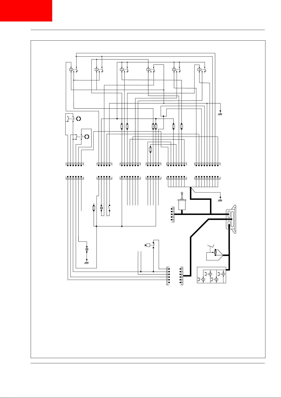
CLICK HERE FOR
HORIZONTAL
DRAWING
Transmission - CEC Plus II Shift System
U/G
U/G
W/U
123 456
U/G
W/U
W/R
RR R
Section 120-0070
SM - 1967
W/B
W
W
B
W R/U
W
BB
S53
U/P
R
U/R
R/U
U/P
BB
U/R
R/P
W/R
R
U/P
B
G
G/W
R/P
G/W
U/W
U
B
RR
U/W
R
R/P
G/R
G
R/P
U
B
B/O
B/O
U
F5F2F1F6F4F7
S52
G/U G/U
R/Y
Y
R
W/P
F3
B/O
B/W
G/R
W/U
U/G
209
W
234
231
202
R/Y
223
J1A
J3
R
W/PWR
222
20387308
R
W/PWW/B
B/O
B/O
306
R/W
205
U/R
222
235
R/PYR/Y
203
215
U/WUG
213
211
G/U
214
B/O
216A
208
W/BRU/P
G/U
330A
308
W/BRU/P
87A
G/U
B
216A
306
B
R/W
330
W/B
RGB
W/B
W/B
R/W
FEDCBA
313
311
309
205
RGB
W/B
W/B
R/W
U/R
R/PYR/Y
322
W/RYR/Y
341
211
230
U/W
75
U/W
U
45
W/Y
201
P1
F7
S4
H27
W/B
W/B W/B
F2
K1
S7
S62
S19
K17
N2N2N2
DDL
CONNECTOR
230
E.C.U.
CEC COMPONENT DESIGNATIONS
F7 - 10 Amp Fuse - CEC (in fuse box)
SM 1575 Rev 2 11-00
Z
RGB
W/B
B
W/B
B
G
R
H27 - Check Trans W/L
K1 - Starter Relay
K17 - Reverse Relay
N2 - Voltage Regulator
TO S22
W/B
S4 - Test Switch
S7 - Park/Emergency Brake Switch
S19 - Dipswitch
S22 - Body Up W/light Switch
S51 - Reverse Hoist Pressure Switch
S52 - Manual Mode Keyswitch
U
B
S53 - Power/Economy Keyswitch
S62 - Retarder On Switch
S51
p
TO S22
B
W
G
W
305
B
309
U
310
G
311
R
313
315
INTERFACE BOX RELAYS
1 - ECU Initial Start
2 - ECU Supply
3 - Retarder (Not Used)
4 - Transmission Check
5 - Reverse Warning
6 - Neutral Start
INTERFACE BOX FUSES
1 - 8 Amp 5 - 5 Amp
TRANSMISSION
2 - 5 Amp 6 - 8 Amp
3 - 8 Amp 7 - 5 Amp
4 - 5 Amp
J1B
WIRE COLOURS
B - Black O - Orange
N - Brown Y - Yellow
U - Blue P - Purple
R - Red W- White
G - Green S - Slate
Fig. 2 - CEC Plus II and Interface Box Circuit Diagram
L - Light Green
5
Page 76
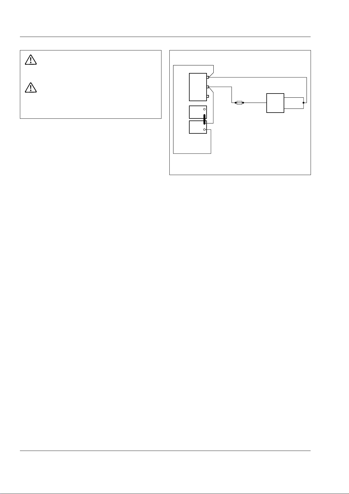
T ransmission - CEC Plus II Shift System
Section 120-0070
WARNINGS
The ECU can be damaged by improper welding
procedures.
Any time the battery equalizer is
disconnected from the batteries, remove
ground cable first, and reconnect last, to
prevent damaging the component.
Note: When frame or other welding is required, the
following procedure must be followed to protect the
electronic components:
Turn ignition keyswitch to position '0' to shut down the
engine and disconnect the batteries.
Disconnect battery equalizer ground connections from
the batteries. Disconnect battery cables from terminal
posts (ground cable first). Disconnect battery equalizer
positive connections. Disconnect electrical
connections at the ECU. On completion of all welding
reconnect electrical connections in the reverse order
to disconnections.
Note: Both 12 and 24 volt circuits are present in the
CEC interface box. Extreme care must be taken, when
making repairs to the system, to avoid damaging the
ECU by introducing 24 volts into a 12 volt circuit.
Ecu Memory Power
The ECU draws 12 volts at a maximum of 10
milliamps (mA) continuously to store trouble codes
and throttle position sensor calibration values. The
ECU stores two trouble codes at a time in its memory.
If the memory power is disconnected trouble codes
and throttle position calibration values will be lost.
Memory power must be reconnected, the engine
started, and the vehicle may have to be put into
operation, to restore trouble codes. Throttle position
calibration values will be recalculated by the ECU
when power is restored and engine started.
SM - 1968
GRD
VANNER
12V
24V
+
W/P(203)
W
381
FUSE 3
B(306)
W/P(203)
ECU
208
209
-
+
-
B(306)
Fig. 3 - ECU Memory Power (12 volts)
Refer to Fig. 3. Current flows from the battery through
lines 381, 203, Fuse 3 and line 203 to the ECU. The
circuit is completed to ground through lines 208 or 209
and line 306.
Circuit Breakers
Refer to Fig. 4. When circuit breakers are switched
'ON' current (24 volts) flows through Fuse 1 and Line
308 to Relays 3, 5 & 6 and Check Trans indicator light.
Current also flows through Fuse 2 and Line 235 to
provide operating power for the shift selector. Circuits
are completed to ground through ECU and Lines 208,
209 and 306.
Ignition Keyswitch
Refer to Fig. 5. When ignition keyswitch is turned to
position '1', current (24 volts) flows through Cable
330A to Relay 1 and back to ground through Line 306,
energising the solenoid. Solenoid in relay 1 closes
switch, allowing current (12 volts) to flow through Line
87, Fuse 6, Switch and Lines 202A and 223A to the
ECU. Circuit is completed to ground through Lines
208, 209 and 306.
6
SM 1575 Rev 2 11-00
Page 77
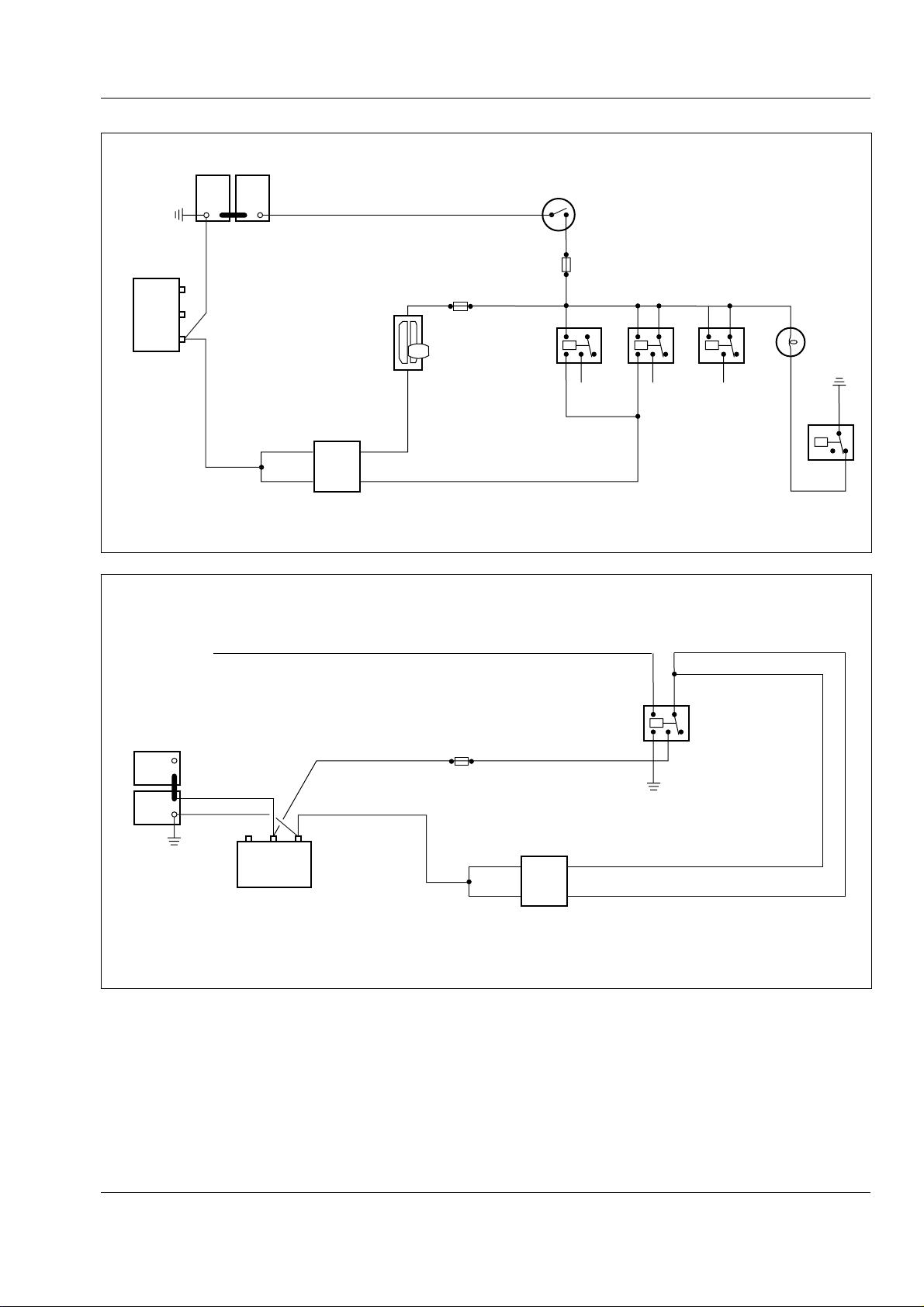
BATTERIES
+
-
-
Transmission - CEC Plus II Shift System
Section 120-0070
SM - 1969
+
R
R
GRD
VANNER
12V
24V
B(306)
B(306)
FROM
IGN. SW.
208
209
ECU
R/G
FUSE 2
(235)
SHIFT
SELECTOR
R
Fig. 4 - Circuit Breakers
W/B(330A)
FUSE 1
R
R
3
R
5
R(308)
R
6
CHECK
TRANS
LIGHT
B(306)
R4
U/P
(87A)
SM - 1970
U/G(223)
W/U(202A)
+
-
+
-
BATTERIES
W(381)
12V
24V
VANNER
W(87)
GRD
FUSE 6
208
209
W
ECU
Fig. 5 - ECU Operating Power - Ignition Switch
RELAY 1
(N.O.)
B(306)
SM 1575 Rev 2 11-00
7
Page 78
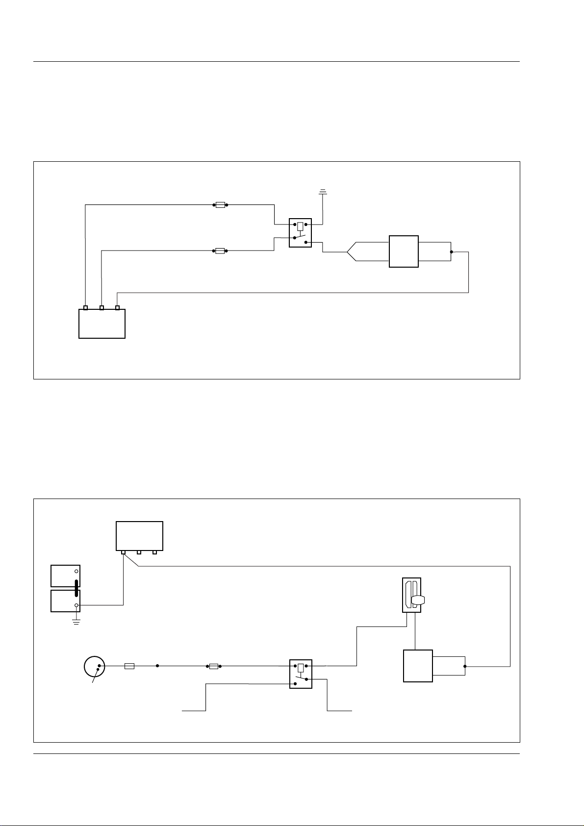
T ransmission - CEC Plus II Shift System
Section 120-0070
ECU Operating Power
Refer to Fig. 6. When the engine is started, current
(24 volts) flows through Line 330 and Fuse 7 to Relay
2, energizing solenoid.
B(306)
FUSE 7
FUSE 6
W
Fig. 6 - ECU Operating Power
W/B(330)
12V
24V
VANNER
W(87)
GRD
Circuit is completed to ground through line 306.
Solenoid in Relay 2 closes Switch allowing current
(12 volts) to flow through Fuse 6, Line 87, Switch and
Lines 202A or 223A to the ECU. Circuit is completed
to ground through Lines 208 or 209 and Line 306.
SM - 1971
RELAY 2
B(306)
202
223
ECU
208
209
Neutral Start Circuit
Refer to Fig. 7. The Neutral Start circuit prevents the
engine from being started unless the shift selector is in
Neutral position. When ignition keyswitch is turned to
position '1', current (24 volts) flows through Line 341
and Fuse 4 to Relay 6, energizing solenoid. Current
continues through Line 231 to shift selector, and goes
VANNER
GRD
12V
24V
+
-
+
-
BATTERIES
B(306)
IGN.
SW.
SOLENOID
TERMINAL
W/R W/R R/P(341)
TO CAB
WIRING
FUSE 4
R(308) U(45)
to ground when selector is in Neutral through Line 210,
ECU, Lines 208 or 209 and Line 306. Solenoid in
Relay 6 closes Switch, allowing current (24 volts) to
flow through Line 308, Switch and Line 45 to start
solenoid. Refer to SECTION 190-0000, CIRCUIT
DIAGRAMS for continuation of starter circuitry.
SM - 1972
B(306)
SHIFT
SELECTOR
G/R
(231)
RELAY 6
TO START
SOLENOID
ECU
210
208
209
Fig. 7 - Neutral Start Circuit
8
SM 1575 Rev 2 11-00
Page 79

Transmission - CEC Plus II Shift System
B(306)
R(308)
B(306)
208
209
G/W
(215)
R/W
R
W/R
(330)
U/P(87A)
GRD
12V
24V
ECU
VANNER
+
+
-
-
FUSE 7
FUSE 1
BATTERIES
BATTERY
DISCONNECT
RELAY
B(306)
B(306)
B(308)
RELAY 4
N.C.
CHECK
TRANS
LIGHT
Section 120-0070
Check Trans Light
The Check Trans light has two functions: to warn the
operator of a system failure and to flash trouble codes
when the test switch is activated.
Normal Operation And Warning
Refer to Fig. 8. When the ignition keyswitch is turned
to position '1', current (24 volts) flows through the
circuit made by Fuse 1, Lines 308 and 87A, turning
'On' the Check Trans light.
When the engine is started, a switch in the ECU
closes, allowing current (24 volts) to flow through the
circuit made by Fuse 7, Lines 330, 215, 208 or 209
and 306. Relay 4 solenoid is energized, opening relay
switch and turning 'Off' the Check Trans light.
Should the ECU detect a system failure, it will open
internal switch, deactivating relay 4 solenoid. Relay
switch closes, turning 'On' the Check Trans light to
warn operator of failure.
SM - 1973
Fig. 8 - Check Trans Light
Obtaining Trouble Codes With Test Switch
Refer to Fig. 9. When the test switch is depressed,
circuit to ground from ECU through line 216A and 306
is completed, signalling ECU to supply diagnostic
codes to Check Trans light. When test switch is
24V
12V
VANNER
GRD
BATTERY
DISCONNECT
RELAY
SM 1575 Rev 2 11-00
R(308)
R
R/W
B(306)
B(306)
-
-
+
+
BATTERIES
FUSE 1
Fig. 9 - Obtaining Trouble Codes With Test Switch (Engine Running)
depressed, ECU closes internal switch, energizing
relay solenoid which opens relay switch, turning Check
Trans light off. ECU opens and closes internal switch
to flash trouble codes with Check Trans light. The
engine must be running.
SM - 1974
208
209
B(308)
FUSE 7
CHECK
TRANS
LIGHT
W/R
(330)
RELAY 4
N.C.
U/P(87A)
B(306)
G/W
(215)
TEST
SW.
ECU
B(306)
G/U(216A)
B(306)
9
Page 80
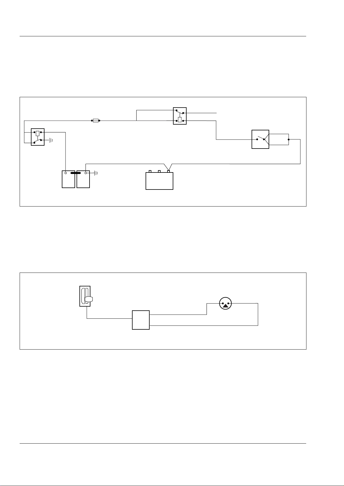
T ransmission - CEC Plus II Shift System
Section 120-0070
Reverse Alarm
Refer to Fig. 10. When the shift selector is placed in
Reverse, ECU closes circuit allowing current (24 volts)
to flow through Line 308 and Fuse 1 to Relay 5,
energizing solenoid. Current flows through Line 214 to
R(308)
R(308)
BATTERY
DISCONNECT
RELAY
R
+
BATTERIES
FUSE 1
B(306)
-
-
+
R(308)
24V
VANNER
Fig. 10 - Reverse Alarm
ECU and back to ground through Lines 208 or 209 and
Line 306. Solenoid closes Switch, allowing current to
flow through Line 308, Switch and Line 75 to reverse
alarm. Refer to SECTION 190-0000, CIRCUIT
DIAGRAMS for continuation of Reverse Alarm circuitry.
SM - 1975
208
209
12V
RELAY 5
GRD
U/W(75)
TO REVERSE RELAY
ECU
G(214)
B(306)
Reverse Hoist Pressure Switch
Refer to Fig. 11. The Reverse Hoist Pressure switch is
a safety feature to prevent the vehicle from backing up
while the body is being raised. Current from the ECU
flows through line 305, microswitch and line 309. If
pressure switch is opened by the body control valve
SHIFT
SELECTOR
ECU
Fig. 11 - Reverse Hoist Pressure Switch
Parking Brake Interlock
Refer to Fig. 12. The Parking Brake Interlock prevents
a shift out of Neutral when the parking brake is
applied. When the parking brake is applied, switch
opens, breaking the circuit to ground. The ECU then
being moved to the 'Raise' position, current is
interrupted and ECU will shift transmission to Neutral.
To obtain Reverse again, switch must be opened and
shift selector must first be placed in Neutral or a
forward range. This interlock will not prohibit shifts to a
forward range while body is being raised.
SM - 1976
B(309)
W(305)
prevents a shift out of Neutral. This interlock will not
inhibit shifting if the parking brake is applied while the
transmission is operating in reverse or any forward
range.
10
SM 1575 Rev 2 11-00
Page 81
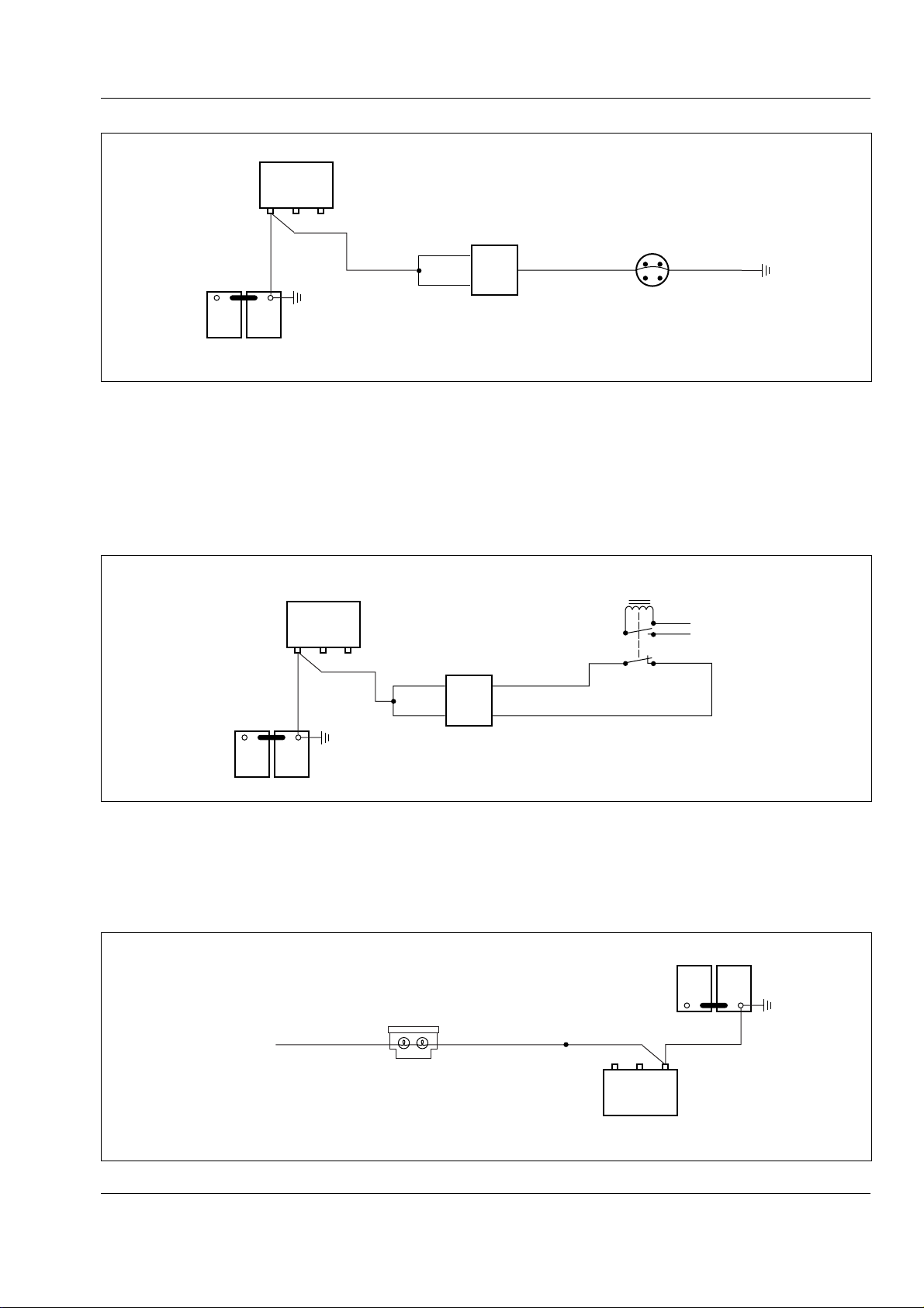
Transmission - CEC Plus II Shift System
Section 120-0070
VANNER
GRD
12V
24V
B(306)
-
+
+
BATTERIES
-
208
209
Fig. 12 - Parking Brake Interlock
Body Up Interlock
Refer to Fig. 13. When the body is raised off the
chassis, the proximity switch opens to complete the
circuit through Lines 309 and 310 to the ECU. The
ECU then prevents the transmission from shifting
above 1st gear until the body is lowered and the
VANNER
GRD
12V
24V
B(306)
B(306)
208
209
ECU
R(222) B(309)
N.C.
N.O.
EMERGENCY
PARK BRAKE SW.
N.C. - RUN POSITION
N.O. - PARK POSITION
proximity switch closes.
Note: CEC wires B (309) and U (310) are 12 volt and
P/G and P/R wires for the body up circuit are
24 V. Improper connection of wires could lead to CEC
damage.
BODY-UP
PROXIMITY SW.
P/R
24V
P/G
B(309)
ECU
U(310)
SM - 1977
SM - 1978
-
-
+
+
BATTERIES
Fig. 13 - Body-up Interlock
Shift Selector Illumination
Refer to Fig. 14. When the panel light switch is closed,
current (24 volts) flows through Line 230 to the shift
selector. Lamps are 12 volts, wired in series, so that if
SHIFT
SELECTOR
TO PANEL
LIGHT SW.
LAMPS
Fig. 14 - Shift Selector Illumination
one bulb burns out, both lamps will cease functioning.
Circuit is completed to ground through lines 234 and
147 to the panel ground.
SM - 1979
12V
24V
VANNER
BATTERIES
+
B(306)B(306)B/W(234)R/Y(230)
GRD
+
-
-
SM 1575 Rev 2 11-00
11
Page 82
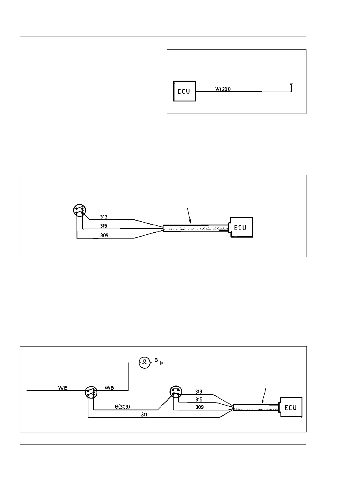
T ransmission - CEC Plus II Shift System
Section 120-0070
ECU Electromagnetic Shield - Ground
Refer to Fig. 15. Must be grounded to protect ECU.
Mode Selection Switch
Refer to Fig. 16.
1. With mode selection switch in Economy (open)
position, ECU will control transmission as per the
Economy mode shift schedule.
MODE
SELECTION
SWITCH
SM - 426
GROUND TO
PASSENGER
SEAT BOX
Fig. 15 - ECU Electromagnetic Shield - Ground
2. With mode selection switch in Power (closed)
position, Lines 313 and 315 are connected to Line 309
and the ECU will then control the transmission as per
the Power mode shift schedule.
SM - 429
SECONDARY MODE
HARNESS - J3
Fig. 16 - Mode Selection Switch
Manual Mode Switch
Refer to Fig. 17.
1. With ignition keyswitch at position '2' and manual
mode switch 'On' (closed) indicator light on console
will illuminate.
2. When mode selection switch is in the Power
(closed) position and manual mode switch is in the
'On' (closed) position, Lines 311, 313 and 315 are all
IND. LIGHT
MANUAL
MODE
SWITCH
24V SUPPLY
FROM IGN. SWITCH
connected to Line 309 and ECU will change operation
of transmission from automatic to manual.
Note: Both switches must be closed and transmission
in neutral to obtain manual mode.
Note: CEC wires B (309) and 311 are 12 volt and
W/B wires at manual mode switch are 24 V. Improper
connection of wires could lead to CEC damage.
SM - 430
MODE
SELECTION
SWITCH
SECONDARY MODE
HARNESS - J3
12
Fig. 17 - Manual Mode Switch
SM 1575 Rev 2 11-00
Page 83
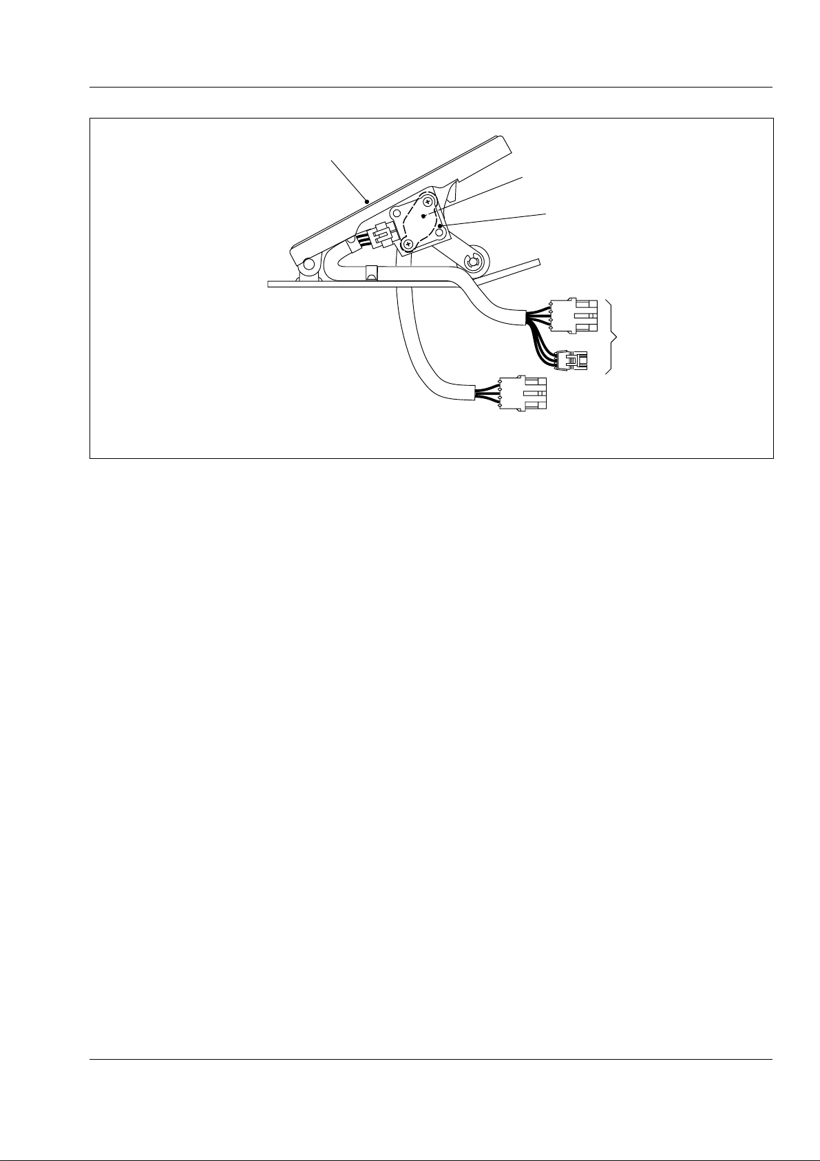
1
1 - Throttle Pedal Assembly
2 - Sensor and Harness - Engine
3 - Sensor and Harness - Transmission
Transmission - CEC Plus II Shift System
Section 120-0070
SM - 1980
3
2
ENGINE
C B A
TRANSMISSION
Fig. 18 - Throttle Sensor
VALVE BODY SOLENOIDS
The hydraulic circuits and valves within the electro-
hydraulic valve bodies are controlled by continuous
power solenoids. The solenoids are located in
separate valve bodies and they shift the valve spools
to direct hydraulic oil to the various clutch packs within
the transmission.
TEMPERATURE SENSOR
Temperature Sensor is mounted in the lockup valve
body cover. The ECU constantly monitors
transmission oil temperature and will not permit shifts
to occur when the oil temperature is -24° C (-10° F) or
below. At this temperature, operation is restricted to
Neutral and both the Do Not Shift and Check Trans
lights will be on. From -22° C (-9° F) to -7° C (+19° F)
operation will be restricted to Neutral, First and
Reverse. Once transmission oil temperature reaches
121° C (250° F) the Check Trans light will come on
and the ECU will restrict operation to Reverse, Neutral
and First through Fourth gears. Temperatures can
easily exceed 121° C (250° F) when the retarder is
being used to help slow the vehicle while descending
grades. When the oil temperature falls below 121° C
(250° F) the Check Trans light will go off. Refer to
Section 190-0270, SWITCHES AND SENSORS.
ELECTRONIC FOOT PEDAL
Refer to Fig. 18. The dual control electronic foot pedal
provides an electronic signal to the engine's fuel
control system in proportion to the degree of pedal
actuation, an electronic signal is also sent to the
transmission ECU.
Note: The electronic controlled engine will override the
electronic foot pedal position until the engine is
warmed up to the correct operating temperature. The
engine MUST be started with the foot 'OFF' the
electronic foot pedal.
The control system continually monitors the engine
and warns the operator when a problem develops. The
system also takes action to prevent damage to the
engine and provides the serviceman with diagnostic
capabilities. Refer to Section 110-0030, ENGINE AND
MOUNTING.
SM 1575 Rev 2 11-00
13
Page 84
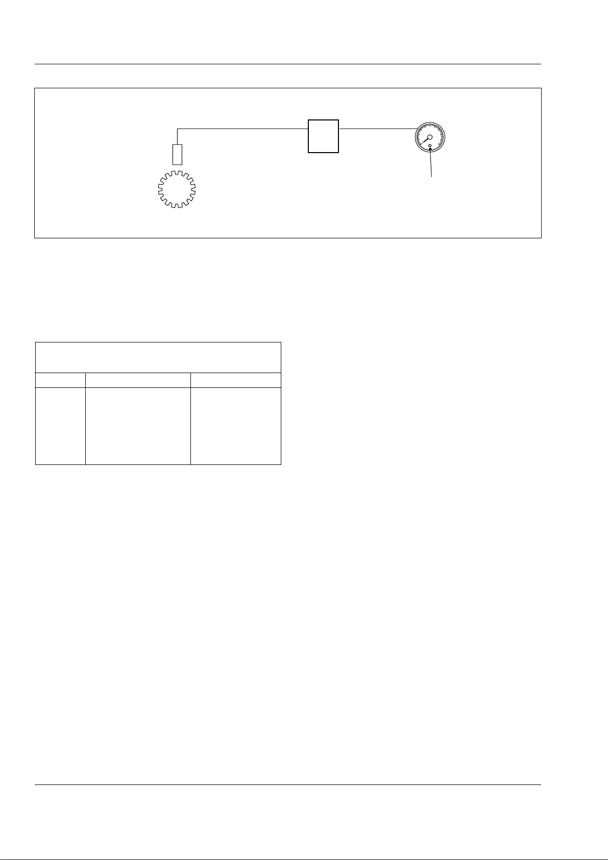
T ransmission - CEC Plus II Shift System
Section 120-0070
SM - 1981
TRANSMISSION
OUTPUT SPEED
SENSOR
Fig. 19 - Electronic Speedometer Output
Speedometer/Odometer
Refer to Fig. 19. Driven by a signal from the CEC, the
speedometer indicates travel speed in kilometers per
hour and miles per hour. A digital odometer is
incorporated in the speedometer to record the
distance travelled by the vehicle at any given time.
Speedometer Calibration Table All units with standard tyres
Unit Transmission Pulses
TR35 CBLT-754 20200
TR40 M5600A 188600
TR45 M5600A 188600
TR60 M6600AR 208580
TR70 M6600AR 208580
TR100 DP-8963 249120
Speedometer Calibration
1. Determine the impulses/mile required. Reference
speedometer calibration table.
WIRE 205
ECU
SPEEDOMETER
20
30
10
40
0
50
CALIBRATION BUTTON
Transmission Output Speed Sensor
This is installed in the transmission rear cover. The
sensor should be screwed in until it makes contact with
the output gear and then backed out 3/4 turn and locked
into place with the jam nut. Tighten the jam nut to
17 - 21 Nm (13 - 16 lbf ft). Refer to Section 190-0270,
SWITCHES AND SENSORS.
Hoist Interlock Pressure Switch
Located in a tee installed in body hoist control valve.
The hoist interlock is a safety feature to prevent the
vehicle from backing up while the body is being raised.
If the pressure switch is opened by the body control
joystick being moved to the 'Raise' position, current is
interrupted and the ECU will shift the transmission to
Neutral. To obtain reverse gear whilst the body is held
in the raise position, move the transmission shift lever
to Neutral, then re-select reverse gear. This interlock
will not prohibit shifts to a forward range while the body
is being raised. Refer to Section 190-0270,
SWITCHES AND SENSORS.
2. Depress and hold calibration button on the
speedometer and turn the ignition keyswitch to
position '1'.
3. Release button when PULSE is displayed. The
second digit will flash. Depress the button until the
desired number is displayed the release the button
for a few seconds until the next digit flashes.
4. Repeat step 3 to obtain the desired impulses/mile.
After a few seconds only two digits will be displayed.
The speedometer is now calibrated.
14
TROUBLESHOOTING
The ECU is a small computer with operating limits
programmed into its memory. Whenever the ECU
detects a condition which falls outside those limits, or a
malfunctioning component, the Check Trans light, or
Do Not Shift lights will be activated and a trouble code
stored in the ECU’s memory. Two soft codes
(indicating problems which may inhibit but not prevent
operation) or two hard codes (indicating problems
which will limit or prevent operation), or one of each,
can be stored in the memory at one time. The trouble
codes identify which circuit the problem is in. The
circuits consist of a component such as a solenoid, the
applicable wiring harness and the ECU.
Both the Check Trans and Do Not Shift lights will come
'On' when the ignition keyswitch is turned to position
'1'. The Check Trans light will stay on until the engine
SM 1575 Rev 2 11-00
Page 85

Transmission - CEC Plus II Shift System
Section 120-0070
is started. The 'Do Not Shift' lights will go 'Off' when
the ignition is switched on, unless the ECU has
detected a failure in the system. Depressing the test
button when the engine is running, will turn 'Off' the
Check Trans light and call up a trouble code, if one is
present. In the case of an intermittent problem, such
as a line which shorts to ground occasionally due to
vehicle movement, the lights may go on and off, but a
trouble code will remain stored in the memory.
In an electronic system such as the CEC system, it is
extremely important that connections at terminal
blocks, grounds to vehicle frames, and all connectors
be clean and secure. Connectors may be cleaned with
a good quality solvent which does not conduct
electricity and evaporates quickly (See Special Tools).
Excess solvent should be shaken out or gently blown
out with compressed air after cleaning.
FINDING TROUBLE CODES
Check Trans Light
Running the engine and depressing the test switch will
cause the ECU to enter the diagnostic mode. The
ECU will cause the Check Trans light to flash a trouble
code, if present.
For example: FLASH - PAUSE - FLASH - FLASH -
FLASH - LONG PAUSE denotes a Code 13.
If more than one trouble code is stored in the memory,
the most important code will be flashed first. The
problem indicated by the first code must be corrected
and the code cleared from the memory before another
code can be found.
Diagnostic Data Reader
Using a diagnostic data reader, both codes can be
found at the same time. Plugging the diagnostic data
reader into the Digital Data Line (DDL) connector
(12, Fig. 1) under the dash panel, on the steering
column mounting bracket, will automatically cause the
ECU to enter the diagnostic mode. Ignition keyswitch
must be turned to position '1'.
turned to position '0', then back to position '1 and shift
into Reverse and back to Neutral. If the codes are still
present, the problem has not been corrected.
Note: After clearing a Code 21 (Throttle Position
Sensor) the ignition keyswitch may have to be turned
'On' and 'Off' as many as five times to reset the self
calibration feature of the throttle position sensor.
The following diagnostic procedures are a summary of
troubleshooting procedures given in the Allison
Commercial Electronic Control (CEC) Troubleshooting
Manual SA 2712A. This manual contains detailed step
by step procedures for diagnosing and correcting
problems indicated by the trouble codes.
It is essential that the serviceman has an accurate
Volt-Ohm Meter (VOM) in order to correctly diagnose
problems in the CEC system.
Fig. 20 is an electrical circuit view showing the terminal
numbers and wire numbers for the CEC J1A, J1B and
J3 harnesses connecting the various components of
the system.
Fig. 21 shows the locations of the terminals in Fig. 20
in their connectors. Check for intermittent shorts or
open circuits by moving harnesses with VOM probes
connected to the applicable terminals. For step-bystep procedures for finding shorts or open circuits in
harnesses or components, refer to Allison Commercial
Electronic Control (CEC) Troubleshooting Manual
SA 2712A.
Note: Both 12 and 24 volt circuits are present in the
control box interface. Extreme care must be taken,
when making any repairs to the system, to avoid
damaging the ECU by introducing 24 volts into a 12
volt circuit.
When troubleshooting leads to replacement of the
ECU, always check for an over voltage condition. If too
high a voltage damaged the ECU and the condition is
not corrected the replacement ECU may also be
damaged.
Voltage limits for the ECU are:
CLEARING TROUBLE CODES
Trouble codes should always be cleared from the ECU
memory after repairs are made. To clear the trouble
codes, make sure the ignition keyswitch is turned to
position '1', depress the test switch, shift into Reverse
and wait a few seconds, then shift back to Neutral. If
the codes do not clear, turn the ignition keyswitch is
SM 1575 Rev 2 11-00
9 volts - minimum
16 volts - continuous
18 volts - 10 minutes
24 volts - 2 minutes
15
Page 86
T ransmission - CEC Plus II Shift System
Section 120-0070
WARNINGS
To prevent any unexpected shift during
removal of wiring harnesses, shut down
engine and switch 'OFF' both circuit breakers.
Be sure to apply the parking brake, shut
off the engine and block all road wheels before
any troubleshooting of the main valve body
solenoids. Accidental activation of a solenoid
while the engine is running could cause the
vehicle to run away.
Code 13 - Low Battery Voltage
System Response:
1. If transmission is in neutral, Check Trans and Do
Not Shift lights will come on. If forward or reverse is
selected, shift will not occur.
2. If transmission is in forward or reverse and a shift is
made, the code will be set in memory and no lights will
come on. Shifts may be erratic or not made.
Probable Cause:
a. Insufficient voltage supplied to ECU.
b. Intermittent open circuit on power to ECU.
c. Intermittent or partial short to ground on power to ECU.
Remedy:
1. Check battery voltage with VOM. Fully charged
batteries should measure 28 ± 1 volt.
2. Check vehicle charging system. With engine
running, voltage regulator should put out 28 volts.
Charge and recheck batteries.
Probable Cause:
a. Throttle sensor failure.
b. Shorts or open circuits in harness wiring.
Remedy:
1. Check cable for binding.
2. Connect VOM probes to sensor terminals A & C
(L, Fig. 21). If reading is not between 9 000 and
15 000 ohms replace sensor.
3. Connect VOM probes to sensor terminals A & B
(L, Fig. 21). Stroke sensor slowly from closed to full
throttle position and back. If VOM reading does not
increase smoothly from at least 500 ohms to
15 000 ohms, replace sensor.
4. Connect one VOM probe to vehicle ground, other to
sensor terminals A, B & C. VOM meter should not
record continuity.
5. Check J1B harness wiring for shorts or open circuits.
6. If fault cannot be located, replace ECU.
Code 22 - Transmission Output Shaft
Speed Sensor
System Response:
The Check Trans and Do Not Shift lights will come on.
All shifts will be prevented and lockup clutch
disengaged. If this happens due to wheel lockup
(panic braking) or wheel spinning, the engine must be
shut down, ignition keyswitch turned to position '0' and
then back to position '1', engine restarted, and Neutral,
Reverse and Neutral selected to reset ECU.
3. Refer to Fig. 2. Check circuits supplying power to
ECU through interface.
4. Input voltage to ECU can be checked with a digital
analyser. Input voltage should be 10.5 - 16 volts. Place
load on batteries by turning on all vehicle accessories
and recheck input voltage. If input voltage is within
limits and Code 13 recurs, replace ECU. If input
voltage is not within limits check all connections
between battery and ECU.
Code 21 - Throttle Position Sensor
System Response:
When sensor is stroked into error zone, the Check
Trans light will come on. ECU will assume 100%
throttle. Shift will occur at either closed throttle or full
throttle points.
16
Probable Cause:
a. Sensor failure.
b. Open circuit or short in harness wiring.
c. Dirty or loose connections.
d. Sensor not adjusted properly in rear cover.
e. Unusually rapid deceleration, or wheel spinning.
Remedy:
1. Check speed sensor to ensure that it is properly
threaded into rear cover, adjusted, and locked into
place with jam nut.
2. Connect VOM probes to sensor terminals A & B (M,
Fig. 21). If VOM reading is less than 50 ohms or
greater than 200 ohms, replace sensor.
3. Connect one VOM probe to transmission housing,
other to terminal A, then B. VOM meter should not
record continuity.
SM 1575 Rev 2 11-00
Page 87
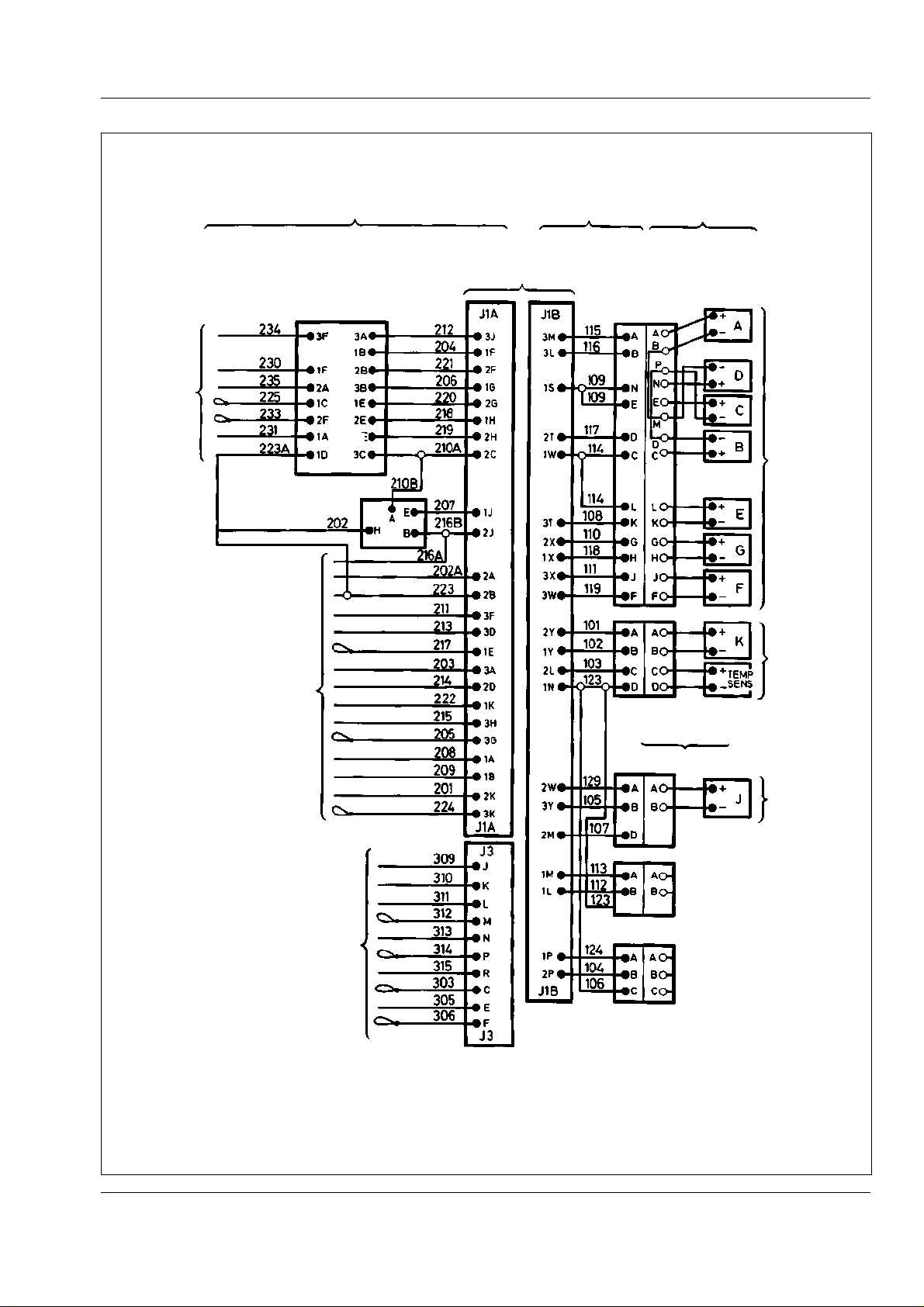
Transmission - CEC Plus II Shift System
Section 120-0070
SM - 432
TO
CONTROL
BOX
INTERFACE
CONNECTOR TO
SHIFT SELECTOR
DIGITAL DATA
LINE CONNECTOR
TO CONTROL
BOX INTERFACE
J1A HARNESS
TO P/BRAKE SW
J1B HARNESS
CONNECTORS
TO ECU
MAIN VALVE
BODY HARNESS
CONNECTORS AT
MAIN VALVE
BODY COVER
MAIN
CONTROL
VALVE
SOLENOID
CONNECTORS
LOCKUP VALVE
SOLENOID
AND TEMP
SENSOR
CONNECTORS
AT LOCKUP
VALVE BODY COVER
LOCKUP VALVE BODY HARNESS
SM 1575 Rev 2 11-00
TO CHASSIS GRD
TO SECONDARY
MODE SWITCHES
Fig. 20 - Electrical Circuit - J1A, J1B and J3 Harnesses
TRIM BOOST
SOLENOID
CONNECTORS AT
TRANSMISSION
OUTPUT SHAFT
SPEED SENSOR
CONNECTORS AT
THROTTLE
POSITION SENSOR
CONNECTORS AT
TRIM BOOST
VALVE
SELECTION MODE
HARNESS CONNECTOR
TO ECU
17
Page 88
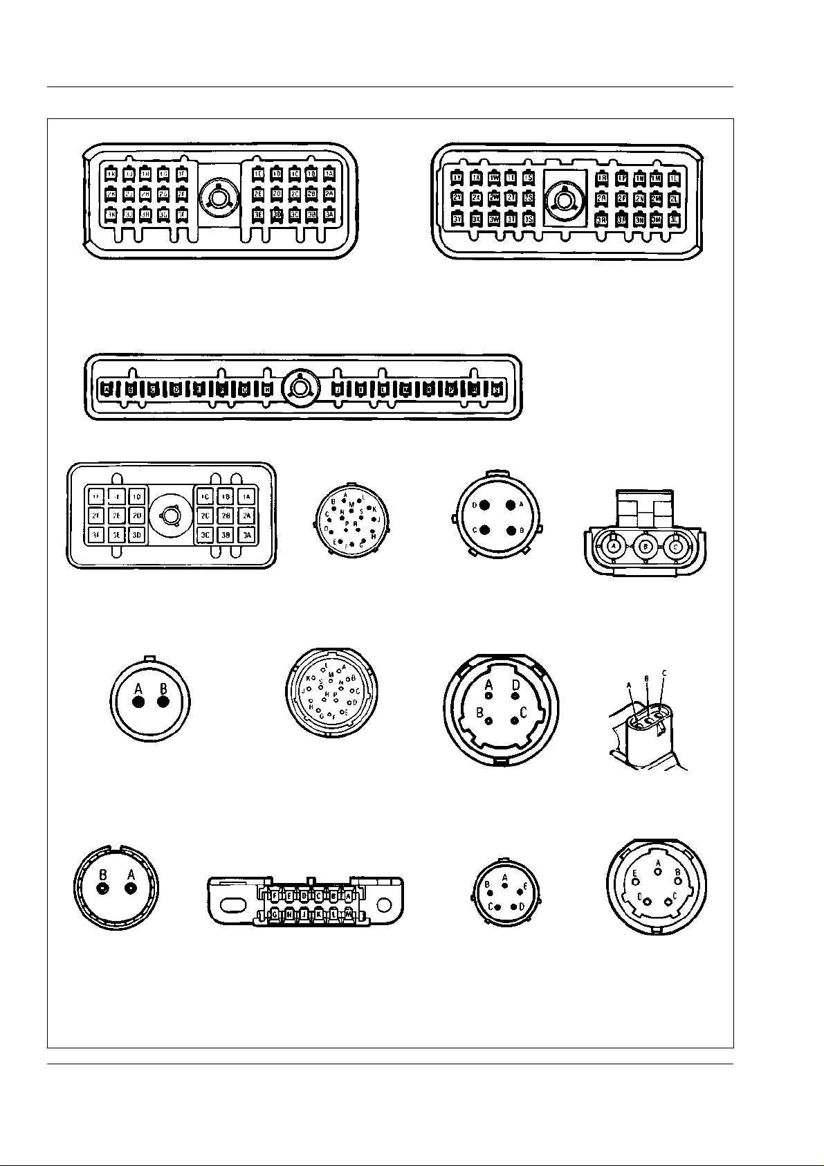
T ransmission - CEC Plus II Shift System
Section 120-0070
SM - 433
B - J1B HARNESS CONNECTOR TO ECUA - J1A HARNESS CONNECTOR TO ECU
C - J3 HARNESS CONNECTOR TO ECU
D - J1A HARNESS CONNECTOR TO
SHIFT SELECTOR
H - J1B HARNESS CONNECTOR
TO TRANS OUTPUT SHAFT
SPEED SENSOR
E - J1B HARNESS
CONNECTOR TO
MAIN VALVE BODY
J - MAIN VALVE BODY
HARNESS CONNECTOR
F - J1B HARNESS
CONNECTOR TO
LOCKUP VALVE BODY
K - LOCKUP VALVE
BODY CONNECTOR
D - J1A HARNESS
CONNECTOR TO
SHIFT SELECTOR
G - J1B HARNESS
CONNECTOR TO
THROTTLE POSITION
SENSOR
L - THROTTLE POSITION
SENSOR CONNECTOR
M - SPEED SENSOR
CONNECTOR
18
N - DIGITAL DATA LINE
CONNECTOR - J1A HARNESS
Fig. 21 - Harness Connectors
1/2 SHIFT/TRIM BOOST
VALVE BODY CONNECTOR
J1B HARNESS
CONNECTOR TO
1/2 SHIFT/TRIM
BOOST VALVE
SM 1575 Rev 2 11-00
Page 89
Transmission - CEC Plus II Shift System
Section 120-0070
4. Check J1B harness wiring for shorts or open circuits.
5. If fault cannot be located, replace ECU.
Code 23 - Shift Selector
System Response:
The Check Trans light will come on. Last good
command from the shift selector will be used. Shifting
may still occur up to and including the range selected.
Probable Cause:
a. Shift selector failure
b. Shorts or open circuits in harness wiring.
Remedy:
1. Check J1A harness connectors at the shift selector
and ECU.
2. Check for shorts or open circuits in J1A harness
wiring. Refer to Fig. 20 for applicable terminals and
wire numbers.
3. If fault cannot be found using steps 1 & 2, install a
new shift selector and reconnect all harness
connectors. Test drive the vehicle and check for
presence of trouble code. If trouble code recurs,
replace new shift selector with old, check connectors
and wiring again. If trouble code is still present,
replace ECU.
2. Check engine coolant temperature.
3. Check oil cooler and lines for blockage.
4. Stop vehicle, run engine at high idle until
temperature drops.
Code 33 - Temperature Sensor
System Response:
If oil temperature is above 204° C (350° F) or below
-73° C (-100° F), the Check Trans light will come on
and code set in memory.
Probable Cause:
a. Sensor failure.
b. Oil temperature too hot or too cold.
c. Short or open circuit in harness wiring.
Note: A CODE 33 may erase a previously diagnosed
CODE 24.
Remedy:
1. Check transmission oil level.
2. Check cooling system.
3. Connect VOM probes to pins C & D on lockup valve
body connector (K, Fig. 21). VOM reading should be
5 000 to 130 000 ohms.
Code 24 - Oil Temperature
System Response:
1. Below -23° C (-10° F), Check Trans and Do Not
Shift lights will come on. Transmission will not shift out
of Neutral. Code will NOT be set in memory. Warming
oil to above -23° C (-10° F) will turn off lights.
2. Between -23° C (-10° F) and -7° C (20° F),
operation is limited to Reverse, Neutral and First
gears. No lights will come on. No code is set in
memory. Warming oil above -7° C (20° F) will allow
normal shifting.
3. Above 121° C (250° F), Check Trans light will come
on and shifts to Fifth or Sixth gear will not be
permitted. Code will be set in memory. Light will go off
when oil temperature falls below 121° C (250° F).
Probable Cause:
a. Transmission oil temperature too high.
Remedy:
1. Check transmission oil level with engine at idle.
4. Connect one VOM probe to pin C, other to lockup
valve body. VOM meter should not record continuity.
5. Check J1B and lockup valve body harness wiring for
shorts or open circuits.
6. If fault cannot be located, replace ECU.
Code 34 - PROM Check
System Response:
If the ECU detects a CODE 34 condition, the Check
Trans and Do Not Shift lights will come on, all shifts will
be prevented, and the lockup clutch will be disengaged.
Probable Cause:
PROM not in socket, installed incorrectly, or wrong or
faulty PROM installed.
WARNING
Only authorised warranty outlets are permitted
to open the PROM access cover. Warranty may
be void if opened by unauthorized personnel.
SM 1575 Rev 2 11-00
19
Page 90

T ransmission - CEC Plus II Shift System
Section 120-0070
Remedy:
Install new ECU, send old ECU to authorized service
centre for repair or replacement of PROM.
Codes 41 Thru 45 - Solenoids A Thru E
System Response:
1. If output shaft speed is over 500 rev/min, the Check
Trans and Do Not Shift lights will come on, all shifts
will be prevented and lockup clutch will be disengaged.
2. If output shaft speed is under 500 rev/min, the
Check Trans light only will come on. Shifts will not be
blocked unless speed is increased above 500 rev/min
and condition is still present.
Probable Cause:
a. Failed solenoid.
b. Shorts or open circuits in J1B or main valve body
harness.
Note: Solenoids in main valve body are lettered A, B,
C, D, E, F and G from left to right.
Remedy:
1. Disconnect J1B harness from main valve body
connector. Connect VOM probes to pins in main valve
body connector corresponding to solenoid indicated by
trouble code. Refer to Figs. 20 & 21. VOM should read
12 - 24 ohms.
2. Check J1B harness for shorts or open circuits in
circuits corresponding to solenoids indicated by
trouble code if correct reading was obtained in Step 1.
3. If in Step 1 VOM reading was not within limits,
remove main valve body cover and disconnect
harness from solenoid indicated by trouble code.
Connect VOM probes to solenoid terminals. If VOM
reading is not 12 - 24 ohms, replace solenoid.
4. If in Step 3 VOM reading was within limits, check main
valve body harness for shorts or open circuits in circuits
corresponding to solenoid indicated by trouble code.
When a CODE 52 is present, the trim boost solenoid
will either not function at all or only intermittently,
resulting in a loss of power in Reverse or lower
forward gear range.
Probable Cause:
a. Failed solenoid.
b. Shorts or open circuits in J1B or main valve body
harnesses.
Remedy:
1. Disconnect J1B harness from lockup valve body
connector or trim boost valve body connector. Connect
VOM probes to pins in valve body connector to which
K or J solenoid is connected. Refer to Figs. 20 & 21.
VOM should read 12 - 24 ohms.
2. Check J1B harness if correct reading was obtained
in Step 1 for shorts or open circuits in circuits
applicable to K solenoid.
3. If in Step 1 VOM reading was not within limits,
remove lockup valve body cover or trim boost valve
body cover and remove connector from solenoid.
Connect VOM probes to solenoid terminals. If VOM
probes to solenoid terminals reading is not 12 - 24
ohms, replace solenoid.
4. If in Step 3 VOM reading was within limits, check
lockup valve body or trim boost valve body harnesses
for shorts or open circuits.
Code 54 - Solenoid Chain (A, B, C, D & E))
System Response:
The Check Trans and Do Not Shift lights will come on,
all shifts will be prevented and the lockup clutch will be
disengaged.
Probable Cause:
a. Failed solenoid.
b. J1B harness not properly connected to main valve
body harness connector.
Code 51 - Lockup (K) Solenoid and,
Code 52 - 1-2 Shift Solenoid (H) or Trim
Boost (J) Solenoid
System Response:
Either code will cause the Check Trans light to come
on. When a CODE 51 is present the lockup clutch will
either not function at all or only intermittently,
depending on the problem.
20
c. Short or open circuit in J1B or main valve body
harness.
Remedy:
1. Check to ensure J1B harness is properly connected
to main valve body harness connector and that
connectors are clean.
SM 1575 Rev 2 11-00
Page 91
Transmission - CEC Plus II Shift System
Section 120-0070
2. Remove J1B harness from main valve body
harness connector. Connect VOM probes to pins
corresponding to Solenoids A thru E in turn. Refer to
Figs. 20 & 21 for correct pins. VOM should read
12 - 24 ohms for each solenoid.
3. If correct reading was obtained from all solenoids in
Step 2, check J1B harness circuits for shorts or open
circuits.
4. If incorrect reading was obtained for one or more
solenoids in Step 2, remove valve body cover and
disconnect harness from solenoids in question.
Connect VOM probes to solenoid terminals and check
for correct reading of 12 - 24 ohms. If problem is not in
solenoid check main valve body harness for shorts or
open circuits.
Note: Solenoids in main valve body are lettered A, B,
C, D, E, F and G from left to right.
Code 61/63 - Splitter High Solenoid (G)
System Response:
1. Below 500 rev/min, the Check Trans light only will
come on. Shifts may not occur.
2. Above 500 rev/min, the Check Trans and Do Not
Shift lights will come on and all shifts will be prevented.
Probable Cause:
a. Failed solenoid.
b. Short or open circuit in J1B or main valve body
harness.
Remedy:
Use same procedure for checking 'F' solenoid as
shown for Codes 41 thru 45 (A thru E Solenoids).
Code 69 - ECU Test (Software Error)
System Response:
ECU will turn itself off. The Check Trans and Do Not
Shift lights will come on, all shifts will be prevented,
and the lockup clutch disengaged.
Probable Cause:
Error in software (programming) inside ECU
which prevents normal operation of shift system.
Remedy:
1. Replace ECU.
2. Above 500 rev/min, the Check Trans and Do Not
Shift lights will come on, all shifts will be prevented and
the lockup clutch will be disengaged.
Probable Cause:
a. Failed solenoid.
b. Short or open circuit in J1B or main valve body
solenoid.
Remedy:
Use same procedure for checking 'G' solenoid as
shown for Codes 41 thru 45 (A thru E Solenoids).
Code 62 - Splitter Low Solenoid (F)
System Response:
1. Below 500 rev/min, the Check Trans light only will
come on. Shifts may not occur.
DETERMINING PROM PART NUMBER
The PROM is located inside the ECU and the part
number is printed on the PROM itself. On the ECU is a
label with the ECU/PROM assembly number. The
ECU/PROM assembly number is also programmed
into the PROM and can be read with the diagnostic
data reader. A DDAD distributor or your dealer can
use the ECU/PROM assembly number to determine
the PROM part number.
WARNING
Only authorized warranty outlets are permitted
to open the PROM access cover. Warranty may
be void if opened by unauthorized personnel.
SM 1575 Rev 2 11-00
21
Page 92
T ransmission - CEC Plus II Shift System
Section 120-0070
ELECTRICAL TROUBLESHOOTING - No Codes
CONDITION REASON REMEDY
No Check Trans light when Faulty light bulb Replace light bulb
ignition keyswitch is turned to
position '1'
Check Trans light will not go Faulty Relay 4. Note 2. Replace Relay 4
out when engine is started
Check Trans light goes out Percent throttle is incorrect Refer to Code 21 troubleshooting procedure
only when drive 'D' is selected
Shift selector not illuminated Light bulb burned out. Note 3. Replace light bulbs
Transmission stays in Neutral Extremely low oil level Check transmission oil level, add if low
(will not shift), or will not make
a selected shift
Faulty Relay 4 Replace Relay 4
Incorrect power to Relay 4 Check circuit from batteries to Relay 4
Faulty wiring to ECU Check J1A harness wiring, interface in control
box and wiring from circuit breakers and
ignition keyswitch to ECU
Faulty ECU Replace ECU
Faulty wiring in cab. Note 2. Check J1A harness and interface in control box
Light wired incorrectly . Note 2. Check wiring
Oil temperature too low. Run engine until oil warms above -23° C
Note 1. (-10° F). Refer to Codes 24 and 33
troubleshooting procedures.
Faulty ECU. Notes 1 and 2. Replace ECU
Shift selector lamp power or Check wiring from interface to panel
ground wiring faulty
Instrument panel circuit Check reason for circuit breaker being open.
breaker open. Note 4. Reset when corrected.
Oil temperature too low Run engine until oil warms above -23° C
(-10° F). Refer to Codes 24 and 33
troubleshooting procedures.
Voltage to ECU too low Refer to Code 13 troubleshooting procedure
Throttle sensor not functioning Refer to Code 21 troubleshooting procedure
properly
Shift selector not functioning Refer to Code 23 troubleshooting procedure
properly
Note 1 - Transmission will not shift.
Note 2 - Shift system operates normally.
22
Note 3 - Other instrument panel lights operate.
Note 4 - Other instrument panel lights do not operate.
SM 1575 Rev 2 11-00
Page 93
Transmission - CEC Plus II Shift System
Section 120-0070
ELECTRICAL TROUBLESHOOTING - No Codes
CONDITION REASON REMEDY
Transmission stays in Neutral Disconnected or dirty Check and clean harness connectors
(will not shift), or will not make
a selected shift
Transmission will not shift into Faulty hoist interlock pressure Check wiring. Replace pressure switch if
Reverse, but will shift into switch or circuitry necessary
forward range
Vehicle will not start Dead batteries Charge batteries, replace if necessary
Transmission does not shift Faulty throttle position sensor Refer to Code 21 troubleshooting procedure
properly (e.g. rough shifts,
shifts at wrong speeds)
connectors
Faulty wiring harness Check and repair harness
Transmission output shaft Refer to Code 22 troubleshooting procedure
speed sensor not functioning
properly
Faulty F solenoid or circuitry Refer to Code 62 troubleshooting procedure
Faulty A, B or C solenoids or Refer to Codes 41 - 45 troubleshooting
circuitry procedures
Internal hydraulic problem in Refer to Transmission Service Manual
transmission
Faulty ECU Replace ECU
Faulty parking brake interlock Check wiring. Replace microswitch if
switch or circuitry necessary
Faulty body up interlock Check wiring. Replace microswitch if
switch or circuitry necessary
Voltage to shift selector is too Refer to Code 23 troubleshooting procedure
low
Faulty start circuit Repair circuit
Faulty Relay 6 Replace Relay 6
Faulty neutral start circuit Repair circuit
Faulty shift selector Refer to Code 23 troubleshooting procedure
or circuitry
Faulty transmission output Refer to Code 22 troubleshooting procedure
shaft speed sensor or circuitry
Wrong PROM installed Check PROM part number. Replace if
necessary
Intermittent shorts or open Check wiring and repair if necessary
circuits in wiring
Crossed wires in harness Check harness and repair
Faulty temperature sensor Refer to Code 22 troubleshooting procedure
circuitry
SM 1575 Rev 2 11-00
23
Page 94
T ransmission - CEC Plus II Shift System
Section 120-0070
ELECTRICAL TROUBLESHOOTING - No Codes
CONDITION REASON REMEDY
Transmission will not make a Extremely low oil level Check oil level and add if low
specific shift
Check Trans light flashes but Intermittent power to the ECU Check power to ECU. Correct if necessary.
no code present
No reverse alarm signal Reverse alarm not working Repair or replace reverse alarm
Extreme oil temperature Refer to Codes 24 and 33 troubleshooting
procedures
Faulty solenoid circuitry Refer to Codes 41 - 45, 54, 61, 62 or 63
troubleshooting procedure
Faulty transmission output Refer to Code 22 troubleshooting procedures
shaft speed sensor or circuitry
Faulty shift selector Refer to Code 23 troubleshooting procedures
Internal hydraulic problem Refer to Transmission Service Manual
Faulty ECU Replace ECU
Faulty Relay 4 Replace Relay 4
Faulty wiring to 'Check Trans' Check wiring and repair if necessary
light
Faulty Relay 5 Replace Relay 5
Faulty reverse alarm circuitry Repair wiring and repair if necessary
SPECIAL TOOLS
The Special Tools listed in the following tables are
required for servicing the CEC Plus II Shift System
and are available from your dealer.
SPECIAL TOOLS
TOOL NUMBER TOOL NAME
15268971 PRO-LINK Diagnostic Data Reader (DDR)
15268973 CEC I and II Cartridge for DDR
15268975 DDR and CEC I and II Cartridge Assembly
15269231 CEC Off-Highway Diagnostic Service Kit
15269038 Portable Printer for use with DDR, complete with 110 V AC Adaptor
15269039 Portable Printer for use with DDR, complete with 220 V AC Adaptor
15269040 Printer Paper for use in above printer - 5 Rolls
15270344 NoFlash Electro Contact Cleaner
24
SM 1575 Rev 2 11-00
Page 95
Transmission - CEC Plus II Shift System
Section 120-0070
SPECIAL TOOLS
The following tools are contained in CEC Off-Highway Diagnostic Service Kit - 15269231
TOOL NUMBER TOOL NAME
15269232 Wire Cutter, Stripper and Terminal Crimper
15269233 Jumper Wire Set
15269234 Terminal Crimper
15269235 Terminal Remover - Metri Pack (J1A, J1B, J3 and Shift Selector Connector Terminals)
15269236 Terminal Remover - Speed Sensor and Throttle Position Sensor Terminals
15269237 Terminal Remover - Depress holding prong on ECU and DDL Connector Terminals
15269238 PROM Remover
15269239 High Impedance Digital Multimeter Kit
15269240 AMP Pin Remover - Remove terminal pins from Interface and Shift Selector Connectors
15269241 Terminal Crimper - Weatherpac
* * * *
SM 1575 Rev 2 11-00
25
Page 96

THIS PAGE IS INTENTIONALLY LEFT BLANK
Page 97
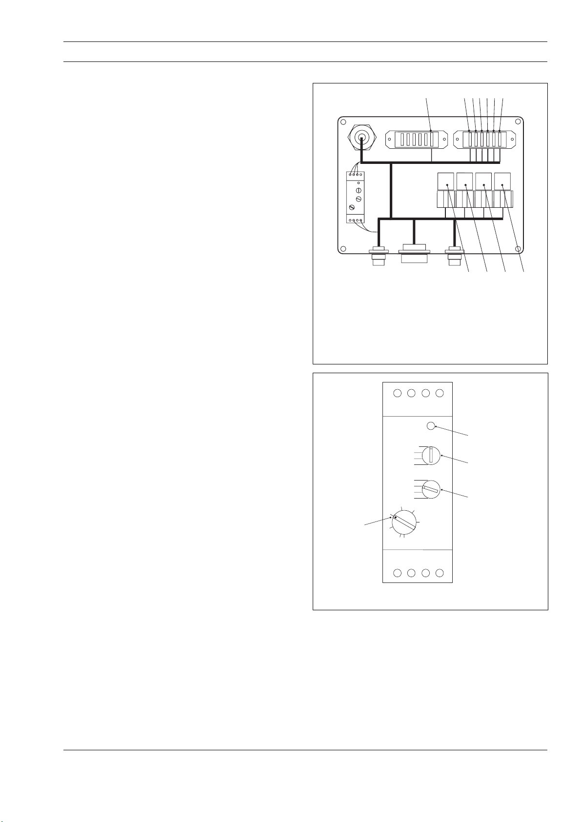
TRANSMISSION - C.E.C. 2
Section 120-0070
DESCRIPTION
The CEC–2 (Commercial Electronic Control, Version 2)
continually monitors the transmission and shift system
electrical components and warns the operator when a
problem develops. It also takes action to prevent
damage to the transmission, and provides the
serviceman with diagnostic capabilities so that
problems can be corrected quickly and easily.
The CEC–2 system used on this vehicle consists of a
gear shift selector, an electronic control unit (ECU),
throttle position sensor, transmission speed sensors (3
off), oil temperature sensor, solenoids, switches,
relays, circuit breakers, fuses, indicator lights and
wiring harnesses.
CEC–2 COMPONENTS
Description and Operation
Electronic Control Unit (ECU) - Contains an
electronic microcomputer. The ECU receives and
processes information defining: shift selector position,
throttle position, sump temperature, input speed,
turbine speed and transmission output speed. The ECU
uses this information to control the transmission
solenoids and valves, supply system status and
provide diagnostic information.
1 2 3456 7
ABCD
1. Control Fuse 6. Transmission ECU Fuse
2. Engine Master ECM Fuse 7. Transmission ECU Fuse
3. Engine Receiver ECM Fuse A. Ignition Sense Relay
4. Engine Master ECM Fuse B. Engine ECM Power Relay 1
5. Engine Receiver ECM Fuse C. Engine ECM Power Relay 2
D. Trans. ECU Power Relay
Fig.1 - Power Module
The ECU is programmed to take corrective action to
prevent damage to the transmission if a failure occurs
in the CEC–2 system and has diagnostic capabilities
which allow the serviceman to quickly find and repair or
replace a failed component. The ECU has 3
connectors; Blue - Transmission Connector, Gray Vehicle Connector, Black - Selector Connector.
Power Module - The Power Module is located on the
side of the battery box (Fig.1). The Power Module
contains ignition run fuses and relays, and a timer relay
for the shutdown function of the ECU. The ignition
fuses and relays open power to the ECU. On power
shut down the timer relay remains open for a 30
second period to allow the ECU to down load
information and close down properly (Fig. 2).
CEC–2 Interface Box - Provides the electrical link
between the vehicle harnesses and the CEC–2
harnesses. The interface box contains an ignition
signal fuse and function relays.
Gear Shift Selector - The shift selector is a remote
mounted lever type (Fig. 4). The gear shift selector is
connected to the ECU by a wiring harness. The shift
lever has 6 forward ranges and 2 reverse ranges, as
well as a neutral position. The shift selector has a
L. E. D.
Release delay
On-off pulse
SET DIAL TO '3'
LOCK IN POSITION
USING ARALDITE OR
SIMILAR
On-pulse
Off-pulse
0.6 - 6 sec
6 - 60 sec
0.6 - 6 min
6 - 60 min
4
3
2
1
5
6
SET DIAL TO 'Release delay'
SET DIAL TO '6 - 60 sec'
Fig.2 - Timer Relay Setting
single digit LED display, that during normal operation
will display the gear selected (Not gear attained).
Diagnostic information can be displayed on the single
digit LED display by pressing the diagnostic display
button. There is a hold override button that must be
pressed when shifting between R, N and D. The hold
override button is released when desired selector
position is reached. The selector lever can move freely
between D and the number ranges without pressing the
hold override button.
SM2128 02-02
1
Page 98
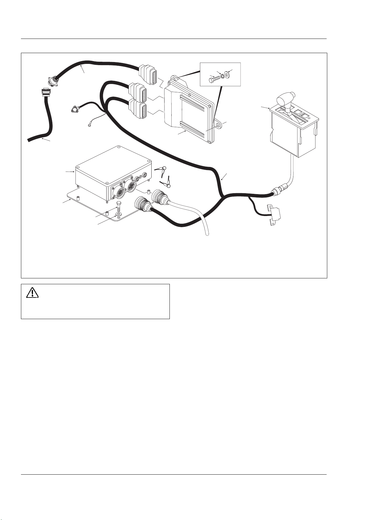
Transmission - C.E.C. 2
Section 120-0070
SM2657
TRANS. HARNESS
4
INTERFACE MODULE
3
CONNECTOR TO
TERMINATION
RESISTOR
12
6
1. Gear Shift Selector 5. Shift Control Harness 9. Bolt
2. E.C.U. 6. Mounting Plate 10. Lock Washer
3. Transmission Harness 7. Bolt 11. Washer
4. Transmission Harness 8. Washer 12. Interface Box
EARTH
2
7
8
10
9
E.C.U.
REF. CONSOLE HARNESS
11
1
SHIFT
SELECTOR
5
G
H
J
K L M
DIAGNOSTIC
CONNECTOR
Fig. 3 - C.E.C. 2 General Layout
WARNING
Do not allow the vehicle to coast in Neutral. This
practice can result in severe transmission damage.
The transmission upshifts and downshifts
automatically between first range and the highest range
selected on the range selector in direct response to
throttle position and transmission output speed.
When Reverse is selected the reverse alarm sounds
and the reverse light illuminates at the rear of the
vehicle. This feature warns personnel to the immediate
rear of the vehicle that the operator has shifted
to reverse.
When drive 'D' is selected, the transmission
automatically upshifts and downshifts through all six
forward ranges as required by loads and travel speeds.
Selecting a lower range (4th, 3rd etc.) limits the highest
range to which the transmission will automatically upshift.
If a lower range is selected while moving forward, the
transmission automatically downshifts sequential to
the selected lower range at maximum controlled engine
speeds. Downshifts will not occur until vehicle is
slowed by use of the service brakes and/or retarder.
When shifting from neutral to start from a standstill,
or to reverse direction, decelerate the engine to idle
speed. To move forward, select drive 'D' and accelerate
the engine to the vehicle load and speed requirements.
The transmission will automatically upshift from 1st
through 6th ranges as travel speed increases.
With the throttle fully depressed, and the mode
selection switch in the Power position, the
transmission upshifts to the next higher range when the
engine attains maximum rated speed, since maximum
power train output is needed under this condition.
At lower throttle settings where minimum power train
performance is required, the transmission will upshift
to the next higher range at less than maximum
rated engine speed.
Upgrades or soft spots might slow travel speed, even
at full throttle, requiring transmission downshifts to
maintain maximum powertrain performance. When this
occurs, the transmission downshifts automatically.
2
SM2128 02-02
Page 99
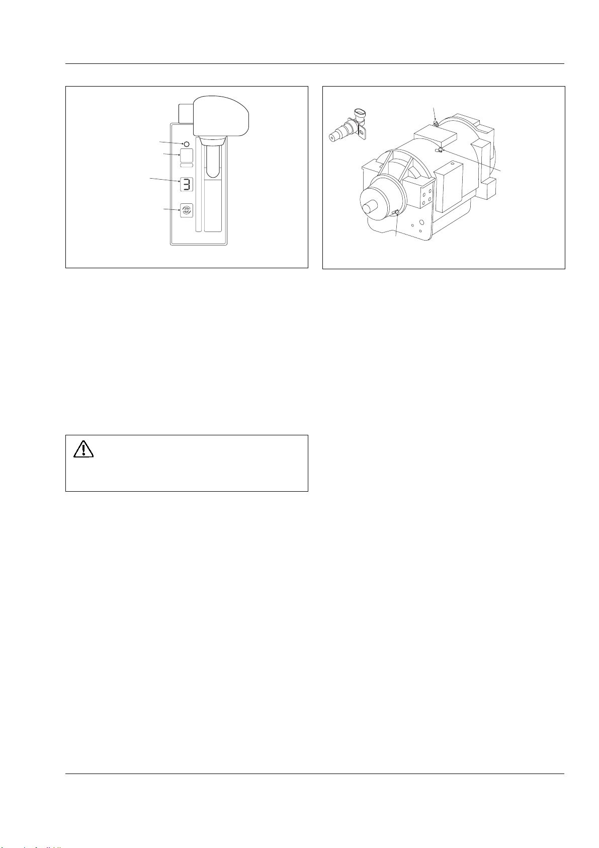
Transmission - C.E.C. 2
Section 120-0070
ENGINE SPEED SENSORSPEED SENSOR
MODE LIGHT
MODE BUTTON
DISPLAY
DIAGNOSTIC
BUTTON
MODE
1
2
3
4
5
D
N
R
1
R
2
Fig. 4 - Gear Shift Selector
Shift the transmission to the next lowest range if
transmission 'Hunting' or 'Shift Cycling' occurs.
When temporarily stopped, such as for yielding the
right-of-way to a loaded vehicle, the transmission can
be left in the selected range and the vehicle held
stationary with the service brakes.
However, when stopped for a more extended period
with the engine left running, shift the transmission to
neutral to avoid unnecessary heat buildup and apply
the parking brake.
WARNING
Always select Neutral and apply the parking brake
before leaving the operator’s seat.
TURBINE SPEED SENSOR
OUTPUT SPEED SENSOR
Fig. 5 - Speed Sensors Locations
the converter pump and turbine together as a single
unit and allows power to be transmitted mechanically
from the engine directly to the transmission gearing on
a 1:1 ratio. When the lockup clutch is disengaged, the
torque converter acts as a fluid coupling, multiplying
torque when engine speed is significantly higher than
transmission output shaft speed.
When the mode selection switch is in the Power
position, the ECU controls operation of the lockup
clutch according to signals received by the throttle
position sensor (giving engine speed as a percent of
throttle), the transmission output shaft speed sensor,
and range selector. The ECU may delay application of
the lockup clutch and allow torque multiplication by the
torque converter to take place until a balance is
achieved between engine speed and transmission
output shaft speed before activating the lockup clutch.
Speed Sensors - 3 off speed sensors (Fig. 5); Input,
Turbine and Output Speed, provide information to the
ECU. The input speed signal is generated by the gear
teeth on the top PTO gear. The turbine speed signal is
generated by the serrations on the tone wheel. The
output speed sensor signal is generated by a toothed
member attached to the output shaft. The speed ratios
between the various speed sensors allow the ECU to
determine if the transmission is in the selected range.
Hydraulic problems are detected by comparing the
speed sensor information for the current range to that
ranges speed sensor information programmed in the
ECU memory.
Mode Selection Switch - Gives the option to select
between transmission Power and Economy shift
schedules. The transmission must be in Neutral before
the switch will function.
The transmission torque converter is equipped with a
lockup clutch which, when engaged by the ECU, locks
SM2128 02-02
Power versus Economy Mode
The Power mode is designed for applications involving
heavy loads and hilly duty cycles where performance
rather than fuel economy is of prime importance.
The Economy mode is designed for applications
involving lighter loads and level duty cycles or where
fuel economy is more important than performance.
In the Economy mode, the ECU controls operation of
the lockup clutch with a timed, preprogrammed
schedule where in second through sixth gears the
lockup clutch is disengaged only long enough to allow
the torque converter’s fluid coupling to absorb shift
shock. Otherwise, the lockup clutch is engaged and no
torque multiplication takes place in second through
sixth gears.
Manual Mode Switch - The manual mode facility is
designed as a Service Technician facility to allow stall
checks and clutch pressure checks to be implemented
3
Page 100
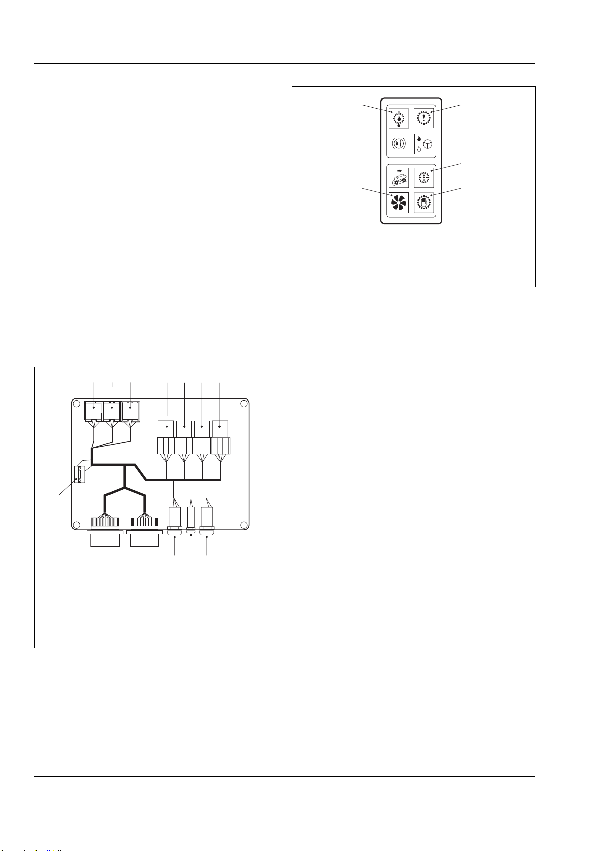
Transmission - C.E.C. 2
Section 120-0070
by Service Personnel, and permit movement of the
vehicle, if necessary, to a repair area. With the manual
mode switch in the 'On' position, the body up interlock
and hoist interlock pressure switch mechanisms are
disengaged! This allows unauthorised selection of
reverse or any forward gear with the body raised,
constituting a safety hazard. Operators must not use
the manual mode facility when working the vehicle! It is
recommended that the mode selection key is removed
from the unit and retained in a safe place until required
by Service personnel.
5
1
2
34
Note: The manual mode can only be used if the mode
selection switch is in the Power position and the
transmission is in neutral.
Manual Mode Warning Light - This light is located on
the front face of the CEC–2 interface box. The Manual
Mode Warning Light illuminates to alert the operator
when the transmission has been switched to operate in
the manual mode. The light should be 'Off' during
normal operation.
123 4567
8
CBA
1. Check Trans. Relay 6. Lock Up Off Relay
2. Neutral Start Relay 7. Converter Drive Relay
3. Reverse Relay 8. Ignition Sgnal Fuse
4. Body Up Relay A. Manual/Automatic Key
5. Delta P Relay B. Power/Economy Key
C. Manual Mode Light
Fig. 5- Interface Box
Check Trans Warning Light (Fig. 6) - Illuminates to
alert of a minor fault in the transmission control system
or abnormal transmission temperature. The light will
come 'On' when the ignition key switch is turned to
position '1' to provide a bulb and system check and
should go 'Off' a few seconds after the engine is
started and the transmission oil pressure rises.
The check trans warning light will come 'On' during
operation, if the ECU has detected a minor fault in an
1. Transmission Check Light 4. Converter Mode Light
2. Delta P Filter Restriction 5. Transmission Oil Temperature
3. Transmission Overspeed
Fig. 6 - Warning Lights
electrical component or abnormal transmission oil
temperature. If transmission oil temperature is too high,
stop the vehicle, select neutral 'N', and increase engine
speed to allow a greater flow of oil to the cooler until oil
temperature drops to normal operating range. In most
cases, a minor fault triggering the check trans warning
light will not prevent normal operation from continuing
but, depending on the nature of the problem, the ECU
could take action to protect the transmission from damage,
such as preventing operating in high gear ranges. If the
check trans light comes 'On', have the problem
diagnosed and corrected at the earliest opportunity.
Converter Mode Light - Illuminates when the
transmission is in torque converter drive. It goes 'Off'
when Lockup is engaged. In order to avoid
unnecessary waste of fuel, if traffic or other road
conditions permit, the operator should modify throttle
position, or gear held, to achieve a steady road speed
with the torque converter lockup engaged (light 'Off').
The Lockup relay in the interface box (Fig. 5) is also
activated by the 20 bar (290 psi) pressure switch on
the foot brake pedal. When this switch is activated the
converter in light will be illuminated due to the
transmission dropping out of converter lock up,
avoiding engine stall.
Transmission Overspeed Light - Illuminates when
the transmission ECU senses transmission RPM
exceeds 2350 RPM.
Electro-Hydraulic Valve Components: The CEC–2
electro-hydraulic valve bodies contain various solenoids
to control hydraulic pressure (Fig. 7). The solenoid
pressure, or lack of pressure, positions shift valves that
apply transmission clutches to produce the range selected
by the ECU inputs (Fig. 8). The ECU is connected to
the solenoids by a wiring harness, with multi-pin twistlock connectors at the valve bodies (Fig.9).
4
SM2128 02-02
 Loading...