

Page 1

SERIES AL5000
LIGHT TOWER
OPERATION/SERVICE
& PARTS MANUAL
California Proposition 65
WARNING
The engine exhaust from this product
contains chemicals known to the State of
California to cause cancer, birth defects or
other reproductive harm.
PO Box 3147 • Rock Hill, SC 29732 USA • Phone 803-324-3011
Toll Free 800-433-3026 Parts Department Fax 800-633-5534
1
Page 2

NOTES
2
Page 3

TABLE OF CONTENTS
Receiving and Set-up
Safety Precautions . . . . . . . . . . . . . . . . . . . . . . . . . . . . . . . . . . . . . . . 5-7
Check Out on Receipt/Delivery . . . . . . . . . . . . . . . . . . . . . . . . . . . . . 8
TEREX Amida Light Tower Model Coding System . . . . . . . . . . . . . . 9
Recommended Engine Oil. . . . . . . . . . . . . . . . . . . . . . . . . . . . . . . . . . 10
Operating Instructions
Light Tower Operating Instructions. . . . . . . . . . . . . . . . . . . . . . . . . . . 11-14
Criteria for Replacement of Wire Rope . . . . . . . . . . . . . . . . . . . . . . . . 15-17
Engine (see manufacturer’s handbook)
Generator (see manufacturer’s handbook)
Parts Identification Drawings
Trailer and Related Parts. . . . . . . . . . . . . . . . . . . . . . . . . . . . . . . . . . . 20-21
Axle and Wheels . . . . . . . . . . . . . . . . . . . . . . . . . . . . . . . . . . . . . . . . . 22
Cabinet and Attachments . . . . . . . . . . . . . . . . . . . . . . . . . . . . . . . . . . 23-25
Tower and Related Parts. . . . . . . . . . . . . . . . . . . . . . . . . . . . . . . . . . . 26-34
Engine and Generator . . . . . . . . . . . . . . . . . . . . . . . . . . . . . . . . . . . . . 35-40
Electrical Box . . . . . . . . . . . . . . . . . . . . . . . . . . . . . . . . . . . . . . . . . . . 41
Floodlight Fixtures / Ballasts . . . . . . . . . . . . . . . . . . . . . . . . . . . . . . . . 42-43
Hitches . . . . . . . . . . . . . . . . . . . . . . . . . . . . . . . . . . . . . . . . . . . . . . . . 44
Electric Winch. . . . . . . . . . . . . . . . . . . . . . . . . . . . . . . . . . . . . . . . . . . 45
Running Lights . . . . . . . . . . . . . . . . . . . . . . . . . . . . . . . . . . . . . . . . . . 46
Wiring Diagrams
Fixture with Joy Connector (MH or TH) . . . . . . . . . . . . . . . . . . . . . . 47
Metal Halide Ballast with Joy Connector . . . . . . . . . . . . . . . . . . . . . . 48
High Pressure Sodium Ballast with Joy Connector . . . . . . . . . . . . . . . 49
AC Wiring . . . . . . . . . . . . . . . . . . . . . . . . . . . . . . . . . . . . . . . . . . . . . . 50
DC Wiring . . . . . . . . . . . . . . . . . . . . . . . . . . . . . . . . . . . . . . . . . . . . . . 51
Troubleshooting Guide
Specifications, Routine Maintenance, Wind Loading . . . . . . . . . . . . . 52-55
Broken Cable Replacement Procedure . . . . . . . . . . . . . . . . . . . . . . . . 56-57
Light Fixture Troubleshooting . . . . . . . . . . . . . . . . . . . . . . . . . . . . . . . 58-60
TEREX Amida Numbered Wiring System . . . . . . . . . . . . . . . . . . . . . 61
Generator Bearing Inspection . . . . . . . . . . . . . . . . . . . . . . . . . . . . . . . 62
Engine (refer to manufacturer’s handbook)
Generator (refer to manufacturer’s handbook)
Warranty Information
Warranty Procedure . . . . . . . . . . . . . . . . . . . . . . . . . . . . . . . . . . . . . . 63
Warranty . . . . . . . . . . . . . . . . . . . . . . . . . . . . . . . . . . . . . . . . . . . . . . . 64
3
Page 4

NOTES
4
Page 5

SAFETY PRECAUTIONS
The following symbols in this manual signal potentially dangerous conditions to the operator or equipment.
Read this manual carefully. Know when unsafe conditions can exist. Then, take necessary steps to protect
personnel, as well as equipment.
WARNING: TEREX Amida uses this symbol throughout this manual to warn of possible fatal injury.
CAUTION: TEREX Amida uses this symbol to point out potential damage to equipment.
Lamps, fuels, electrical equipment, batteries, exhaust gases, loose fasteners, and moving parts present potential
hazards that could result in serious personal injury. Be diligent in following the procedures recommended
below . Also, observe the many additional general safety rules practiced by trained operation and maintenance
personnel in your company and industry. CAUTION: Always wear a hard hat when operating the light
tower!
• Guard Against Electrical Shock
This light tower also has provisions for producing high voltage electricity (up to 480 volts) that can produce
a fatal shock to a person who accidentally places their self in the electrical circuit.
Use every precaution to avoid contact with the high voltage electric circuit.
Beware of a cut or damaged power cord. Replace immediately.
Take extra precautions when troubleshooting electrical problems:
• When troubleshooting indicates a malfunction in the high voltage AC system, then pass the troubleshooting
task on to a qualified and trained electrician.
• Disconnect electrical power and turn off engine before removing protective covers on high voltage enclosures.
• Understand that the electrical circuits in this light tower complete their paths back to the generator within
the equipment. The neutral conductor at the generator is bonded to the equipment frame.
• Ground wires within the system are also bonded to the equipment frame.
• Only use a multimeter (or voltmeter) with two well-insulated probes rated for 750 volts.
• Keep one hand in your pocket when touching the multimeter probe to hot conductors. This will prevent
electricity from passing into one hand and out the other, a path that takes the electricity across the heart.
Always disconnect power from the circuit being measured before connecting test leads to high voltage
points.
• Do not try to position both probes at once. Instead, clamp the common insulated alligator clip to a neutral
wire and then probe for voltages with the other probe.
• Never clamp to a hot wire since a severe shock could be received by contact with the other probe.
• Do not use a multimeter with leads or probes that have damaged insulation.
• Inspect the ground cable between the generator set and the frame. If damaged, replace immediately.
• Treat all conductors as potentially hot, especially when troubleshooting malfunctioning equipment. Jewelry
should be removed before working around live conductors.
• Proceed through the circuitry systematically , operating only one section at a time.
• Use tools with insulated handles when working within the reach of live conductors.
• Maintain a good footing. If you slip, or a tool drops, do not grab for it if live conductors are within reach.
• Concentrate on the task until the danger from high voltage is removed.
5
Page 6

• Guard Against Battery Hazards
Lead acid batteries can be dangerous. The sulfuric acid in the battery can cause severe skin and eye burns.
The hydrogen gas emitted during charging can explode if an arc or flame is present near the battery. Use
precautions to prevent acid burns or explosive conditions.
Do not smoke while servicing batteries.
Do not allow tools to touch battery terminals and create an arc. Do not test battery voltage by setting up a
brief arc at the terminals. Use a multimeter instead.
Disconnect the negative terminal of the battery when working on the engine or other parts to prevent acci-
dental arcing. Disconnect the negative cable at the end away from the battery.
Always wear eye protection when servicing the battery .
When charging the battery, do not remove the vent caps.
If acid does get on skin or in eyes, immediately flush under running water, and then obtain medical help as
soon as possible.
• Guard Against Fire Hazard
Use caution with diesel fuel and motor oil because of fire hazards.
Do not fill fuel tank while engine is running.
Do not smoke or use open flame near the unit or the fuel tank.
Be sure the fuel supply has a positive shut-off valve.
Do not replace fuel lines with materials different from those supplied as original equipment.
Have a fire extinguisher nearby. Be sure the extinguisher is properly maintained and be familiar with its
proper use. Extinguishers rated ABC by the NFPA are appropriate for all applications.
Keep this unit clean of excessive build-up of spilled oil and fuel. Accumulated oil and fuel can cause over-
heating and subsequent engine damage as well as present a fire hazard.
Remember that EXHAUST GASES ARE TOXIC. WARNING: DO NOT USE INDOORS unless
properly ventilated. Provide an adequate exhaust system to properly expel discharged gases. Check exhaust
system regularly for leaks. Ensure periodically that the exhaust manifolds are secure and not warped. Make
sure the unit is well ventilated.
• Protect The Environment And Practice Good Industrial Hygiene
Prevent pollution by catching used oil in a container for proper disposal.
Wash hands to remove oil and fuel. Practice good industrial hygiene.
Maintain an adequate exhaust system to properly expel discharged gases. Check the exhaust system regu-
larly for leaks.
6
Page 7

• Do Not Touch Hot Parts
The exhaust manifold and tailpipe are very hot. Parts of the engine are also hot. Avoid touching hot parts of
the engine or tailpipe. Use protective gloves when handling hot parts.
• Be Alert And Attentive To The T ask
Read the safety instructions and operating procedures before attempting to troubleshoot or work on this unit.
Also read the engine manual, which is a separate booklet that is provided with this manual.
Do not work on this equipment when mentally or physically fatigued.
Do not work on this equipment when under the influence of performance impairing drugs or alcohol.
If this manual becomes lost, order a new one from TEREX-Amida so future operation and maintenance
personnel may read these instructions.
• Beware of Moving Parts
Avoid being hit or pinched by the moving parts of this unit.
Loose jackets, shirts, neckties, or sleeves should not be worn while working or running a unit.
Only remove guards or protective devices from unit temporarily to gain access for maintenance. Always
replace guards and protective devices promptly .
Keep your hands away from moving parts. Particularly, be sure to keep hands clear of the blower and
alternator belts when the engine is running.
• Beware of Traffic Hazards
Stand clear of traffic when starting or checking the unit along the road.
Check the fuel tank, oil pan, and fuel and oil lines for leaks that would spill fuel or oil on the road.
Check fasteners and mounting brackets periodically to insure all are tight and nothing is in danger of falling
off during transit.
• Use Only Equal Replacement Parts
When a part fails and needs to be replaced only use equivalent size, length, thread, grade, and material.
Replace stainless steel fasteners with stainless steel fasteners. The engine may use metric or SAE bolts, but
all other bolts are generally SAE thread. Be sure to use Grade 8 bolts and nuts to mount the genset to the trailer.
Replace the fuel and oil hoses with items of equal material, diameter and length.
Contact the manufacturer, TEREX-Amida, regarding replacement parts to ensure a correct repair.
• Use Caution Working Near Lamps
Metal halide lamps produce short wave ultra-violet radiation and can cause serious skin burn, or eye inflammation if the outer envelope of the lamp is broken or punctured. Do not use where people will remain for
more than a few minutes unless adequate shielding or other safety precautions are used.
7
Page 8

CHECK OUT ON RECEIPT OF DELIVERY:
The tower will be serviced, tested and ready for operation when received except for export units
and skid mount units which are knocked down for shipping (export units are also shipped with
dry batteries). Amida recommends the following checks:
A. INSURE THERE IS NO FREIGHT HANDLING DAMAGE which should be charged against
the carrier.
B. Insure the manuals are in the pocket provided inside the unit.
C. Review the manuals for safety and operating procedures.
D. Check the engine oil, coolant (if liquid cooled) and fuel levels.
E. Operate the tower in accordance with operating instructions.
EXPORT: Assemble according to the instructions enclosed.
8
Page 9

LIGHT TOWER MODEL CODING SYSTEM
IMPORTANT
WHEN REQUESTING TECHNICAL HELP AND ORDERING REPLACEMENT PARTS THE MODEL AND
SERIAL NUMBER ARE NECESSARY.
REFER TO THE AMIDA SERIAL NUMBER TAG ON THE UNIT FOR CORRECT MODEL NUMBER AND
SERIAL NUMBER.
MODEL NUMBER IDENTIFICATION
Samp1e:
Light Tower Product Line LT5 080 D 4 MH CE
T ower Series
AL4000 (AL4) = 30 Foot Basic Tower with winch in cabinet
AL5000 (ALS) = 30 Foot Basic Tower with in-cabinet light
storage and door insulation
5000 (5) =30 Foot Enhanced Cable Tower
2000 (2) =Model 5000 with extra corrosion protection
LT5000 (LT5) = 30 Foot Deluxe Cable Tower w/optional Acoustic
Enclosure and Complete Instrumentation
LT2000 (LT2) = Model LT5000 with Extra Corrosion Protection
7000 (7) = 30 Foot Enhanced Hydraulic Tower
LT7000 (LT7) = 30 Foot Deluxe Hydraulic Tower w/optional Acoustic
Enclosure and Complete Instrumentation
KW Rating
(080 is 8.0 kW)
Diesel (D) or Gas (G)
Number of Lights
T ype of Lights
European Version (AL4000 Only)
HPS = High Pressure Sodium
MH= Metal Halide
MV= Mercury Vapor
TH= Tungsten Halogen
9
Page 10

RECOMMENDED ENGINE OIL & FUEL
KUBOTA D905 DIESEL ENGINE
Engine oil should be MIL-L-2104B/MIL-L-2104C or have properties of API designation of CC/SF or CD/SF.
Change the type of engine oil according to the ambient operating temperature:
Above 86°F SAE 30
32°F to 77°F SAE20
Below 32°F SAE10
SAE 10W-30
Use #2 diesel fuel.
LISTER-PETTER LPW3/LPA3/LPW4/LPWT4 DIESEL ENGINES
Engine oil should be MIL-L-2104C or have properties of API designation of CC/SF or CD/SF. Use CC grade
oil for the initial break-in period. Multi-viscosity oils (such as 10W-40) should not be used at temperatures
above 32°F. Be sure to use the correct oil viscosity for the weather you are experiencing. When this engine
left the factory, it was filled with engine oil as specified on this page.
Change the type of engine oil according to the ambient operating temperature:
86°F and warmer SAE30
Between 39°F & 86°F SAE20/20W-SAE 15W/40
Between 5°F & 39°F SAE 10W
Below 5°F SAE 5W
Use #2 diesel fuel above 5°F, #1 diesel fuel below 5°F.
NOTES:
1. The temperatures in the table are the ambient temperature at the time when the engine is started.
However, if the running ambient temperatures are much higher than the starting temperatures, a compromise must be struck and a higher viscosity oil and fuel used, provided they have a suitable specification.
2. MIL-L-2104B or MIL-L-2104C or API CD oils are recommended, particularly in high temperature
applications. They must also be used if the sulfur content of the fuel exceeds 0.5%.
3. CAUTION: The use of Series III oils in new , or overhauled naturally aspirated engines can inhibit breakin and give rise to cylinder bore glazing in engines on low duty cycles. Therefore, they should not be used
for the first fill in new or newly overhauled naturally aspirated engines, but may be used advantageously
after the first 250 hours, when the engine is operating in hot ambient temperatures and high load factor.
4. Always use a reputable brand of diesel fuel. The sulfur content should be below 0.5% (higher sulfur content would
require more frequent oil changes). At low ambient temperatures (below freezing), use winter grade diesel fuel. At
higher temperatures, use summer grade diesel fuel. Observe strict cleanliness when filling the fuel tank.
5. Check the engine oil level before starting the engine or more than five minutes after it has been
stopped. Remove the dipstick, wipe clean, reinsert it, take it out again, and check the oil level. If the
oil level is too low, remove the oil plug and add new oil to the FULL line on the dipstick.
10
Page 11

MODEL AL5000
OPERATING INSTRUCTIONS
I M P O R T A N T: READ ALL DIRECTIONS IN MANUAL CAREFULLY
BEFORE OPERATING EQUIPMENT
WARNING CAUTION DO NOT RAISE TOWER IN THE VICINITY OF
OVERHEAD POWER LINES!
O P E R A T I N G I N S T R U C T I O N S
I. MOVE LIGHT TOWER TO DESIRED LOCATION KEEPING THE FOLLOWING IN MIND:
A. The light tower should not be placed where those working under the light are either:
1) Forced to look into the light regularly .
2) Forced to work with their backs to the light (shadows will block the light from the work area).
B. The area where the tower is positioned should be relatively level.
C. The light tower should be located on the same level or on ground higher than the area being lighted
(higher light mounting heights reduce the shadow length).
D. Unit should be level to ensure smooth trouble-free tower telescoping. Tower may not telescope down
properly when unit is not level.
II. UNHITCH FROM THE TOWING VEHICLE AS FOLLOWS:
A. Engage the trailer braking system, especially if trailer is not on level ground. CAUTION: If electrical
or manual braking system is not supplied, chock the wheels instead.
B. Swing the tongue jack into position and raise the tongue off the towing vehicle.
III. LEVEL THE TRAILER, USING THE JACKS AS FOLLOWS:
A. Extend the rear outriggers until the springs lock into place. Swing the jack on each outrigger into verti-
cal position.
B. Start at the highest jack position. Rotate the jack handle until the jack foot touches the ground.
C. Raise the other jacks to level trailer…WARNING…CAUTION…insure that the rear jacks are down to
prevent the tower from tipping over backwards when raised.
IV. DRIVE GROUNDING ROD INTO EARTH
11
Page 12
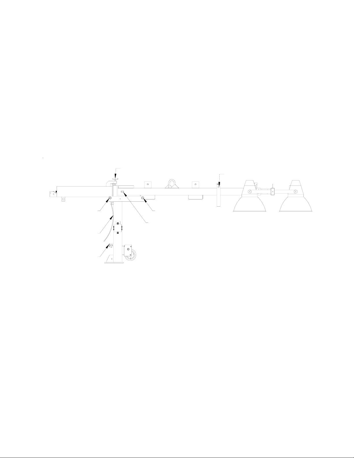
IV. INSTALL THE FLOODLIGHTS ON THE CROSSBEAM
A. Remove the light fixtures from the tower by removing detent pin and rotating the clamp to free the
lights. Install them on the cross arm studs with the lens facing the ground.
B. The cord on the fixture should be on the side closest to the trailer so the cord entry is beneath the fixture when
the tower is raised ( this reduces moisture problems and ensures the water weep hole in the fixture is down).
C. Set the vertical aim for each light fixture by adjusting the light fixtures and tightening the lower bolt.
D. Set the spread between the light fixtures horizontal aiming by adjusting the fixtures and tightening the
wing nut.
E. The unit may be transported with the light fixtures mounted on the cross-arm if they are pointed toward
the ground.
"T" BOLT
TRAVEL LOCKING PIN
HORIZONTAL LOCKING PIN
KICK-OUT SPRING
VERTICAL LOCKING PIN
HORIZONTAL LOCKING PIN
TELESCOPING LOCKING PIN
V. RAISING THE TOWER (refer to drawing above)
A. Remove the tower travel-locking pin from the cradle at the rear of the cabinet.
B. Aim the fixture, both horizontally and vertically, to the estimated angles that will light the work area.
C. Using the winch, raise the tower to the vertical position. The tower-locking pin at the base of the pivot
post will lock automatically and you will hear it “snap” into place. Insert manual pin into locking
device.
D. Release the tension on the cable by backing the winch off slightly and pull the telescoping locking pin on
the galvanized tower section. Hold this out while turning the winch to raise the tower. After the tower
has telescoped slightly, the locking pin can be released. Raise the tower to the desired height.
CAUTION: DO NOT A TTEMPT TO LEAN THE TOWER DOWN WHEN IT IS EXTENDEDSERIOUS DAMAGE MA Y OCCUR!
12
Page 13

IV. START THE ENGINE / GENERATOR SET
A. CAUTION: Ensure the circuit breakers are turned “OFF”. This prevents the engine from starting under
load and prevents electrical equipment from being subjected to improper voltage and frequency .
B. Check the oil, fuel, and coolant (if liquid cooled) levels. If the fuel tank is empty, it may be necessary to
bleed the fuel line after filling the tank (see engine instruction book for procedure).
C. Turn the ignition switch to the “RUN” position (see diagram below). Press the preheat push button for a
maximum of 7 seconds. Do not engage the preheat button longer than the time specified or damage
may occur.
D. Turn the ignition switch to the “START” position to engage the engine. After the engine starts, release
the switch so that it returns to the “RUN” position. Let the engine come up to speed and stabilize (review the engine operating procedures in the manufacturer’s handbook).
E. T urn on the main circuit breaker.
V. TURN ON THE FLOODLIGHTS
A. Turn the circuit breakers “ON” and check to insure all lamps come on. Allow a minimum of two (2)
minutes for lamps to reach full luminance.
B. If required, rotate the tower to aim the lights as desired. Tighten the tower rotating locking bolt.
C. Adjust the tower vertically and adjust lighting direction of individual fixtures if required.
VI. LOWERING THE TOWER TO TRAVELING POSITION
A. Loosen rotating lock.
B. Using the winch, telescope the tower down to its fully retracted position until the telescoping locking pin
snaps into place.
D. CAUTION: Ensure that the telescoping locking pin locks before pulling the tower locking pin at the
bottom of the pivot post. This ensures the tower is completely lowered and cannot be damaged by
telescoping out while in the travel position.
E. Rotate the tower so that the groove in the galvanized ring at the pivot is pointing to the rear of the trailer
so that the tower can be lowered into the travel position.
13
Page 14

Operating Procedures (cont’d)
F. Pull the vertical locking-pin at the base of the pivot post (the kick-out spring should provide sufficient
pressure to start the tower pivoting over).
G. Let out on the winch cable to lower the tower into the cradle.
H. Insert the rear tower horizontal travel-locking pin into the cradle.
VII. TURN OFF FLOODLIGHTS
A. If operating, turn light circuit breakers off.
B. Turn engine switch to “OFF” to shut down the engine.
CAUTION: Do not shut down engine prior to turning lights off.
C. CAUTION: Allow lamps to cool at least ten (10) minutes before moving the tower to avoid breaking
lamps.
VIII. RELOCATING LIGHT TOWER TO NEW LOCATION
A. Insure that tower has been properly lowered (see section VI) and locking pins are engaged.
B. Insure all fixtures are pointed toward the ground, or mounted on the fixture storage brackets on the lower
tower section.
C. CAUTION: All jacks must be raised and all outriggers locked into travel position.
D. Insure that the coupler is properly secured to the towing vehicle and attached safety chains (if supplied).
Release any manual braking mechanism (if supplied).
E. Do not tow at excessive speeds (60 mph – 100-kmh maximum) as the weight of the light tower can
cause loss of vehicle control, especially under emergency stopping conditions. The standard trailer has
no towing brakes; therefore allow extra distance for stopping.
VI. USE OF LIGHT TOWER AUXILIARY POWER
A. One (1) 30amp/240v Twist-Lock and (1) 20 amp/120v receptacles are provided for auxiliary power.
B. Total auxiliary power cannot exceed main circuit breaker rating. Each lamp operating consumes 10
amps of current @ 120 volts ac.
C. Before plugging in auxiliary power cords, feed them up through the trailer frame and attach to recep-
tacles. Close the cabinet doors to protect control panel and other components from weather (see Miscellaneous Specifications and Routine Maintenance section for power control details).
14
Page 15

CRITERIA FOR REPLACEMENT OF WIRE ROPE – TEREX-AMIDA LIGHT TOWERS
The wire ropes used to raise and lower the masts on a TEREX-Amida Light Tower are probably some of the most
important mechanical parts used in day-to-day operation of the machinery. It is therefore very important that the cables be
inspected on a frequent basis (once a month) for wear and tear, and immediately in the event of possible damage due to
operator error in using the winch, or possible damage from other equipment.
NORMAL WEAR AND TEAR
When used properly, the wire ropes should give years of trouble-free service, depending on how often the masts are
raised and lowered. The rule of thumb at TEREX-Amida is that if the tower is raised and lowered an average of once
per day, that the cables should be replaced every two years of service.
NORMAL INSPECTION
The wire ropes are constructed of 7 strands of 19 plow steel wires each twisted together, and then the assembly galvanized to resist corrosion. Using a wadded-up cloth or heavy leather gloves (to avoid being pricked by a broken wire), run
a hand up and down a length of the cable. If any exterior wires are broken, they will lift up from main body of the cable
and become visible. For any given 1 foot of cable length; if there are 4 or more wires each, on any 2 or more strands
broken, the suspect rope should be replaced immediately.
OPERA TOR ERROR – OTHER MACHINERY DAMAGE
One of the most common reasons for failure of a Light Tower wire rope is due to operator error in using the winch, or
damage to the cable by tools or other machinery. The most common operator error happens when the mast is telescoping
down. When the upper telescoping lock engages, the operator does not pull the lower pivot lock out (located on the
tower base) and keeps on cranking the winch. This results in the cable becoming loose around the drum due to the
tower not pivoting down. This can result in three problems: the loose cable can get trapped underneath itself, resulting
in a sudden or partial “drop” of the mast when the loose section releases at a later time, thus damaging the cable; or the
cable can jump off the winch drum and be damaged by the gears of the winch. The loose cable can also cause the drum to
spin to take up the slack cable. If there is enough friction in the threaded parts of the winch, the drum can cause the crank
handle to start spinning. This can cause the tower to “freefall” and the results can be catastrophic for anyone standing
underneath the tower. A spinning crank handle can also break bones.Other reasons damage can occur are due to some
outside force such as forklift blade nicking or crushing a cable when moving a unit, or an accidental blow or damage by a
hand tool, etc.
DAMAGE INSPECTION
If any nicks (partial strand cut through), kinks (permanent bends), or weld spatter on the cable (from field service) are
observed, the suspect wire rope should be changed immediately.
If there is a crushed spot somewhere on the wire rope, it should be replaced only if the width of the crushed spot exceeds
1-1/4 times the nominal diameter of the cable (5/16” on a 1/4” cable, and 7/32” on a 3/16” cable), or if there are broken
wires at the point of damage.
15
Page 16

NOTES
16
Page 17
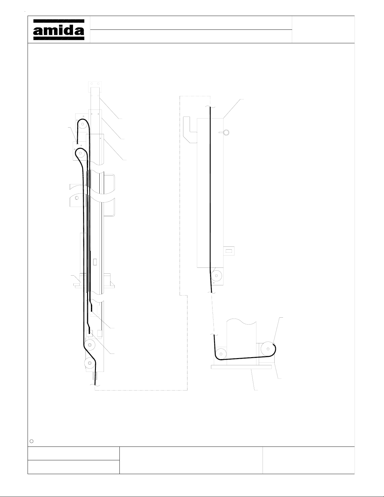
Cable 2
Point B
Model:
Title:
AL5000 LIGHT TOWER
Cable Replacement Diagram
2" Section
3" Section
4" Section
Page:
6" Round Tube
"Hat" Section
c Amida Industries, Inc. 1999
Created:
By:
2-2-99
Spectrum
Cable 2 (109070)
Point A
Cable 1 (109065)
Point A
Revised:
a)
b)
Cable 1
Point B
Winch
Tower
Base
d)
e)
f)c)
Document:
17
Page 18

NOTES
18
Page 19

PARTS MANUAL
19
Page 20
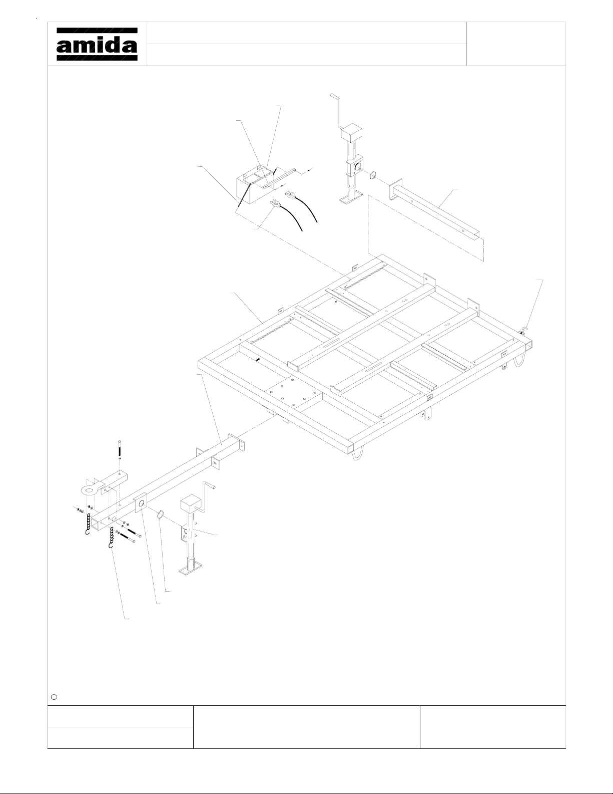
Model: Page:
Title:
174160, Battery Hold-Down
182330, Battery Hold-Dow n R od
160273, Battery Cable Set
124800, Trailer Frame
AL5000 LIGHT TOWER
Trailer Frame/Tongue/Outriggers
160110, Battery
114612, Outrigger
109150, Plunger Kit
124470, Tongue
840222, Jack Snap Ring
840221, Jack Bracket
110870, Safety Chain
841430, Jack
By:
c Amida Industries, Inc. 1999
2-2-99
Spectrum
a)
b)
c) f)
d)
e)
Document:Revised:Created:
20
Page 21
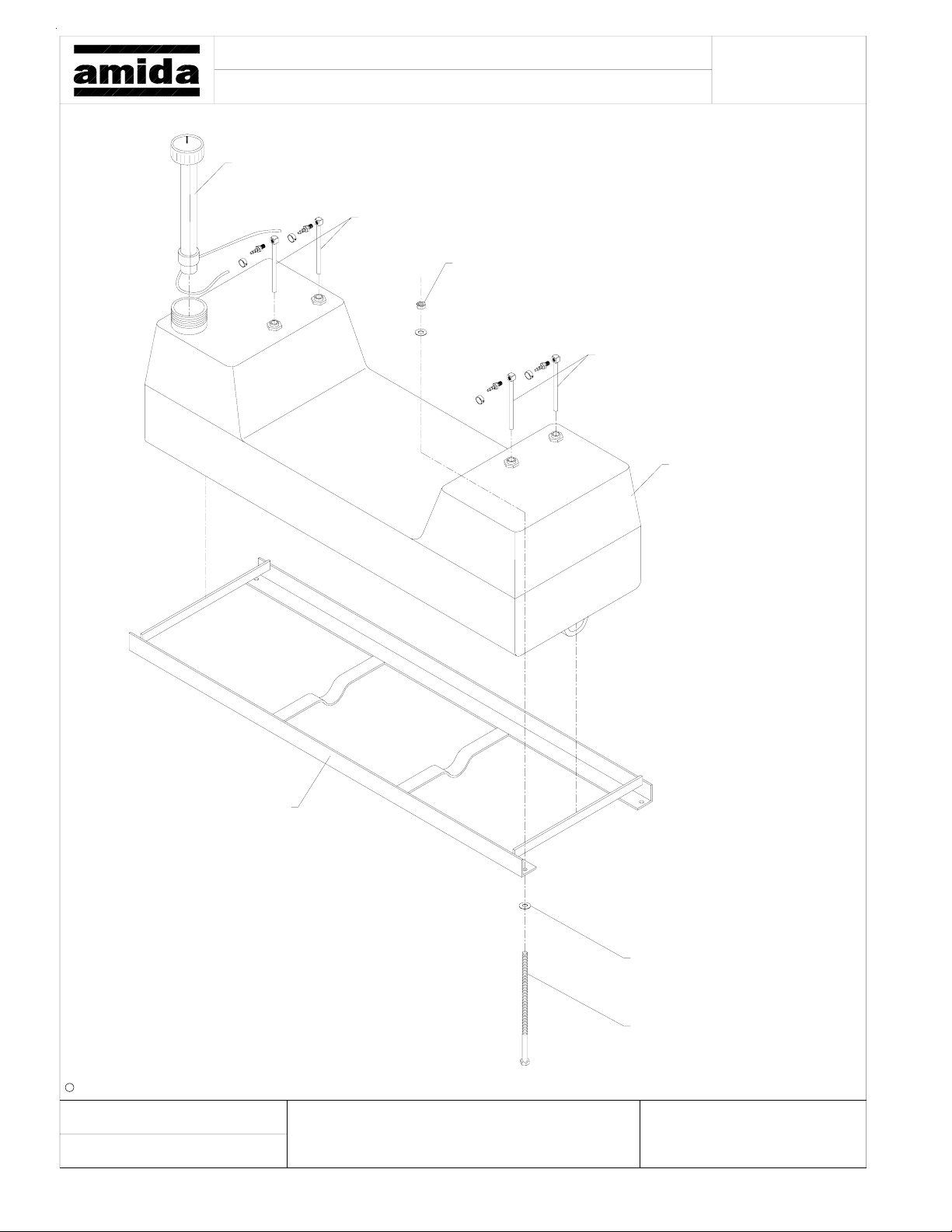
Model: Page:
Title:
AL5000 LIGHT TOWER
Fuel Tank
741715, Cap & Gauge
Roadside Return & Supply
(4) 990170, Lock Nut
Curbside Return & Supply
741701, 30 Gal. Fuel Tank
c Amida Industries, Inc. 1999
By:
114720, Fuel Mounting
Bracket
2-2-99
Spectrum
a)
b)
c) f)
21
(8) 990080, Flat Washer
(4) 992310, 3/16"-16x6" Bolt
d)
e)
Document:Revised:Created:
Page 22
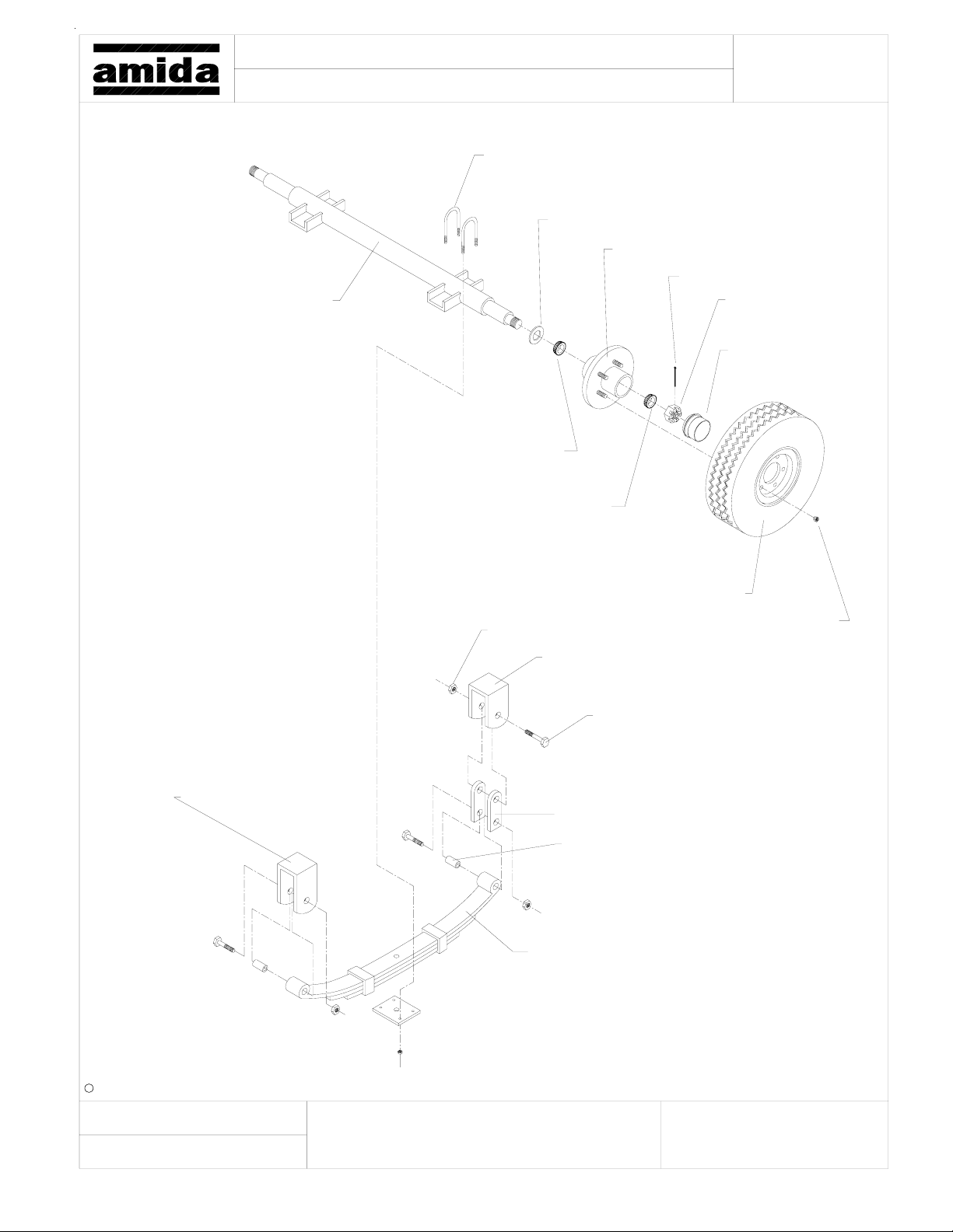
Title:
Note: Axle Ass'y w/o Tires- 840377
834339, Axle
AL5000 LIGHT TOWER
Axle Assy.
(2) 834267, U-Bolt Kit
834225, Grease Seal
834226, Inner Bearing
Page:Model:
834220, Hub Assy.
834255, Cott e r Pin
834250, Spindle Nut
834228, Grease Cap
841051, Axle Front Hanger
834227, Outer Bearing
841060, Tire & Wheel Mounted
(3) 840395, Axle Spring Nut
840392, Axle Rear Hanger
841473, Axle Shackle
(2) 834246, Spring Eye Bushing
834211, Leaf Spring
840376, Lug Nut
(3) 840394, Axle Spring Bolt
c Amida Industries, Inc. 1999
Created:
By:
2-2-99
Spectrum
Revised: Document:
a)
d)
e)b)
f)c)
22
Page 23
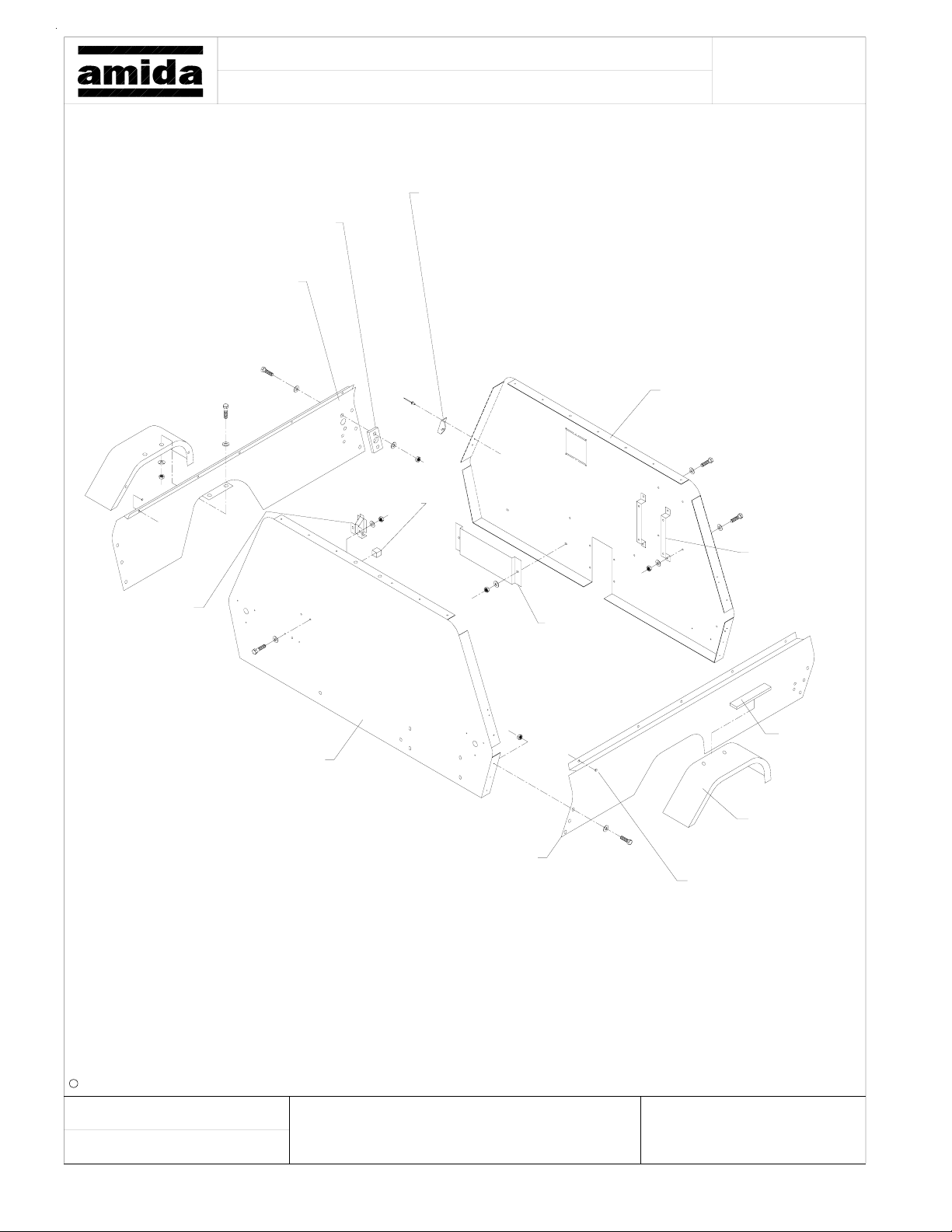
Model: Page:
Title:
184150, Winch Handle Bush.
189860, Cabinet, Roadside
AL5000 LIGHT TOWER
Cabinet Assy.
(4) 796432, Door Shock Bracket
124420
Ground Rod
Storage Tube
189820, Cabinet, Front
Radiator Overflow
Bracket
124190, Cabinet, Rear
(2) 189390
Elec. Box
Mtg. Bracket
176370
Literature
Rack
(2) 930950
Weatherstrip
Adhesive
(2) 123490
Fender
189870, Cabinet, Curbside
(10) 791840
Rubber Bumper
By:
c Amida Industries, Inc. 1999
2-2-99
Spectrum
a)
b)
c) f)
23
d)
e)
Document:Revised:Created:
Page 24
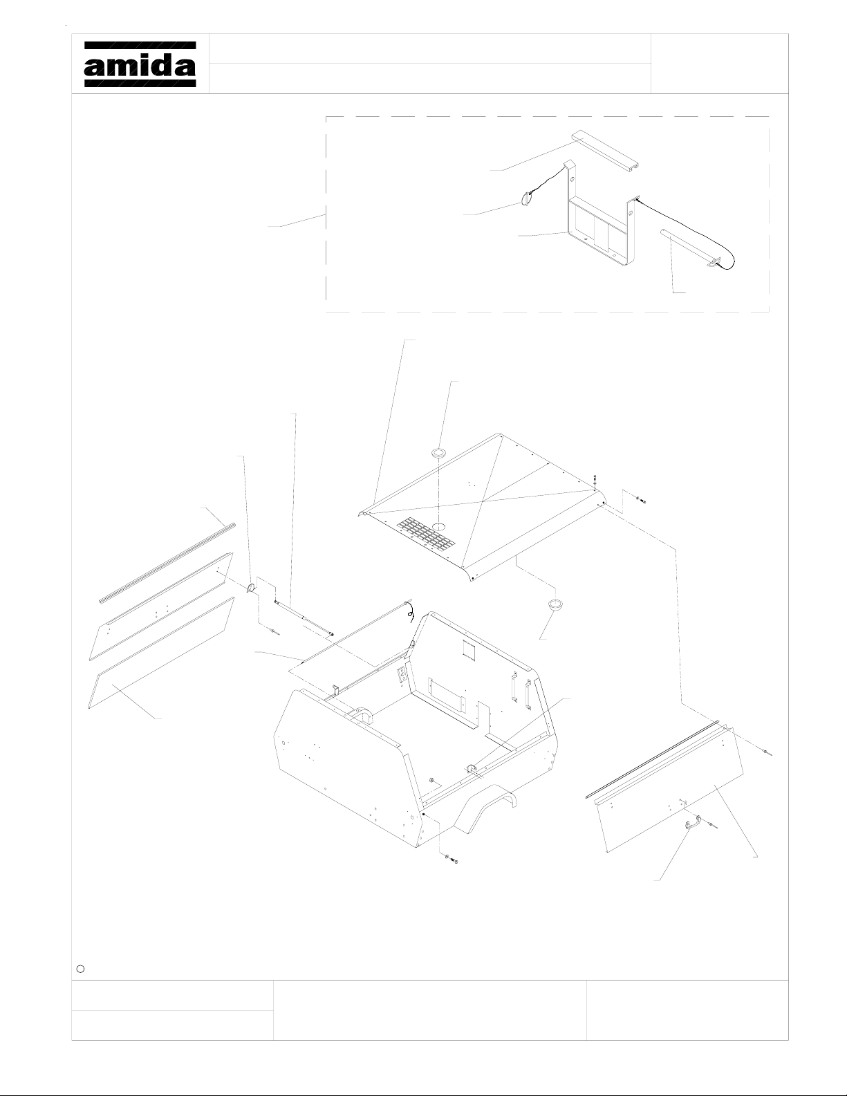
Model: Page:
Title:
AL5000 LIGHT TOWER
Cabinet Assy.-116650
720220, Bumper
116180, Rear
Tower Support
(4) 796438, Gas Shock
(4) 796432
Door Shock
Bracket
(2) 796730
Hinge
790540, Pin
124460, Tower Support Cradle
123680, Pin
189840, Cabinet Top
974680, Plastic Plug
By:
113390
684030, Dome Light
Ground Rod
(2) 189795,
(2) 189920,
Door Hasp
Door Foam
Insulation
(2) 189851
(2) 790940, Handle
c Amida Industries, Inc. 1999
2-2-99
Spectrum
a)
b)
c) f)
d)
e)
Document:Revised:Created:
Cabinet Door
24
Page 25
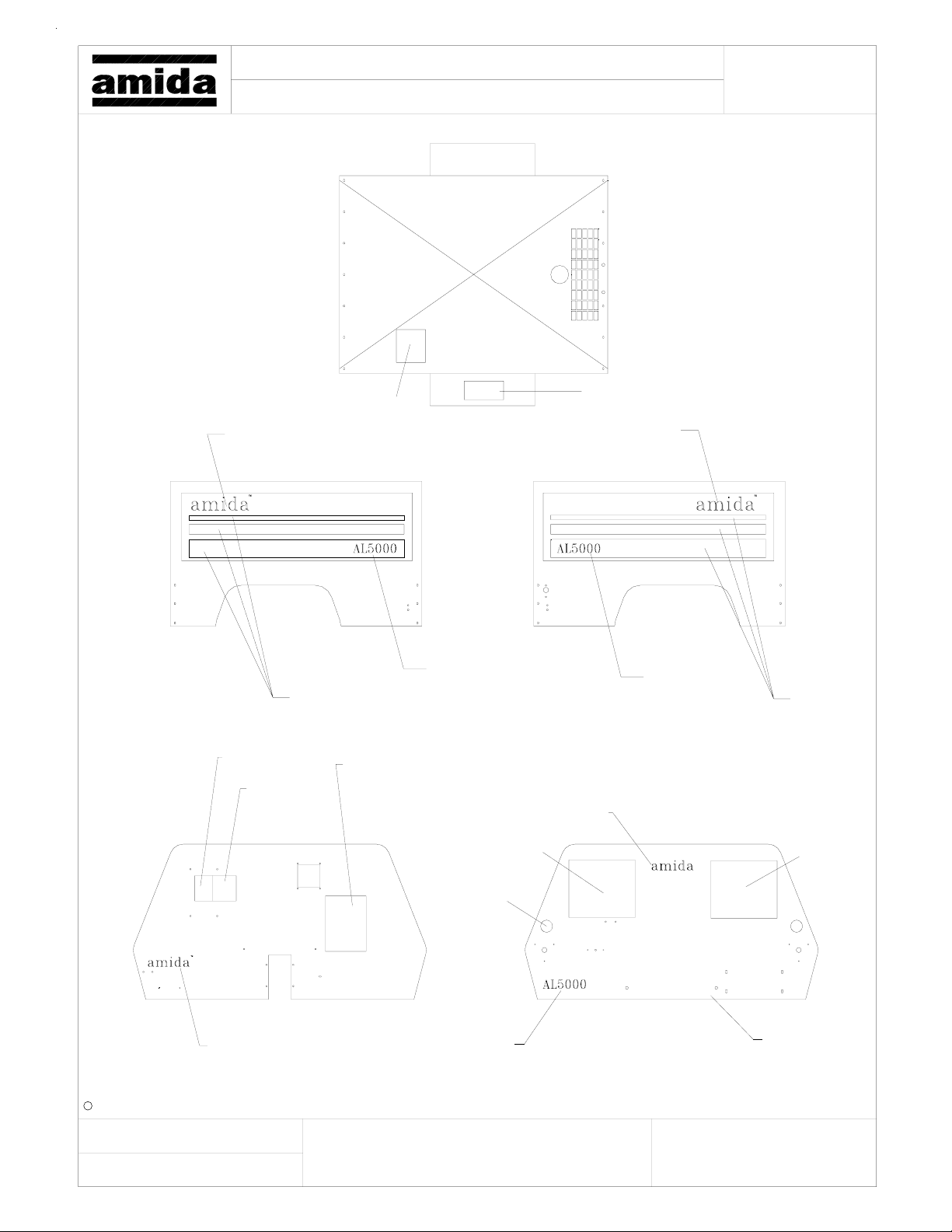
Model:
Title:
853296
AL5000 LIGHT TOWER
Cabinet Dec a ls
Top
850091
Page:
851640
853296
Curb Side
851860
851640
Front
853346
852410
853531
(2) 841710
850092
Road Side
853531
853351
853291
Rear
850093
c Amida Industries, Inc. 1999
Created:
By:
853291
1-26-99
Spectrum
Revised:
www.terex.com
853531
a)
b)
d)
e)
f)c)
Document:
850135
25
Page 26
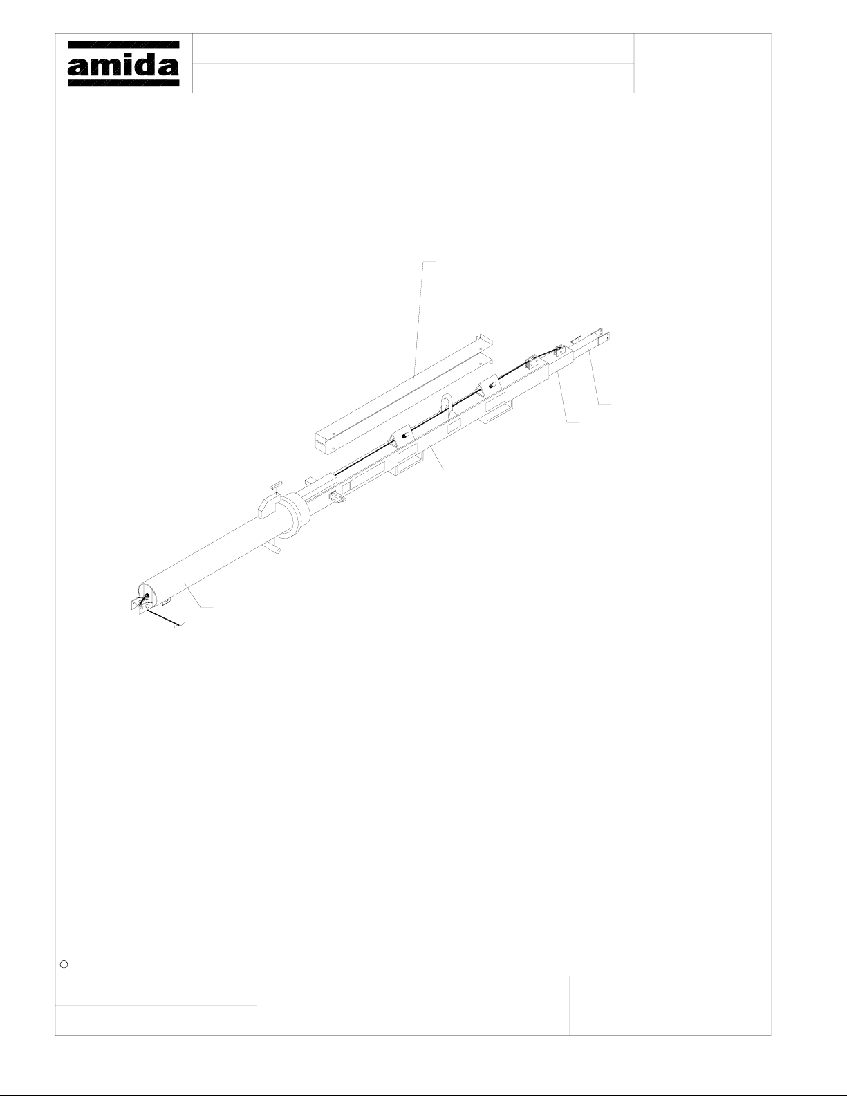
Model:
Title:
AL5000 LIGHT TOWER
Tower Assy.
113080, Coil Cord Sleeve
Page:
See 2" Section
See 3" Section
See 6" Round Tube
See 4" Section
c Amida Industries, Inc. 1999
Created:
By:
2-2-99
Spectrum
Revised:
a)
b)
d)
e)
f)c)
Document:
26
Page 27
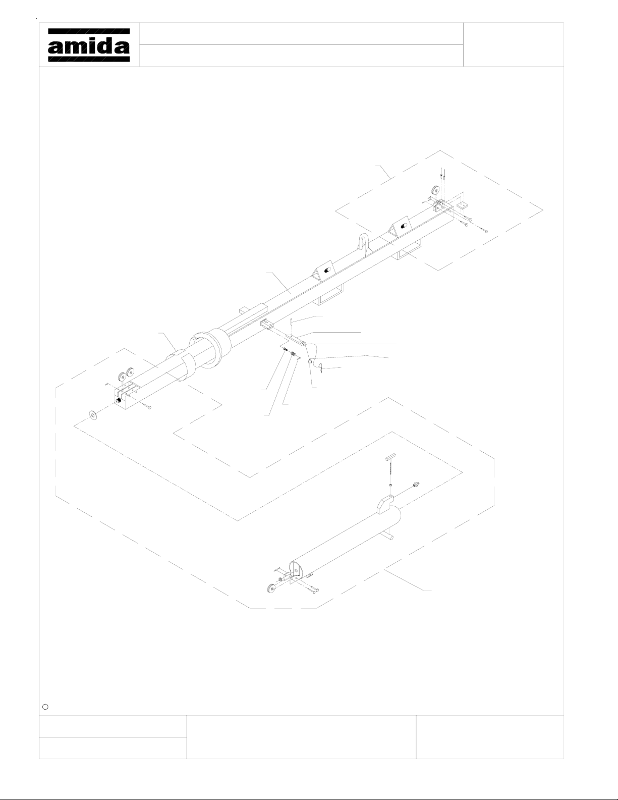
Model: Page:
Title:
AL5000 LIGHT TOWER
4" Tower Section
See Sheave & Shim Assembly
124540, 4" Tower Section
990660, Roll Pin
177810
Shim
120220, Lock Pin
790510, 1/16" Cable
(3) 790520, Cable Sleeve
990760, "R" Pin
980340
Screw
790710
Spring
120640, Pin
990650
Cotter Pin
See 6" Round Tube
By:
c Amida Industries, Inc. 1999
2-2-99
Spectrum
a)
b)
c) f)
d)
e)
Document:Revised:Created:
27
Page 28
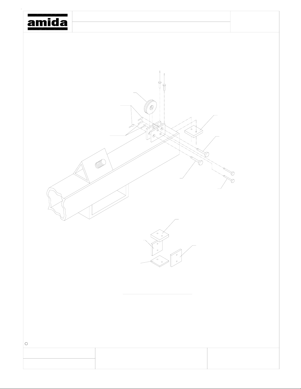
Model:
Title:
AL5000 LIGHT TOWER
4" Tower Sec./Upr. Sheave & Shim Assy.
188760
Sheave
(2) 990650
Cotter Pin
Page:
183285, Shim
See Orientation Below
(2) 994920
Cotter Pin
183286, 5/16" Shim
183288, 3/16" Shim
995780
Clevis Pin
992765
Clevis Pin
(2) 995790
Clevis Pin
183285, 3/8" Shim
177830, 1/4" Shim
c Amida Industries, Inc. 1999
Created:
By:
2-2-99
Spectrum
Revised:
Orientation of Shims Inside Tube
a)
b)
d)
e)
f)c)
28
Document:
Page 29
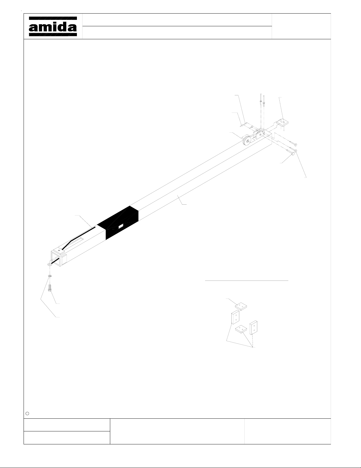
Model:
Title:
AL5000 LIGHT TOWER
3" Tower Section
Page:
192904
Cable
(2) 994920
Cotter Pin
990650
Cotter Pin
188760
Sheave
124550
3" Tower Section
185290, Shim
See Orientation
Below
992765
Clevis Pin
(2) 995790
Clevis Pin
c Amida Industries, Inc. 1999
Created:
By:
996230 3/8" Screw
990470, Lock Washer
2-2-99
Spectrum
Revised:
Orientation of Shims Inside Tube
185290, 3/8" Shim
(3) 177820, 5/16" Shim
a)
b)
d)
e)
f)c)
Document:
29
Page 30
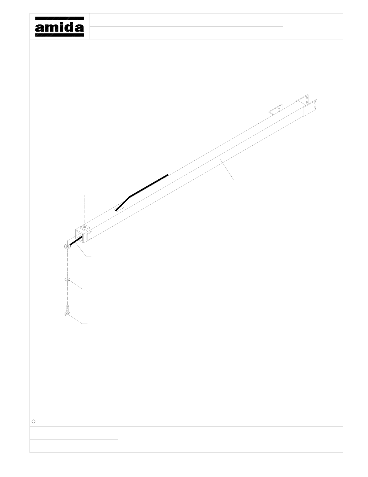
Model: Page:
Title:
AL5000 LIGHT TOWER
2" Section
124560, 2" Tower Section
By:
190570, Cable
990470, Lock Washer
996230, 3/8" Bolt
c Amida Industries, Inc. 1999
2-2-99
Spectrum
a)
b)
c) f)
d)
e)
Document:Revised:Created:
30
Page 31
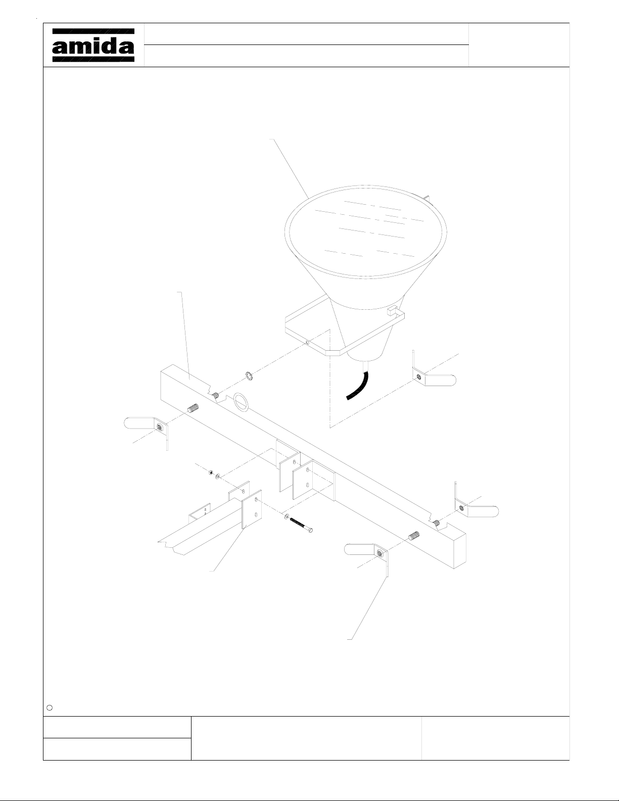
Model:
Title:
(4) See Fixture Assembly
113040, Cross Arm
AL5000 LIGHT TOWER
Tower Crossarm / Fixture
Page:
c Amida Industries, Inc. 1999
Created:
By:
Cross Arm Mounting Plate
(4) 123080, Fixture Mounting Wing Nut
2-2-99
Revised:
Spectrum
a)
b)
d)
e)
f)c)
Document:
31
Page 32
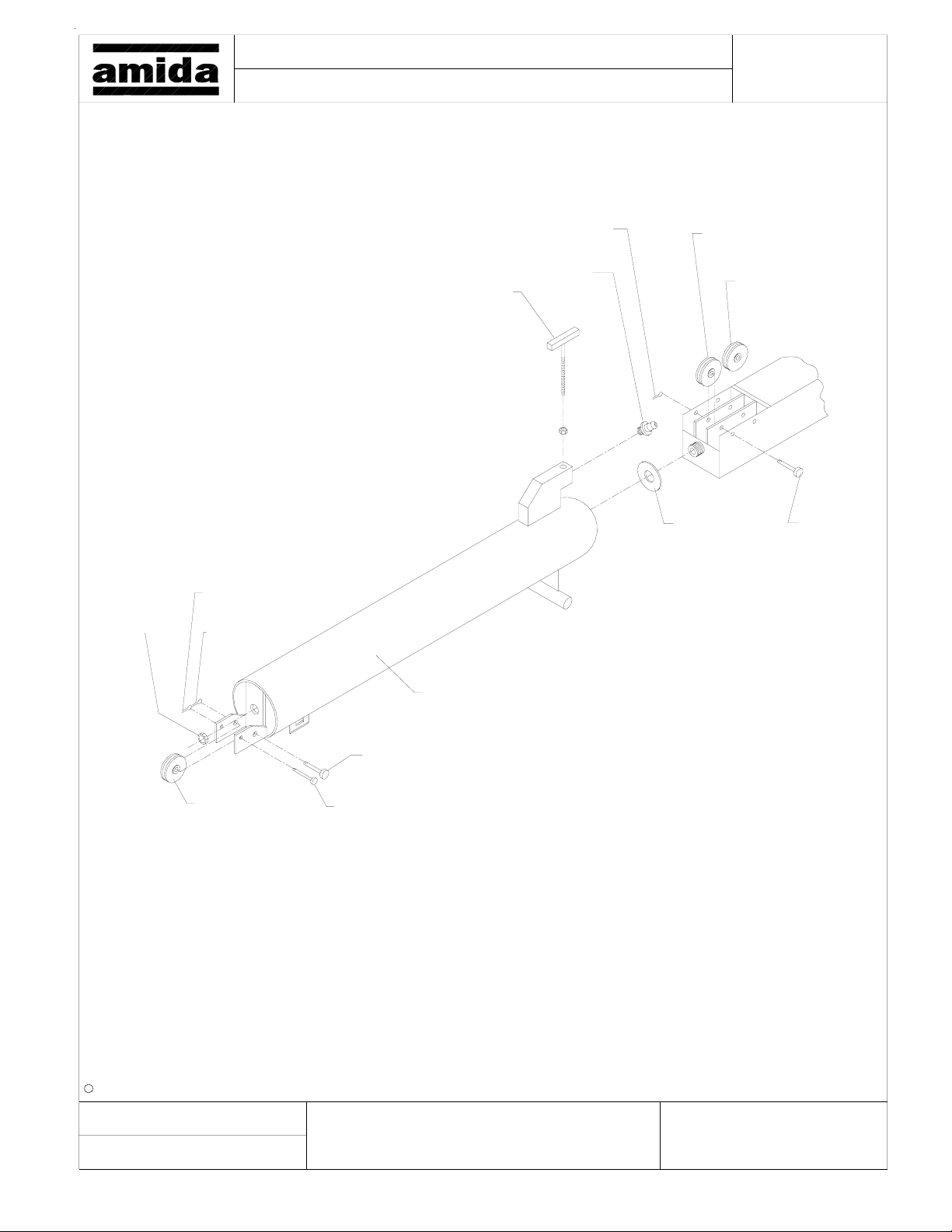
Model: Page:
Title:
AL5000 LIGHT TOWER
6" Round Tube
990620
Lock Nut
994920
Cotter Pin
990650
Cotter Pin
990610
Tee Bolt
990650
Cotter Pin
794550
Grease Fit.
188770
Sheave
179850
Bushing
188760
Sheave
(2) 992765
Clevis Pin
By:
124530
6" Round Tube
992765
Clevis Pin
188760
Sheave
c Amida Industries, Inc. 1999
2-2-99
Spectrum
995790
Clevis Pin
a)
b)
c) f)
d)
e)
Document:Revised:Created:
32
Page 33
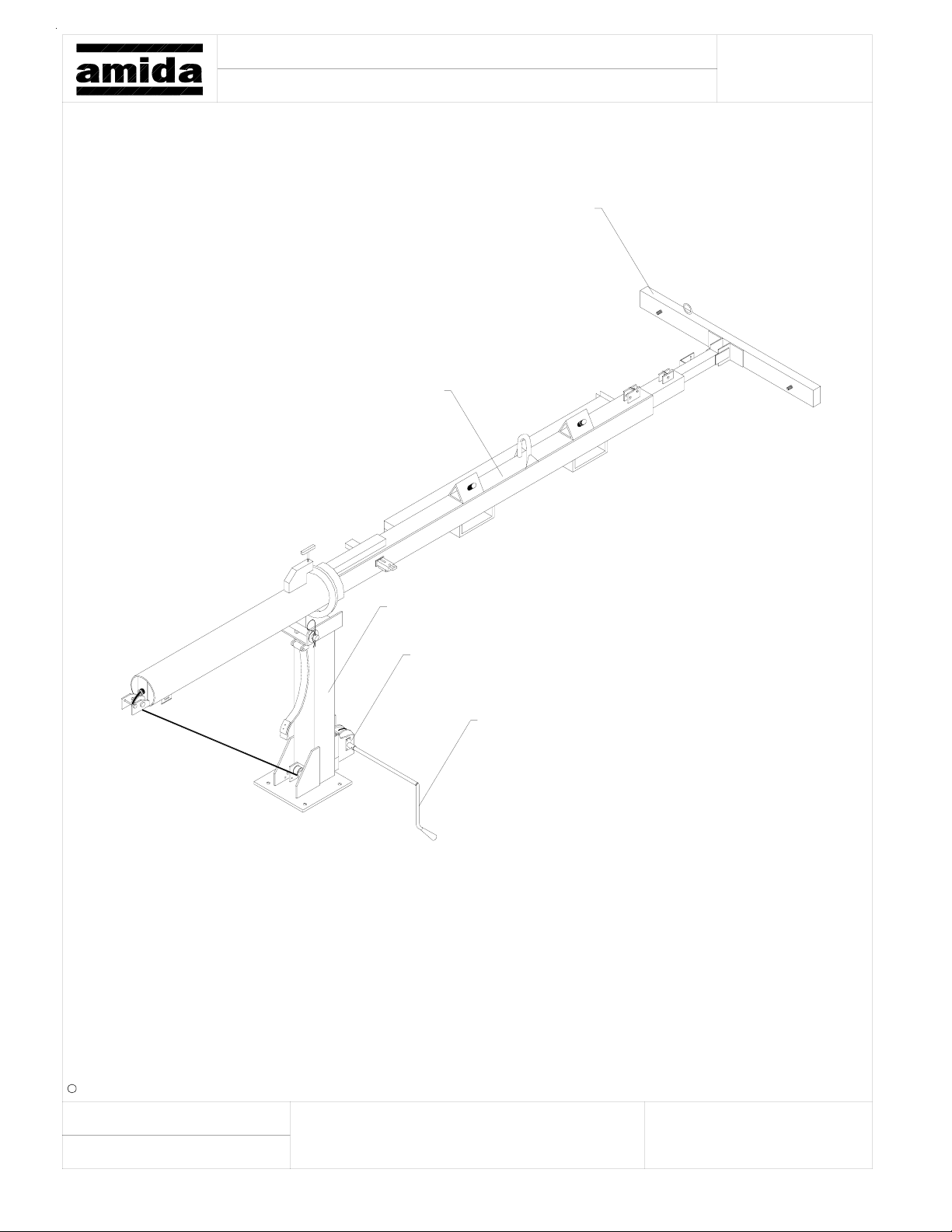
Model:
Title:
AL5000 LIGHT TOWER
Tower w/ Base Assy.
116220, Tower Assy. w/ Cables
Page:
113040, Crossarm
116170, Tower Base
740050, Winch 1500#
124480, Winch Handle
c Amida Industries, Inc. 1999
Created:
By:
2-2-99
Spectrum
Revised:
a)
b)
d)
e)
f)c)
Document:
33
Page 34
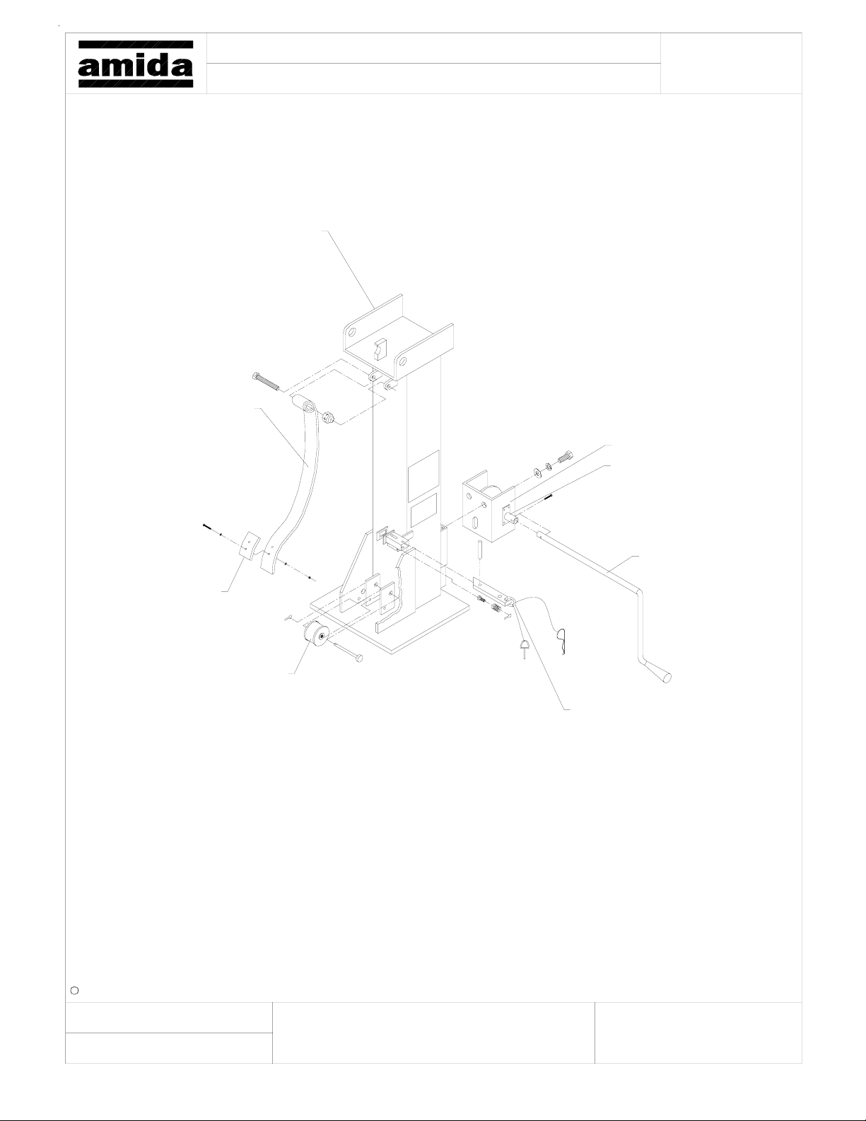
Model:
Title:
124490, Tower Base
193750, Kick-Out Spring
AL5000 LIGHT TOWER
Tower Base Assy.
Page:
740050, Manual Winch
111680 Winch Socket
186360, Bumper Pad
184510, Spool Sheave
124480, Winch Handle
120220, Pin Slide Lock
c Amida Industries, Inc. 1999
Created:
By:
2-2-99
Spectrum
Revised:
a)
b)
d)
e)
f)c)
Document:
34
Page 35
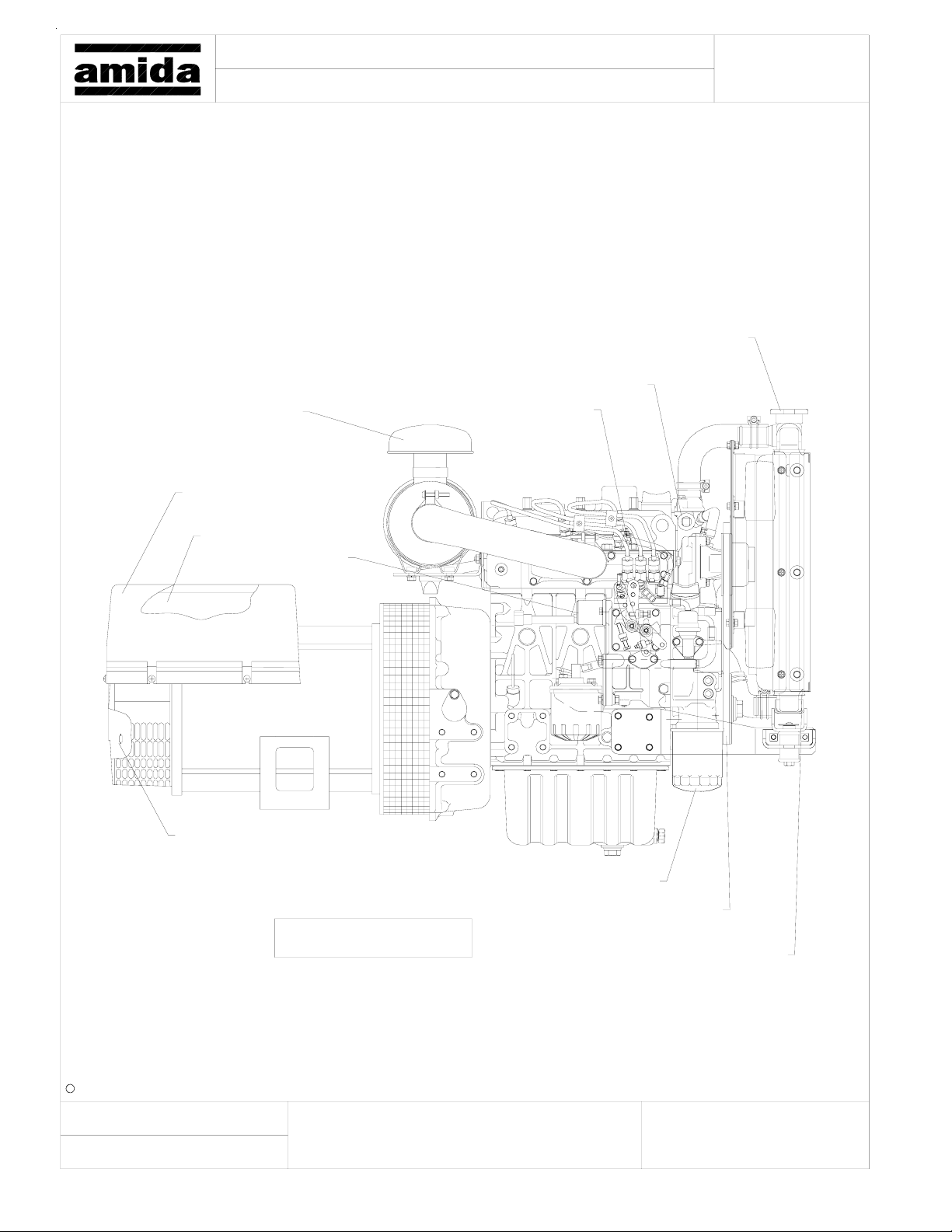
Model: Page:
Title:
866010, Air Cleaner
630960, Generator
AL5000 LIGHT TOWER
Genset, Kub-D1105/L-S 8KW
866120, Radiator Cap
741140, Temp. Sender
732200, Engine
109350, Capacitor
866030, Soleniod
866040, Gasket
836857, Diode
865223, Electric Fuel Pump
Mounted to Trailer Frame
866050, Oil Filter
866080, V-Belt
866110, Radiator
By:
c Amida Industries, Inc. 1997
9-5-97
Spectrum
a)
b)
c) f)
d)
e)
Document:Revised:Created:
35
Page 36
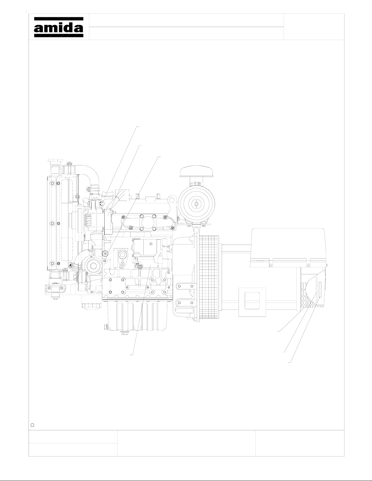
Model:
Title:
AL5000 LIGHT TOWER
Genset, Kub-D1105/L-S 8KW
732200, Engine
866090, Alternator
839190, Low Oil Press. Sensor
Page:
c Amida Industries, Inc. 1997
Created:
By:
9-5-97
Spectrum
866100, Starter
Revised:
836835, End-Kit With Bearing
836830, O-Ring
836828, Rear Bearing
a)
b)
d)
e)
f)c)
Document:
36
Page 37
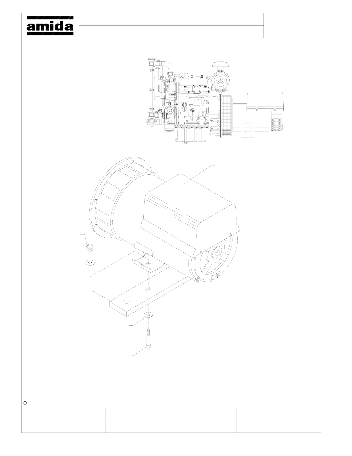
Model:
Title:
AL5000 LIGHT TOWER
Generator Mounting Bar
Page:
630960, Generator
(2) 990200
Lock Nut
189335, Generator
Mounting Bar
(4) 990210, Flat Washer
(2) 990820, Bolt
c Amida Industries, Inc. 1997
Created:
By:
9-5-97
Spectrum
Revised:
a)
b)
d)
e)
f)c)
Document:
37
Page 38
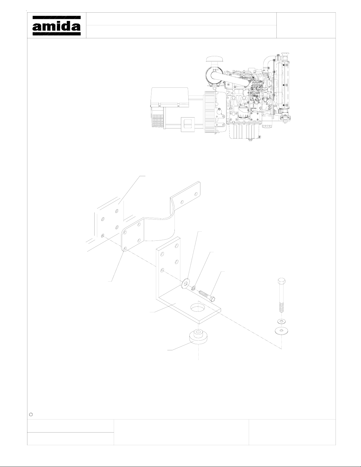
Model: Page:
Title:
Right Side Radiator/Engine Mtg. Bracket
AL5000 LIGHT TOWER
Engine Block
Radiator Mounting Bracket
189290, Engine Mounting Bracket
740920, Vibration Mount Assy.
(4) R980175, Flat Washer
(4) 994830, Lockwasher
(4) 995110, Screw
By:
c Amida Industries, Inc. 1997
9-5-97
Spectrum
a)
b)
c) f)
38
d)
e)
Document:Revised:Created:
Page 39
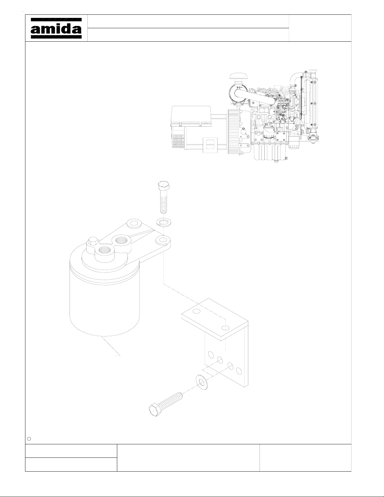
Model:
Title:
AL5000 LIGHT TOWER
Fuel Filter
Page:
839200, Kubota Fuel Filter
c Amida Industries, Inc. 1997
Created:
By:
9-5-97
Spectrum
Revised:
a)
b)
d)
e)
f)c)
Document:
39
Page 40
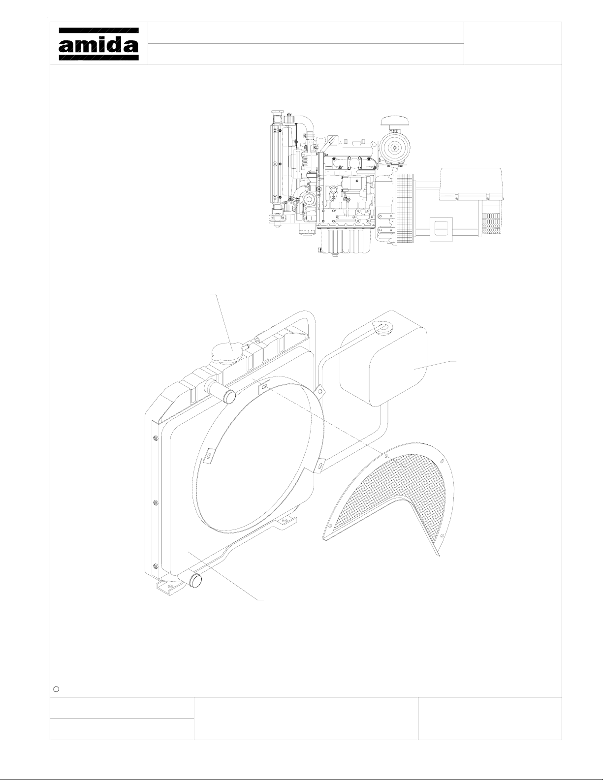
Model: Page:
Title:
866120, Radiator Cap
AL5000 LIGHT TOWER
Radiator/Overflow Tank
866110, Radiator
865307, Overflow Tank
By:
c Amida Industries, Inc. 1997
9-5-97
Spectrum
a)
b)
c) f)
d)
e)
Document:Revised:Created:
40
Page 41
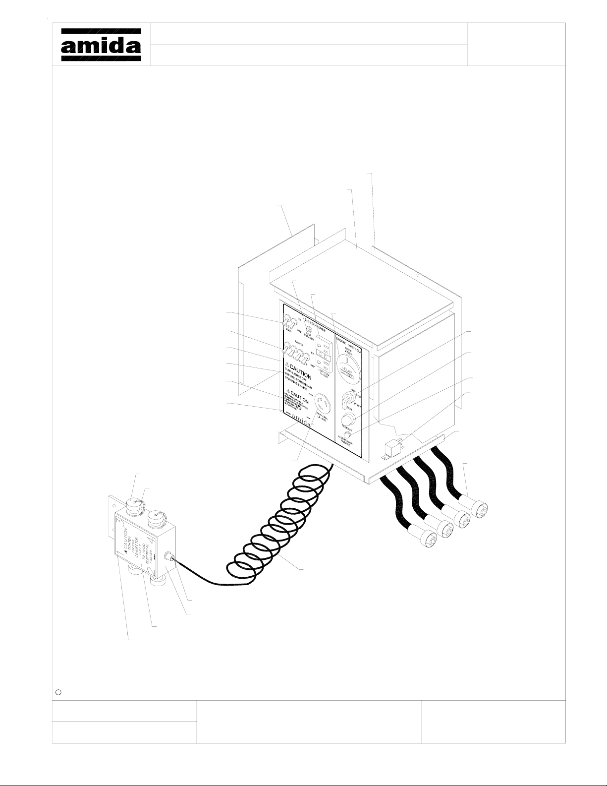
Model:
Title:
185390, Control Box Side
683680, Breaker 2P-30A
(4) 683870, Breaker 1P-15A
189170, Control Box Face
851790, Decal
853190, Decal
853280, Decal
AL5000 LIGHT TOWER
Electrical AC/DC, 4 MH/HPS
186730, Control Box Rear
186801, Control Box Top
683970, Mini-Breaker
684640, Duplex Receptacle
W/ GFI
260360, Hour Meter
Page:
684380, Switch
R660010, Push-
Button Switch
682715, Light
R661490, Relay
c Amida Industries, Inc. 1999
Created:
By:
663880 Cap For Receptacle
680190, Box Cover W/ Gasket
1-26-99
Spectrum
684450, T-Lock Receptacle
663870, Connector 3P Female
680080, Strain Relief
121620, Box W/ Mount Bar
852800, Decal
Revised:
a)
b)
660287, Coil Cord
d)
e)
f)c)
186781, Control
Box Bottom
663890, Female
Cord Set
Document:
41
Page 42
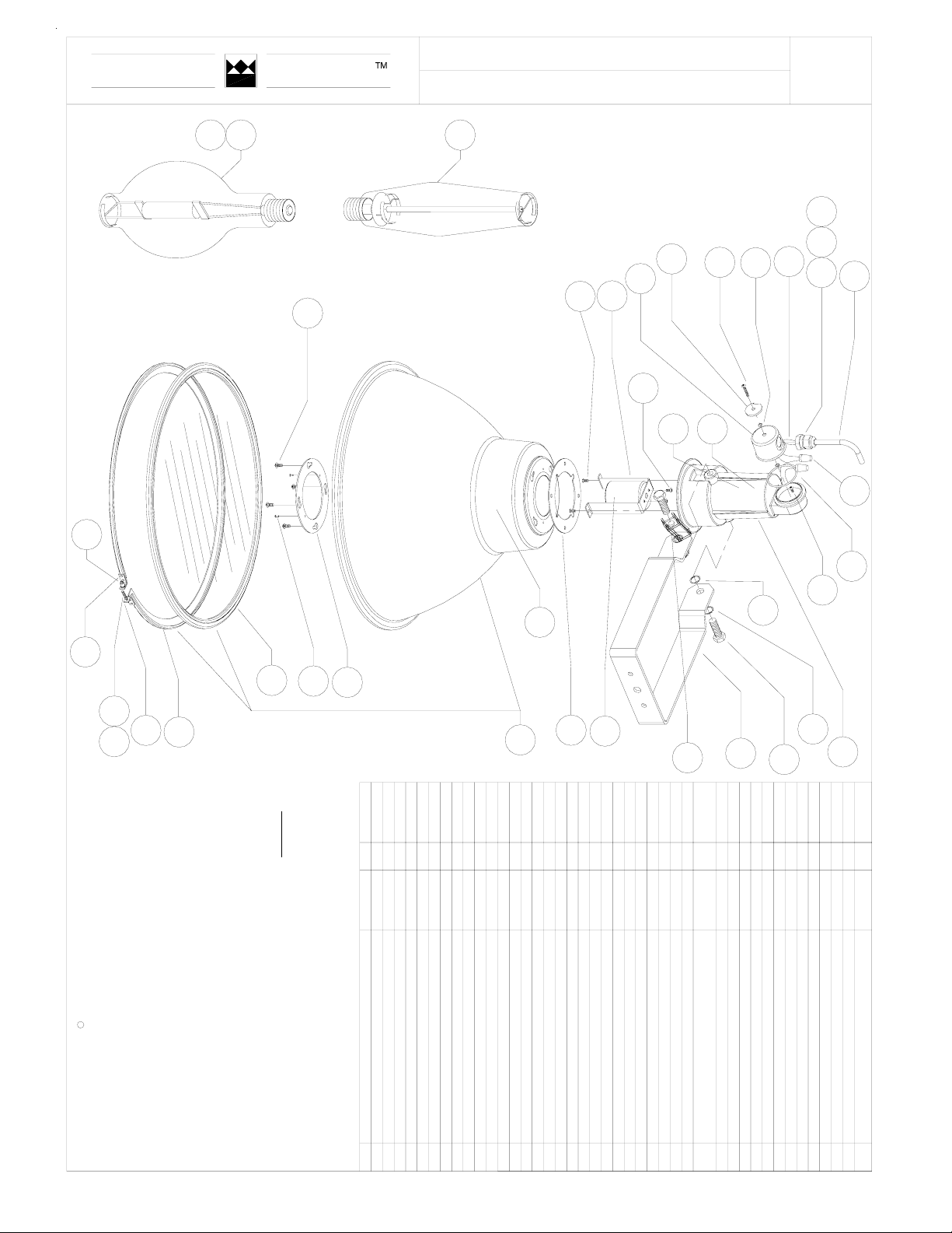
TEREX
30
amida
26
12
112605-STANDARD LIGHT TOWER
MH/ MV/ HPS LIGHT FIXTURE
28
34
1
3
5
23
40
2
38
21
37
Page:
3132
18
20
29
27
30
1936
28
15
13
NOTE:
FOR COMPLETE ASSEMBLY
ORDER PART# 112605
25
11
833585
995970
791.1137
4110624000
LBL FIXTURE CSA - NRTL/C
WASHER 1/2 EXTER. TOOTH LOCK SS
833584
404142
791.2395
LBL 105C SUPPLY COND.
833583
38
791.2397
LBL WET LOCATION/EXTERIOR
833582
37
690.0121
FIBERGLASS SLEEVE 2-1/2"
833581
36
4110953000
FIBER WASHER
833580
34
635.1110
WASHER 1/4 X 1-1/4" OD
680020
32
634.0042
LOCKNUT 1/2
683950
31
690.0446
SEAL RING .755" ID - EPDM
160130
LAMP, 1000 WATT MERCURY VAPOR (OPT.)
9
160140
833579
282930
4100109000
MARRETS 150°C 2 WIRE NUT #16
LAMP, 1000 WATT HIGH PRESSURE SODIUM (OPT.)
NUTSERT 8-32 X Ø1/4" X 13/32 " LENGHT
41
833578
27
634.8005
160071
LAMP, 1000 WATT METAL HALIDE
10
990675
991650
242526
4104021000
4110310000
SPLIT WASHER 1/2 SS
RIVETS Ø1/8" ALUM. 3/16" LENGHT
4
833577
833576
23
4107742000
4106784000
SCRW 6-32"TT" X 3/8 PH PH ZN
SCREW 8-32 x 5/8" FH PH MS ZC
833575
245.0121
O-RING 0.206" ID x Ø0.103 SILICON
202122
84287
CORD #16-3 SIOW 105°C + 2 TERM. RING
663850
833574
19
630.8928
SCREW 8-32 X 1 HH SL MS SS
682470
690.0447
STRAIN RELIEF #2521 T&B
410.1032
HANDLE FOR 1/2-13 BOLT (DWG) (OPTIONAL)
833573
833572
161718
245.0119
O-RING 1.925" ID x Ø0.103" SILICON
833543
15
410.2027
CLAMP BAND Ø19.5" ALUMINUM
17
833524
13
555.0079
COMBINATION
245.0124
VULCANIZED GASKET SILICONE - 1/8" LENS
833571
12
70463
SCREW 10-24 x 5/8 HW SL TT
833570
410.1024
REINFORCING RING (T&B - B60198)
16
22
42
24
833564
833565
4605079000
4106781000
SOCKET MOGUL BASE W/ WIRES
SCREW 8-32 x 3/8" PH PH TT ZC
833563
410.1023
SOCKET BRACKET (T&B 057-05-80643)
7
833562
630.1045
SCREW 1/4-20 x 2" PH SS
833561
1234567891011
410.0003
ALUM. CONNECTION BOX
TEREX PART#
#
POWERLITE#
DESCRIPTION
6
8
833567
990810
833547
833569
833566
310.0056
4103054000
410.5021
245.0120
GASKET HIF (T&B - B61178)
410.1021
HOUSING ALUM. CST. FOR GENERATOR
BOLT 1/2-13 x 1-1/2" HH MS SS
REFLECTOR 18" ALUM. PEENED W / LENS & BAND
TRUNNION FOR GENERATOR
c TEREX Light Construction, 2000
211
1
1
1
111.52
1
1
1
222
11111
2
1
1
4
111
1
1
1
1
2
2
QTY.
111
42
Page 43
Model:
Title:
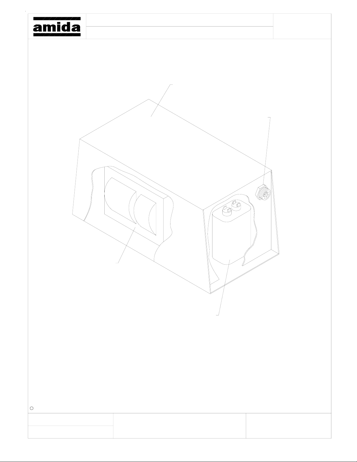
AL5000 LIGHT TOWER
Ballast
114355, Ballast Box MH
114895, Ballast Box HPS
663860, 5 Pin Connector
Page:
c Amida Industries, Inc. 1999
Created:
By:
160030, Ballast MH
160040, Balast HPS
2-2-99
Spectrum
Revised:
160032, Capacitor MH
160042, Capacitor HPS
a)
b)
d)
e)
f)c)
Document:
43
Page 44
Model:
Title:
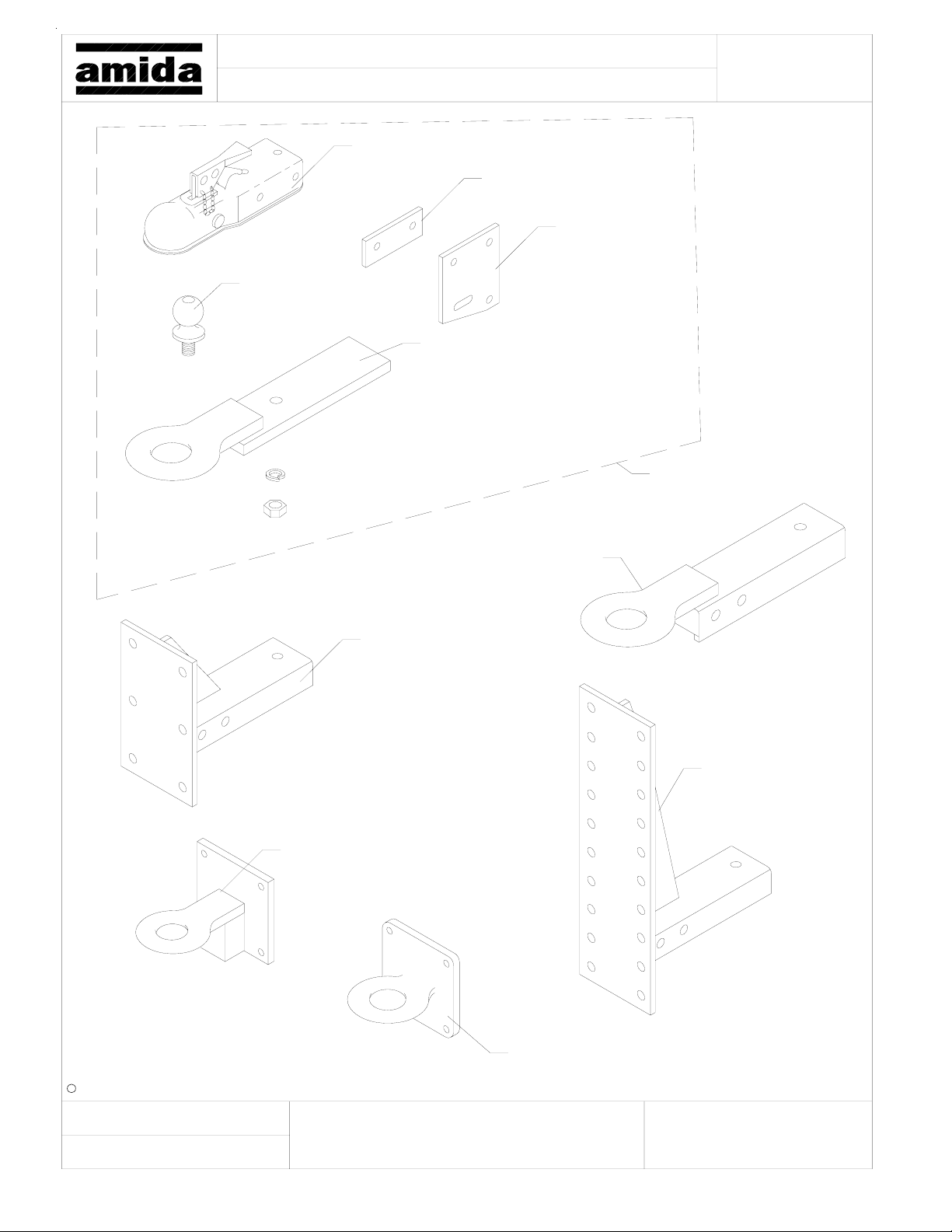
840470, Ball, 2"
SAE-2
AL5000 LIGHT TOWER
Trailer Hitches
840120, Coupler, 2"
176336, Spacer
121572, Combo Hitch Ring
16" Long
Page:
176335, Plate
940000, Kit, Combo
Hitch
213770, Ring Hitch
124450, Hitch, 24" Height
211410, Ring Hitch for Adj Height
2-1/2" I.D.
221580, Hitch,
Adj. Height
By:
841200, Hitch, Pintle Ring, 3" I.D.
c Amida Industries, Inc. 1999
2-2-99
Spectrum
Revised:Created:
a)
b)
c) f)
d)
e)
Document:
44
Page 45
001
004
003
OPTION #
DWG/ITEM #
001
002
003
004
DRAWN BY DATE
0LTX0690
160992
113583
160993
663780
BLB
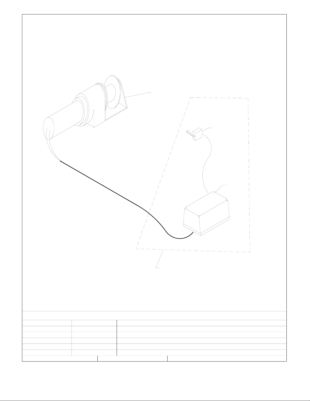
WINCH, ELEC. 12V DC (STD) AL4000/AL5000
PART #
002
DESCRIPTION
WINCH 12V
WINCH SWITCH W/ SOLE NO ID ASS'Y
WINCH SOLENOID
WINCH TOGGLE SWITCH
2/8/96
DRAWING NO.
45
8149
Page 46
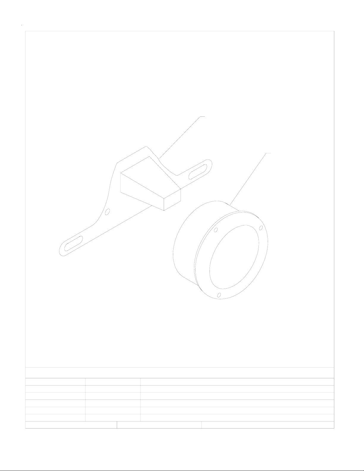
002
001
OPTION #
8126 - 001
8126 - 002
0LTX0080 STOP TAIL & TURN LIGHT AND LICENSE TAG LIGHT
DESCRIPTION
DRAWING NO.
8126
CNM
PART #DWG/ITEM #
663510
663520
STOP TAIL & TURN LIGHT
LICENSE TAG LIGHT W/BRACKET
DATEDRAWN BY
4/4/91
46
Page 47
#REQ
"B"
NONE
2985A
DWG.#
2985A
BORDER
SCALE
DWG.#
DESCRIPTION
CHANGE
WD2985
PART#
PART#
ITEM#
590 HUEY Rd, ROCK HILL, S.C.
Ph. (803) 324-3011 FAX 366-1101
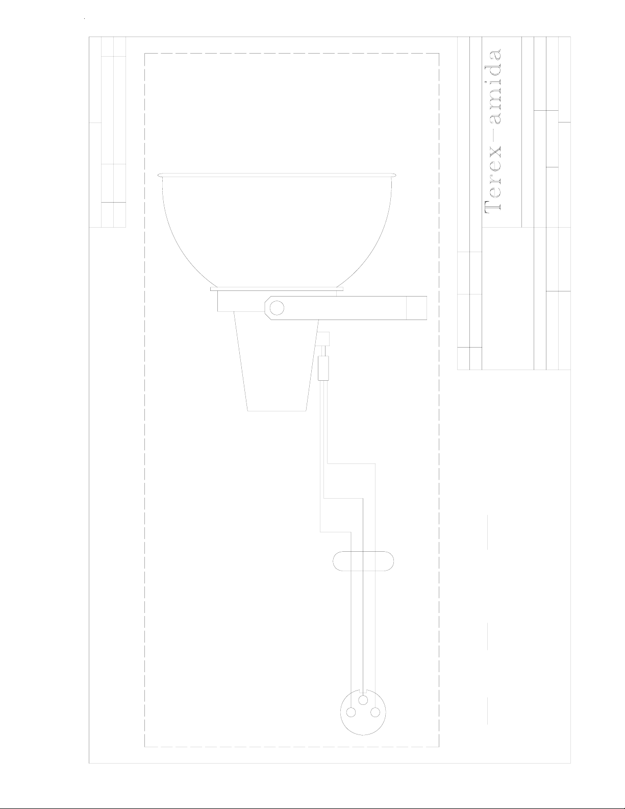
WIRING DIAGRAM, MH OR HPS FIXTURE
WD2985
DR BY
W/JOY CONNECTOR
PART#
ADDED EUROPEAN (CE) WIRING DATA
ECO #
.XXXX=±.005
Degrees ±1/2°
Fractions ±1/16
DATE
3/15/00
A
REV.
TOLERANCES UNLESS OTHERWISE SPECIFIED:
REMOVE ALL BURRS & SHARP EDGES
Decimals .XX=±.030 .XXX=±.010
MATL.
4/30/91
MAT P/N
PLOT 4/30/91DATE
47
COMMON FROM BALLAST
HOT FROM BALLAST (LIVE)
CIRCUIT
GROUND (EARTH)
14/3
LIGHT BLUE
GREEN W/YELLOW
BROWN
CODE
EUROPEAN
DOMESTIC
COLOR
COLOR
CODE
GREEN
BLACK
WHITE
WHITE (BLUE)
GREEN (GRN/YEL)
NOTE:
PIN CONFIGURATION IS THE SAME
FOR TUNGSTEN HALOG E N FIXTURES
BLACK (BROWN)
Page 48
#REQ
"B"
2986
DWG.#
DESCRIPTION
2986
BORDER
SCALE: NONE
DWG.#
CHANGE
PART#
WD2986
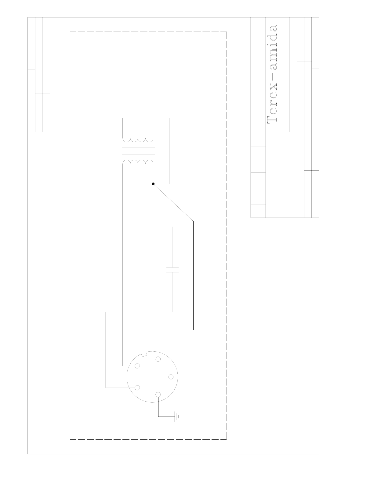
TRANSFORMER
(1000W METAL HALIDE BALLAST)
ITEM#
PART#
590 HUEY Rd, ROCK HILL, S.C.
Ph. (803) 324-3011 FAX 366-1101
WIRING DIAGRAM - 1000MH BALLAST
W / JOY CONNECTOR
WD2986
DR BY: CNM
PART#
CAP
USAGE
COM
ECO #
.XXXX=±.005
Degrees ±1/2°
Fractions ±1/16
DATE
MATL
Decimals .XX=±.030 .XXX=±.010
REV.
TOLERANCES UNLESS OTHERWISE SPECIFIED:
REMOVE ALL BURRS & SHARP EDGES
PLOT: 4/30/91 DATE: 4/30/91
MAT P/N
MATL.
24 MF
480V
C1
LAMP COMMON
INPUT COMMON
BLACK 120V
WHITE
INPUT 120V
RED
ORANGE
COLOR CIRCUIT
RED LAMP HOT
ORANGE
WHITE
BLACK
GREEN GROUND
5-POLE
RECEPTACLE
GRN
48
Page 49

#REQ
"A"
WD2987
2987
DWG.#
PART#
2987
BORDER
SCALE: NONE
DWG.#
DESCRIPTION
TRANSFORMER
CHANGE
PART#
WD2987
590 HUEY Rd, ROCK HILL, S.C.
ITEM#
Ph. (803) 324-3011 FAX 366-1101
WIRING DIAGRAM - 1000HPS BALLAST
W / JOY CONNECTOR
DR BY:CNM
PART#
(1000W HIGH PRESSURE SODIUM BALLAST)
26uF
C1
450V
ECO #
DATE: 4/30/91
USAGE
IGNITOR
X2 X3
X1
BLACK
.XXXX=±.005
Fractions ±1/ 16
Degrees ±1/2°
DATE
MATL
Decimals .XX=±.030 .XXX=±.010
INPUT COMMON
REMOVE ALL BURRS & SHARP EDGES
LAMP COMMON
LAMP HOT
PLOT: 4/30/91
MAT P/N
MATL.
GROUND
TOLERANCES UNLESS OTHERWISE SPECIFIED:
REV.
WHITE
RED
INPUT 120V
5-POLE
RECEPTACLE
GREEN
COLOR CIRCUIT
GREEN
ORANGE
RED
WHITE
BLACK
ORANGE
49
Page 50
#REQ
"B"
NONE
2763B
DWG.#
DESCRIPTION
2763B
BORDER
SCALE
DWG.#
CHANGE
PART#
WD2763
ITEM#
PART#
TO "ACC"
TERMINAL ON
START SWITCH
RED
*
DC
12V
OUTPUT
BATTERY
BATTERY CHARGER (OPTIONAL*)
CHARGER
AC
* LISTER TR/TS UNITS ONLY
INPUT
120V
#10 BLK
120V-15AMP
GFI PROTECTED
RECEPTACLE BOX AT TOP OF TOWER
RECEPTACLES
TYP. 4
3
A
C
B
A
C
B
1
240V
30 AMP
RECEPTACLE
#10 RED
#14 BLK
3 POLE RECEPTACLE
4
#14 YEL
#14 GREEN
CORD
RETRACTABLE
7-CONDUCTOR
ORN
BLUE
YEL
GRN
RED
WHITE
ECO #
DATE
REV.
#14 YEL
#14 GREEN
#14 RED
B
CD
A
E
#14 RED
B
A
DC
E
#14 RED
#14 YEL
B
A
DC
E
2
#14 BLACK
BALLAST
#14 GREEN
3
BALLAST
#14 YEL
#14 GREEN
#14 RED
B
A
DC
E
4
BALLAST
A
C
B
BLK
A
C
B
2
TYP.4
5-POLE
RECEPTACLE
20 AMP
#12 RED
1
BALLAST
590 HUEY Rd, ROCK HILL, S.C.
Ph. (803) 324-3011 FAX 366-1101
.XXXX=±.005
Degrees ±1/2°
Fractions ±1/16
Decimals .XX=±.030 .XXX=±.010
TOLERANCES UNLESS OTHERWISE SPECIFIED:
GMB
DR BY
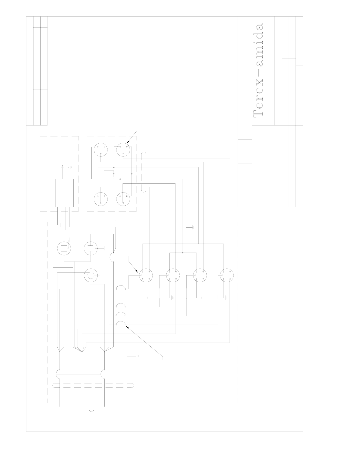
WD-AC CONTROL BOX, 4MH/HPS
AL4/AL5/LT5/SL4
USAGE
REMOVE ALL BURRS & SHARP EDGES
MAT P/N
MATL.
WD2763
PART#
DATE 7/9/93
7/9/93
PLOT
#14 BLK
FLOODLIGHT CONTROL BOX
#14 BLK
BLACK
MAIN BREAKER 30AMP
BLACK
#14 ORN
WHITE
WHITE
RED
RED
GREEN
POWER CORD FROM GENERATOR
#14 ORN
15 AMP
TYP. 4
(FLOODLIGHT)
#14 BLK
#14 ORN
#14 ORN
50
Page 51
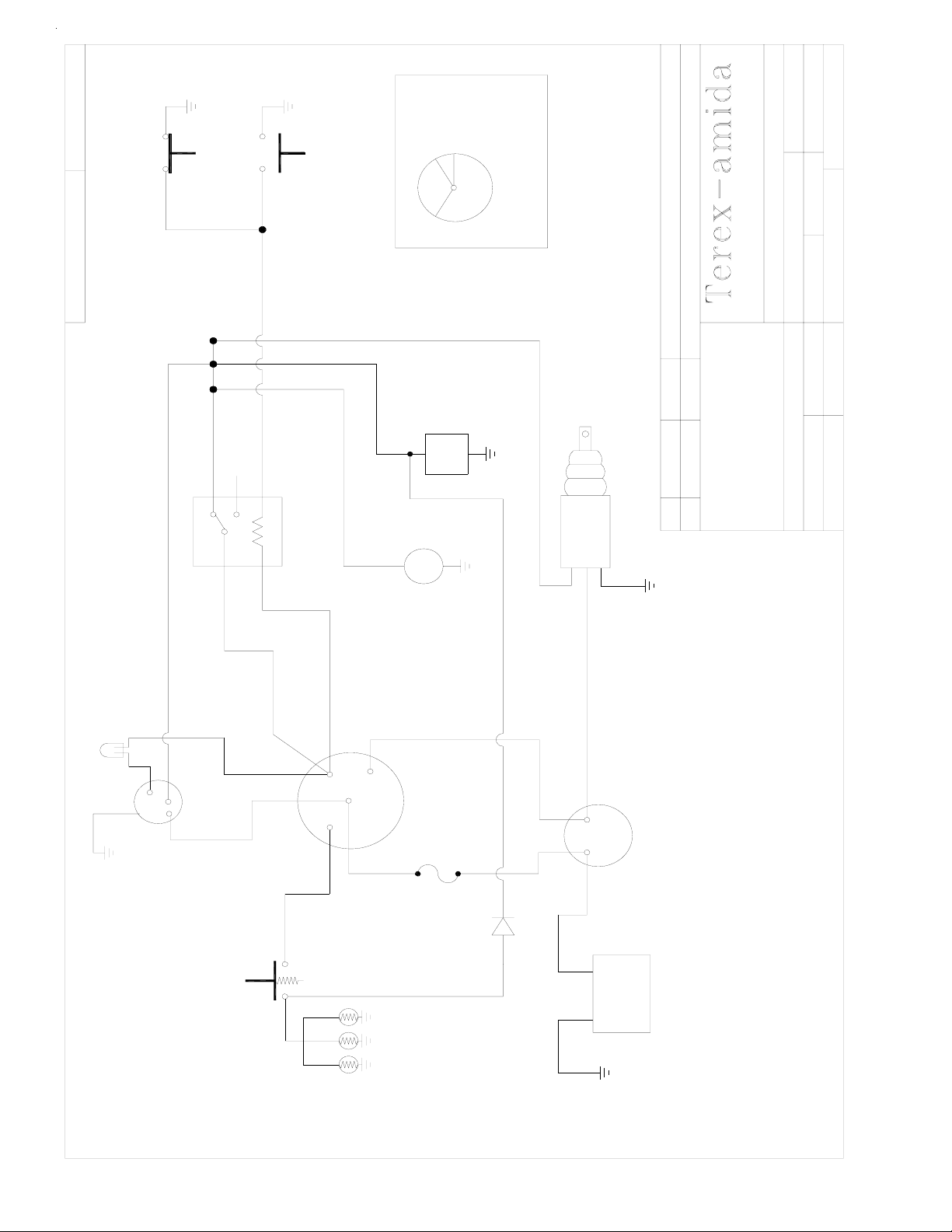
4730E
"B"
N/A
4730E
START
DWG.#
ORANGE
(NC)
LOW OIL
PRESSURE
(NO)
HIGH
COOLANT
TEMPERATURE
IGN & ACC
OFF
BAT
ACC
SWITCH
LEGEND
IGNITION
CHANGE
WD4730
ORANGE
PART#
590 HUEY Rd, ROCK HI L L, S.C.
Ph. (803) 324-3011 FAX 366-1101
ADDED DIODE FOR FUEL PUMP/ PRIME
ECO #
PUMP
RED
(NC)
PURPLE
BROWN
SPST
RELAY 12V
FUEL
FUEL
BROWN
HOLD
PULL
COM
ECO #
SOLENOID
DATE
1/12/01
E
REV.
.XXXX=±.005
Degrees ±1/2°
Fractions ±1/16
Decimals .XX=±.030 .XXX=±.010
TOLERANCES UNLESS OTHERWISE SPECIFI ED:
SCALE
DWG.#
APP BYDR BY JCS
WD4730
WD - DC ENGINE WIRING, KUBOTA
PART#
D905/D1105, AL 4, AL5, TX3
USAGE
REMOVE ALL BURRS & SH AR P E D GES
MATL. BORDER
MAT. P/N
PLOT B 3/23/00 DATE 3/23/00
HOUR
METER
LIGHT
BROWN
GREEN
ALTERNATOR FAILURE
IGBL
RED
ALTERNATOR
PREHEAT
PUSH BUTTON
ORANGE
IGN
ST
BAT
WHITE
RED
ACC
RED
RED
YELLOW
RED
30A
FUSE
RED
GLOW
PLUGS
YELLOW
WHITE
ST
B+
RED
+
-
BLACK
STARTER
BATTERY
12 VOLT
51
Page 52

TEREX Amida Model AL5000
Light Tower – General Specifications
And Routine Maintenance
TEREX Amida model AL5000 series light tower provides mobile; trailer mounted floodlighting for
nighttime maintenance, construction, mining, and emergency work. It consists of a trailer with a diesel
powered 8 kW 60Hz (STD.) generator , and a 30 foot cable actuated tower with four (4) 1000 watt
floodlight fixtures. It is ideally suited for heavy-duty use and is built to meet the following specification:
DIMENSIONS
Overall length, travel position w/fixtures & tongue 183” (4648 mm)
Overall length, tower vertical w/tongue & jacks 128” (3251 mm)
Trailer frame length 74” (1879 mm)
Overall height, floodlighting position 30’ (9.14 m)
Overall height, travel position 69” (1752 mm)
Overall width with fenders 80” (2032 mm)
Overall width with outriggers pulled out 108” (2743 mm)
Trailer frame width 60” (1524 mm)
T ongue length 47” (1193 mm)
Wheel size 15” (381mm)
Axle Rating 3500 lb. (1588 kg)
Tongue weight travel position 220 lb. (99.79 kg)
Total weight no fuel 2425 lb. (1100 kg)
Fuel Capacity 30 gal. (1141)
This section details specifications and maintenance not covered in the operators and trouble-shooting
sections of this manual and the AL5000 specification sheets.
OIL / AIR SERVICE
The engine oil should initially be changed after the first 50 hours of use and then every 200 hours
thereafter. The oil filter should be replaced after every 400 hours of use. The air filter element
should be replaced once every year, or after six cleanings (see manufacturer’ s operation manual
for details).
BRAKE SYSTEM
Electrical or mechanical brakes are not standard equipment on the AL5000. Contact your dealer
or the factory for option information.
52
Page 53
MANUAL WINCH
Maintain a light film of automotive-type grease on the pinion, drum gear, and the O.D. of the
drum bearing at all times. Keep the ratchet pawl pivot, pinion shaft bushings, and pinion threads
lubricated with automotive engine oil at all times. WARNING: Before each use, check the
brake friction discs for wear . If less than 1/16” thick, cracked, or broken, replace IMMEDI-
ATELY. Ratchet pawl should “click” when tower is raised, and not when it is lowered.
WARNING…CAUTION: Always be alert for any fraying of cables, and replace any damaged
cables IMMEDIATELY. Never stand under any object lifted by the winch.
ELECTRIC WINCH
The electric winch is permanently sealed and does not need any periodic lubrication.
WARNING…CAUTION: Always be alert for any fraying of cables, and replace any damaged
cables IMMEDIATELY. Never stand under any object lifted by the winch.
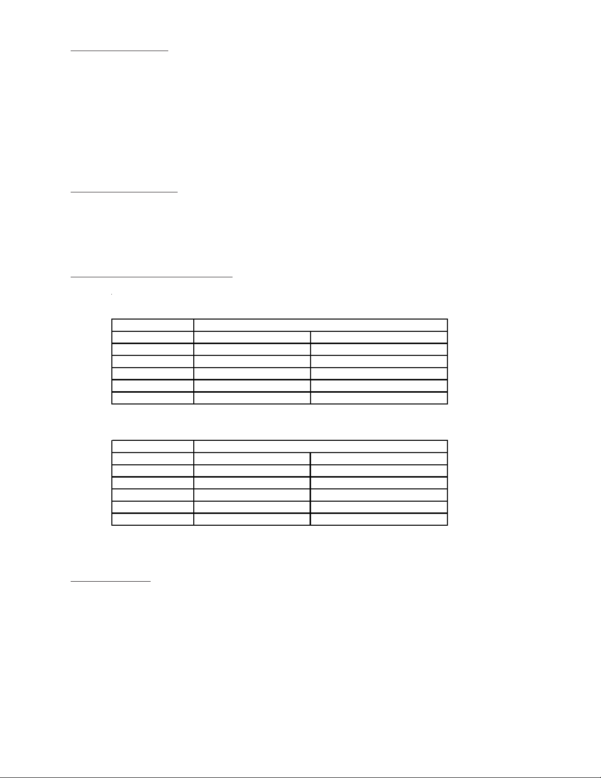
RECETACLE POWER TABLE
METAL HALIDE/ HIGH PRESSURE SODIUM
STATUS RECEPTACLE POWER AVAILABLE 120/240 VAC
LIGHTS ON DUPLEX W/FI 240V- 30A REC.
ALL OFF 15 AMPS* 30 AMPS*
1 OR 3 15 AMPS* 16.6 AMPS
2 OR 4 15 AMPS* 16.6 AMPS
1 AND 3 15 AMPS* 8.3 AMPS
2 AND 4 8.3 AMPS 8.3 AMPS
TUNGSTEN HALOGEN
STATUS RECEPTACLE POWER AVAILABLE 120/240 VAC
LIGHTS ON DUPLEX W/FGI 240V- 30A REC.
ALL OFF 15 AMPS* 30 AMPS*
1 OR 3 15 AMPS* 17 AMPS
2 OR 4 15 AMPS* 17 AMPS
1 AND 3 15 AMPS* 10 AMPS
2 AND 4 15 AMPS* 10 AMPS
• There is more current available than listed. The rating of the duplex receptacle is 15 amps.
NOISE LEVEL
Mean SPL (sound pressure level) hemispherically at 7 meters: 70.80 dBA
Sound Power Level (62.01dBA + 20 log d + 7.8): 95.5 LWA re 1 pW
D = 7 meters using Alpha LPW3 engine and insulated doors.
53
Page 54
MISCELLANEOUS SPECIFICATIONS
The Amida AL5000 light tower is built to NEC standards.
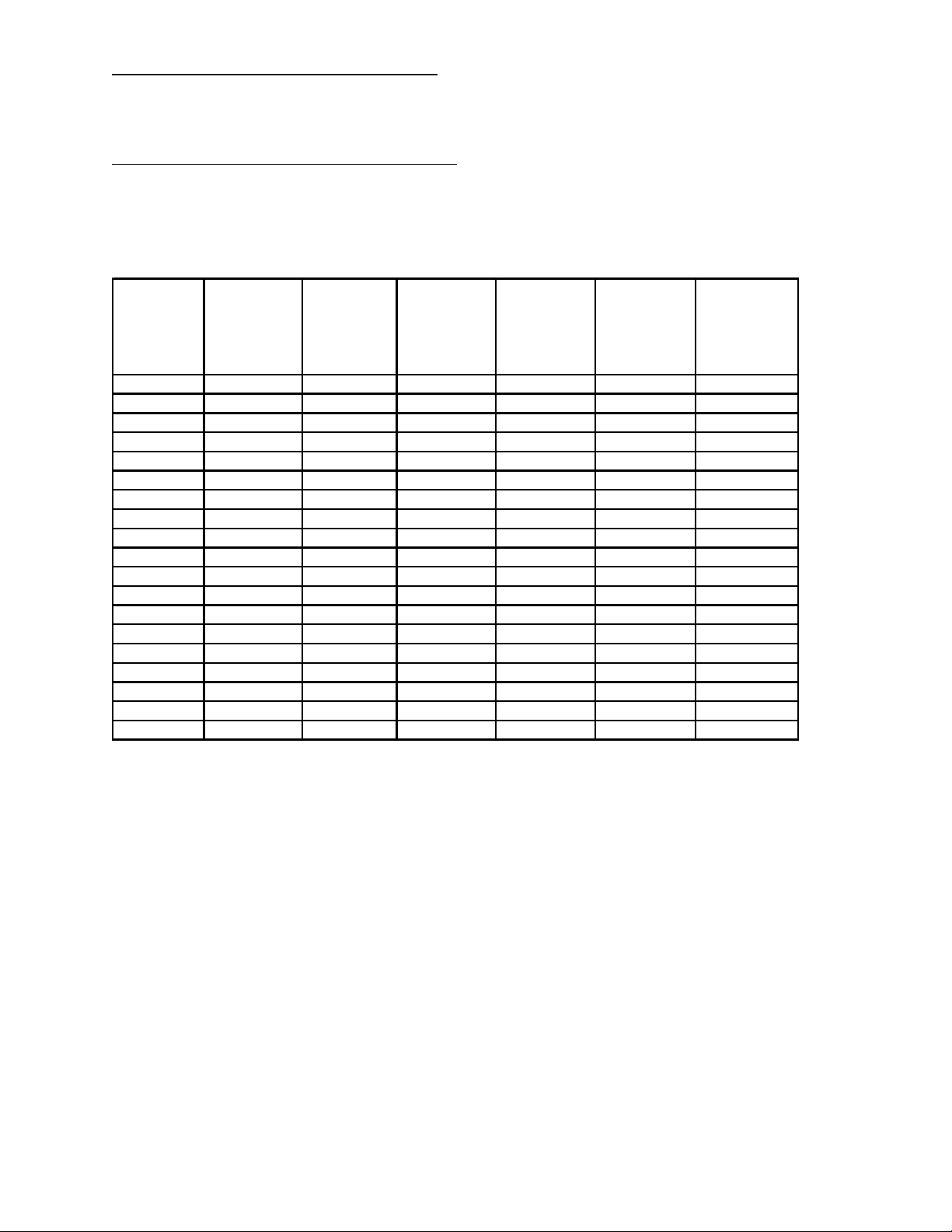
FASTENER TORQUE SPECIFICATIONS
All fasteners should be torqued to the following specifications in lb-ft (lb-in):
FASTENER STAINLESS STAINLESS SAE GRADE SAE GRADE SAE GRADE SAE GRADE
SIZE STEEL* STEEL* 5 PLATED 5 PLATED 8 PLATED 8 PLATED
UNF NYLOK (METRIC NYLOK (METRIC NYLOK
& NUT 8.8) NUT 10.9) NUT
UNC
#6 (10-12) (8.5-10) (14-16)
#8 (20-22) (17-19) (25-28)
#10 (26-32) (22-27) (40-45)
1/4" (75-94) (64-80) 7-9 12-14
5/16" 12-Nov 14-Dec 15-17 23-26
3/8" 20-22 22-24 28-34 45-50
7/16" 31-33 32-35 40-45 70-75
1/2" 43-45 45-50 75-85 70-80 100-110 95-105
9/16" 57-63 60-65 80-100 75-95 145-160 135-150
5/8" 92-104 100-105 130-170 125-165 175-205 165-195
3/4" 128-135 140-150 220-240 205-225 380-420 365-405
4mm (22-26) (19-22) (23-27)
6mm (45-50) (38-43) (72-78)
8mm 12-Nov 9-10 14-16
10mm 18-20 15-17 45-50 40-45 70-75
12mm 42-44 36-38 56-60 50-55 95-105
16mm 140-148
18mm 185-200
20mm 280-290
* An anti-seize lubricant MUST be used on all stainless steel hardware.
54
Page 55
WIND LOADING CHARACTERISTICS
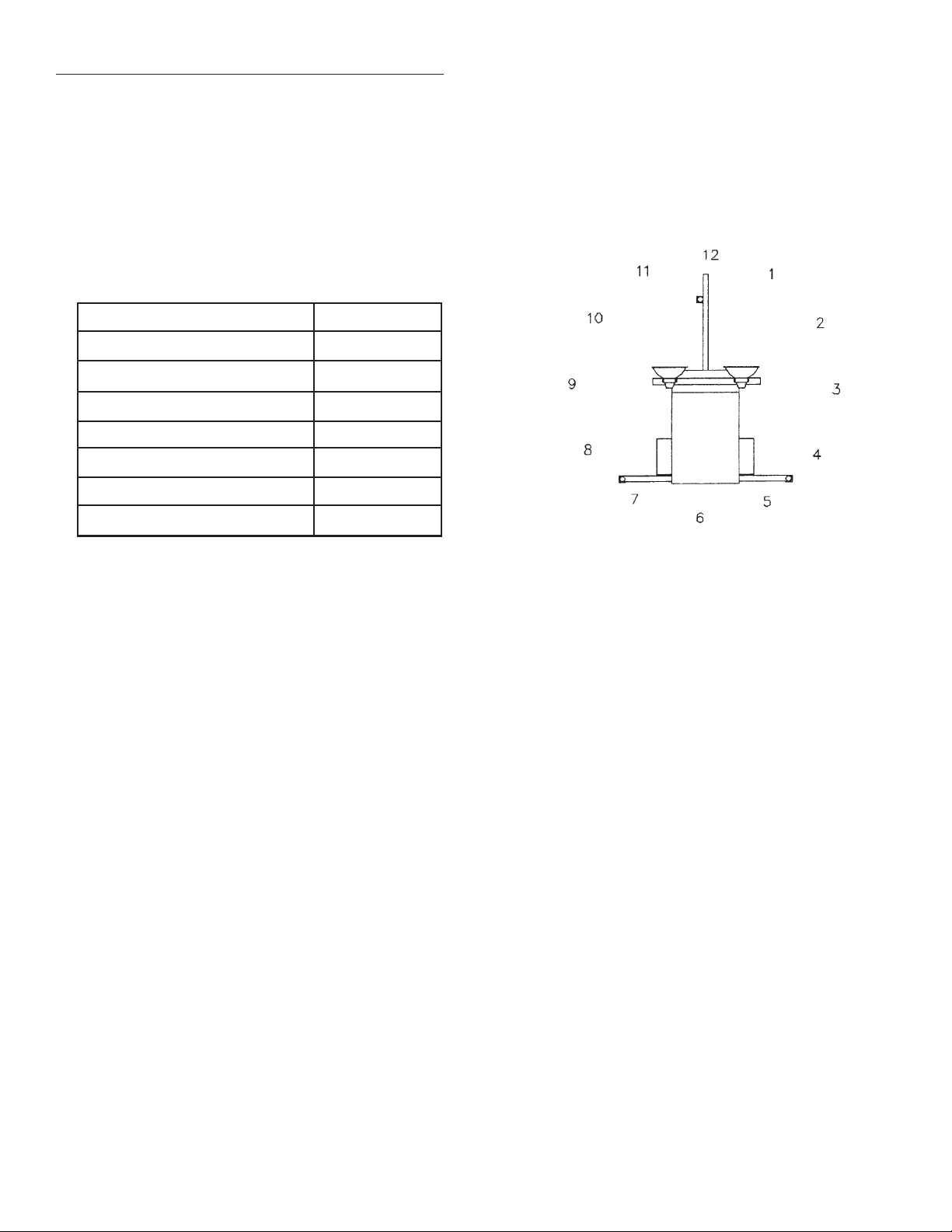
All wind load calculations were performed with the winch at 12 o’clock, the wind coming from the
direction shown with the lights flat-facing into the wind.
WIND DIRECTION SPEED
FROM 12 O’CLOCK 83 MPH
FROM 1 & 11 O’CLOCK 99 MPH
FROM 2 & 10 O’CLOCK 109 MPH
FROM 3 & 9 O’CLOCK 72 MPH
FROM 4 & 8 O’CLOCK 73 MPH
FROM 5 & 7 O’CLOCK 101 MPH
FROM 6 O’CLOCK 108 MPH
55
Page 56

BROKEN CABLE REPLACEMENT PROCEDURE
1. PREPARATION
1.1 Collapse tower to where mast is retracted, then pivot tower to horizontal position.
1.2 Remove the tower from the trailer and place it on a work surface such as two saw horses.
2. REMOVING TOP CABLE AND T OP MAST SECTION
2.1 T ie middle section and large section together by wrapping band, cable, chain, or rope around the
sheave brackets on these two sections. This insures that the middle section stays inside the large
section during removal of the small section.
2.2 Remove or lock the telescope lock pin open. This is the pin that locks the three sections together
during travel.
2.3 Drill out the aluminum pop rivets holding the plastic guides at the top of the middle section. Using
a screwdriver, remove these guides.
2.4 Remove the clevis pin anchoring the cable to the top of the middle section and remove the clevis
pin and the sheave from the middle section.
2.5 Pass the free end of the cable through the sheave slot between the middle and small section, and out
of the top of the tower. Pull the cable and the small section completely out of the middle section
together. Be sure to keep the cable tight; if slack accumulates it is most difficult to remove.
2.6 Unfasten the cable by removing the bolt at the base of the small section.
3. REINST ALLING THE SMALL SECTION
3.1 Fasten new cable to the base of the small section.
3.2 Reversing the procedure described in steps 2.1 through 2.5, reinstall the small section.
3.3 Reinstall the plastic guides with new pop rivets. New plastic guides should be used, but the old
guides can be used if their mounting position is shifted to the point where new holes can be drilled
in the tower section to provide a good fit when installing new pop rivets.
4. REMOVING THE LOWER CABLE AND MIDDLE T OWER SECTION
4.1 Remove or lock open the telescope lock pin if not previously done in step 2.2.
4.2 Drill out the aluminum pop rivets holding the plastic guides at the top of the large section. Using a
screwdriver, remove these guides.
4.3 Remove the cable from winch drum.
4.4 Remove the sheave clevis pin and the sheave from the top of the large section.
4.5 If the old cable is not frayed between the winch and the bottom mast pulley, attach a flexible “fish
wire” or “snake” (wire, rope cord, etc.) to the end of the cable to be used to thread the new cable
through the lower tower and pulleys. This can be done by “untwisting” the cable and inserting the
wire or cord into the middle of the cable and thus letting the cable twist back tightly around the fish
wire. If the old cable is frayed, cut off the frayed portion and proceed as above and then remove
tower and cable as instructed in section 4.6.
56
Page 57

4.6 Pass the free end of the cable through the sheave slot between the large and middle sections and
out of the top of the tower. Pull the cable and the middle section completely out of the large
section altogether. Be sure to keep the cable tight, if slack accumulates it is most difficult to
remove.
4.7 If the fish wire doesn’t work, it is necessary to remove the square mast section from the round mast
section. Remove the pivot pin from the pivot post and lift the mast from the pivot post and place
the assembly on a work surface. Remove the hex nut from the bottom of the round section, remove the “T” bolt at the top of the round section, and pull the square mast assembly out of the
round section, and proceed as instructed in section 4.6.
4.8 Unfasten the cable by removing the bolt at the base of the middle section.
5. REINST ALLING THE LOWER CABLE AND MIDDLE SECTION
5.1 If the “fish wire” worked, attach the cable to the fish wire and pull through the pulleys and the
round section.
5.2 If the square tower section was removed from the round section, thread the cable through the
pulleys at the bottom of the large section and out of the tubular stud. Reinstall the large square
section into the round section. Install the “T” locking bolt, and the hex nut on the bottom of the
round section. The hex-locking nut should be tightened and then backed off approximately onehalf turn or until the tower rotates freely .
5.3 Fasten the new cable to the base of the middle section.
5.4 Reversing the procedures detailed in sections 4.4 through 4.7, reinstall the middle section.
5.5 Fasten the new cable to the winch drum.
5.6 Reinstall the plastic shims as described in section 3.3.
57
Page 58

LIGHT FIXTURE TROUBLESHOOTING
DANGER! Do not open fixtures while light circuit breaker is “ON”. Allow lamp to cool before touching.
**T AKE EXTRA PRECAUTIONS WHEN TROUBLESHOOTING ELECTRICAL PROBLEMS**
A.Only use a voltmeter with two well-insulated pin probes rated for 600 volts.
B. Treat all conductors as potentially hot.
C. Proceed through circuits systematically, operating only one section at a time.
D.Before disconnecting ballast, turn off circuit breaker and wait 30 seconds for capacitor to dischar ge.
E. If all the lights are out and all the ballasts are receiving power, suspect burned out power cable.
SYMPTOM CAUSES CORRECTIVE ACTION
LAMP WILL Check Ballast Status Light a.Input lights should be on. This confirms power is going
NOT START to the ballast.
b.Output lights should be on. This confirms power is
coming from ballasts.
c.Output lights should be normal brightness. If one or
more of the output lights stay extra-bright, then the lamp is
not striking.
d.Use this knowledge to diagnose problem.
e.If ballast status light is out, but the floodlight lamp is
working, suspect burned out ballast status lamp and replace
Lamp loose in socket Inspect lamp base to see if there is arcing at center contact
button. Tighten lamp snugly. Check socket for damage.
Replace if defective.
Floodlight Plugs not tight Check plug and receptacle. Tighten if loose.
Defective Ballast Interchange ballast plugs in generator enclosure. If lamp
starts, replace ballast. Check ballast wiring diagram. Check
for swollen capacitors, charred wiring, core and coil, or
other signs of excessive heat.
Low Voltage Check line voltage at ballast input. Voltage should be
within 10% of nameplate rating when operating at normal
load. Increase supply voltage or remove external load.
Improper ballast Proper HID lamps will perform erratically or fail to start on
an improper ballast. The ballast nameplate data should
agree with the line voltage and lamp used. Improper ballast
will cause lamp to fail.
Improper lamp operating Operating position should agree with lamp etch. A BUHOR
position lamp can be operated base up vertical to and including the
horizontal and BD can be operated base down and vertical
to, approaching, but not including the horizontal. A lamp
operated beyond the specified position may not start.
Lamp has been operating; HID lamps require 4 to 8 minutes cool-down time before
cool down time insufficient restarting. Switch off breaker and allow lamp to cool.
58
Page 59

LIGHT FIXTURE TROUBLESHOOTING (cont’d)
SYMPTOM CAUSES CORRECTIVE ACTION
LAMP STARTS Defective Lamp Lamp may glow for extended period of time. Replace after
SLOWLY (ARC checking voltage and ballast.
DOES NOT
STRIKE WHEN
SWITCH IS
FIRST TURNED ON)
CIRCUIT Short circuit or ground Checking wiring against diagram. Check for shorts or ground.
BREAKER
TRIPS ON LAMP
START-UP
LAMP LIGHT Normal lamp depreciation Replace lamp
OUTPUT LOW
Dirty lamp or fixture Clean lamp and fixture
Defective ballast Interchange ballast plugs in generator enclosure. If lamp
returns to normal light output, replace ballast. Check for
swollen capacitors, charred wiring, core and coil, or other
signs of excessive heat.
Wrong Voltage Check voltage at ballast input. Voltage should be within 10%
of nameplate rating. Check wiring connections for voltage
loss. Check socket contact point.
Improper ballast Check ballast nameplate against lamp data.
LAMP COLORS Normal lamp depreciation Lamp color and brightness decreases and colors change
DIFFERENT slightly as lamps age. Spot replacement with new lamps may
cause noticeable differences in lamp colors. Group replacement minimizes color differences.
Dirty fixture Dirty fixtures will cause lamps to appear different in color.
Clean fixture.
Wrong lamp Check data on lamps, which appear different in color .
Replace with correct color lamp.
ARC TUBE Over voltage from Check voltage at ballast. Check for current or voltage surges.
DISCOLORED power supply Check for shorted capacitors and replace if defective.
OR SWOLLEN
Improper ballast Lamp operated on ballast designed for higher wattage lamp.
Check ballast nameplate against lamp data.
59
Page 60

LIGHT FIXTURE TROUBLESHOOTING (cont’d)
SYMPTOM CAUSES CORRECTIVE ACTIONS
SHORT LAMP Lamp damaged Check for outer bulb cracks. If air enters outer bulb, arc tube
LIFE may continue to burn for 100 hours before failure. Check for
bulb cracks where glass meets the base due to tightening lamp
too firmly in socket. Look for broken arc tube or loose metal
parts. Replace lamp.
Improper ballast Ballast nameplate data should agree with lamp line voltage
and lamp use. If improper ballast is used, the lamp life will be
shortened. A mismatch may also cause the ballast to fail.
LAMP Improper ballast Improper ballasting can cause flickering or erratic operation.
FLICKERS AND In the start-up period the lamp may ignite, start to warm-up
GOES OUT and then extinguish (cycle).
INTERMITTET
New lamp Under certain conditions new lamps may “cycle”. Usually
after three (3) tries to start at 30 to 60 second intervals, lamps
will stabilize and operate satisfactorily.
Defective lamp Replace lamp.
60
Page 61

TRACEABLE NUMBERED WIRING SYSTEM
(Using plug in ballasts to troubleshoot)
When troubleshooting the preceeding problems, minimize down time by following the traceable numbered
wiring system, always follow these steps:
STEP1: Insure all ballasts, which are numbered, are plugged into lead wires with corresponding
numbers.
STEP 2: Looking at the lights from the glass side and following the diagram below, plug each
fixture into the appropriately numbered plug at the top of the tower.
By adhering to the traceable numbered wiring system, troubleshooting, fixture aiming, and fixture control will
follow a standard predictable pattern.
61
Page 62

Rear Bearing Inspection Requirements
Leroy-Somer 6 & 8 kw Generators
The rear bearing on all 6 & 8 kw generators should be inspected every two (2) years or 2000 hours, whichever occurs
first. The bearing should be replaced at three (3) years or 3000 hours. Careful attention to this inspection proeedure will
prevent total generator failure resulting from bearing or bearing carrier deterioration.
There are two areas to examine during the inspection. First is the clearance between the bearing outer case and
thegenerator bearing carrier (NDE Bracket). The bearing should fit snugly into the carrier so that it can be rotated only
with some resistance. Side to side movement should be less than .010". If the bearing can be moved easily inside the
carrier or if there is visible evidence of bearing carrier wear, the housing carrier should be replaced with End Kit #836835
(which includes the carrier, bearing and 0-Ring). The second area of concern is the bearing itself. If roughness can be felt
when rotating the outer race of the bearing, the bearing needs to be replaced (#836828). The other area to check is to see
if the outer race will rock back and forth along the bearing axis. If there is movement in this axis, replace the bearing. If
neither of these conditions exist, replace the bearing retaining 0-Ring (#836830) and reassemble. Note: These bearings are
sealed units and cannot be field serviced.
Follow the same procedure at three (3) years or 3000 hours. At this time replace both the bearing and O-Ring as well as
inspecting the bearing carrier.
62
Page 63

WARRANTY PROCEDURE
The specific language of this warranty will determine TEREX LIGHT CONSTRUCTION's obligation in connection
with its product. The information presented below should be used as a general guide for implementation of policy.
In the event of a component failure during the warranty period it should be repaired as soon as possible, preferably
at an authorized TEREX LIGHT CONSTRUCTION service center. If component is manufactured by a company
other than TEREX LIGHT CONSTRUCTION, such as Deutz, Honda, Isuzu, Leroy Somer, Lister Petter,
Lombardini, Wisconsin, etc., the applicant should pursue repair and/or reimbursement through that manufacturer,
and its dealer/distributor network
To file a claim with TEREX LIGHT CONSTRUCTION, an WARRANTY APPLICATION (WA) form must be
completed in it’s entirety. Return the completed form within fourteen days of the repair to:
ATTENTION: WARRANTY
TEREX LIGHT CONSTRUCTION
590 Huey Road
Rock Hill Industrial Park
Rock Hill, SC 29730
TEREX LIGHT CONSTRUCTION will review the AWA form. Should we desire to inspect the defective parts, we
will issue you a return authorization for the defective parts. After inspecting the defective part(s), and it is determined
that warranty is due, we will then, at the discretion of TEREX LIGHT CONSTRUCTION , credit the applicants
account or send replacement parts.
.
TEREX LIGHT CONSTRUCTION warranty reimbursements:
1. $40.00 for each hour’s labor we allow toward a repair.
2. Distributors cost of parts not more than the price currently available from TEREX LIGHT
CONSTRUCTION.
3. One way surface freight charges on parts returned to TEREX LIGHT CONSTRUCTION.
Many repairs are assigned a predetermined labor schedule which is an average time in which a skilled technician
should be able to make a repair. TEREX LIGHT CONSTRUCTION will reimburse not to exceed the predetermined
number of hours for a particular repair.
TEREX LIGHT CONSTRUCTION does not reimburse for:
1. Travel, travel time, nor travel labor.
2. Mileage.
3. Excessive diagnostic time.
4. Repairs of defects, malfunctions, or failures resulting from accidents, abuse, misuse, modifications, alterations, improper servicing or lack of performance of required maintenance service.
5. Repairs where defective parts were not shipped back when requested by TEREX LIGHT CONSTRUCTION.
6. Regular maintenance such as parts or labor for oil changes, filter changes or filters.
7. Repairs where defective parts were not received by TEREX LIGHT CONSTRUCTION after
TEREX LIGHT CONSTRUCTION issued a return authorization.
63
Page 64

TEREX Amida
P.O. Box 3147
Rock Hill, SC 29730
MANUFACTURER’S LIMITED WARRANTY
TEREX Amida warrants to the original purchaser that goods manufactured by it will be free from defects
in workmanship and material for a period of one year after invoice from TEREX Amida, provided such
goods are installed, operated and maintained in accordance with TEREX Amida’s written instructions.
TEREX Amida makes warranty with respect to components and accessories furnished to TEREX
Amida, by third parties only to the extent of the original manufacturer’s warranty to TEREX Amida.
Third party components and accessories are parts such as fixtures, ballasts, engines, hydraulic pumps,
fuel pumps, alternators, generators, winches, tires and electrical components. TEREX Amida makes no
other warranty , express or implied, and makes no warranty of merchantability or fitness for any particular purpose.
Warranty for repair or replacement parts after warranty period shall extend for 90 days after invoice
date.
Manufacturer’s liability and purchaser’s sole and exclusive remedy for a failure of goods to perform as
warranted for any and all other claims arising out of the purchase and use of the goods, including negligence on the part of TEREX Amida, shall be limited to the repair of replacement of goods returned,
transportation prepaid to TEREX Amida. TEREX Amida shall in no event be liable for incidental or
consequential damages.
No employee or representative is authorized to change this warranty in any way or grant any other
warranty unless such change is made in writing and signed by an officer of TEREX Amida, at it’s home
office.
64
 Loading...