

Page 1

1000/3000 RX and TX
Quick Start Guide
Page 2
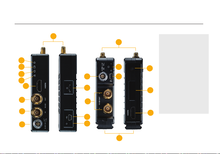
PHYSICAL PROPERTIES
Bolt 1000/3000 XT - TX
B
C
D
E
F
G
H
I
A
Bolt 1000/3000 XT - RX
I
J
G
K
A
J
K
A: RP-SMA connectors
B: Power status LED
C: Video status LED
D: Link status LED
E: Fault LED
F: HDMI input
M
G: 3G-SDI output
H: 3G-SDI input
I: Power input
J: Power switch
K: Mini-USB
N
L: Reset button
M: Menu joystick
N: OLED display
O: NATO rail
F
L
O
Page 3

TABLE OF CONTENTS
Power and Connect ............................. 2
Device Operation .................................. 2
Bolt Connector/Pin-Out ...................... 3
Custom 3rd Party Cables ..................... 3
Mounting ............................................... 4
Display Operation ................................ 5
Bolt Manager ....................................... 7
Page 4

POWER AND CONNECT
1
Connect the output from your video source to either the SDI or HDMI input (H or F) on the Bolt
transmitter. Connect either the SDI or HDMI output (G or F) from the Bolt receiver to the video input
on your monitor.
NOTE: If mounted upright on a stand above the monitor, use a right-angle SDI adapter to
relieve any strain caused by the weight of the cable, and to avoid damaging the SDI output’s
internal connectors.
2
Power the Bolt transmitter and receiver with the included A/C adapter, or if both devices are
equipped with battery plate accessories, attach a compatible battery (Gold or V mount for the
receiver, LP-E6 or Sony L-series for the transmitter).
3
Attach the two TX antennas to the transmitter and the ve RX antennas to the receiver via the
threaded RP-SMA connectors (A).
4
Move the power switches on both the transmitter and receiver (J) to the ON position. Video appears
within a few seconds.
DEVICE OPERATION
• Keep the transmitter and receiver at close range for 60 seconds after powering on the devices. This
allows them to scan for and select the best wireless channel.
• For best results when using multiple Bolt systems in the same area, place the transmitters and
receivers a few feet apart from each other.
• Operation of other wireless equipment may interfere with the Bolt. Try to separate other wireless
transmitters and receivers as much as possible.
2
Page 5
BOLT CONNECTOR/PIN-OUT
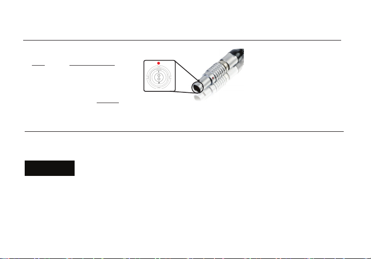
Bolt uses a 2−pin power connector
Pin Description
1* GND
2 +DC
* Pin 1 is closest to the red dot on the connector
CUSTOM/THIRD PARTY CABLES
• Test the power cable polarity with ONLY the power cable connected to Bolt. Do not connect video cables.
• Check the power cable for shorts and proper grounding.
CAUTION:
Using a reverse polarity or improperly−constructed power cable can damage the
product and is not covered under warranty.
3
Page 6
MOUNTING
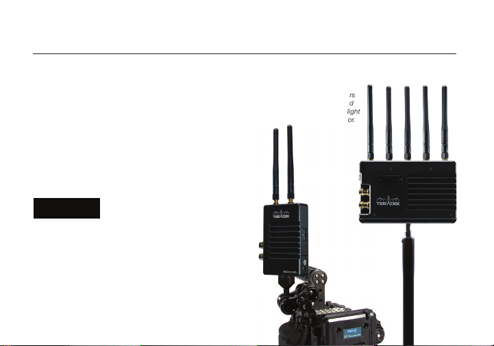
Bolt has a 1/4”-20 threaded hole on the bottom for mounting the included light stand adapter or any
other mounting accessory.
• Mount the Bolt transmitter vertically, keeping the
antennas clear of any obstructions.
• Orient the transmitter and receiver antennas so
they are parallel to each other.
• For best results, orient the transmitter antennas
so each one has clear line−of−sight to the
receiver.
• DO NOT OVERTIGHTEN
CAUTION:
SCREWS INSERTED INTO
THE TRANSMITTER’S 1/4”-20 THREADED
HOLE. Doing so can damage the transmitter’s
chassis and internal components, voiding the
warranty.
4
Bolt XT receivers
can be mounted
vertically on a light
stand or monitor.
Bolt XT transmitters
mount vertically on
a camera
Page 7

DISPLAY OPERATION
Receiver Status Screens - Cycle through status screens or return from the menu by pressing
the Menu joystick (M).
• Main Status Screen - This screen displays the status of the wireless receiver, along with the current
video resolution, frequency, link quality (if connected).
• Time Code Screen - Displays the current time code if received from the transmitter.
• Temperature Status Screen - Displays the current internal temperature of the unit.
• TX Info - Displays the name of the transmitter.
Menu Operation - Launch, then navigate through the menu with the Menu joystick (M).
• HDMI/SDI Out Format - Select the video output format. You can choose to match the video source
resolution by selecting Same as Input, or choose from the resolutions listed.
• 3D LUT Settings - Select and apply a specic look.
• Spectrum Analyzer - Determine which frequencies are available to use.
• Channel Selection - Select a bandwidth or frequency option
• Test Pattern - Select a video format to output a test pattern. Remove the test pattern by pressing left
on the Menu Joystick.
• Pairing - Pair your receiver with another transmitter. Once Pairing is activated on the receiver, turn
on the transmitter and use a paper clip to hold the reset button (L) for one second and release. The
warning and link LEDs will blink to indicate that pairing is active.
• Audio Settings - Congure Bolt’s Audio settings. If Beep on REC is activated, you will hear a short
tone whenever the camera begins or stops recording. The Mute Settings allow you to select between
completely muting the audio, not muting the audio, or muting the audio while recording.
5
Page 8

• Video OSD Settings - Choose when to display the OSD. By default, the OSD is displayed when no
video is received. Selecting the Never show option disables the OSD. The Show when operating
option hides the OSD until it is activated by the joystick. Selecting Show when no video will display
the OSD when there is no video feed, and will hide OSD when video appears (default). If Always show
OSD is selected, the OSD will always be displayed unless temporarily deactivated by the Menu joystick.
• Display Settings - Use the Display Settings to control the OLED display operation. You can set the
display to invert every 30 minutes (lengthens the display life), or it can dim or turn o after 10 seconds
or 10 minutes.
• Keys/Unit Orientation - Modify the operation of the joystick to correspond with the way the receiver is
mounted (horizontal or vertical).
• Reset All Settings - Reset all congurable options to their factory defaults.
• Device Info - Displays the model and serial number.
6
Page 9

BOLT MANAGER
Bolt Manager allows you to congure, pair, and upgrade your Bolt device. Bolt Manager is available as
software for Mac and Windows at www.teradek.com/pages/downloads, or for purchase as a standalone
device. NOTE: Available conguration settings will dier between Bolt models.
The following conguration settings are available:
• SELECT REGION - Congure Bolt to comply with your region’s regulations governing use of the
5GHz spectrum.
• SELECT FREQUENCIES - Congure the transmitter and receiver to use the same frequencies.
• SELECT TX NAME - Modify the transmitter’s name to make it easier to identify among other Bolt
systems that are present.
• SELECT QUALITY - Modify or balance the range and reliability of your signal. Select Maximum
Range when other sources of interference might be present, or Maximum Quality for complex, high
contrast situations.
• SELECT BROADCAST MODE - Increase transmission range and prevent multiple receivers from
interfering with each other when placed close to one another.
7
Page 10

Teradek regularly releases new rmware versions to improve performance, add new features, or to x vulnerabilities.
Visit teradek.com to update your device with the latest rmware.
NEED MORE HELP?
SUPPORT: http://support.teradek.com → Contains tips, information and all the latest rmware & software updates.
TERADEK SUPPORT STAFF: [email protected] or call 888-941-2111 ext. 2 (Mon-Fri 6am to 6pm PST)
Page 11

© 2019 Teradek, LLC. All rights reserved.
v 1.5
7
 Loading...