

Page 1

v.1
CTRL.1 CONTROLLER KIT
Quick Start Guide
© 2018 Teradek, LLC. All rights reserved.
Page 2

Page 3

TABLE OF CONTENTS
Physical Properties .............................. 2
Power and Connect ............................. 3
Pair Controller and Latitude ................ 3
Camera Run/Stop ................................ 4
Lens Mapping Feature ......................... 4
Controller Menu Operation .................. 5
Wireless Conguration ........................ 6
Standalone Operating Modes ............. 6
Page 4
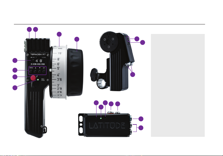
PHYSICAL PROPERTIES
E
F
CTRL.1
A
B
C
D
NEED MORE HELP?
G
H
LATITUDE MDR-M
MOTR.X
A: OLED display
I
J
B: Menu buttons (Menu,
Up, Down, and Set)
C: Record/Power button
D: Controller Status LED
E: Mini-B USB
F: Wired-mode port
K
G: Lens ring
H: Control knob
I: Motor class indicators
J: Axis button
K: Data/Power connectors
N
L
P
O
M
L: Operating Mode button
M: Receiver Status LED
N: Reset button
O: Power input
Q
P: CAM/Control port
Q: Motor port
R
R: Accessory ports
2
Page 5
POWER AND CONNECT
1
Connect power to Latitude’s PWR port (N).
2
Attach the motor(s) to the rods/lens.
3
Connect the motor to Latitude using a 4-pin connector. If connecting two motors, use a Y-cable
4-pin connector to connect both motors. The motor(s) will then begin calibrating.
4
Insert an LP-E6 battery in the controller and hold down the POWER button for two seconds. If
using a Latitude MB, you must also insert an LP-E6 battery into the unit.
PAIR CONTROLLER AND RECEIVER
There are two pairing methods if the controller is new or has not been paired to a receiver.
Wireless Pairing
Press the MENU button on the controller, then navigate to WIRELESS>FIND RECV to scan for active
receivers and automatically pair. The LED on the controller will turn green once paired.
Wired Pairing
Connect a 5-pin connector from the controller’s wired-mode input (H) to the IN-1 input on Latitude.
The controller and receiver will remain paired even after disconnecting the 5-pin connector. The LEDs
on the controller and receiver will turn blue once paired.
3
Page 6
CAMERA RUN/STOP
1
Connect a camera cable from the CAM/Control port on the Latitude to the camera, then
navigate to MENU>CAMERA on the CTRL.1 to indicate which camera you have connected.
2
Press the REC button on the controller (C) to start/stop recording on the camera.
NOTE: If using a RED camera, the camera serial communication setting must be set to RCP
(Redlink Command Protocol) for the unit to operate.
LENS MAPPING
The Lens Mapping Package can be purchased with the CTRL.1, or as a seperate upgrade. After
purchasing the Lens Mapping Package, use the following steps to activate it.
1
Press the MENU button, then use the ▼ button to navigate to the ADV (Advanced) menu. Press
the SET button to access the menu.
2
Navigate to the LICENSES menu. Press SET to display the UID number.
3
To generate a license key, enter the controller’s UID, the upgrade code, and your email address
on activate.teradek.com.
4
On the same screen displaying the UID number, select YES to enter the license key.
4
Page 7

CONTROLLER MENU OPERATION
Press the MENU button, then use the ▲, ▼ and SET button to navigate through the dierent
menu options.
• POWER OFF - Power OFF the controller
• LENS - Congure lens mapping function
• MOTORS - Congure the attached motor(s)
• INPUTS - Congure the controller’s knob
• WIRELESS - Congure the wireless settings
• CAMERA - Select the make of the camera
• LIMIT - Congure the knob’s range
Controller Status LED
The controller status LED indicates when the system is ON and provides the system’s current status
during operation.
• OFF - Unit is powered o
• YELLOW - No wireless connection
• RED - Camera is recording
• ORANGE - PC/Bootloader mode
5
• SCREEN - Change display settings
• BUTTONS - Assign functions to the buttons
• RX CONFIG - Congure auxiliary controllers,
such as a thumbwheel or zoom rocker
• ADV - Contains device info menu, licenses,
and advanced functions for debugging
• WHITE - Checking RF module status
• GREEN - Wireless is synched
• BLUE - Wired-mode connection.
Page 8

STANDALONE OPERATING MODES
LATITUDE M and MB receivers have several dierent operating modes. To change the receiver’s
operating mode, press the recessed operating mode button (K).
Standard Mode - GREEN LIGHT
This is the default operating mode. LATITUDE will accept controller (wireless) and/or thumbwheel
commands, and forward them to the motor(s) and camera. Standard mode also enables LATITUDE’s
Wi-Fi access point, adding full Wi-Fi/FoolControl capability to DSMC and DSMC2 cameras.
Flight Mode - CYA N LI G HT
In Flight Mode, the Latitude will disable its wireless module. This is useful for saving battery power if
the system is being controlled via wired mode. No wireless data will be transmitted.
Transmitter Mode - PURPLE LIGHT
In Transmitter Mode, the LATITUDE will route the input signals (i.e. plugged into IN-1, IN-2) over the
RF link to the LATITUDE on camera. This enables many unique congurations, including using two
thumbwheels (plus LATITUDE) on a director’s monitor to control Focus/Iris and run/stop.
6
Page 9
STANDALONE OPERATING MODES (CONT.)
Longe Range FoolControl - PINK LIGHT
If you connect your iOS device to LATITUDE’s Access Point
while in Transmitter mode, the LATITUDE will re-transmit the
FoolControl communications over the long-range RF link
to a LATITUDE on-camera, increasing the usable range of
FoolControl, This increases the usable range of FoolControl,
and is particularly suited for drone work.
Teradek regularly releases new rmware versions to improve performance, add new features,
or to x vulnerabilities. Visit https://www.teradek.com to update your device with the latest
rmware.
NEED MORE HELP?
SUPPORT: http://support.teradek.com → Contains tips, information and all the latest rmware
& software updates.
TERADEK SUPPORT STAFF: [email protected] or call 888-941-2111 ext.2 (Mon-Fri 6am to
6pm PST)
7
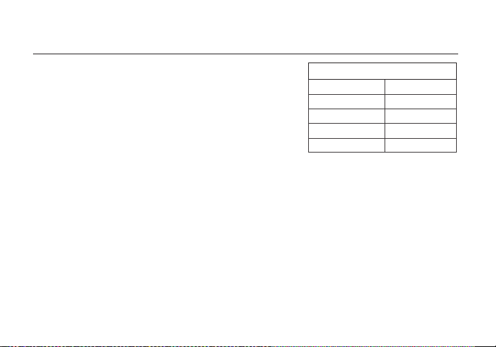
Wi-Fi DEFAULTS
SSID
Password
Admin URL
Admin username
Admin Password
LATITUDE-XXXXX
latitude
192.168.0.1
admin
PASSWORD
Page 10

 Loading...