

Ten Tec 599 Users Manual

Eagle
Model 599
Users Manual
Revision 1.002
599 / Eagle Users manual Release 1.002 – September 27, 2010 1
Part #74447
Printed in USA

Table of Contents
1. Your new Eagle 599 _________________________________________________________ 2
1.1. Unpacking Eagle 599 _____________________________________________________________ 2
1.2. About this Manual _______________________________________________________________ 2
1.3. Accessory package _______________________________________________________________ 2
1.4. Connection to Antenna & Power Supply_____________________________________________ 3
1.5. A word about grounding __________________________________________________________ 3
1.6. Philosophy of design _____________________________________________________________ 4
1.7. Configuration Menu _____________________________________________________________ 5
2. Easy Operation Guide _______________________________________________________ 6
2.1. General Operations ______________________________________________________________ 6
2.2. SSB Mode Operation____________________________________________________________ 13
2.3. CW Mode Operation ____________________________________________________________ 17
2.4. AM Mode Operation ____________________________________________________________ 18
2.5. FM Mode Operation ____________________________________________________________ 18
2.6. Mobile Operation_______________________________________________________________ 18
2.7. Digital Mode Operation__________________________________________________________ 18
2.8. Internal Hardware Noise Blanker _________________________________________________ 18
2.9. Internal Tuner _________________________________________________________________ 18
2.10. Optional Filter Installation ______________________________________________________ 19
Eagle Rear Panel ______________________________________________________________ 20
4. Accessory Devices _________________________________________________________ 22
4.1. Using the 712 USB/Soundcard Interface ____________________________________________ 22
4.2. Interfacing to a computer and firmware updates_____________________________________ 22
4.3. List of Optional Accessories For The Eagle _________________________________________ 24
5. Specifications _____________________________________________________________ 25
5.1. Transceiver Specifications _______________________________________________________ 25
5.2. Transceiver Block Diagram ______________________________________________________ 28
6. In Case of Difficulty________________________________________________________ 30
7. Warranty & Return Policy___________________________________________________ 32
8. Revision History ___________________________________________________________ 32
599 / Eagle Users manual Release 1.002 – September 27, 2010 1
Part #74447
Printed in USA
TEN-TEC
BW
PBT
A=B
VOX
PWR
RIT
AGC
PRE
SQL
MON
AF RF
MR
AN
NR
SP-CW
MIC
LOCK
ATTN
FAST
A/B
NB
MOD TUNE
FNC
1. Your new Eagle 599
1.1. Unpacking Eagle 599
Examine the Eagle transceiver for signs of
shipping damage. Should any damage be
apparent, notify the delivering carrier
immediately, stating the full extent of the
damage.
Retain all damaged cartons. Liability for the
shipping damage rests with the carrier. We
recommend that you keep the carton and
fillers in the event that storage, moving, or
shipment becomes necessary.
1.2. About this Manual
A complete description of the features and
functions on the Eagle 599 are included
within the pages of this manual. The latest
version of the Eagle manual is also available
to view in pdf format located under the
download tab on the Eagle Transceiver via
www.tentec.com.
You may also find firmware updates plus a
full set of schematic diagrams at this same
web location.
BAN
1.3. Accessory package
The additional hardware and accessories
listed in Fig 1-1 come standard with your new
Eagle.
Look over the items listed and refer to the 5
digit Ten-Tec part number and description
should you find the need to replace an
accessory. To purchase additional
accessories and parts or to report an item
missing from this list, please contact Ten-Tec
Service (865) 428-0364.
Qty Part # Description
1 702 Dynamic Hand Mic
1 27091 Auto Style Fuse, 25 Amp 32V
1 35241 8 PIN DIN Connector
1 35263 Plug – Stereo, 3.5MM (1/8)
1 38040 Allen Wrench, 0.050 Hex
1 41073 Fork Terminal
1 46214 Cable Assembly 4 Ft
1 74020 Warranty card
1 74244 Standard Warranty Sheet
1 74447 Manual for 599
1 74450 How do I become a Ten-Tec
Ambassador
1 74454 Eagle Quick Start Guide
Table 1.3-1 Eagle Packing List
599 / Eagle Users manual Release 1.002 – September 27, 2010 2
Part #74447
Printed in USA
1.4. Connection to Antenna &
1.5. A word about grounding
Power Supply
The Eagle is designed for use with any
antenna system providing a 50 Ohm resistive
impedance at the desired operating frequency.
Every effort should be made to ensure the
impedance of the antenna system is as close
as possible to the specified 50-Ohm value.
Note that the “G5RV” type antenna and some
Windom’s do not provide 50-Ohm impedance
on all HF Amateur bands, and an external
wide-range antenna coupler or the optional
model AT599K Eagle internal auto tuner may
be needed with this type antenna. Any
antenna to be used with the Eagle must,
ultimately, be fed with 50 Ohm coaxial cable.
The Eagle transceiver requires a source of
well-filtered and regulated DC voltage. The
supply voltage on the Eagle is 13.8 Vdc
nominal +/- 15% to allow for mobile and
battery operation. The voltage source must
be capable of supplying a minimum of 23
amperes continuous duty at full 100 watt
output for AM & FM modes. The model 940
or 941 Ten-Tec power supplies will meet or
exceed your voltage and current
requirements. We recommend using the
included DC power cable (P/N 46214). Use
of #12 stranded wire is recommended for
mobile and in home use to accommodate the
required current demand during transmit.
Note: Always enable the power source first
and then the transceiver. If a generator or
battery connected to a charger is used to
supply the DC source, always turn off the
transceiver before starting or shutting off the
DC source equipment. These recharging
devices often generate large voltage spikes
that can damage the transceiver.
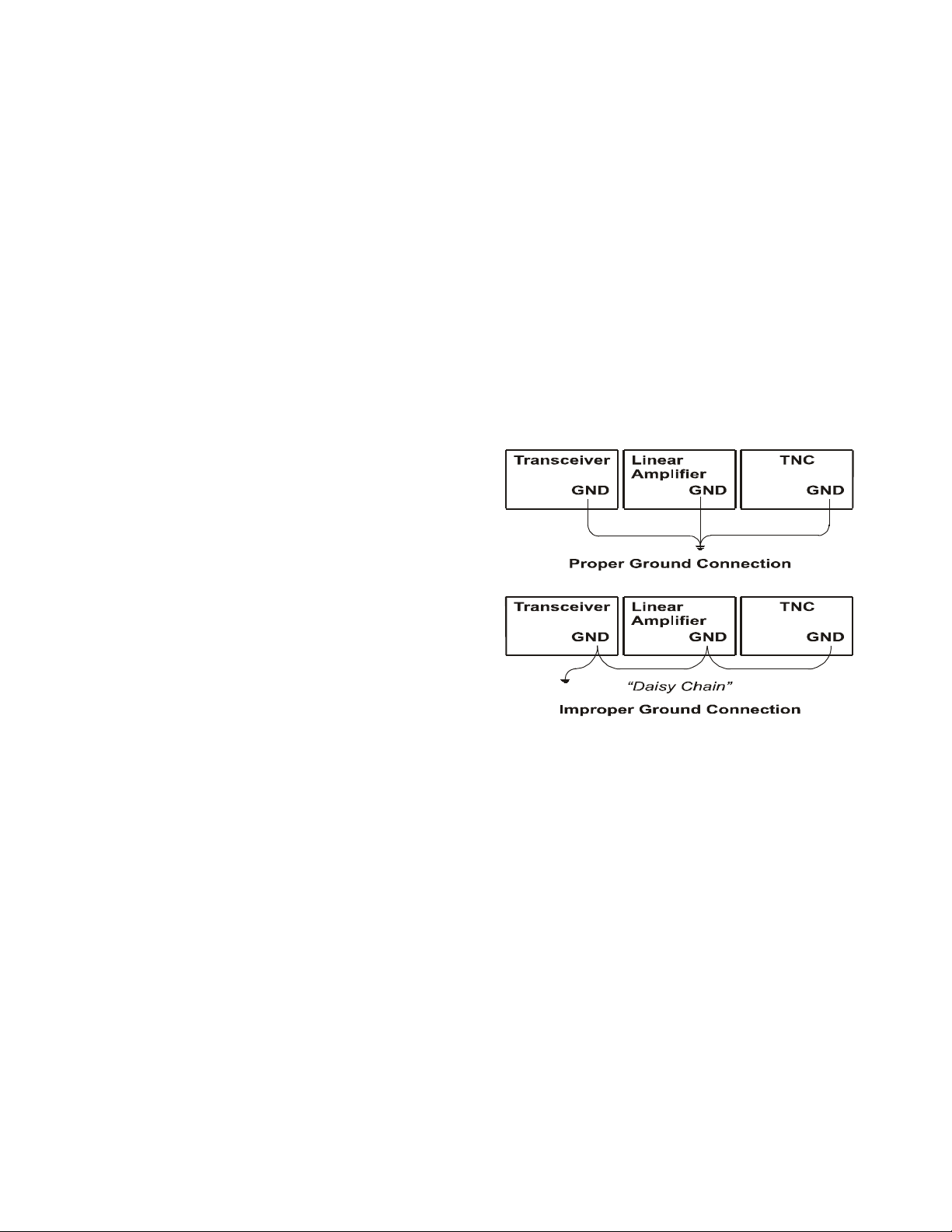
A good ground system is essential for
optimum operation of any HF transmitter.
The best solution is to connect all the station
equipment to a single ground connection. Do
not make ground connections by connecting
one device to another, then that device to
another, etc. and then finally to the ground
bus. This so called “Daisy-Chain” grounding
technique may nullify any attempt at effective
radio frequency grounding. See Figure 1.5-1
Grounding
Figure 1.5-1 Grounding
Remember that a connection to a copper cold
water pipe is no longer suitable and is in
violation of the National Electrical Code.
Many modern water connections use plastic
pipe, and are not suitable ground connections.
A good ground system can contribute to the
station efficiency in a number of ways
including minimizing the possibility of
electrical shock, and minimizing RF currents
flowing on the shied of the coax cable
causing interference to electronic equipment
and transceiver accessories.
599 / Eagle Users manual Release 1.002 – September 27, 2010 3
Part #74447
Printed in USA

1.6. Philosophy of design
With the Model 599 Eagle, Ten-Tec has
created a transceiver combining simplified
controls and ease of operation with the
excellent performance of a low first IF 160through 6-meter ham-band architecture in a
compact, mobile-friendly structure. The
analog portion of the radio is double
conversion with IF frequencies of 9.0015
MHz and 22.5 kHz. A third conversion to
zero-frequency IF is accomplished in the DSP
processor.
General coverage receive is provided between
0.5 and 30 MHz.
Refer to the Block Diagram in the
Specifications section for the following
discussion. Receive signals are routed
through the optional antenna tuner and
transmit lowpass filter to a switchable 10dB
attenuator at the input of the BPF/Preselector
board. This board also contains the bandpass
filter selected for the band in use and a
switchable 12dB receive preamplifier. On the
TX/RX board, output from the preamplifier is
mixed with the first Local Oscillator to
9.0015 MHz and routed optionally through
the noise blanker to one of three roofing
filters. After selectivity roofing, IF
amplification is provided by a variable gain
amplifier which also develops the high-level
AGC. Finally, the 9.0015 IF signal is mixed
with the second LO to develop a 22.5 kHz
low IF for the Signal Processing Unit (SPU).
Based on a 36.096 MHz temperature-stable
reference, the Synthesizer board generates
first and second LOs via fractional-N
synthesis and fixed frequency division. The
SPU samples the low IF at 96K samples per
second and applies the resulting data to a
digital signal processor. Numerical
algorithms running in the digital processor
accomplish additional selectivity filtering,
low-level AGC, and demodulation. The
resulting audio appears at the speaker and line
outputs.
The PIC processor in the CPU module
executes firmware stored in EEPROM to
perform housekeeping functions such as
synthesizer programming/tuning, signal
switching, and front panel display and control
input. Based on the control inputs from the
front panel (or remotely via the USB
interface), the CPU writes display
information, tunes the LOs, adjusts
selectivity, and chooses both receiver
detection and transmit emission modes.
Transmit operation is basically the reverse of
receive. Audio or CW signals are generated at
zero-frequency (baseband) in the DSP,
frequency-shifted to the 22.5 kHz low IF, and
output to mixers on the TX/RX board for
conversion to the operating frequency. The
signal then travels in the reverse direction
through the selected Bandpass Filter to the
low-level drivers and Power Amplifier, then
finally through the Lowpass Filter and
optional antenna tuner to the antenna. If the
tuner is installed, forward and reverse power
measurements from the SWR bridge are used
by the CPU to select the correct inductance
and capacitance in an L-network to provide a
50 Ohm load to the transmitter output
599 / Eagle Users manual Release 1.002 – September 27, 2010 4
Part #74447
Printed in USA

1.7. Configuration Menu
Upon purchase of your transceiver some
settings may have already been factory
installed and set into the Eagle. Optional
accessories such as an auto tuner, a specific
additional roofing filter, noise blanker, or
your favorite front display color combination
will need to be programmed into the Eagle.
To begin configuring the Eagle, start with the
Eagle powered off, press the FNC button, and
hold the FNC button continuously while
powering up the Eagle. When the Eagle is
first shipped from the factory, the front panel
display will show “F1 2.4” which indicates
the factory filter has been installed. Now
release the FNC button. To select a different
value for a given Configuration Menu item,
use the MULTI knob to scroll through the
choices. To advance to the next Configuration
Menu item, press the FNC button. Once the
settings in the Configuration Menu have been
set to the desired values, press any key on the
front panel except the FNC button to exit the
Configuration Menu.
The items contained in the Configuration
Menu and their options are shown in the
following table.
Item
Settings Notes:
Name
F1 nO / none
15.0/15KHz
6.0 / 6KHz
2.4 /2.4KHz
1.8 /1.8KHz
0.6 / 600Hz
0.3 / 300Hz
Refer to Section
“Optional Filter
Installation” for
more information on
physical installation
of each filter
2.4 KHz is standard,
others are optional
F2 Same as F1 Same as F1
Default is nO
F3 Same as F2 Same as F1
Default is nO
EA d Enable AM
detection
On / OFF
EF d Enable FM
detection
On / OFF
bl i Backlight
Intensity
Requires 6.0 KHz
Filter Default is
OFF
Requires 15.0 KHz
Filter Default is
OFF
Overall intensity of
the backlight.
0..15
bl r Backlight red
level 0..15
bl 9 Backlight
green level
Independent red level
adjustment
Independent green
level adjustment
0..15
bl b Backlight
blue level
Independent blue
level adjustment
0..15
Nb Noise
Blanker
Installed
Refer to section
“Internal Hardware
Noise Blanker”
OFF On
tu n Internal Auto
Tuner
Refer to section
“Internal Tuner”
Installed
OFF On
Table 1.7-1 Configuration Menu Items
599 / Eagle Users manual Release 1.002 – September 27, 2010 5
Part #74447
Printed in USA
TEN-TEC
BW
PBT
A=B
VOX
PWR
RIT
AGC
PRE
SQL
MON
AF RF
MR
AN
NR
SP-CW
MIC
LOCK
ATTN
FAST
A/B
NB
MOD TUNE
FNC
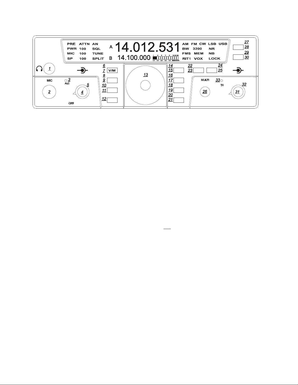
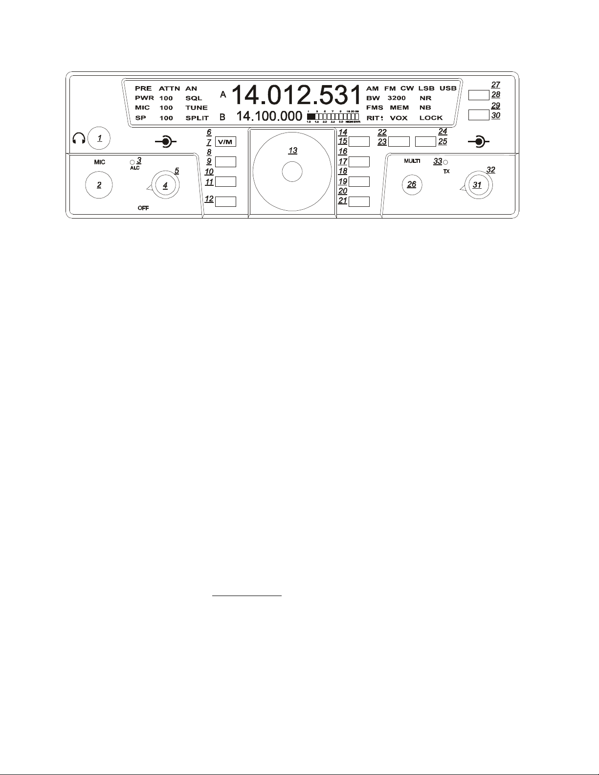
Figure 2.1 Eagle Front Panel
2. Easy Operation Guide
2.1. General Operations
This section of your Eagle Manual will
discuss the button operation and adjustments
common to all modes on the Eagle
Primary and Secondary Button
Functionality
Most buttons on the front panel can perform
multiple functions. The Primary Function for
the buttons on the Eagle is screened directly
on the button. They are lit when power is
applied to the radio. The Secondary Function
for the buttons is silk-screened above the
respective button on the front panel. The
FNC button is used to invoke the Secondary
Functions of the front panel buttons. The
functionality for both Primary and Secondary
buttons are described in the following
sections.
Master Reset (using LOCK (15) button)
To perform a master reset to the Eagle, begin
by pressing and holding down the LOCK
button at the same time you turn on the
power. Continue to hold down the LOCK
button until the screen says “reset”.
BAN
You have now performed a reset to the Eagle
which will also clear all memories and
settings you have placed in your transceiver.
Performing a reset means you will need to
enter the Configuration menu described in
Advanced Settings to program your filter
positions, accessories, screen colors, etc.
Keying a Linear Amplifier:
Pin 8 on ACC-1 will provide an open
collector output for keying a linear amplifier.
The Eagle provides a 17 ms closure delay
before RF is supplied to the linear amp.
Refer to Figure 3-2 for wiring to this
connector. Remember to use shielded cable
for making this connection. The amp key line
is not a relay similar to those found on many
older transceivers. It is a transistor switch
rated for a maximum of 24 volts and 250 mA
from the key line of your amplifier. Many
older amplifiers using an AC relay or relay
voltages exceeding the limits of the Eagle
must use an amplifier interface relay such as
the ARB-704 sold through the Ten-Tec
company P/N #R9901
S-Meter
The signal strength display on the Eagle will
offer two functions
1. The S-Meter will read the signal
strength in receive mode
2. The meter will also function as an
SWR meter when transmit tune is
activated.
599 / Eagle Users manual Release 1.002 – September 27, 2010 6
Part #74447
Printed in USA
TEN-TEC
BW
PBT
A=B
VOX
PWR
RIT
AGC
PRE
SQL
MON
AF RF
MR
AN
NR
SP-CW
MIC
LOCK
ATTN
FAST
A/B
NB
MOD TUNE
FNC
FNC (12)
The FNC or function button is a vital portion
of this radio. All Secondary Functions of the
Eagles button set are accomplished by
pressing the FNC button. When the FNC
button is first pressed, the FNC button will
begin flashing. You will also see FUNC
blinking on the main screen where the
Bandwidth Value is normally displayed.
Pressing a button using the Secondary
Function will execute that function, either
turning it on or off, or changing its mode, etc.
Pressing the FNC button once again will exit
that secondary feature.
PWR (24)
Power output will be shown on the Eagle
toward the left side of the display. It displays
the output in watts and can be adjusted and
shown as a numeric value from 5-100. To set
the power output simply press the FNC
button (a secondary button function) and then
press TUNE. The multi knob can now be
used to adjust the output. After the power
output has been selected you may exit by
pressing FNC. The digits appearing on the
left of the screen measures the average power
so you will notice the digits may flash a
smaller value when transmitting in side band
mode.
BAN
TUNE (25)
If the auto tuner for the Eagle is not turned on
or is not installed this button will generate a
carrier signal for tuning purposes at 20 watts.
This is providing the power output is set at a
minimum of 20 watts. If set lower, it will
transmit a lower level carrier. If the power
output is set anywhere from 20-100 watts the
Eagle will still only tune at 20 watts. This is
an easy and safe way to tune an external
outboard antenna tuner or solid state
amplifier. To increase this power output level
while in the tune positions press FNC (a
secondary button function) and then press
TUNE again. You may now adjust the power
level using the MULTI knob to vary the
output for tuning a linear amplifier.
If the auto tuner is installed and turned on in
the Configuration Menu the TUNE button
will now automatically match the Eagle to the
antenna you are using. You will hear some
clicking noise within the Eagle until the tuner
determines the best match. When finished the
TX light will flash twice plus you will hear a
beep tone from the Eagle. Remember when
using an external tuner or when tuning a
linear amplifier to always go into the
Configuration Menu and turn off the internal
auto tuner.
599 / Eagle Users manual Release 1.002 – September 27, 2010 7
Part #74447
Printed in USA

TEN-TEC
BW
PBT
A=B
VOX
PWR
RIT
AGC
PRE
SQL
MON
AF RF
MR
AN
NR
SP-CW
MIC
LOCK
ATTN
FAST
A/B
NB
MOD TUNE
FNC
RIT (22)
The receiver integrated tuning can be selected
as a secondary button function by pressing
FNC and then the MOD button. You will
notice RIT will begin to flash on the front
panel and you may now adjust the receiver in
10 Hz increments up or down frequency
using the MULTI knob. To zero out the RIT
simply press and hold the MOD button and
the display will zero out. To exit simply
press the FNC button
Multi (26)
Most features on the Eagle are directly
accessible, however, for those that are not the
MULTI KNOB is used to adjust specific
values. More about this will be addressed
within specific features throughout this
manual.
Band (21)
To change bands or toggle through the Ham
bands press the BAN button and the next
higher Amateur band will appear. To reverse
the direction press the function button FNC.
It will begin to flash. Next press the BAN
button to change directions. Exit the
secondary function feature by pressing FNC
once again. When the band is changed, the A
Frequency, the B Frequency and the Mode
are recalled from the last time the band was
used. Since the Mode is recalled, the Tuning
Rate, and the AGC will also be recalled from
the last time that Mode was used.
BAN
Split (28)
To operate SPLIT mode simply press and
hold the A/B button for 2 seconds. The word
SPLIT will appear next to the B VFO which
also indicates the frequency you will be
transmitting on. Remember when in SPLIT
mode you will always be transmitting on
VFO B.
A/B (28)
This Primary Function allows you to toggle
between VFO A and VFO B each time you
press the button.
A=B (27)
The secondary function of this button allows
you to copy the contents of VFO A to VFO B
To equal both VFO A and B press FNC
button until it begins to flash. Next, press
A/B button. Exit Function mode by pressing
FNC.
599 / Eagle Users manual Release 1.002 – September 27, 2010 8
Part #74447
Printed in USA

TEN-TEC
BW
PBT
A=B
VOX
PWR
RIT
AGC
PRE
SQL
MON
A/B
AF RF
MR
AN
NR
SP-CW
MIC
FNC
Lock (15)
To lock the VFO on a frequency so no
movement to the VFO knob varies the
frequency, press the LOCK button once to
lock the VFO. Press the LOCK button a
second time to release the lock feature. Lock
state is indicated by the text on the right side
of your screen when turned on.
Switching to Memory Operation (7)
Pressing the V/M button activates the
memory on the Eagle. Pressing the V/M one
time will switch into memory mode. MEM
with a number will appear on the front panel
screen. Rotating the MULTI knob will
address memory locations that hold receive
and transmit frequency pairs to control the
transceiver. Turning the MULTI control
shows the number (1 – 100) for the next
available or empty location. At this point, the
operator may either (A) copy the information
from both VFO’s to a memory location; or
(B) copy the memory information to the
VFO’s. To copy the memory channel back
into VFO mode simply press FNC (a
secondary button function) until FNC and
FUNC begin to flash. Next, press V/M
button. Exit Function mode by pressing
FNC. Your favorite memory can now be
tuned and modified with the VFO.
NB
LOCK
ATTN
FAST
BAN
MOD TUNE
Storing a Frequency to Memory (6)
When the main display holds a frequency you
wish to store into memory, press FNC, (a
secondary button function) plus V/M and the
MEM front display will show the number of
the last used storage location (1-100). You
may either accept this location by again
pressing the V/M button or change the
location by rotating the MULTI knob first.
An unused location displays a series of
dashed lines --.---.--- on the main display.
V/M stores the frequency of the active VFO
in the memory (along with current Mode and
Bandwidth).
Recalling a Stored Frequency (7)
You may recall a stored frequency from
memory by pressing the V/M button to switch
from VFO to Memory operation. With the
MEM lit on the screen your current memory
location and number will appear on screen.
Rotate the MULTI knob until the desired
memory frequency appears in the main
display, then press FNC (a secondary button
function) plus V/M to copy it into the VFO.
Exit Function mode by pressing FNC.
599 / Eagle Users manual Release 1.002 – September 27, 2010 9
Part #74447
Printed in USA
 Loading...