

Page 1

Table of Contents
1. Your new 418 ______________________________________________________________ 3
1.1. Unpacking 418 __________________________________________________________________ 3
1.2. About this Manual _______________________________________________________________ 3
1.3. Accessory package _______________________________________________________________ 3
1.4. Connection to Antenna & Power Supply_____________________________________________ 4
1.5. A word about grounding __________________________________________________________ 4
1.6. Philosophy of design _____________________________________________________________ 4
2. 418 FRONT PANEL ________________________________________________________ 6
2.1. Switches _______________________________________________________________________ 6
2.2. Band Buttons ___________________________________________________________________ 6
2.3. Attenuator Button _______________________________________________________________ 6
2.4. Delay Button____________________________________________________________________ 6
2.5. Delta Button ____________________________________________________________________ 6
2.6. Leds ___________________________________________________________________________ 6
2.7. Display ________________________________________________________________________ 6
2.8. Backlight_______________________________________________________________________ 6
3. 418 Rear Panel _____________________________________________________________ 7
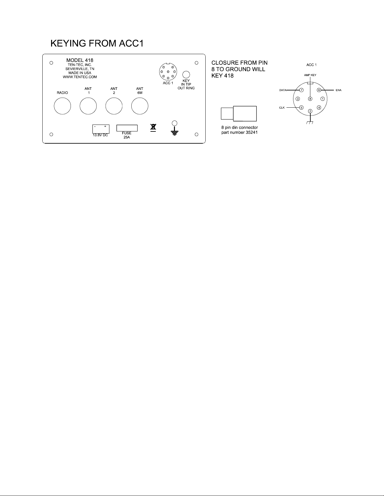
3.1. ACC 1 _________________________________________________________________________ 7
3.2. Key In / Out ____________________________________________________________________ 8
3.3. Power _________________________________________________________________________ 8
3.4. Fuse ___________________________________________________________________________ 8
3.5. Antennas _______________________________________________________________________ 8
4. Amplifier Hookup __________________________________________________________ 9
4.1. 418 to 539 ______________________________________________________________________ 9
4.2. 418 to other_____________________________________________________________________ 9
5. Fault ____________________________________________________________________ 11
5.1. Fault conditions ________________________________________________________________ 11
5.2. List of faults ___________________________________________________________________ 11
6. Specifications _____________________________________________________________ 12
7. Block Diagram ____________________________________________________________ 13
8. In Case of Difficulty________________________________________________________ 14
9. Warranty & Return Policy___________________________________________________ 14
418 Users manual Release 1.00 – NOVEMBER, 2011
Part #74468
Printed in USA 1
Page 2

NOTES:
418 Users manual Release 1.00 – NOVEMBER, 2011
Part #74468
Printed in USA 2
Page 3
1. Your new 418
1.1. Unpacking 418
Examine the 418 for signs of shipping
damage. Should any damage be apparent,
notify the delivering carrier immediately,
stating the full extent of the damage. Save all
damaged cartons and packing material.
Liability for any shipping damage rests with
the shipping carrier.
1.2. About this Manual
A complete description of the features and
functions on the 418 is included within the
pages of this manual. The latest version of
the 418 manual is also available for viewing
at www.TENTEC.com.
You may also find a full set of schematic
diagrams at this same web location.
1.3. Accessory package
The additional hardware and accessories
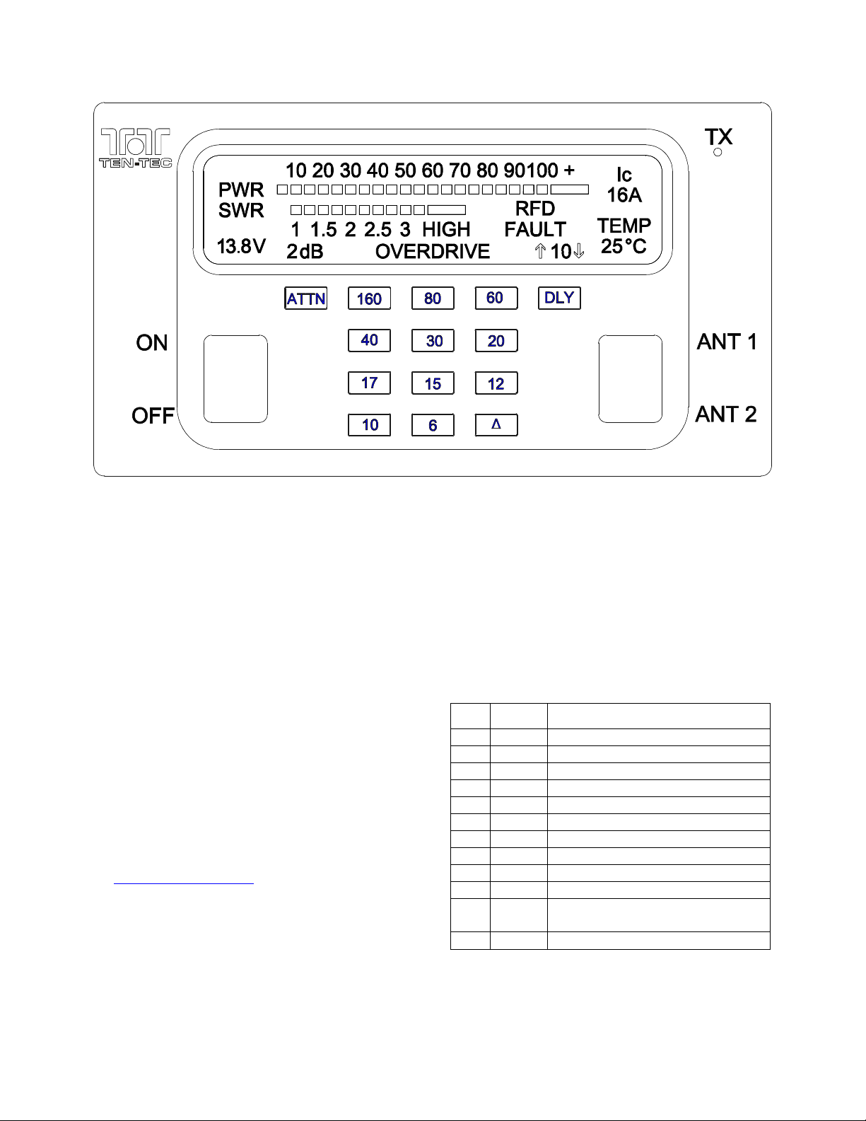
listed in Fig 1.3-1 come standard with your
new 418.Look over the items listed and refer
to the 5 digit TEN-TEC part number and
description should you find the need to
replace an accessory. To purchase additional
accessories and parts or to report an item
missing from this list, please contact Service
at TEN-TEC, INC.
Qty Part # Description
1 46216 3.5mm to 2 RCA jacks cable
1 27091 Auto Style Fuse, 25 Amp 32V
1 35241 8 PIN DIN Connector
1 35263 Plug – Stereo, 3.5MM (1/8)
1 46174 8 PIN DIN TO 8 PIN DIN cable
2 41073 Fork Terminal
1 46214 Power Cable
1 74020 Warranty card
1 74244 Standard Warranty Sheet
1 74468 Manual for 418
1 74450 How do I become a Ten-Tec
Ambassador
Table 1.3-1 418 Packing List
418 Users manual Release 1.00 – NOVEMBER, 2011
Part #74468
Printed in USA 3
Page 4

1.4. Connection to Antenna &
Power Supply
The 418 is designed for use with any antenna
system providing 50 Ohm resistive
impedance at the desired operating frequency.
Every effort should be made to ensure the
impedance of the antenna system is as close
as possible to the specified 50-Ohm value.
Note: that the “G5RV” type antenna and
some Windom’s do not provide 50-Ohm
impedance on all HF Amateur bands, and an
external wide-range antenna coupler may be
needed with this type antenna. Any antenna
to be used with the 418 must, ultimately, be
fed with 50 Ohm coaxial cable.
The 418 requires a source of well-filtered and
regulated DC voltage. The supply voltage on
the 418 is 13.8 Vdc nominal +/- 15% to allow
for mobile and battery operation. The
voltage source must be capable of supplying
23 amperes continuous duty. The model 940
or 941 TEN-TEC power supplies will meet or
exceed your voltage and current
requirements. We recommend using the
included DC power cable (P/N 46214). Use
of #12 stranded wire is recommended for
mobile and in home use to accommodate the
required current demand during transmit.
Note: Always enable the power source first
and then the amplifier. If a generator or
battery connected to a charger is used to
supply the DC source, always turn off the
amplifier before starting or shutting off the
DC source equipment. These recharging
devices often generate large voltage spikes
that can damage the amplifier.
1.5. A word about grounding
A good ground system is essential for
optimum operation of any HF transmitter.
The best solution is to connect all the station
equipment to a single ground connection.
Refer to Local and National Electrical Codes
before making any connections with the 418.
Another source of information on grounding
can be found in the ARRL Handbook.
A good ground system can contribute to the
station efficiency in a number of ways
including minimizing the possibility of
electrical shock, and minimizing RF currents
flowing on the shield of the coax cable
causing interference to electrical equipment
and transceiver accessories.
It is critical that the power supply, the 418,
and other equipment in the station be properly
grounded to an Earth ground. Improper
grounding can lead to various issues,
including RFI, ground loops, or even death.
Therefore it is extremely important to refer to
the Local and National Electrical Codes and
ARRL Handbook with regards to grounding.
1.6. Philosophy of design
With the Model 418, Ten-Tec has created a
100 watt solid state silicon MOSFET
amplifier combining automatic or manual
control for ease of operation in the 160through 6-meter ham-band.
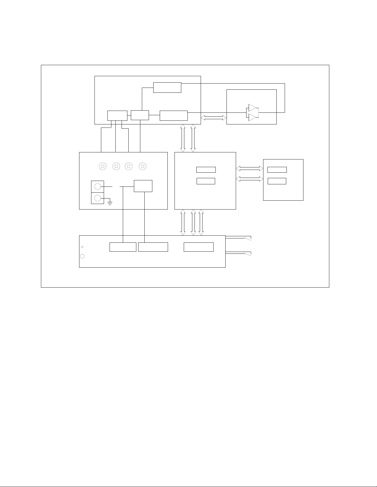
Refer to the Block Diagram in the
“Specifications” section for the following
discussion. Receive signals are routed
through the antenna connector to the antenna
relays to the T/R relays switching on the
lowpass filter board to the Radio connector.
Transmit signals are applied to the Radio
connector and routed to the T/R relays on the
Lowpass filter board and then to the input
attenuator, input power bridge and frequency
counter. This signal is applied to the 100 watt
MOSFET amplifier and back to the lowpass
filter to be applied to the correct filter and on
418 Users manual Release 1.00 – NOVEMBER, 2011
Part #74468
Printed in USA 4
Page 5
to the antenna relays, then to the antenna
connector.
The PIC processor in the CPU module
executes firmware to perform functions such
as check input power and frequency, enable
bias to the MOSFET amplifier, checking
SWR, current, output power and temperature
based on the inputs from the front panel
buttons, key in jack or data from the ACC 1
connector.
Cooling is achieved with the two internal fans
that are controlled by the CPU that is
monitoring the temperature of the MOSFET
heat sink.
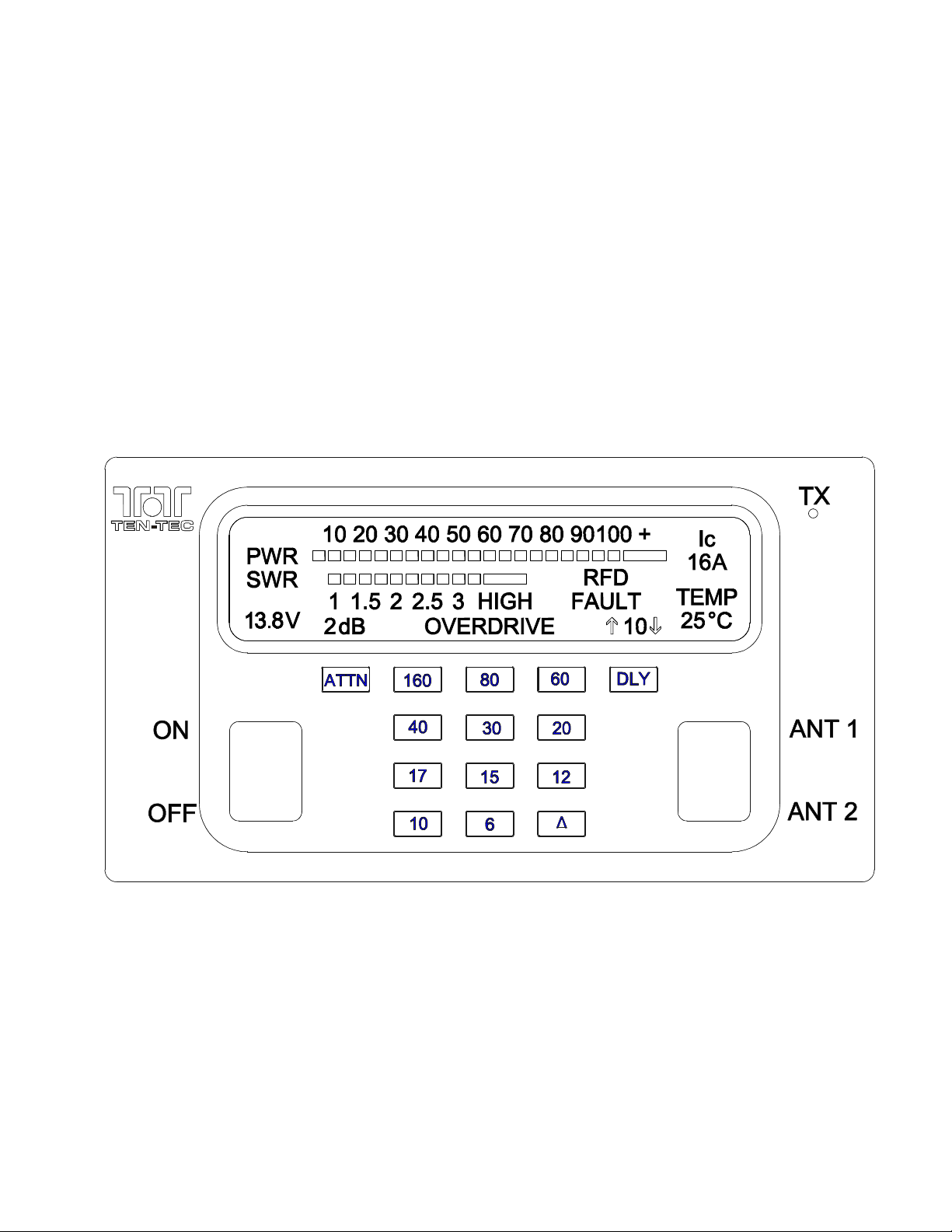
Figure 2.1 418 Front Panel
418 Users manual Release 1.00 – NOVEMBER, 2011
Part #74468
Printed in USA 5
Page 6

2. 418 FRONT PANEL
This section of your 418 Manual will discuss
the front panel operations and adjustments.
2.1. SWITCHES
On Off power switch
Used to turn on the amplifier. When in the off
amplifier is in bypass mode. If a fault occurs
the power switch must be cycled to clear
fault.
Ant 1 Ant 2
This switch selects either Antenna 1 or
Antenna 2. The 6 Meter antenna is always
selected when the amplifier is on 6 Meters
2.2. Band Buttons
Are for manual selection of one of the 11
bands. In automatic or manual mode the
amplifier will light the button of the band
selected.
2.3. Attenuator Button
This button is used to reduce the input power
to the amplifier when 5 watts or less can not
be supplied. When selected the button will
light and will show either 0,2,4 or 6 db of
attenuation on the display directly above the
button. To determine the value of attenuation,
this formula can be used.
Input power x db multiplier = 5 watts.
db multiplier
2 .625
4 .400
6 .250
Example RF = 20 watts attenuator = 6 db
20 x .250 = 5 watts
The ATTENUATOR button can used to
lower the output power of the 418 when less
than 100 watt output is desired.
2.4. Delay Button
The delay button delays the transmit to
receive transition to keep the amplifier in
transmit mode. The amount of delay can be
seen directly above the button on the display.
Each press of the DLY button will increase
the delay. To decrease delay press and hold
DLY button for 3 seconds. The up arrow will
turn off and the down arrow will turn on.
Each press of the DLY button will decrease
the delay.
2.5. Delta Button
When the delta button is pressed and lit the
amplifier looks for data coming in on the
ACC 1 connector. If there is no data the
amplifier will use the internal frequency
counter to select the band of operation. To
use the internal frequency counter. Key
amplifier with at least 200milliwatts input and
release the key and the 418 will select the
band of operation.
2.6. Leds
The TX led will light to show when the
amplifier is in transmit mode. Another led
mounted in the logo will light when the
output power reaches approximately 80 watts.
2.7. Display
Visible on the display is a 10 to 100 watt bar
graph for forward power, and a 1 to 3 SWR
bar graph. Ic is Also shown. This is the
current of the mosfet finals, and TEMP,
which is the temperature of the heat sink. Not
always seen are the words OVERDRIVE,
RFD, and FAULT. More on this in section 5.
2.8. Backlight
The lcd has 6 leds to back light the display.
2 red 2 blue 2 green. To backlight
adjustment, press and hold 80 Meter button
on turn on. Pressing the 160 Meter button will
increase the red intensity, pressing the 40
Meter button will decrease the red intensity.
Pressing the 80 Meter button will increase the
blue intensity, and pressing the 30 Meter will
decrease the blue intensity. Pressing the 60
Meter button will increase the green intensity,
and pressing the 20 Meter button will
decrease the green intensity. Pressing the 15
Meter button will increase the overall
brightness of the display, and pressing the 6
Meter button will decrease the overall
brightness. Cycling the power switch will set
the amplifier to normal operation and save
backlight settings.
418 Users manual Release 1.00 – NOVEMBER, 2011
Part #74468
Printed in USA 6
Page 7
AMP KEY
3. 418 Rear Panel
3.1. ACC 1
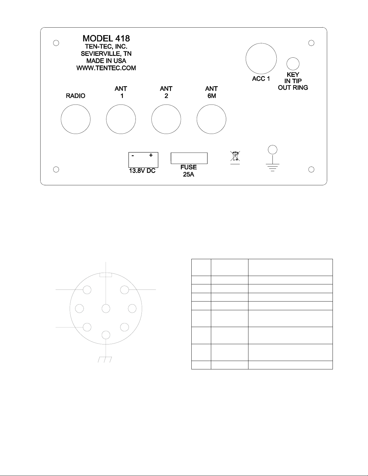
The Eagle is equipped with an 8 pin
accessory connector. Refer to following
figure for the pin definitions as viewed from
the rear of the amplifier.
7
CLK
3
5
8
2
Figure 3-2 ACC1 Pin out
The pin out and function are listed in the
following table.
6
1
4
ENADATA
Pin Name /
Usage
Direction
1 Not used
2 Ground Grounding
3 Not used
4 Not used
5 Clock /
Input
6 Enable /
Input
7 Data /
8 Amp Key Used to key the Amplifier.
Input
Future Use (Do NOT
connect to this pin)
Future Use (Do NOT
connect to this pin)
Future Use (Do NOT
connect to this pin)
Table 3-1 ACC1 Pin out
418 Users manual Release 1.00 – NOVEMBER, 2011
Part #74468
Printed in USA 7
Page 8
3.2. Key In / Out
KEY IN
KEY OUT
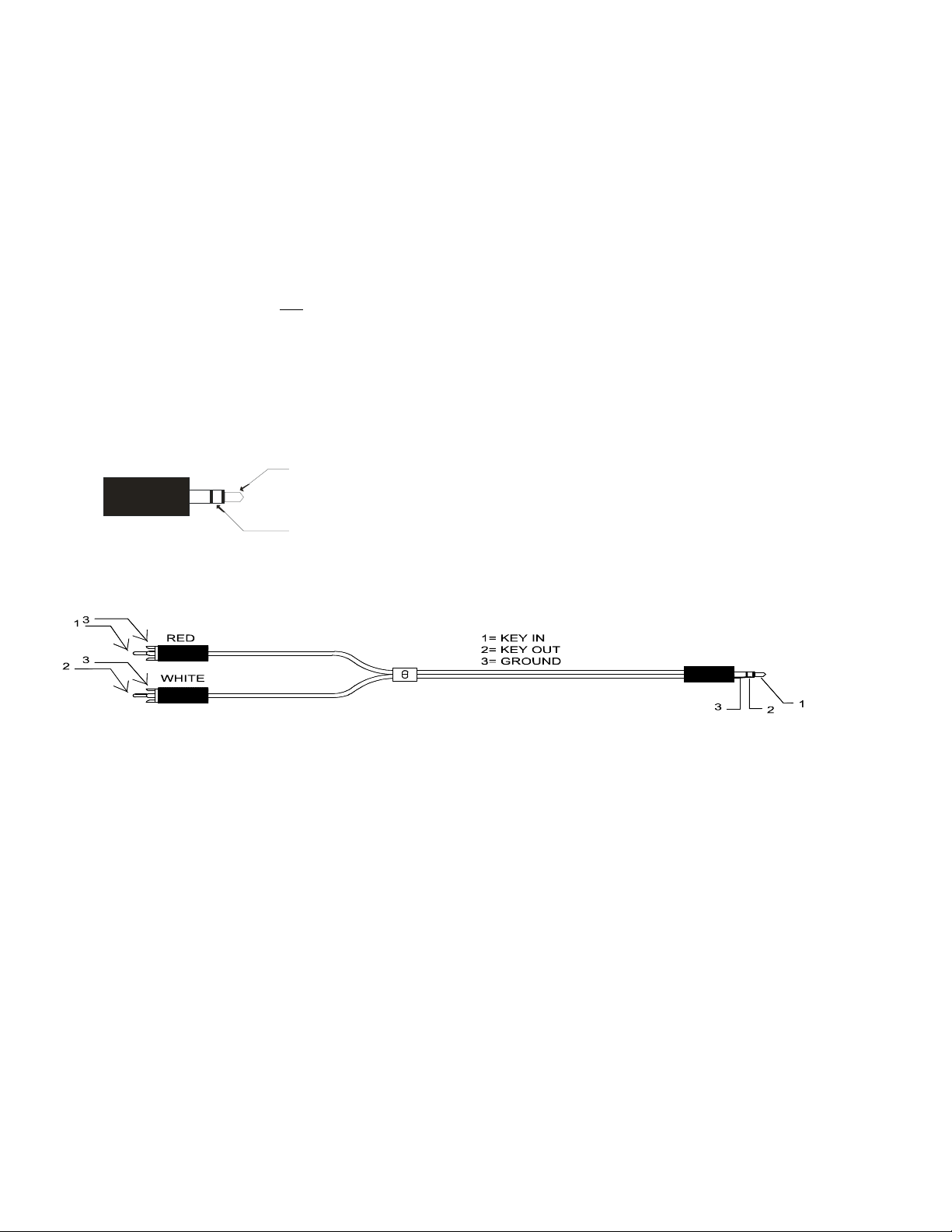
The rear panel on the 418 has a 1/8” stereo
jack for connection of a key input and key
output. The tip is used as the key input to key
the 418 and the ring is used as a key out for
other configurations. The key out has a delay
of 10 msec. This allows the 418’s relay to
close before the transceiver applies RF to the
418. The key out is not a relay. It is a
transistor switch rated for a maximum of 24
volts and 250 mA.
See Figure 2.3-1 for proper wiring. See
section 4 for other connections.
1/8” stereo jack, part number 35263
1/8” stereo to 2 RCA jack, part number 46216
Figure 2.3-1
3.5. Antennas
There are 4 SO239’s on the rear of the 418.
The 1st labeled RADIO is the RF input from
the transceiver. HF ANT 1 and HF ANT 2 are
the HF antenna connections selectable from
the front panel switch. 6M ANT is always
selected when 6 Meters is selected on the
front panel.
3.3. Power
Anderson Power Pole connectors are used for
the 13.8VDC nominal +/- 15% input. These
connectors are rated for 30 Amps each. The
voltage source must be capable of supplying
23 amperes continuous duty
3.4. Fuse
The fuse is an auto style 25amp.
418 Users manual Release 1.00 – NOVEMBER, 2011
Part #74468
Printed in USA 8
Page 9
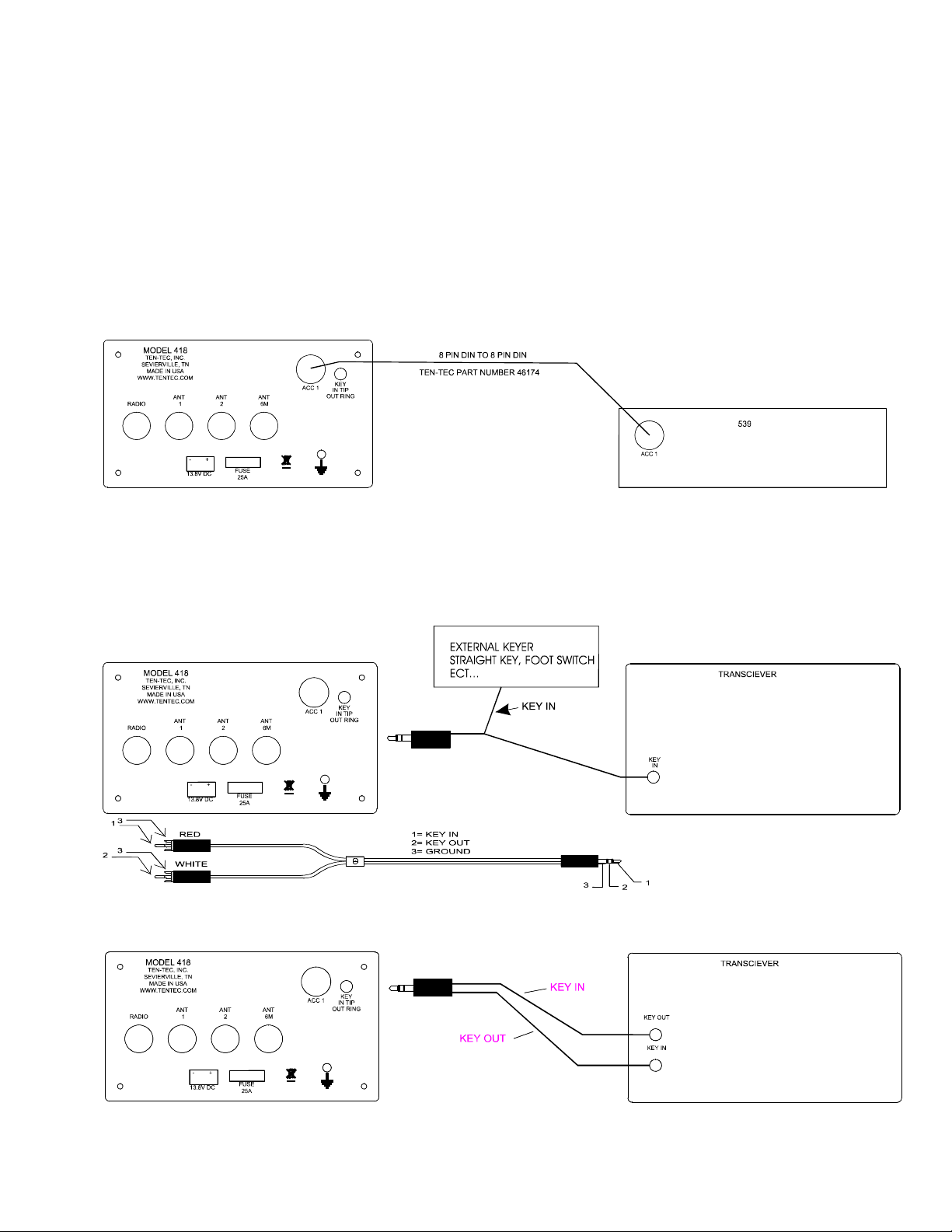
4. Amplifier Hookup
4.1. 418 to 539
The 418 can be interfaced to the 539 using
only the 8 pin din cable. The 539 will control
band changes and keying the amplifiler
4.2. 418 to other
The 1/8” key jack provides a key input on the
tip and a key output on the ring to allow the
418 to key other transceiver. Some methods
are shown below.
Cable number 46216
418 Users manual Release 1.00 – NOVEMBER, 2011
Part #74468
Printed in USA 9
Page 10
418 Users manual Release 1.00 – NOVEMBER, 2011
Part #74468
Printed in USA 10
Page 11

5. Fault
5.1. Fault conditions
When a fault condition occurs the 418 will go
into bypass mode and display the word
FAULT and what the problem was on the
display. To recover from a fault condition,
correct the problem and cycle the power
switch on the 418.
5.2. List of faults
DISPLAY Condition
FAULT Ic >30 amps
FAULT TEMP > 85 degree C
FAULT OVERDRIVE >10 watt in
FAULT OVERDRIVE PWR >115 watts out
FAULT SWR HIGH >3.5:1 swr
FAULT RFD Rf detected not the
same as band
selected.
418 Users manual Release 1.00 – NOVEMBER, 2011
Part #74468
Printed in USA 11
Page 12

6. Specifications
Key Jack: 1/8 “ Stereo
Tip-Key in
Ring- Key out
ACC Din Connector: 8 PIN DIN
Connector – Aux
Key,Clock/Data/
Enable, Ground
DC Power Connector: Power Poles
Fuse: Automotive
Blade Style
Fuse, 25 Amp
32V
Frequency Range: 160-6 meters.
Specifications
apply within
Amateur Radio
bands only.
Antenna Impedance: 50 ohms
nominal.
Antenna Connectors: 4 x SO-239
Supply Voltage Range: 13.8V +/-15%
Operating Temp. Range: 0-50 degrees
Celsius
Dimensions (HxWxD): 3.625” x 6.5” x
7.6”
(excluding feet
and connectors)
Weight: 5.4 lbs
Construction: Molded plastic
bezel, aluminum
chassis, front
and rear panels
and texture
painted steel
covers
Display: Custom FSTN
monochrome
LCD
Display Backlight: 6 LEDS
RF Power Output: 100 W, +/- 1 dB
CW & SSB Duty Cycle: continuous
service @ 100W
AM,FM,AFSK,PSK Duty Cycle: continuous
service @100W,
50% duty cycle
(Tx/Rx)
Cooling: 2 internal fans
temperature
controlled
Harmonic & Spurious Outputs:
<-50dBc @100 W <30MHz;
<-60dB >30MHz
Current Drain: transmit 17 amps
Third Order Intermod: 30dB below peak
All measurements are typical. Results will
vary based on different Test Environment,
Tools, and Test Methods. Specifications are
subject to change.
418 Users manual Release 1.00 – NOVEMBER, 2011
Part #74468
Printed in USA 12
Page 13
7. Block Diagram
POWER
AMPLIFIER
REGULATORS
POWER SWITCH
ANTENNA SWITCH
PIC
C(DISPLAY)
CLK,DAT,ENA(KEYPAD)
C
L
K
,
D
A
T
,
E
N
A
REAR PANEL
13.8VDC
KEY
IN/OUT
1/8" JACK
ACC 1
8 PIN DIN
LOWPASS FILTER
ANTENNA
RELAYS
ANT6 ANT2 ANT1 RADIO
+
-
I/O
5V,3.3V
LOW PASS
FILTERS
T/R
RELAYS
POWER
RELAY
POWER RELAY FAN CONTROL
CONTROL
ATTENUATOR
CPU
KEY IN,KE Y OUT
TEMP,Ic,ENA
EEPROM
PWR RLY CON TROL
FAN CONTRO L
TEMP,Ic,ENA
2
I
FRONT PANEL
DISPLAY
KEY PAD
418 Users manual Release 1.00 – NOVEMBER, 2011
Part #74468
Printed in USA 13
Page 14

8. In Case of Difficulty
While we cannot cover every possible
problem, here are some hints for dealing with
some potential difficulties. Check the
obvious. Is your dc power source okay?
Check power supply, cable and connector(s).
Is the 25 ampere fuse loose or missing?
Antenna problems? Try a dummy load. Is a
proper antenna connected? Is any
external antenna switch connected and
properly set?
Problem: Distorted SSB transmit – or –
Perceived RFI in the shack.
The ALC LED should flash on voice peaks,
but not remain continuously lit in SSB modes.
A frequent cause of a distorted SSB signal is
inadequate RF grounding resulting in RF
feedback. Common RF grounding problems
are no ground connection, or too long a lead
to a good ground. Many problems relate to
the lack of an RF station ground, as
contrasted with a safety ground connection.
We recommend bonding all equipment
chassis together with short heavy metal braid
or strap. Make these connections from
chassis ground lug to chassis ground lug and
connect the last piece in the chain feeding the
antenna to a good earth ground. This lead
needs to be as short as possible. Lengths near
¼ wavelength on any band used can be
particularly troublesome when the far end is
connected to earth. It is very important that
the external power supply and the transceiver
and all equipment with grounding lugs are
properly grounded.
Another potential cause of distorted SSB
arises when the station is in the near field of
the antenna. This is a problem many
apartment dwellers face.
RF can also be induced on any unshielded
wires.
Problem: 418 power shuts off while
transmitting
The 418 is equipped with a silicon-controlled
rectifier that opens if the PA current draw
exceeds an instantaneous power of
approximately 30 amps. This will shut off
power to the mosfet finals. Excessive current
draw can indicate a problem with excessive
SWR due to antenna or feedline problems.
Power to the 418 can be restored by cycling
the power switch off and on or the 13.8 Vdc
source off and on.
If the above do not solve your problem,
please consult with our service department
(865) 428-0364 or service@tentec.com
9. Warranty & Return Policy
Warranty policy for Ten-Tec products is
covered in the gold color page located on the
last page of this manual.
FOR EQUIPMENT MANUFACTURED BY
TEN-TEC: TEN-TEC factory built radio
equipment is sold under a 30-day risk-free
trial period. Any piece of equipment
manufactured by TEN-TEC may be returned,
undamaged, within 30 days of purchase for a
full purchase price refund, less shipping
charges (customer pays shipping both ways).
If you want to return a piece of equipment
purchased from TEN-TEC, please call the
sales department at (865) 453-7172 from 8
a.m. to 5 p.m. Eastern time, Mon-Fri and
obtain a return merchandise authorization
number. Calling in advance for an RMA
number allows us to quickly process your
return and refund once your item arrives.
Ship return items with letter enclosed inside
the box noting the RMA number and your
name, address, and telephone number.
Return items are shipped to
TEN-TEC INC, 1185 Dolly Parton Pkwy,
Sevierville, TN 37862 USA.
418 Users manual Release 1.00 – NOVEMBER, 2011
Part #74468
Printed in USA 14
Page 15

FCC Compliance
Note: This equipment has been tested and
found to comply with the limits for a Class B
digital device, pursuant to part 15 of the FCC
Rules. These limits are designed to provide
reasonable protection against harmful
interference in a residential installation. This
equipment generates, uses and can radiate
radio frequency energy and, if not installed
and used in accordance with the instructions,
may cause harmful interference to radio
communications. However, there is no
guarantee that interference will not occur in a
particular installation. If this equipment does
cause harmful interference to radio or
television reception, which can be determined
by turning the equipment off and on, the user
is encouraged to try to correct the interference
by one or more of the following measures:
• Reorient or relocate the receiving antenna.
• Increase the separation between the
equipment and receiver.
• Connect the equipment into an outlet on a
circuit different from that to which the
receiver is connected.
• Consult TEN-TEC service for technical
assistance (865) 428-0364
418 Users manual Release 1.00 – NOVEMBER, 2011
Part #74468
Printed in USA 15
 Loading...