


5100

ENGLISH - ESPAÑOL - FRANÇAIS
5100
Battery Automatic Scrubber
Fregadora Automática Batería
Balayeuse Automatique De Batterie
Operator and Parts Manual
Manual De Operador
Y Lista De Repuestos
Model Part No.:
609139
609140 - Pac
SM15029
Opérateur Manuel et
Liste Des Piéces
www.tennantco.com
609372
Rev. 04 (04-2007)
*609372*

OPERATION
This manual is furnished with each new model.
It provides necessary operation and maintenance
instructions and an illustrated parts list.
Read this manual completely and understand the
machine before operating or servicing it.
When ordering replacement parts, use the illustrated
parts lists section in this manual. Before ordering parts
or supplies, be sure to have your machine model
number and serial number available. Parts and
supplies may be ordered by phone or mail from any
authorized parts and service center, distributor or from
any of the manufacturer’s subsidiaries.
This machine will provide excellent service. However,
the best results will be obtained at minimum costs if:
S The machine is operated with reasonable care.
S The machine is maintained regularly - per the
machine maintenance instructions provided.
S The machine is maintained with manufacturer
supplied or equivalent parts.
MACHINE DATA
Please fill out at time of installation for future reference.
Model No.-
Install. Date -
Serial No.-
PROTECT THE ENVIRONMENT
Please dispose of packaging materials,
old machine components such as
batteries, hazardous fluids such as
antifreeze and oil, in a safe
environmentally way according to your
local waste disposal regulations.
Always remember to recycle.
Tennant Company
PO Box 1452
Minneapolis, MN 55440
Phone: (800) 553--8033 or (763) 513--2850
www.nobles.com
Nobles, the Nobles logo and the Speed Scrub logo are registered United
States trademarks of Tennant Company.
Specifications and parts are subject to change without notice.
Copyright E1999, 2000, 2005, 2007 Tennant Company. All rights reserved.
Printed in U.S.A.
2
Speed Scrub 1701 Plus (04--07)

TABL E OF CONTENTS (ESPAÑOL....23) (FRANÇAIS....45)
OPERATION
SAFETY PRECAUTIONS 4....................
SAFETY LABELS 5...........................
MACHINE COMPONENTS 6...................
CONTROL PANEL SYMBOLS 6...............
MACHINE INSTALLATION 7...................
UNCRATING MACHINE 7..................
INSTALLING BATTERIES 7................
MACHINE SETUP 8..........................
ATTACHING SQUEEGEE ASSEMBLY 8.....
INSTALLING PAD DRIVER OR BRUSH 9....
REMOVING PAD DRIVER OR BRUSH 10.....
FILLING SOLUTION TANK 10...............
ADJUSTING CONTROL HANDLE HEIGHT 11.
MACHINE OPERATION 11.....................
PRE--OPERATION CHECKS 11..............
OPERATING MACHINE 1 1..................
OPERATING ES (OPTION) 12...............
WHILE OPERATING MACHINE 12...........
OPERATING ACCESSORY TOOLS
(OPTIONAL) 13............................
CIRCUIT BREAKERS 13....................
MACHINE ADJUSTMENTS 13..................
ADJUSTING SOLUTION FLOW 13...........
ADJUSTING PAD PRESSURE 14............
ADJUSTING SQUEEGEE LIFT CABLE 14....
DRAINING TANKS 14..........................
DRAINING RECOVERY TANK 14............
DRAINING SOLUTION TANK 15.............
BA TTER Y CHARGING 15......................
MACHINE MAINTENANCE 16..................
DAILY MAINTENANCE 16...................
WEEKLY MAINTENANCE 16................
MONTHLY MAINTENANCE 17...............
QUARTERLY MAINTENANCE 17............
BATTERY MAINTENANCE 17...............
TRANSPORTING MACHINE 18.................
STORING MACHINE 18........................
RECOMMENDED STOCK ITEMS 18.............
TROUBLE SHOOTING 19......................
SPECIFICATIONS 21..........................
MACHINE DIMENSIONS 22....................
ELECTRICAL DIAGRAMS 68...................
PARTS LIST 70...............................
REPLACEMENT BRUSHES AND PAD
DRIVER GROUP 70........................
SOLUTION TANK GROUP 72................
RECOVERY TANK GROUP 74...............
WHEEL GROUP 76........................
SCRUB HEAD GROUP 78..................
PLUMBING GROUP 80.....................
VACUUM MOTOR GROUP 82...............
SQUEEGEE GROUP 84
CONTROL HANDLE GROUP 86.............
CONTROL CONSOLE GROUP 87...........
BATTERY AND CHARGER GROUP 88.......
OPTIONS 90..................................
ES (EXTENDED SCRUB) KIT 90.............
WAND PUMP KIT 92.......................
HOUR METER AND LOW VOLTAGE
INTERRUPTER KITS 94....................
WET PICK--UP TOOL KIT 95................
DELUXE POWER WAND GROUP 96.........
POWER WAND GROUP 98.................
POWER WAND HOSE GROUP 100...........
QUICK CHANGE BATTERY KIT 77...........
BATTERY CONNECTOR MOUNT KIT 78.....
....................
Speed Scrub 1701 Plus (04--07)
3

OPERATION
SAFETY PRECAUTIONS
The following information signals potentially
dangerous conditions to the operator or
equipment:
This machine is intended for commercial use. It is
designed exclusively to scrub hard floors in an
indoor environment and is not constructed for any
other use. Use only recommended pads, brushes
and commercially approved floor cleaners
intended for machine application.
All operators must read, understand and practice
the following safety precautions.
The following warning alert symbol and the “FOR
SAFETY” heading are used throughout this manual as
indicated in their description:
WARNING: To warn of hazards or unsafe
practices which could result in severe personal
injury or death.
FOR SAFETY: To identify actions which must be
followed for safe operation of equipment.
Failure to follow these warnings may result in
personal injury, electrical shock, fire or explosion.
WARNING: Fire Or Explosion Hazard:
-- Never Use Flammable Liquids Or Operate
Machine in Or Near Flammable Liquids,
Vapors Or Combustible Dusts.
This machine is not equipped with explosion proof
motors. The electric motors will spark upon start
up and during operation which could cause a flash
fire or explosion if machine is used in an area
where flammable vapors/liquids or combustible
dusts are present.
-- Do Not Pick Up Flammable Materials Or
Reactive Metals.
-- Batteries Emit Hydrogen Gas. Keep Sparks
And Open Flame Away. Keep Battery
Compartment Open When Charging.
WARNING: Electrical Shock Hazard.
Disconnect Battery Cables Before Servicing
Machine.
WARNING: Spinning Brush. Keep Hands
Away. Turn Off Power Before Working On
Machine.
FOR SAFETY:
1. Do not operate machine:
-- With flammable liquids or near flammable
vapors as an explosion or flash fire may
occur.
-- Unless trained and authorized.
-- Unless operator manual is read and
understood.
-- If not in proper operating condition.
2. Before operating machine:
-- Make sure all safety devices are in place
and operate properly.
3. When using machine:
-- Go slow on inclines and slippery surfaces.
-- Wear non--slip shoes.
-- Reduce speed when turning.
-- Report machine damage or faulty
operation immediately.
-- Never allow children to play on or around.
-- Follow mixing and handling instructions
on chemical containers.
4. Before leaving or servicing machine:
-- Stop on level surface.
-- Turn machine off.
5. When servicing machine:
-- Avoid moving parts. Do not wear loose
jackets, shirts, or sleeves.
-- Disconnect battery connections before
working on machine.
-- Wear protective gloves and eye protection
when handling batteries or battery cables.
-- Avoid contact with battery acid.
-- Do not power spray or hose off machine.
Electrical malfunction may occur.
-- Use manufacturer supplied or approved
replacement parts.
-- All repairs must be performed by a
qualified service person.
-- Do not modify the machine from its
original design.
4
Speed Scrub 1701 Plus (06--05)

OPERATION
6. When transporting machine:
-- Turn machine off.
-- Do not lift machine when batteries are
installed.
-- Get assistance when lifting machine.
-- Use a recommended ramp when
loading/unloading on/off truck or trailer.
-- Use tie--down straps to secure machine to
truck or trailer.
-- Put scrub head in the lowered position.
SAFETY LABELS
The safety label appears on the machine in the location indicated. Replace label if it is missing or becomes damaged
or illegible.
WARNING LABEL -- LOCATED ON THE RECOVERY TANK COVER.
Speed Scrub 1701 Plus (04--07)
5

OPERATION
MACHINE COMPONENTS
2
7
6
5
4
1
3
17
18
22
38
21
23
25
8
9
16
24
26
13
10
1415
20
19
27
31
32
33
11
29
30
36
34
28
12
37
35
1. Key Switch
2. Power ON/OFF Indicator Light
3. Hour Meter (Opt.)
4. Main Circuit Breaker
5. Brush Circuit Breaker
6. Brush Release Button
7. Brush Pressure Meter
8. Battery Meter
9. Vacuum ON/OFF Switch
10. Solution ON/OFF Switch
11. Squeegee Lift Knob
12. Control Handle
13. Control Handle Height
Adjustment Knobs
CONTROL PANEL SYMBOLS
Main Power
Indicator Light
Key Switch
Vacuum
Switch
Solution
Switch
14. Wand Kit ON/OFF Switch (Opt.)
15. ES ON/OFF Switch (ES Model)
16. Pump On Light (ES Model)
17. Charger Plug
18. Recovery Tank Drain Hose
19. Solution Tank Drain Hose With
Level Indicator
20. Solution Fill Port Cover
21. Scrub Head Lift Pedal
22. Scrub Head Release Lift Pedal
23. Solution Flow Adjustment Knob
24. Squeegee Vacuum Hose
25. Squeegee Assembly
26. Squeegee Thumb Knobs
27. Wall Rollers
Brush Motor
35A Circuit Breaker
Main Power
20A Circuit Breaker
28. Brush Trigger
29. Recovery Tank Lid
30. Recovery Tank
31. Battery Compartment Hood
32. Scrub Head
33. Scrub Head Skirt
34. Transport Caster
35. Main Wheels
36. Wand Kit Solution Hose
Coupler (Opt.)
37. Solution Tank
38. Pad Pressure
Adjustment Knob
Battery Charge
Meter
Read Manual
Before Operating
6
Speed Scrubt 1701 (02--04)

MACHINE INSTALLATION
OPERATION
Squeegee assembly is packaged with machine.
Batteries, battery charger, brush, pad driver and pads
must be purchased separately. Consult an authorized
distributor for specific pads and brushes.
UNCRA TING MACHINE
Carefully check carton for signs of damage. Report
any damage at once to carrier.
Check Machine Contents to ensure package is
complete. Contact distributor for missing items.
Machine Contents:
1 -- Battery Cable #602871
1 -- Wire Asm. #6X24” Black #603208
2 -- 12VDC 130AH Batteries #130869 (included with
machine PAC)
1 -- Battery Charger, 24V/15A 120V #603553 (included
with machine PAC)
To uncrate your machine, remove shipping straps and
carefully lift or make a ramp to remove machine from
pallet. Do not roll machine off pallet, damage may
result.
FOR SAFETY: Get assistance when lifting
machine. Do not lift machine when batteries are
installed.
Raise scrub head to transport position before
maneuvering machine. Step down firmly on scrub
head lift pedal to raise (Figure 1).
NOTE: To prevent scrub head skirt damage, always
keep machine in transport position when pad driver is
not installed.
ATTENTION: The use of supplies other than those
recommended by manufacturer may cause
damage.
INSTALLING BATTERIES
WARNING: Fire Or Explosion Hazard.
Batteries Emit Hydrogen Gas. Keep Sparks And
Open Flame Away. Keep Battery Compartment
Open When Charging.
FOR SAFETY: When servicing machine, wear
protective gloves and eye protection when
handling batteries or battery cables. Avoid contact
with battery acid.
Battery Specifications:
Two 12 volt, deep cycle batteries. Consult with an
Authorized Distributor for specific batteries. Maximum
battery dimensions are 178mm (7 in.) W x 330mm
(13 in.) L x 254mm (10 in.) H.
1. Park machine on a level surface, turn off all
switches, and remove key.
2. Remove battery hood to access battery
compartment. Then remove metal battery tray and
loose battery cable from compartment.
3. Disconnect vacuum hose from recovery tank
snout. Carefully install bottom battery into
compartment with battery posts positioned
towards rear of machine (Figure 2).
FIG. 1
ATTENTION: Do not roll machine off pallet,
damage may occur.
A TTENTION: To prevent possible machine
damage, install batteries AFTER removing
machine from shipping pallet.
Speed Scrub 1701 Plus (04--07)
FIG. 2
ATTENTION: Do not drop battery into
compartment, battery and machine housing
damage may result. This damage is not covered
by warranty.
4. Connect red battery cable coming from machine to
positive (+) post of bottom battery. Then connect
black jumper cable to negative (--) post (Figure 4).
7

OPERATION
5. After connecting cables to bottom battery, carefully
hang metal battery tray on studs located above
bottom battery. Place top battery into tray with
posts positioned towards rear of machine. Secure
top battery with strap (Figure 3).
FIG. 3
6. Connect black battery cable coming from machine
to negative (--) post of top battery. Then connect
opposite end of black jumper cable to positive (+)
post (Figure 4).
(--)
Black
Cable
(+)
Jumper
Cable
TOP
BATTERY
8. After batteries are properly installed, turn on key
and vacuum switch and check battery meter
charge level. Charge if necessary (See BATTERY
CHARGING) (Figure 6).
FIG. 6
MACHINE SETUP
ATTACHING SQUEEGEE ASSEMBLY
1. Turn key to the off position.
FOR SAFETY: Before leaving or servicing
machine, stop on level surface and turn off
machine.
(--)
Jumper
Cable
FIG. 4
(+)
Red Cable
BOTTOM
BATTERY
7. Reconnect vacuum hose to recovery tank snout
as shown (Figure 5).
FIG. 5
2. Raise squeegee mount bracket by moving
squeegee lift knob to the left (Figure 7).
FIG. 7
3. Loosen two thumb knobs on squeegee assembly
and slide squeegee into slots on squeegee mount
bracket (Figure 8).
8
Speed Scrub 1701 Plus (02--04)

3. Turn key switch on (Figure 11).
OPERATION
FIG. 8
4. Tighten thumb knobs securely.
5. Connect vacuum hose from machine to squeegee
assembly (Figure 9).
FIG. 9
INSTALLING PAD DRIVER OR BRUSH
1. Select a recommended pad or brush that best
meets your cleaning needs.
NOTE: Consult an authorized distributor for
pad/brush recommendations.
2. Attach pad to pad driver before mounting driver to
motor hub. Secure pad with plastic centerlock ring
(Figure 10).
FIG. 11
4. Place the pad driver/brush on the floor in front of
the scrub head (Figure 12).
FIG. 12
5. Tilt the machine back on it’s rear wheels and
center the scrub head down over the pad
driver/brush (Figure 12).
6. IMPORTANT STEP: Release the brush lift pedal
from the transport position (Figure 13). Align the
motor hub down inside the pad driver/brush.
FIG. 10
Speed Scrub 1701 Plus (02--04)
FIG. 13
7. Pull the triggers to engage the pad driver/brush.
Make sure the front wheel is in the UP position
(Figure 14).
NOTE: When a pad driver/brush is not installed, make
sure to keep the machine in transport position to
prevent skirt damage.
9

OPERATION
FIG. 14
NOTE: Before installing pad driver or brush make sure
mounting surface is clean. A clean surface will ease
pad driver removal later.
REMOVING PAD DRIVER OR BRUSH
1. Raise scrub head to transport position. Step down
firmly on scrub head lift pedal to raise (Figure 15).
NOTE: To prevent scrub head skirt damage, always
keep machine in transport position when pad driver or
brush is not installed.
FILLING SOLUTION TANK
1. Transport machine to filling station. Raise
squeegee and scrub head when transporting.
2. Turn off key switch.
3. Remove solution tank fill port cover.
4. Fill solution tank with 28L (7.5 gal) of clean water,
60°C (140°F) maximum temperature. To fill with
bucket, use a bucket with a spout (Figure 17).
FIG. 15
2. Turn key switch on.
3. Tilt machine back on it’s rear wheels.
4. While pressing the “brush release button”, pull and
release the brush trigger quickly. The pad
driver/brush will automatically spin off motor hub.
If it doesn’t release, repeat step (Figure 16).
FIG. 16
FIG. 17
NOTE: If filling with a bucket be certain that bucket is
clean. This will prevent possible solution line clogs.
5. Add cleaning chemical. See proper dilution ratio
instructions on chemical container.
6. Replace solution tank fill port cover.
FOR SAFETY: When using machine, follow mixing
and handling instructions on chemical containers.
ATTENTION: Use only recommended detergents.
Machine damage due to improper detergent usage
will void the manufacturer’s warranty. Contact
your Sales Representative for detergent
recommendations.
WARNING: Fire Or Explosion Hazard. Never
Use Flammable Liquids Or Operate Machine in Or
Near Flammable Liquids, Vapors Or Combustible
Dusts.
7. If machine is equipped with ES (Extended Scrub)
Option, the recovery tank can be partially filled to
extend scrub time.
a. Remove recovery tank lid and fill tank with 13L
(3.5 gal) of clean water, 60°C (140°F)
maximum temperature. Close lid.
b. Make sure ES switch is turned on when
operating machine (Figure 18).
10
Speed Scrub 1701 Plus (02--04)

FIG. 18
c. The ES light will glow when the ES pump is
recycling.
ADJUSTING CONTROL HANDLE HEIGHT
The control handle has three height settings to
accommodate a comfortable operating height.
1. Locate two control handle height adjustments
knobs on handle (Figure 19).
2. Pull both knobs and raise or lower handle, release
knobs to lock (Figure 19).
OPERATION
S Check condition of squeegee blades.
OPERATING MACHINE
1. Release brush lift pedal from transport position by
stepping down on scrub head release pedal
(Figure 20).
FIG. 20
2. Lower squeegee assembly by moving squeegee
lift knob to the right (Figure 21).
FIG. 19
MACHINE OPERATION
FOR SAFETY: Do not operate machine unless
operator manual is read and understood.
PRE--OPERA TION CHECKS
S Sweep and dust mop floor to remove particles and
other debris.
S Check battery meter charge level to ensure
batteries are fully charged (See BATTERY
CHARGING).
S Check condition of pad or brush.
Speed Scrub 1701 Plus (06--05)
FIG. 21
FIG. 22
NOTE: The solution flow and brush will not start until
brush triggers are pulled.
4. Pull brush triggers and begin walking with
machine. The brush will propel the machine
forward allowing little effort maneuvering the
machine (Figure 23).
11

OPERATION
FIG. 23
NOTE: On rough surfaces it may be necessary to
reduce brush pressure.
5. Check the brush meter pressure when scrubbing.
Only operate machine in green zone. Never
operate machine in red zone (Figure 24).
NOTE: If brush pressure adjustment is required, see
MACHINE ADJUSTMENTS.
WARNING: Fire Or Explosion Hazard. Never
Use Flammable Liquids Or Operate Machine in Or
Near Flammable Liquids, Vapors Or Combustible
Dusts.
2. Turn on ES switch. During operation the ES pump
will automatically start recycling when ES pump on
light turns on (Figure 25).
FIG. 25
3. When finished scrubbing, drain and rinse solution
tank and clean ES filter (See DRAINING TANKS).
FIG. 24
ATTENTION: Do not operate machine with pad
pressure meter in red zone, circuit breakers will
trip and floor damage may occur.
6. To operate machine in reverse, simply pull the
machine backwards while pulling triggers.
7. To stop scrubbing, release brush triggers, turn off
all switches, and raise scrub head and squeegee.
OPERATING ES (OPTION)
ES Option extends scrubbing time by reusing
recovered water. The recovered water is filtered and
recycled back into the solution tank for reuse.
1. Fill recovery tank with 13L (3.5 gal) when filling
solution tank for operation.
WHILE OPERATING MACHINE
FOR SAFETY: When using machine, go slow on
inclines and slippery surfaces.
1. Observe amount of solution flow on floor. If
solution flow adjustment is needed, see MACHINE
ADJUSTMENTS.
2. Periodically check for foam buildup in recovery
tank (look through clear lid). If excessive foam is
developing, pour a recommended foam control
solution into recovery tank.
ATTENTION: Do not allow foam to enter the float
shut-off screen, vacuum motor damage will result.
Foam will not activate the float shut-off screen.
3. Always operate with caution when scrubbing
around walls or obstacles.
4. If squeegee leaves streaks, raise and wipe blades
with a cloth. Pre-sweep area to prevent streaking.
If squeegee adjustment is necessary, see
MACHINE ADJUSTMENTS.
5. Overlap each pass by 50mm (2 in).
6. Change or turn over pads when dirty.
7. Stay clear of floor obstructions, such as electrical
plates or grates, they will destroy pads.
8. During brief stops, you do not have to turn off any
switches, the brushes and solution flow will
automatically stop when triggers are released.
12
Speed Scrub 1701 Plus (06--05)

9. Periodically check battery meter discharge level.
When needle drops to the red zone, recharge
batteries.
ATTENTION: Do not operate machine with battery
meter in red zone, battery damage will result.
OPERATION
CIRCUIT BREAKERS
The machine is equipped with two circuit breakers to
protect machine from damage. The Main (20amp) and
Brush (35amp) circuit breakers.
WARNING: Fire Or Explosion Hazard. Do Not
Pick Up Flammable Materials Or Reactive Metals.
10. On last scrubbing pass, turn off solution switch
just prior to stopping machine. This will allow total
recovery pick up.
1 1. When solution tank runs dry , drain recovery tank
(See DRAINING TANKS).
OPERATING ACCESSORY TOOLS (OPTIONAL)
1. Attach accessory solution hose to quick coupler.
2. Disconnect squeegee hose from inlet tube and
replace with accessory vacuum hose.
3. Connect hoses to wand.
4. Turn on key, wand pump and vacuum switches
(Figure 26).
If a circuit breakers should trip during operation,
determine cause, allow motor to cool and then
manually reset breaker (See TROUBLE SHOOTING).
Brush motor circuit breakers will trip due to excessive
overload on pad. Reduce pad pressure or replace pad
if breaker trips. Circuit breakers are located on control
console (Figure 27).
FIG. 27
MACHINE ADJUSTMENTS
FIG. 26
5. Operate accessory tool as normal.
WARNING: Fire Or Explosion Hazard. Do Not
Pick Up Flammable Materials Or Reactive Metals.
FOR SAFETY: Before leaving or servicing
machine, stop on level surface and turn off
machine.
ADJUSTING SOLUTION FLOW
To increase or decrease the maximum solution flow,
turn adjustment knob. Adjustment knob is located near
brush lift pedal (Figure 28).
FIG. 28
Speed Scrub 1701 Plus (06--05)
13

OPERATION
ADJUSTING PAD PRESSURE
NOTE: On rough surfaces it may be necessary to
reduce brush pressure.
To adjust pad pressure, turn adjustment knob
clockwise to decrease or counterclockwise to increase
pad pressure. Adjustment knob is located below brush
lift pedal (Figure 29).
FIG. 29
ADJUSTING SQUEEGEE LIFT CABLE
To adjust squeegee lift cable, loosen lock nuts and
turn adjustment stem on squeegee cable. Retighten
lock nuts after adjusting (Figure 30).
DRAINING TANKS
When to drain recovery tank:
-- After each use.
-- Between solution tank fill ups.
-- When solution flow stops during operation.
-- When ball float screen is activated.
-- When squeegee starts trailing water.
NOTE: If using the ES recycling system, be certain to
drain and rinse both tanks after each use.
FOR SAFETY: Before leaving or servicing
machine, stop on level surface and turn off
machine.
DRAINING RECOVERY T ANK
ATTENTION: Do not allow foam to enter the float
shut-off screen, vacuum motor damage will result.
Foam will not activate the float shut-off screen.
1. Push machine to floor drain and turn off all
switches. Remove left side drain hose from holder,
position hose over drain, twist loose, and remove
drain hose cap (Figure 31).
FIG. 30
14
FIG. 31
NOTE: If using a bucket to drain machine, do not use
same bucket for filling solution tank. This will prevent
possible solution line clogs.
2. Open clear recovery tank lid and rinse tank, ball
float screen and ES filter if equipped. Remove and
rinse ball float screen and ES filter if they are
excessively dirty. Replace screen and filter
securely.
3. Replace drain hose cap securely when empty.
Speed Scrub 1701 Plus (06--05)

DRAINING SOLUTION TANK
To drain unused cleaning solution or recycled solution
from solution tank, follow steps below:
1. Remove clear drain hose from hose barb, position
hose over drain (Figure 32).
FIG. 32
2. Rinse out solution tank and solution flow system
with clean water to prevent clogging due to
chemical buildup.
3. Replace drain hose securely on hose barb when
empty.
OPERATION
1. Transport machine to a flat, dry surface in a well-ventilated area for charging.
2. Turn off all switches and key.
FOR SAFETY: Before leaving or servicing
machine, stop on level surface and turn off
machine.
3. Remove battery compartment hood.
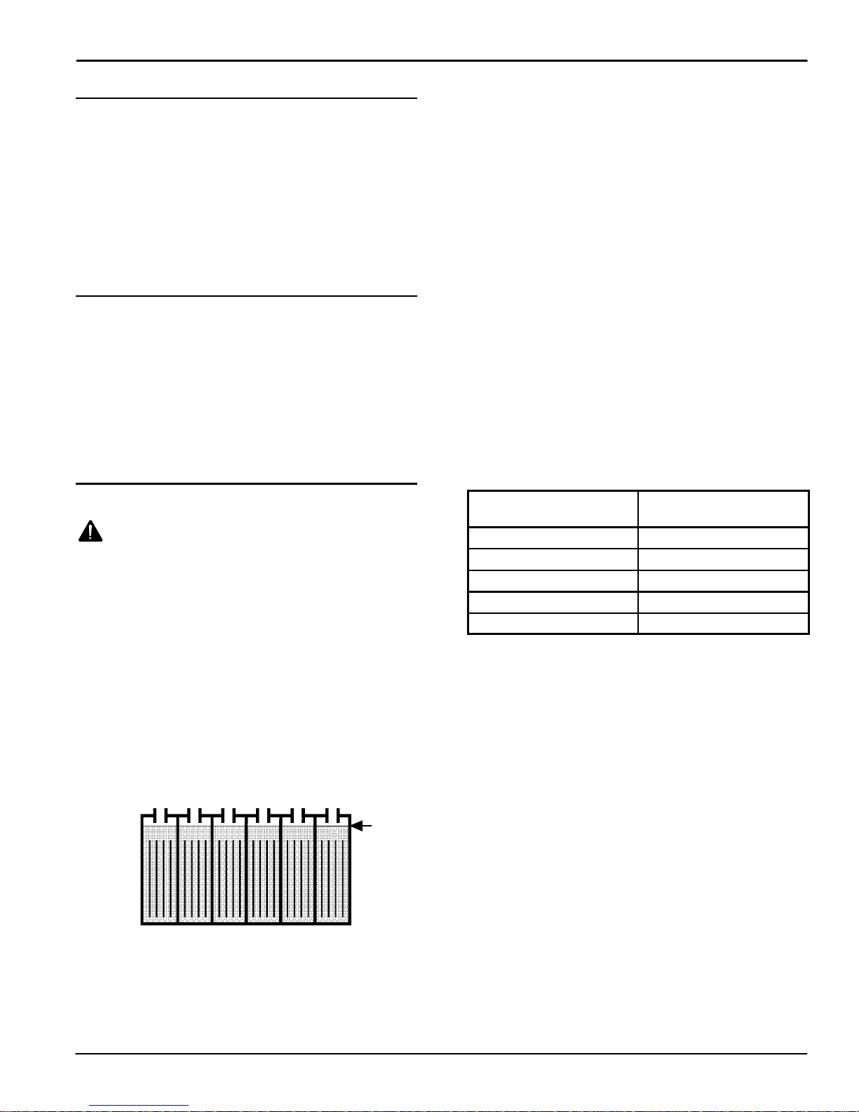
4. Before charging, check the fluid level (A) in each
battery cell. If the battery plates (B) are exposed,
add just enough distilled water to cover plates.
DO NOT OVERFILL. Overfilled batteries can
overflow during charging due to fluid expansion.
Replace cell caps before charging (Figure 33).
B
A
FIG. 33
5. With charger’s power supply cord unplugged,
connect charger to machine (Figure 34).
BATTERY CHARGING
NOTE: Recharge batteries ONLY after a total of 30
minutes of use or more. This will prolong battery life.
The following charging instructions are intended
for the 24V charger supplied with the machine.
Only use a charger with the following
specifications to prevent battery damage.
CHARGER SPECIFICATIONS:
S OUTPUT VOLTAGE - 24 VOLTS
S OUTPUT CURRENT - 25 AMPS MAXIMUM
S AUTOMATIC SHUTOFF CIRCUIT
S FOR DEEP CYCLE BATTERY CHARGING
NOTE: For optimum machine operation, keep
batteries charged at all times. Never let batteries set in
a discharge condition for lengthy periods.
WARNING: Fire Or Explosion Hazard.
Batteries Emit Hydrogen Gas. Keep Sparks And
Open Flame Away. Keep Battery Compartment
Open When Charging.
FOR SAFETY: When servicing machine, wear
protective gloves and eye protection when
handling batteries or battery cables. Avoid contact
with battery acid.
FIG. 34
NOTE: Once charger is connected to machine,
machine becomes inoperable.
6. Plug charger’s power supply cord into a grounded
wall outlet (Figure 35).
Grounded
3HoleOutlet
Ground Pin
FIG. 35
Speed Scrub 1701 Plus (06--05)
15

OPERATION
FOR SAFETY: Do not operate charger unless cord
is properly grounded.
WARNING: Fire Or Explosion Hazard.
Batteries Emit Hydrogen Gas. Keep Sparks And
Open Flame Away. Keep Battery Compartment
Open When Charging.
7. The charger will automatically begin charging and
shut off when fully charged.
8. After charger has turned off, unplug charger from
machine then disconnect charger from wall outlet.
9. After charging, recheck the battery fluid level (A) in
each battery cell. The level should be 1 cm (3/8 in)
from the bottom of sight tubes (B). Add distilled
water if needed. DO NOT OVERFILL (Figure 36).
B
FIG. 36
A
3. Open clear lid, remove and clean the ball float
screen. Replace screen securely (Figure 37).
FIG. 37
4. Open clear lid, remove and clean ES filter, if
equipped. Replace filter securely.
5. Raise squeegee and wipe it off with a dry cloth.
Store squeegee in the up position to prevent
squeegee damage.
6. Clean machine housing with a nonabrasive,
nonsolvent cleaner.
7. Recharge batteries if needed.
MACHINE MAINTENANCE
To keep machine in good working condition, simply
follow the daily, weekly and monthly maintenance
procedures.
FOR SAFETY: When leaving or servicing machine,
stop on level surface and turn off machine.
WARNING: Electrical Shock Hazard.
Disconnect Battery Cables Before Servicing
Machine.
ATTENTION: Contact an Authorized Service
Center for machine repairs. Machine repairs
performed by other than an authorized person will
void your warranty.
NOTE: If equipped with optional hour meter, record
machine hours when service was performed.
DAILY MAINTENANCE
(After Every Use)
1. Remove and clean pad or brush. Never use soiled
pads when cleaning. Replace pad when it
becomes worn or loaded with residue.
2. Drain and rinse both tanks thoroughly .
WEEKLY MAINTENANCE
(Every 20 Hours of Operation)
1. Flush out tanks and solution lines. Pour 750mL
(24 oz) of an acetic acid solution with 11.3L (3 gal)
of hot water into solution tank. Over a floor drain,
activate solution flow briefly to fill solution line.
Shut off power and let machine set over night.
Rinse with clean water afterwards.
2. Remove inline strainer filter and rinse out. Before
removing filter, be certain solution tank is empty.
Filter is located under machine at rear (Figure 38).
FIG. 38
3. Check fluid level in battery cells (See BATTERY
MAINTENANCE).
4. Clean battery tops to prevent corrosion (See
BATTERY MAINTENANCE).
5. Check for loose or corroded battery cables.
16
Speed Scrub 1701 Plus (06--05)
MONTHLY MAINTENANCE
(Every 80 Hours of Operation)
1. Lubricate wheel grease fittings with a water
resistant grease.
2. Lubricate all linkage pivot points with silicone
spray then coat with a water resistant grease to
maintain a smooth operation.
3. Check machine for water leaks and loose nuts and
bolts.
QUARTERLY MAINTENANCE
(Every 250 Hours of Operation)
Check motor(s) for carbon brush wear, replace
brushes if worn to a length of 10mm (0.38 in) or less.
Contact your Authorized Service Center for carbon
brush inspection.
FOR SAFETY: When servicing machine all repairs
must be performed by a qualified service person.
OPERATION
3. After charging batteries, measure the specific
gravity in each battery cell using a hydrometer
(Figure 40). This will determine the charge level
and condition of the batteries. If one or more of
the battery cells test lower than the other battery
cell (0.050 or more), the cell is damaged,
shortened, or is about to fail.
NOTE: Do not take reading immediately after adding
distilled water. The water and acid must be thoroughly
mixed in order for accurate reading.
FIG. 40
BA TTER Y MAINTENANCE
WARNING: Fire Or Explosion Hazard.
Batteries Emit Hydrogen Gas. Keep Sparks And
Open Flame Away. Keep Battery Compartment
Open When Charging.
FOR SAFETY: When servicing machine, wear
protective gloves and eye protection when
handling batteries or battery cables. Avoid contact
with battery acid.
1. Always follow proper charging instructions (See
BATTERY CHARGING).
2. Check fluid level (A) in each battery cell. The fluid
level should be 1 cm (3/8 in.) from the bottom of
sight tubes after charging. Add distilled water if
needed. DO NOT OVERFILL. Overfilled batteries
can overflow during charging due to fluid
expansion (Figure 39).
A
SPECIFIC GRAVITY
at 27°C(80°F)
1.265 100% CHARGED
1.223 75% CHARGED
1.185 50% CHARGED
1.148 25% CHARGED
1.110 DISCHARGED
BATTERY
CHARGE
NOTE: Add or subtract 0.004 gravity reading for each
6_C(10_F) above or below 27_C(80_F).
4. Keep battery tops and terminals clean and dry.
a. Mix a strong solution of baking soda and water
(Figure 41).
FIG. 39
Speed Scrub 1701 Plus (06--05)
FIG. 41
b. Brush solution sparingly over battery tops,
terminal and cable connectors.
NOTE: Do not allow baking soda solution to enter
battery cells.
17

OPERATION
c. Use wire brush to clean terminal post and
cable connections.
d. After cleaning, apply a coating of clear battery
post protectant to terminals and cable
connections.
5. Check for loose or worn cables. Replace if worn.
TRANSPORTING MACHINE
When transporting machine by use of trailer or truck,
be certain to follow tie--down procedures below:
FOR SAFETY: When using machine, go slow on
inclines and slippery surfaces.
1. Remove squeegee from machine and raise scrub
head. Leave pad or brush installed.
2. Load machine using a recommended loading
ramp.
3. Position front of machine up against front of trailer
or truck. Once machine is positioned, lower brush
head.
4. Place a block behind the wheels.
5. Place tie--down straps over top of machine and
secure straps to floor. It may be necessary to
install tie--down brackets to the floor of your trailer
or truck.
FOR SAFETY: When transporting machine, use a
recommended ramp when loading/unloading
into/off truck or trailer, use tie--down straps to
secure machine to truck or trailer.
STORING MACHINE
1. Before storing machine, be certain to rinse tanks
and drain machine of all water.
2. Store machine in a dry area with squeegee
removed and scrub head in the raised position.
3. Remove recovery tank lid to promote air
circulation.
ATTENTION: If storing machine in freezing
temperatures, be certain to drain machine of all
water. Damage due to freezing temperatures is not
covered by warranty.
WARNING: Do Not Use Outdoors. Do Not
Expose To Rain. Store Indoors.
RECOMMENDED STOCK ITEMS
Refer to Standard Parts section for recommended
stock items. Stock Items are clearly identified with a
bullet preceding the parts description. See example
below:
18
Speed Scrub 1701 Plus (02--04)

TROUBLE SHOOTING
PROBLEM CAUSE SOLUTION
No power, nothing runs. Faulty key switch. Contact Service Center.
Batteries need charging. See BATTERY CHARGING.
Faulty battery(s). Replace battery(s).
Loose battery cable. Tighten loose cable.
MAIN circuit breaker has tripped. Determine cause and reset circuit
breaker button.
Brush motor does not run. Faulty brush trigger switch. Contact Service Center.
Brush triggers not pulled. Pull brush triggers.
Brush circuit breaker has tripped. Clean or replace pad and reset brush
circuit breaker button.
Faulty brush motor or wiring. Contact Service Center.
Worn carbon brushes. Contact Service Center.
Faulty brush solenoid. Contact Service Center.
Vacuum motor does not run. Faulty vacuum switch. Contact Service Center.
Main circuit breaker has tripped. Remove obstruction and reset circuit
breaker button.
Faulty vacuum motor or wiring. Contact Service Center.
Worn carbon brushes. Contact Service Center.
Little or no solution flow. Solution switch is not activated. Turn on solution switch.
Solution line or solution tank filter is
clogged.
Solution valve or solenoid is clogged. Remove valve or solenoid and clean.
Faulty solution switch or solenoid. Contact Service Center.
Solution flow adjustment knob needs
adjusting.
ES Option: ES filter is clogged. Remove and clean ES filter.
ES Option: Faulty ES pump. Contact Service Center.
Short run time. Batteries not fully charged. Charge batteries.
Bad cell in one or more batteries. Replace battery.
Batteries need maintenance. See BATTERY MAINTENANCE.
Faulty charger. Repair or replace battery charger.
Remove hose and blow compressed
air through it. Flush solution tank after
each use.
Do not scratch inside of valve.
Turn solution flow adjustment knob to
desired setting.
OPERATION
Speed Scrub 1701 Plus (02--04)
19

OPERATION
TROUBLE SHOOTING -- continued
PROBLEM CAUSE SOLUTION
Poor water pick up. Recovery tank is full and ball float has
been activated.
Ball float screen inside recovery tank
is clogged.
Clogged squeegee. Clean squeegee.
Worn squeegee blades. Replace squeegee blades.
Loose squeegee thumbscrews. Tighten thumbscrews.
Vacuum hose connections are loose
or hose has a hole.
Clogged vacuum hose. Remove clogged debris.
Recovery tank inlet hole is obstructed. Empty recovery tank and tilt tank side-
Defective tank gasket. Replace gasket.
Loose drain hose plug. Tighten drain plug.
Recovery tank lid not in place. Properly position lid.
Loose vacuum motor. Contact Service Center.
Battery charge level is low. Charge batteries. Do not run machine
Empty recovery tank.
Remove screen and clean.
Push hose cuffs firmly on connections.
Replace hose if damaged.
ways to access inlet hole, remove obstruction.
when battery meter is in the red zone.
20
Speed Scrub 1701 Plus (02--04)

SPECIFICATIONS
OPERATION
MODEL
LENGTH 990 mm (39 in)
WIDTH 495 mm (19.5 in)
HEIGHT 914 mm (36 in)
WEIGHT 71Kg (158 lbs), 131Kg (290 lbs) with batteries
RECOVERY TANK CAPACITY 28.5L (7.5 gal)
SOLUTION TANK CAPACITY 28.5L (7.5 gal)
ES OPTION SOLUTION FILL CAPACITY 42.5L (11.25 gal)
DRIVE SYSTEM Brush driven
CLEANING RATE 1375m2per hour (14,800 sq. ft.)
CLEANING PATH WIDTH 430 mm (17 in)
PAD DIAMETER 430 mm (17 in)
PAD PRESSURE Variable 30--44Kg/65--95lbs
SQUEEGEE WIDTH 670 mm (26.5 in)
TOTAL POWER CONSUMPTION 35A nominal
BRUSH MOTOR .75 h.p., 165 rpm, 24V, 33A
VACUUM MOTOR .75 h.p., 2--stage 5.7”, 24V, 15A, 560W
WATER LIFT 1140 mm (45 in)
BATTERIES 2--12V, 130AH
RUN TIME PER CHARGE Up to 3 hours
DECIBEL RATING AT OPERATOR’S EAR, INDOORS ON TILE. 69.5dB(A)
Speed Scrub 1701 Plus
Speed Scrub 1701 Plus (02--04)
21

OPERATION
MACHINE DIMENSIONS
990 mm
(39 in)
914 mm
(36 in)
495 mm
(19.5 in)
22
Speed Scrub 1701 Plus (06--05)

Este manual se incluye en todos los modelos nuevos.
Proporciona la información necesaria para su
utilización y mantenimiento.
Lea todo el manual detenidamente para
comprender la máquina antes de utilizarla o
revisarla.
Use la Lista de Piezas incluida en este manual al
ordenar piezas de repuesto. Antes de ordenar piezas
o suministros, asegúrese de tener el número de
modelo y el número de serie de su máquina. Las
piezas y los suministros pueden ordenarse por
teléfono o por correo de cualquier centro autorizado
de piezas y servicios, distribuidor de piezas o de
cualquier subsidiaria del fabricante.
Esta máquina proporcionará un servicio excelente. Sin
embargo, los mejores resultados se obtienen a un
costo mínimo si:
S La máquina se opera con un cuidado razonable.
S La máquina se mantiene con regularidad, según las
instrucciones de mantenimiento provistas.
OPERACIÓN
DATOS DE LA MÁQUINA
Por favor complete al momento de la instalación para
referencia futura.
No. de Modelo-
Fechadeinstalación-
No. de Serie-
S La máquina se mantiene con las piezas provistas
por el fabricante o equivalentes.
PROTECCIÓN DEL MEDIO
AMBIENTE
Deseche el material de embalaje, los
componentes usados de la máquina
como las baterías y los líquidos
peligrosos como el anticongelante y el
aceite, de forma segura para el medio
ambiente, de acuerdo con las
normativas o disposiciones locales.
No olvide reciclar.
Speed Scrub 1701 Plus (04--07)
23

OPERACIÓN
INDICE
MEDIDAS DE SEGURIDAD 25..................
ADHESIVOS DE SEGURIDAD 26...............
COMPONENTES DE LA MÁQUINA 27...........
SÍMBOLOS DEL PANEL DE CONTROL 27......
INSTALACIÓN DE LA MÁQUINA 28............
DESEMBALADO DE LA MÁQUINA 28........
INSTALACIÓN DE LAS BATERÍAS 28........
PREPARACIÓN DE LA MÁQUINA 30............
FIJACIÓN DEL CONJUNTO DE LA
ESCOBILLA DE GOMA 30..................
INSTALACIÓN DEL IMPULSOR DE LA
ALMOHADILLA O DEL CEPILLO 30..........
EXTRACCIÓN DEL IMPULSOR DE LA
ALMOHADILLA O DEL CEPILLO 31..........
LLENADO DEL DEPÓSITO DE LA
DISOLUCIÓN 32...........................
AJUSTE DE LA ALTURA DEL MANDO DE
CONTROL 32..............................
OPERACIÓN DE LA MÁQUINA 33..............
PREOPERACIÓN 33.......................
FREGADO CON LA MÁQUINA 33............
OPERACIÓN DE LA OPCIÓN DE FREGADO
PROLONGADO 34.........................
AL OPERAR LA MÁQUINA 34...............
OPERACION DE LAS HERRAMIENTAS DE
ACCESORIOS (OPCIONAL) 35..............
CORTACIRCUITOS 35......................
AJUSTES DE LA MÁQUINA 36.................
AJUSTE DEL FLUJO DE LA DISOLUCIÓN 36.
AJUSTE DE LA PRESIÓN DE LA
ALMOHADILLA 36.........................
AJUSTE DEL CABLE DE ELEVACIÓN DE LA
ESCOBILLA DE GOMA 36..................
VACIADO DE LOS DEPÓSITOS 36..............
VACIADO DEL DEPÓSITO DE
RECUPERACIÓN 36.......................
VACIADO DEL DEPÓSITO DE LA
DISOLUCIÓN 37...........................
CARGA DE LA BATERÍA 37....................
MANTENIMIENTO DE LA MÁQUINA 38.........
MANTENIMIENTO DIARIO 39...............
MANTENIMIENTO SEMANAL 39.............
MANTENIMIENTO MENSUAL 39............
MANTENIMIENTO TRIMESTRAL 39.........
MANTENIMIENTO DE LA BATERÍA 40.......
TRANSPORTE DE LA MÁQUINA 41.............
ALMACENAMIENTO DE LA MÁQUINA 41.......
ARTICULOS RECOMENDADOS A TENER EN
EXISTENCIA 41...............................
LOCALIZACIÓN DE AVERÍAS 42...............
ESPECIFICACIONES 44.......................
DIMENSIONES DE LA MÁQUINA 45............
DIAGRAMAS ELECTRICAS 68.................
LISTA DE PIEZAS 70..........................
SUSTITUCIÓN DEL CONJUNTO DEL
IMPULSOR DE LA ALMOHADILLA Y
CEPILLOS 70..............................
GRUPE DEL DEPÓSITO DE DISOLUCIÓN 72.
CONJUNTO DESPOSITO RECUPERAR 74...
CONJUNTO DE LA RUEDA 76...............
GRUPO DEL CABEZAL DE FREGADO
DE DISCO 78..............................
GRUPO DE TUBERÍAS 80..................
CONJUNTO DEL MOTOR DE ASPIRACIÓN 82
CONJUNTO PALETA 84....................
MANIJA GRUPO 86........................
CONJUNTO CONSOLA DE CONTROLES 87..
CONJUNTO DE BATERÍA Y CARGADOR 88..
OPCIONES 90................................
CONJUNTO DEL SIST EMA ES 90...........
CONJUNTO DE LA BOMBA DEL TUBO 92....
CONTADOR DE HORAS Y CONJUNTO
DEL INTERRUPTOR DE BAJO VOLTAJE 94..
KIT DE HERRAMIENTA MOJADO 95.........
GRUPO DEL TUBO ELÉCTRICO DELUXE 96.
GRUPO DEL TUBO ELÉCTRICO 98..........
CONJUNTO DE LA MANGUERA DEL
TUBO ELÉCTRICO 100......................
24
Speed Scrub 1701 Plus (04--07)

MEDIDAS DE SEGURIDAD
OPERACIÓN
La siguiente información indica las condiciones
potencialmente peligrosas para el operario o
equipo:
Esta máquina está destinada al uso comercial.
Está diseñada exclusivamente para fregar suelos
en recintos cerrados y no debe utilizarse para
ningún otro uso. Utilice únicamente los cepillos,
almohadillas y limpiadores de suelos específicos
recomendados para máquinas disponibles en el
mercado.
Todos los operarios deben leer, comprender y
cumplir las siguientes medidas de seguridad.
A lo largo de todo el manual se utilizan los siguientes
símbolos de advertencia y encabezados “PARA SU
SEGURIDAD” descritos a continuación:
ADVERTENCIA: Advierte sobre riesgos o
prácticas inseguras que podrían provocar
lesiones personales graves o fatales.
PARA SU SEGURIDAD: Identifica las operaciones
que debe realizar para una utilización segura del
equipo.
El no cumplimiento de estas advertencias puede
causar lesiones personales, descargas eléctricas,
incendios y explosiones.
ADVERTENCIA: Peligro de incendio o
explosión:
-- Nunca utilice líquidos inflamables ni haga
funcionar la máquina en las proximidades de
líquidos, vapores o polvos inflamables.
Esta máquina no está equipada con motores a
prueba de explosión. Los motores eléctricos
emiten chispas al arrancar y durante el
funcionamiento lo que podría causar un fuego
explosivo o explosión si la máquina se usa en una
área donde están presentes vapores/líquidos
inflamables o polvos combustibles.
-- No recoja materiales inflamables ni metales
reactivos.
-- Las baterías emiten hidrógeno. Mantenga
chispasyllamasalejadasdelamáquina.
Mantenga el compartimento de la batería
abierto mientras realiza la operación de carga.
ADVERTENCIA: Peligro choque eléctrico.
Desconecte los cables de la batería antes de
realizar reparaciones en la máquina.
ADVERTENCIA: Cepillo giratorio. Mantenga
alejadas las manos. Apague la máquina antes de
trabajar en ella.
PARA SU SEGURIDAD:
1. No utilice la máquina:
-- Con líquidos inflamables o cerca de gases
inflamables, ya que podría provocar
explosiones o llamaradas.
-- Salvo que esté debidamente formado y
autorizado.
-- Salvo haber leído y comprendido el
manual del operario.
-- Si la máquina no funciona correctamente.
2. Antes de operar máquina:
-- Asegúrese de que todos los dispositivos
de seguridad se encuentren en su lugar y
funcionen correctamente.
3. Al utilizar la máquina:
-- Conduzca despacio en pendientes y
superficies resbaladizas.
-- Utilice calzado antideslizante.
-- Reduzca la velocidad al realizar giros.
-- Informe inmediatamente de las averías de
la máquina o si el funcionamiento no es
correcto.
-- No permita nunca que los niños jueguen
encima o alrededor de la máquina.
-- Siga las instrucciones de mezcla y
manipulación indicadas en los depósitos
para los productos químicos.
4. Antes de abandonar o revisar la máquina:
-- Deténgase en una superficie horizontal.
-- Apague la máquina.
5. Al revisar la máquina:
-- Evite las partes en movimiento. No utilice
chaquetas, camisas o mangas sueltas.
-- Desconecte las conexiones de la batería
antesdeempezaratrabajarenlamáquina.
-- Utilice guantes y gafas de protección al
trabajar con las baterías o sus cables.
-- Evite el contacto con el ácido de la batería.
-- No moje la máquina rociándola o
utilizando una manguera. Pueden
producirse fallos eléctricos.
-- Utilice repuestos suministrados o
aprobados por el fabricante.
-- Todas las reparaciones deben ser
realizadas por personal técnico
cualificado.
-- No modifique el diseño original de la
máquina.
Speed Scrub 1701 Plus (06--05)
25

OPERACIÓN
6. Al transportar la máquina:
-- Apague la máquina.
-- No levante la máquina con las baterías
instaladas.
-- Pida ayuda para levantar la máquina.
-- Utilice una rampa al cargar/descargar la
máquina en/de un camión o remolque.
-- Utilice las cintas para fijar la máquina al
camión o remolque.
-- Coloque el cabezal de fregado en la
posición bajada.
ADHESIVOS DE SEGURIDAD
La adhesivo de seguridad aparece en la máquina en la localización indicada. Sustituya el adhesivo si se ha
desprendido, o está deteriorado o son ilegible.
ETIQUETA DE ADVERTENCIA -- LOCALIZADA EN EL TANQUE DE RECUPERACION.
26
Speed Scrub 1701 Plus (04--07)

COMPONENTES DE LA MÁQUINA
OPERACIÓN
2
7
6
5
4
1
3
17
18
22
38
21
23
25
8
9
16
24
1415
26
1. Contacto para la llave
2. Indicador luminoso de
ENCENDIDO/APAGADO
3. Contador de horas (Opc.)
4. Cortacircuitos principal
5. Cortacircuitos del cepillo
6. Botón de liberación del cepillo
7. Indicador de la presión del
cepillo
8. Indicador del nivel de carga
de la baterías
9. Interruptor de ENCENDIDO/
APAGADO de la aspiración
10. Interruptor de ENCENDIDO/
APAGADO de la disolución
11. Mando de elevación de la
escobilla de goma
12. Mando de control
13. Botones de ajuste de la altura de
mando de control
11
29
30
13
10
20
19
27
31
32
36
33
34
14. Interruptor de ENCENDIDO/
APAGADO del tubo de
aspiración (Opc.)
15. Interruptor de ENCENDIDO/
APAGADO (Modelo ES)
16. Indicador luminoso de bomba
encendida (Modelo ES)
17. Enchufe del cargador
18. Manguera de vaciado del
depósito de recuperación
19. Manguera de Vaciado del
Depósito de Disolución con
Indicador de Nivel
20. Tapa del Orificio de Llenado de
la Disolución
21. Pedal de elevación del cabezal
de fregado
22. Pedal de liberación de la
elevación del cabezal de fregado
23.Botóndeajustedelflujodela
disolución
28
12
37
35
24. Manguera de aspiración de la
escobilla de goma
25. Conjunto de la escobilla de
goma
26. Palometa de la escobilla de goma
27. Rodillos de pared
28. Accionador del cepillo
29. Tapa del depósito de recuperación
30. Depósito de recuperación
31. Capó del compartimento
de la batería
32. Cabezal de fregado
33. Aleta del cabezal de fregado
34. Ruedecilla de transporte
35. Ruedas principales
36. Acoplador de la manguera de la
disolución del tubo de aspiración
Opc.
37. Depósito de la disolución
38.Botóndeajustedelapresiónde
la almohadilla
SÍMBOLOS DEL PANEL DE CONTROL
Indicador luminoso
de encedido
Contacto para
la llave
Speed Scrubt 1701 Plus (02--04)
Interruptor de
la aspiración
Interruptor de
la disolución
Motor del cepillo
Cortacircuitos de 35A
Cortacircuitos
de 20A
Nivel de carga
de la batería
Lea el Manual
antes de utilizar la
máquinaEncendido
27

OPERACIÓN
INSTALACIÓN DE LA MÁQUINA
DESEMBALADO DE LA MÁQUINA
Compruebe cuidadosamente si la caja de cartón
muestra daños. En caso de que así sea informe
inmediatamente al transportista.
Inspeccione el contenido de la máquina para
asegurarse que el envío está completo. Consultar con
el distribuidor por artículos faltantes.
Contenidos de la máquina:
1 -- Cable de batería #602871
1 -- Cable para las baterías #6X24pulg negro #603208
2 -- 12VDC 130AH Baterías #130869 (incluido con el
paquete de la máquina)
1 -- Cargador De Batería, 24V/15A 120V #603553
(incluido con el paquete de la máquina)
Para desempacar su máquina, extraiga las bandas
metálicas y eleve cuidadosamente o use una rampa
para extraer la máquina de la tarima. No ruede la
máquina fuera de la tarima ya que puede resultar en
daños.
PARA SU SEGURIDAD: Obtenga ayuda al alzar la
máquina. No levante la máquina con las baterías
instaladas.
Eleve el cabezal de fregado a la posición de
transporte antes de maniobrar con la máquina. Pise el
pedal de elevación del cabezal de fregado para elevar
dicho cabezal (Figura 1).
NOTA: Para evitar que la aleta del cabezal de fregado
se deteriore, mantenga la máquina siempre en la
posición de transporte cuando el impulsor de la
almohadilla no esté instalado.
ATENCIÓN: No retire la máquina del pallet
haciéndola rodar porque podría averiarla.
ATENCIÓN: La instalación de la batería debe
realizarse DESPUÉS de retirar la máquina del
pallet.
El conjunto de la escobilla de goma está embalado
con la máquina.
Las baterías, cargador, cepillo, impulsor de la
almohadilla y almohadillas deben adquirirse
separadamente. Consult an authorized distributor for
specific pads and brushes.
ATENCIÓN: La utilización de piezas diferentes a
las recomendadas por el fabricante puede
provocar averías.
INSTALACIÓN DE LAS BATERÍAS
ADVERTENCIA: Las baterías emiten
hidrógeno. Mantenga chispas y llamas alejadas de
la máquina. Mantenga el compartimento de la
batería abierto mientras realiza la operación de
carga.
PARA SU SEGURIDAD: Al prestar servicio a la
máquina, utilice guantes y gafas de protección al
trabajar con las baterías o sus cables. Evite el
contacto con el ácido de la batería.
Especificaciones de la batería:
Dos baterías de 12 voltios de ciclo profundo. Consulte
a un distribuidor autorizado sobre baterías
específicas. Las dimensiones máximas de la batería
son 17.8 cm ancho x 33 cm largo x 25.4 cm alto.
1. Estacione la máquina en una superficie plana,
apague todos los interruptores y retire la llave del
contacto.
2. Retire el capó de la batería para acceder al
compartimento de la batería. A continuación
extraiga la bandeja de metal de la batería y afloje
el cable de la batería del compartimento.
3. Desconecte la manguera de aspiración de la
boquilla del depósito de recuperación. Instale
cuidadosamente la primera batería en el
compartimento con los bornes de la batería
colocados como muestra la figura (Figura 2).
FIG. 1
28
Speed Scrub 1701 Plus (04--07)

OPERACIÓN
FIG. 2
A TENCIÓN: No deje caer la batería en el
compartimento, tanto la batería como su soporte
podrían deteriorarse. La garantía no cubre estos
daños.
4. Conecte el cable rojo de la batería procedente de
la máquina al borne positivo (+) de la batería
inferior. A continuación, conecte el cable del
puente negro al borne negativo (--) (Figura 4).
5. Después de conectar los cables al la batería
inferior, cuelgue cuidadosamente la bandeja de
metal de la batería sobre los pernos incluidos y
coloque la segunda batería en la bandeja con los
bornes en la posición que muestra la figura. Fije la
segunda batería con una cinta (Figura 3).
(--)
Negro
(--)
Puente
FIG. 4
(+)
Puente
(+)
Rojo
7. Conecte de nuevo la manguera de aspiración a la
boquilla del depósito de recuperación como se
muestra (Figura 5).
FIG. 3
6. Conecte el cable negro de la batería procedente
de la máquina al borne negativo (--) de la batería
superior. A continuación, conecte el otro extremo
del cable del puente negro el borne positivo (+)
(Figura 4).
FIG. 5
8. Una vez que todas las baterías estén
correctamente instaladas, gire la llave y arranque
la máquina, encienda el interruptor de la
aspiración y controle indicador del nivel de carga
de la batería. Cargue la batería en caso
necesario (Consulte el apartado de CARGA DE
LA BATERÍA) (Figura 6).
FIG. 6
Speed Scrub 1701 Plus (02--04)
29

OPERACIÓN
PREPARACIÓN DE LA MÁQUINA
FIJACIÓN DEL CONJUNTO DE LA ESCOBILLA DE
GOMA
1. Gire la llave hasta la posición de apagado.
PARA SU SEGURIDAD: Antes de dejar o prestar
servicio a la máquina, detenga la máquina sobre
una superficie nivelada y apague la máquina.
2. Eleve el soporte de montaje de la escobilla de
goma desplazando el botón de elevación de la
escobilla de goma a la izquierda (Figura 7).
FIG. 7
3. Afloje las dos palomets del conjunto de la
escobilla de goma y deslice dicha escobilla en las
ranuras del soporte de montaje de la escobilla de
goma (Figura 8).
5. Conecte la manguera de aspiración de la máquina
al conjunto de la escobilla de goma (Figura 9).
FIG. 9
INSTALACIÓN DEL IMPULSOR DE LA
ALMOHADILLA O DEL CEPILLO
1. Seleccione el cepillo o almohadilla recomendados
que mejor se adapte a sus necesidades.
NOTA: Consulte una distribuidor autorizada para las
recomendaciones de almohadilla/cepillo.
2. Fije la almohadilla al impulsor antes de instalar
dicho impulsor al cubo del motor. Fije la
almohadilla con el cierre central de plástico en
forma de anillo (Figura 10).
FIG. 8
4. Fije bien las palometas.
30
FIG. 10
3. Gire la llave hasta la posición de encendido
(Figura 11).
FIG. 11
Speed Scrub 1701 Plus (02--04)
 Loading...