

Tenma 72-9280 Operating Manual

P/N:110401102827
72-9280

1
Contents
Overview ..............................................................................................................................................4
Unpacking Inspection...........................................................................................................................4
Safety Information................................................................................................................................5
Rules For Safe Operation ........................................................................................................5
Automotive Servicing Safety Guide..........................................................................................7
International Electrical Symbols...........................................................................................................11
The Meter Structure (see figure 1).......................................................................................................12
Rotary Switch ...........................................................................................................................13
AC or DC Voltage Measurement..............................................................................................13
millvoltage Measurement. ........................................................................................................13
Resistance Measurement. .......................................................................................................13
Functional Buttons (see figure 2) .............................................................................................14
Display Symbols (see figure 3) ................................................................................................16
Measurement Operation ......................................................................................................................18
AC/DC Voltage Testing ............................................................................................................18
72-9280: OPERATING MANUAL

2
DC millvoltage Testing ............................................................................................................20
AC/DC Current Testing ...........................................................................................................22
Resistance Testing..................................................................................................................23
Continuity Testing ...................................................................................................................25
Diode Testing ..........................................................................................................................27
Capacitance Testing ...............................................................................................................30
Frequency Testing ..................................................................................................................31
Dwell Testing...........................................................................................................................34
Hold.........................................................................................................................................37
Range......................................................................................................................................38
Max/Min...................................................................................................................................38
Data Outputting .......................................................................................................................38
Display backlight .....................................................................................................................39
The BLUE button.....................................................................................................................39
Automatic power off ................................................................................................................39
Diagnosis of Automotive Troubles ......................................................................................................39
Fuse Testing ...........................................................................................................................39
Switch Testing.........................................................................................................................40
Solenoid or Relay Testing .......................................................................................................40
Starting/Charging System Testing ..........................................................................................41
Battery Power Consumption (Engine off)................................................................................42
Trigger Voltage Battery Load Testing .....................................................................................44
General Specifications ........................................................................................................................69
72-9280: OPERATING MANUAL

3
Accuracy Specifications......................................................................................................................70
Maintenance .......................................................................................................................................77
General Service ......................................................................................................................77
Replacing the Fuses ...............................................................................................................77
Replacing the Battery..............................................................................................................78
72-9280: OPERATING MANUAL
4
Overview
This Operating Manual covers information on safety and cautions. Please read the relevant
information carefully and observe all the Warnings and Notes strictly.
Warning
To avoid electric shock or personal injury, read the “Safety Information” and “Rules for Safe
Operation” carefully before using the Meter.
Automotive Digital Multimeter Model 72-9280 (hereafter referred to as “the Meter”) is a 4000 counts,
3-3/4 digits manual ranging meter. The meter uses large scale of integrated circuit with integrated A/D
converter as its core. Spotting a unique design with an extra large LCD display. Connect Test Leads
display, full overload protection and unique outlook design. For this reason, it emerges as an electric
meter with more outstanding performance for safer operation than other meters. In addition to the
Dwell, Tach and Data Hold feature, the Meter can be used to test the AC/DC voltage, AC/DC current,
resistance, frequency, diode, continuity, and Capacitance.
Unpacking Inspection
Open the package case and take out the Meter. Check the following items carefully to see any
missing or damaged part:
Item Description Qty
1 Operating Manual 1 piece
72-9280: OPERATING MANUAL
5
2 Test Lead 1 pair
3 Alligator Clip 1 pair
4 RS232C interface cable 1 piece
5 CD-ROM 1 piece
6 9V Battery 1 piece
In the event you find any missing or damage, please contact your dealer immediately.
Safety Information
This Meter complies with standards IEC61010: in pollution degree 2, overvoltage category (CATIII
1000V, CATČ 600V) and double insulation.
CAT III: Distribution level, fixed installation, with smaller transient overvoltages than CAT IV
CAT IV: Primary supply level, overhead lines, cable systems ets.
Use the Meter only as specified in this operating manual, otherwise the protection provided by the
Meter may be impaired.
Rules For Safe Operation
Warning
To avoid possible electric shock or personal injury, and to avoid possible damage to the meter
or to the equipment under test, strictly adhere to the following rules:
72-9280: OPERATING MANUAL

6
x Before using the meter, inspect the body casing; do not use the meter if it is damaged or
the case (or part of the case) is removed; look for cracks or missing plastic or missing
parts. Examine the insulation around the connectors.
x Inspect the test leads for damaged insulation or any exposed metal. Check the test leads
for continuity before using. Replace damaged test leads with identical style and electrical
specifications before using the meter.
x When using the test leads, keep your fingers behind the finger guards.
x Do not apply more than the rated voltage, as marked on the meter, between the terminals
or between any terminal and grounding.
x To avoid injury or damage, never attempt to input an effective voltage over 60V in DC or
30V in AC.
x Use the proper terminals, function, and range for your measurements.
x The rotary switch should be positioned in the correct setting and not be switched any
time during the measurement.
x Disconnect circuit power and discharge all high-voltage capacitors before testing,
resistance, diodes or continuity.
x Before measuring current, check that the fuse is ok. Before connecting the meter in serial
to the tested in-circuit, disconnect in-circuit power.
x If the value of current to be measured is unknown, use the maximum measurement
position, and reduce the range step by step until a satisfactory reading is obtained
72-9280: OPERATING MANUAL

7
x Replace the battery as soon as the battery indicator appears. With a low battery, the
meter might produce false readings that can lead to electric shock and personal injury.
x The internal circuit of the meter shall not be altered or tampered with, as it will likely
damage the meter and possibly cause electrical shock.
x A soft cloth (slightly damp with a mild detergent and water) should be used to clean the
surface of the meter as needed. No abrasive, solvent, or dripping-wet cloth should be
used on the meter, as they can cause corrosion or damage that can lead to electrical
shock or other accident.
x Turn off the meter when it is not in use and take out the battery when not using for a long
time.
x Routinely check the battery as it may leak after being installed for a long period of time;
replace the battery and clean the compartment and contacts as soon as leaking appears.
A leaking battery will damage the meter.
x Do not use or store the meter in an inclement environment of high temperature, humidity,
explosive, inflammable and strong magnetic field. The performance of the meter will
deteriorate after dampened.
Automotive Servicing Safety Guide
Warning
Pay attention to the cautions in the automotive servicing manual when you are working
72-9280: OPERATING MANUAL

8
around the components and wiring of the air bags, or any actions that will deploy an air bag,
which can result in personal injury and damage. Note that the air bag will also be active for a
few minutes after the ignition is off (or even when the automotive battery is cut off), which is
driven by a safety power reserve.
To prevent personal injury or any damage to an automobile or any of its meters, please read
the following safety guidelines and testing procedures in earnest:
z Wear protective eyeglasses which meet safety requirements.
z Operate on automobiles in a well-ventilated area to prevent exhaust inhalation.
z Keep all of your tools and testing instruments away from all hot components and moving
devices of the operating engine.
z Ensure that the automobile is placed in park (automatic transmission) or put into neutral
gear (manual transmission) and be sure that it is equipped with functional brakes and the
parking or emergency brake is engaged.
z Do not place any tool or material on the automotive battery which will cause a short
circuit of the electrodes and in turn lead to any personal injury or damage to a tool or
battery.
72-9280: OPERATING MANUAL

9
z Do not smoke, light a match, burn a candle, or otherwise have any type of open flame
near the automobile.
z Take extra caution when working near ignition coils, ignition leads, and spark plug
sockets because these components are provided with high voltages when the
automobile is operating.
z Pay close attention to the automotive manufacturer’s cautions, servicing notes and
procedures.
All of the information, explanations and detailed descriptions in the operation manual have
originated from the industrial information recently published. It is impossible to prove the
accuracy and completeness of the information, of which we shall not be responsible for the
assumption.
A. The general automotive information in this guide is meant to helpfully diagnose fault
situations in automobiles. Because of the wide variety of makes and models of cars,
this information may not pertain to every vehicle. To confirm information or
questions on your specific vehichle and situation, please adhere to the following:
1. Contact the local distributors, retailers, dealerships, and mechanics of automotive
components and information
2. Reference material produced by manufactures or publishers that pertain your specific
vehicle and situation.
3. All self diagnosis should be carefully considered and completed at your own risk; if
72-9280: OPERATING MANUAL

10
there is any doubt in the situation, contact a professional and certified mechanic
immediately before any attempt to fix, alter, or further test the vehicle.
B. Before the diagnosis of any trouble, visually inspect all of the components of the
vehicle, including the exterior, interior, under the carriage, and under the hood. You
will likely find the causes for many of your problems by this visual analysis, which
will save you a lot of time.
1. Has the automobile recently been serviced? Has the same problem sometimes occurred
where the trouble lies?
2. Do not try to find any short cut. Take your time and adhere to repair directions in your
vehicle’s manual.
3. Check any trouble with the air purifier or pipeline system.
4. Check any damage to any sensor or the driving gear.
5. Check the ignition lead: any breakage of any terminal, crack on any spark plug or breakage
at the insulation of the ignition lead.
6. Check all the vacuum hoses: any right line, shrinkage, bend, crack, fracture or damage.
7. Check the leads: any connection of sharp edges, connection of hot surfaces (such as
exhaust manifold), shrinkage, burn or scratch at the insulation or right line connection.
Double check the connections of hoses and leads; although they may appear to be
72-9280: OPERATING MANUAL
11
connected, sometimes these parts strictly require a complete connection.
8. Check circuit connections: any pin corrosion, bend or damage, inappropriate connection
position or damaged electrode lead.
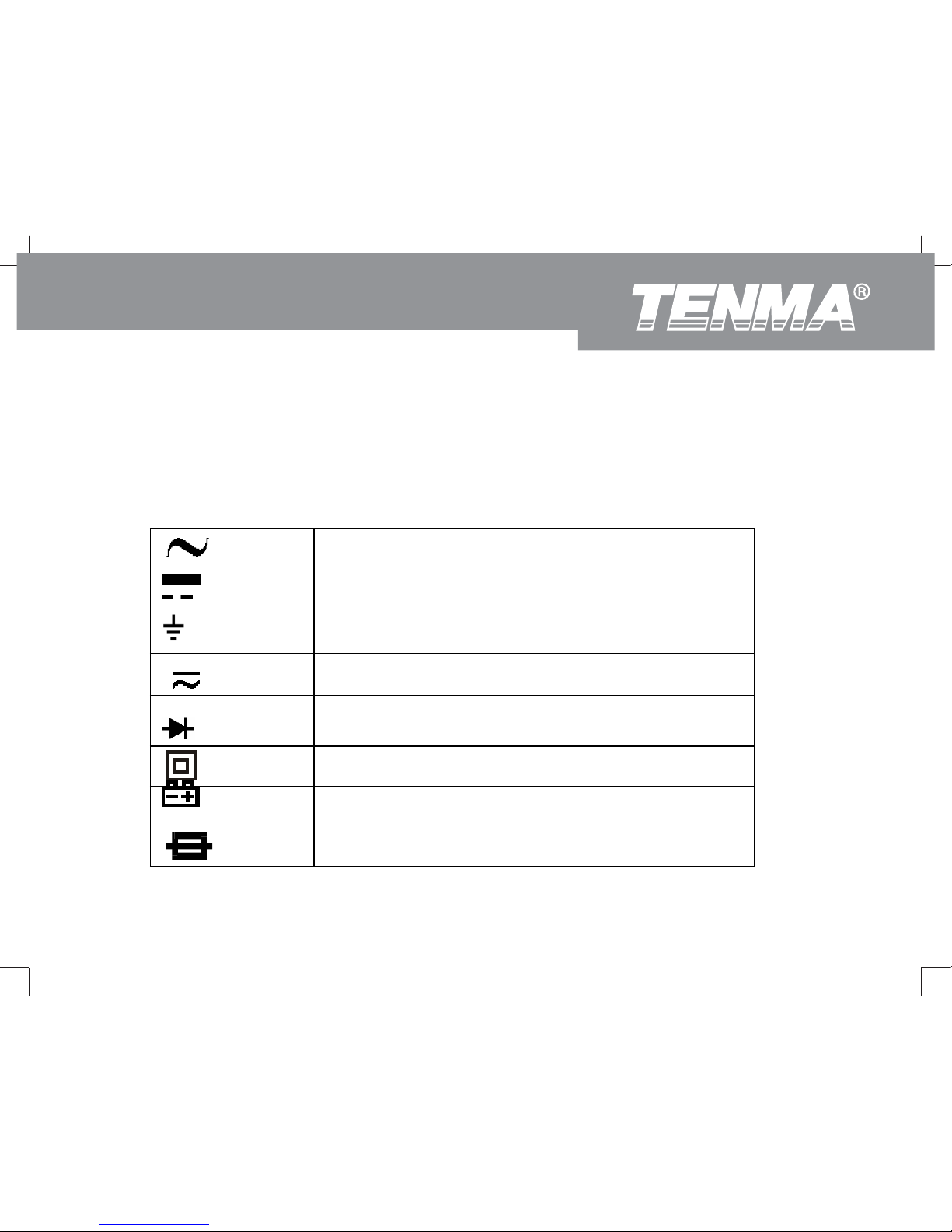
International Electrical Symbols
AC (Alternating Current)
DC (Direct Current)
Ground
V AC or DC
Diode
Double Insulated
Deficiency of Built-In Battery
Fuse
72-9280: OPERATING MANUAL
12
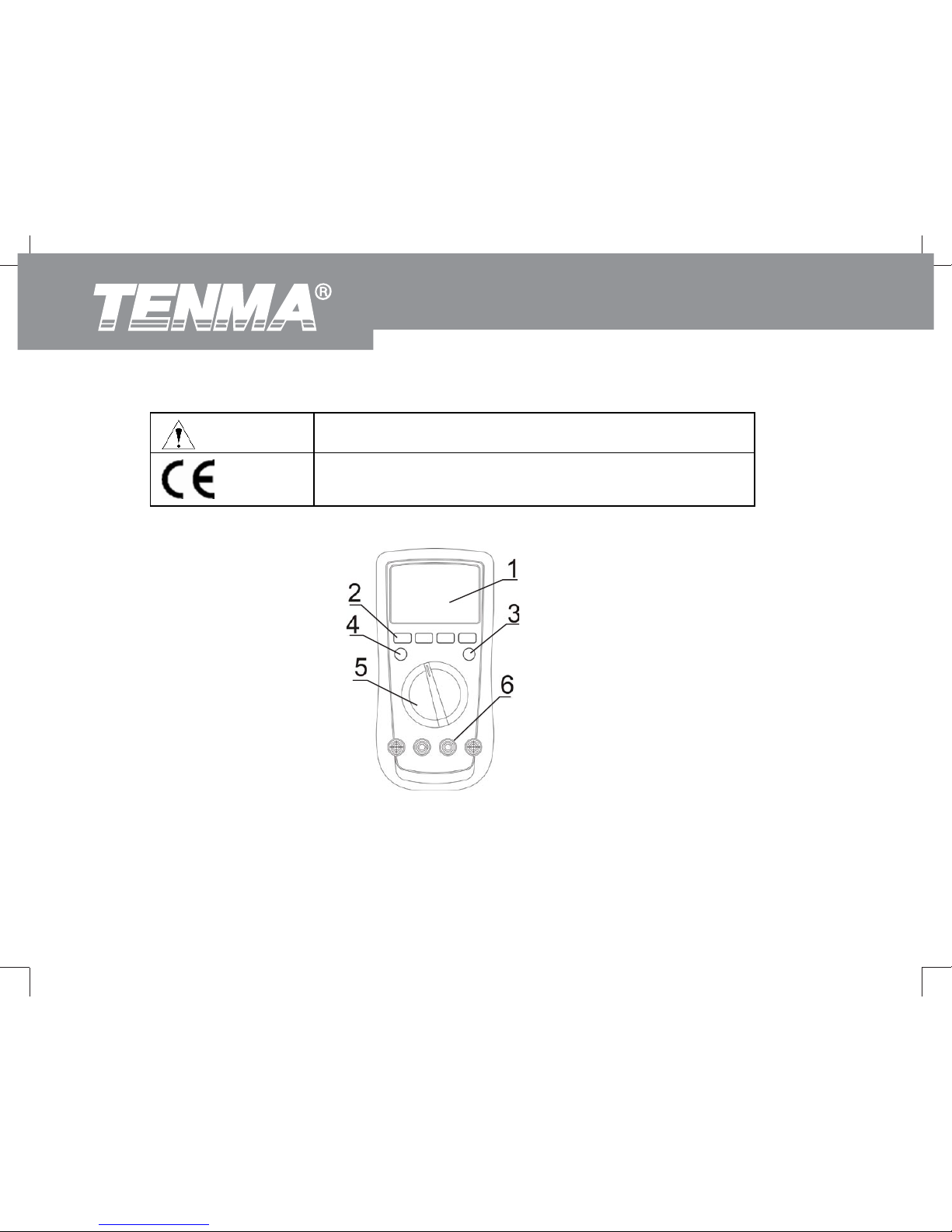
Warning. Refer to the Operating Manual.
Conforms to Standards of European Union.
The Meter Structure (see figure 1)
(Figure 1)
1. LCD display
2. Functional buttons
72-9280: OPERATING MANUAL
13
3. SELECT button
4 Power button
5 Rotary Switch
6 Input Terminals
Rotary Switch
Below table indicated for information about the rotary switch positions.
Rotary Switch
Position
Function
V
AC or DC Voltage Measurement
mV
Millivoltage Measurement
ȍ
Resistance Measurement
Capacitance measurement
Continuity Test
Diode Test
Hz Frequency Measurement
ȝA Current measurement, unit: ȝA
72-9280: OPERATING MANUAL

14
mA Current measurement, unit: mA
A Current measurement, unit: A
RPM x 10
Automotive engine tach testing (Displayed Reading x 10), Unit: rpm
DWELL
Automotive ignition dwell testing, Unit: degree
Functional Buttons (see figure 2)
Below table indicated for information about the functional button operations.
Figure 2
Button Operation Performed
POWER
Turn the power on and off.
72-9280: OPERATING MANUAL
15
HOLD/ z Press HOLD once to enter hold mode.
z Press HOLD again to exit hold mode and the present value is shown.
z Press and hold for 2 seconds to turn the display backlight on or off.
MAX/MIN Start recording of maximum and minimum values.
Press to step the display through high (MAX) and low (MIN) readings at any time.
Hz z Press once to enter Frequency measurement mode.
z Press and hold for 2 seconds to enter RS232C or USB mode.
RANGE
z Press RANGE to enter the manual ranging mode;
z Press and hold RANGE for 2 seconds to return to auto ranging mode;
z Under RPM or Dwell testing mode, press RANGE to select 4CYL, 6CYL, or
8CYL.
SELECT Press SELECT to select the alternate functions.
72-9280: OPERATING MANUAL
16
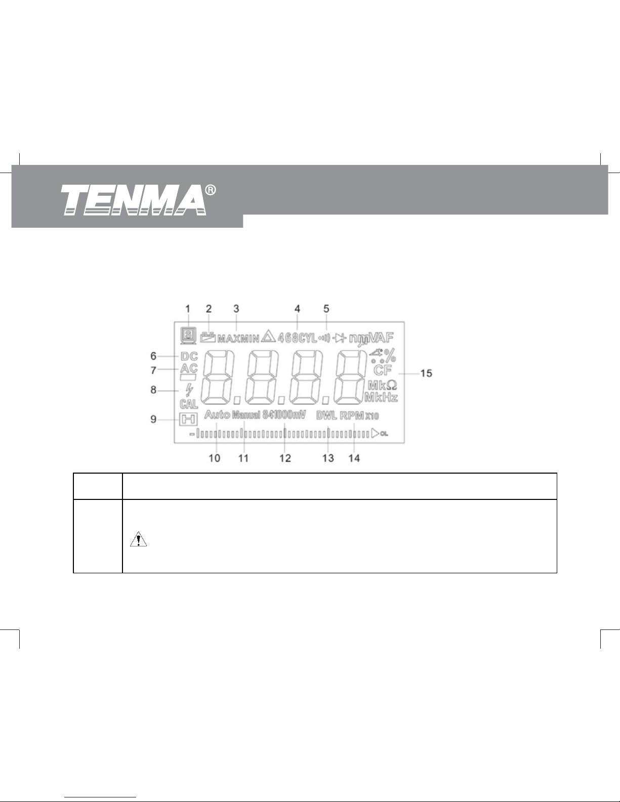
Display Symbols (see figure 3)
Figure 3
1 Data output is in progress.
2 Low Battery
Warning: To avoid false readings, which could lead to possible electric shock
or personal injury, replace the battery as soon as the battery indicator appears.
72-9280: OPERATING MANUAL
17
3 Maximum or Minimum reading displayed
4 4CYL, 6CYL, or 8CYL displayed
5 Test of continuity
6 Indicates for DC voltage or current
7 Indicates for AC voltage or current
8 Indicates for dangers
9 Data hold is active
10 The meter is in Auto range mode
11 The meter is in Manual range mode
12 Indicates for 841000mV range
13 Test of DWL
72-9280: OPERATING MANUAL
18
14 Test of RPM
15 Indicates for units
Measurement Operation
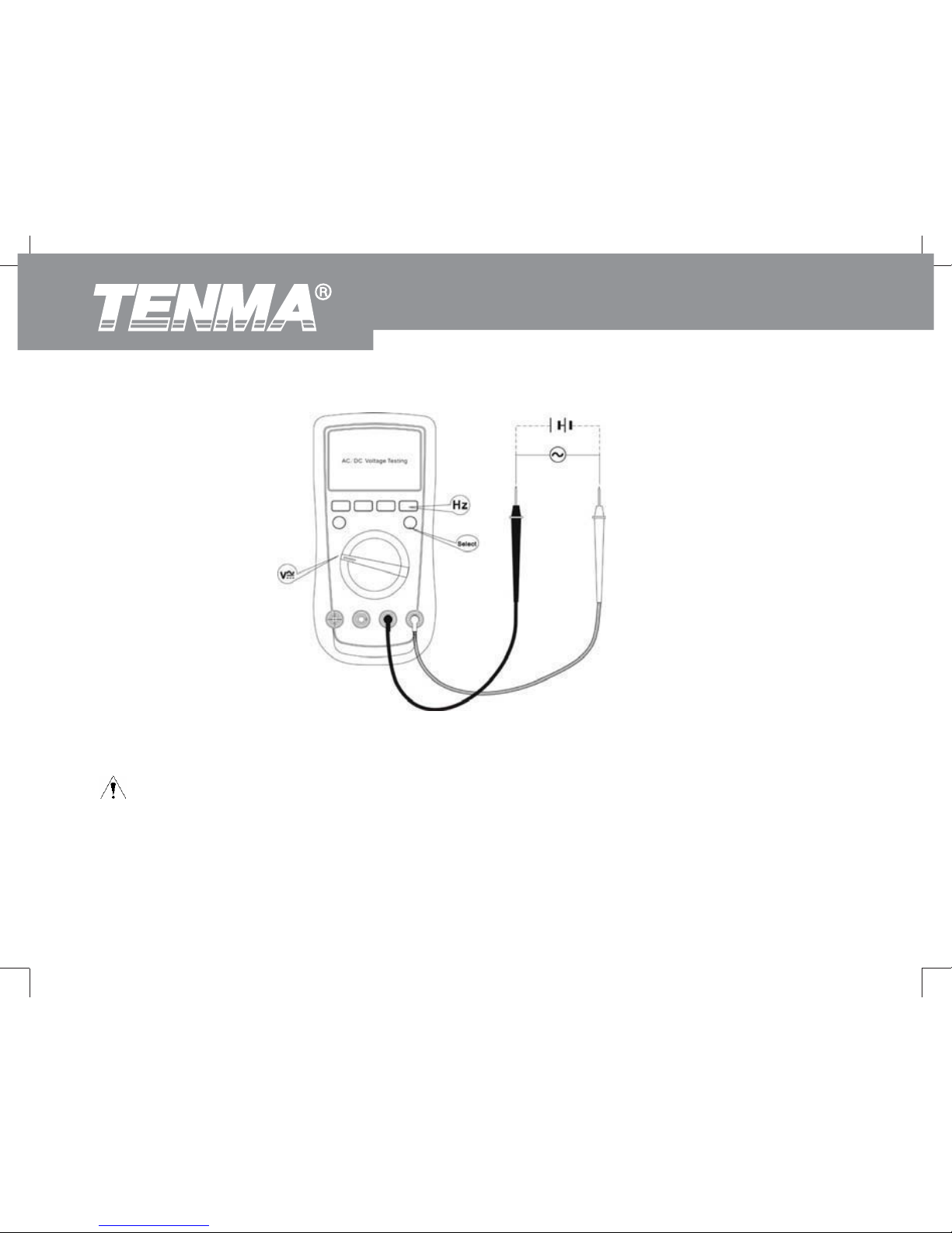
AC/DC Voltage Testing
Warning
To avoid injury or damage to the meter from electric shock, please do not attempt to measure
voltages higher than 1000V, although readings may be obtained. Please take extra care when
measuring high voltages to avoid electric shock.
To measure DC voltage, connect the Meter as follows:
1. nsert the red test lead into the V terminal and the black test lead into the COM terminal.
2. Set the rotary switch to an appropriate measurement position in V
press blue button to
switch between AC and DC measurement mode.
3. AC voltage measurement displays True RMS value. Press Hz button to obtain the frequency
value (refer to accuracy specifications for maximum ranges).
4. onnect the test leads with the object being measured. The measured value shows on the
display.
72-9280: OPERATING MANUAL

19
Note
Ɣ If the value of voltage to be measured is unknown, use the maximum measurement position
(1000V) and reduce the range step by step until a satisfactory reading is obtained.
Ɣ Please take extra care when measuring high voltages to avoid electric shock.
Ɣ In each range, the Meter has an input impedance of approximately 10Mȍ. this loading effect can
cause measurement errors in high impedance circuits. If the circuit impedance is less than or equal to
10kȍ, the error is negligible (0.1% or less).
Ɣ When voltage measurement has been completed, disconnect the testing leads and the circuit
under test.
72-9280: OPERATING MANUAL
20
(Figure 4)
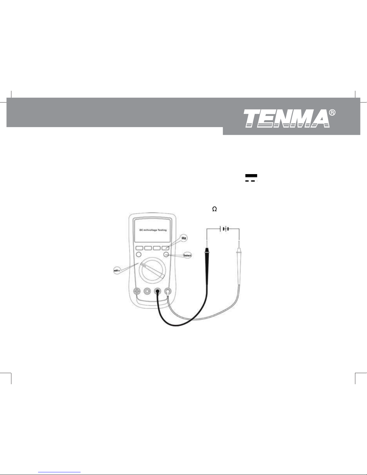
DC Millivoltage Testing
Warning
To avoid injury to you or damages to the Meter from electric shock, please do not attempt to
measure voltages higher than the range although readings may be obtained.
When AC voltage measurement has been completed, disconnect the connection between the
testing leads and the circuit under test.
72-9280: OPERATING MANUAL
21
To measure DC millvoltage, connect the Meter as follows:
1. Insert the red test lead into the V terminal and the black test lead into the COM terminal.
2. Set the rotary switch to an appropriate measurement position in mV
3. Connect the test leads with the object being measured.
The measured value shows on the display. Press Hz button to obtain the frequency value. (refer to
accuracy specifications for maximum ranges).
4. The Meter has an input impedance of approx. 4000M
.
(Figure 5)
72-9280: OPERATING MANUAL

22
Warning
Before connecting the Meter in serial to the tested in-circuit, disconnect in-circuit power.
If the fuse burns out during measurement, the Meter may be damaged or the operator himself
may be hurt.
Use proper terminals, function, and range for the measurement. When the testing leads are
connected to the current terminals, do not parallel them across any circuit otherwise it will
burn the fuse or damage to the Meter.
To measure AC/DC current, connect the Meter as follows:
1. nsert the red test lead into the “ȝA” “mA” or “A” terminal and the black test lead into
the COM terminal.
2. Set the rotary switch to an appropriate measurement position in “ȝA” “mA” or “A” .
Press blue button to switch between AC and DC measurement mode.
3. C current measurement displays true rms value. Press Hz button to obtain the frequency value
(refer to accuracy specifications for maximum ranges).
4. onnect the test leads with the object being measured. The measured value shows on the
display.
Note
Ɣ
If the value of the current to be measured is unknown, use the maximum measurement position
10A terminal, and reduce the range step by step until a satisfactory reading is obtained.
Ɣ When current measurement has been completed, disconnect the connection between the testing
leads and the circuit under test.
Ɣ When measuring 5A~10A: maximum continuous measurement should be 10 seconds
AC/DC Current Testing
72-9280: OPERATING MANUAL

23
and interval time between 2 measurement greater than 15 minutes.
(Figure 6)
Resistance Testing
Warning
To avoid damages to the Meter or to the devices under test, disconnect circuit power and
discharge all the high-voltage capacitors before measuring resistance.
To avoid injury to yourself, never attempt to input an effective voltage over 60V in DC or 30V in
AC.
72-9280: OPERATING MANUAL

24
To measure resistance, connect the Meter as follows:
1. Insert the red test lead into the ȍ terminal and the black test lead into the COM terminal.
2. Set the rotary switch to an appropriate measurement position in ȍ range then press blue button
to select resistance measurement mode.
3. Connect the test leads with the object being measured.
The measured value shows on the display.
Note
Ɣ When there is no input, for example in an open circuit, the Meter displays “OL”.
Ɣ If the resistance reading 0.5ȍ when you short-circuit the leads, please check for loose test leads
or other reasons.
Ɣ For high resistance (>1Mȍ), it is normal to take several seconds to obtain a stable reading. For
better accuracy, choose a shorter test lead.
Ɣ When resistance measurement has been completed, disconnect the connection between the
testing leads and the circuit under test.
72-9280: OPERATING MANUAL
 Loading...