

Page 1

Model 72-8155: OPERATING MANUAL
1
Table of Contents
Title Page
Overview
Inspection
Safety Information
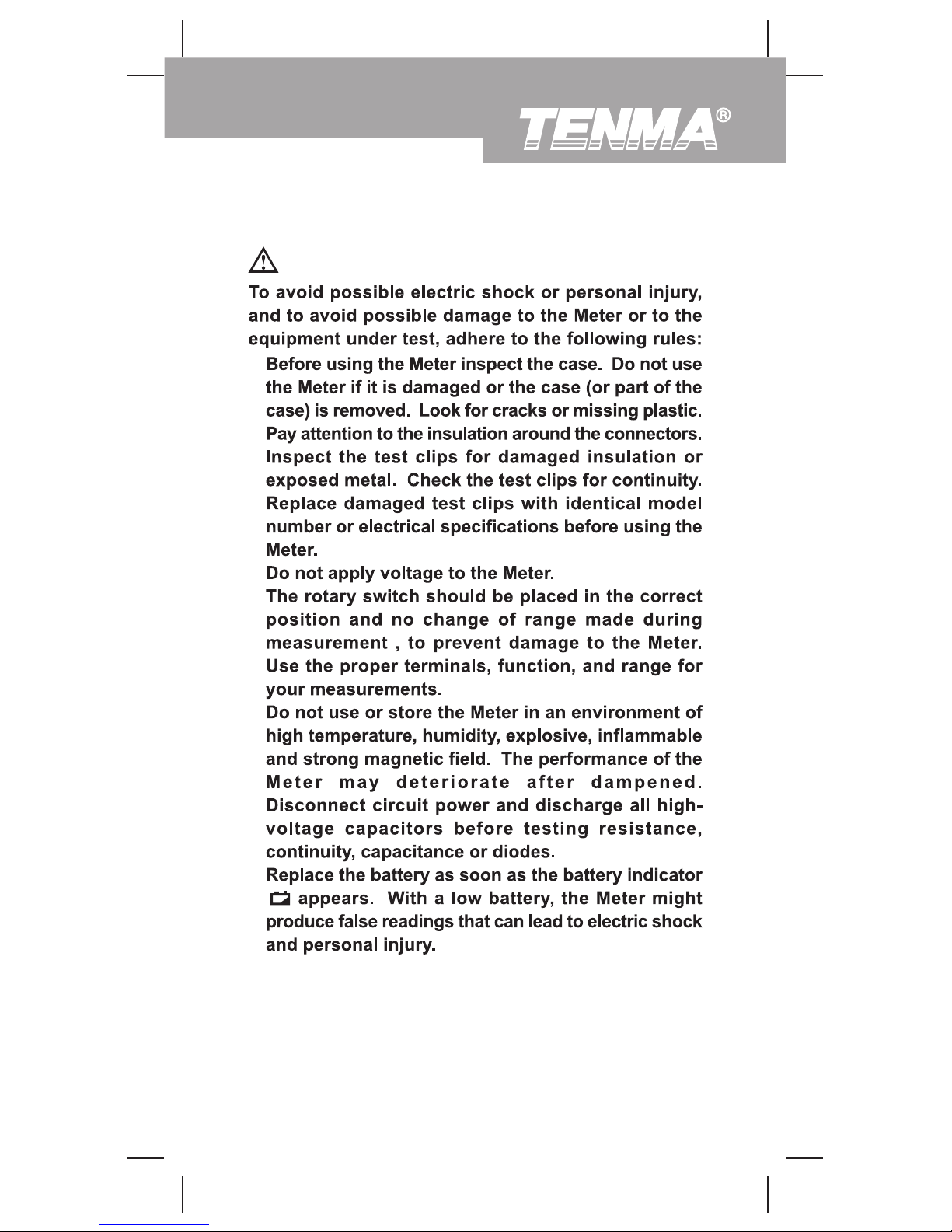
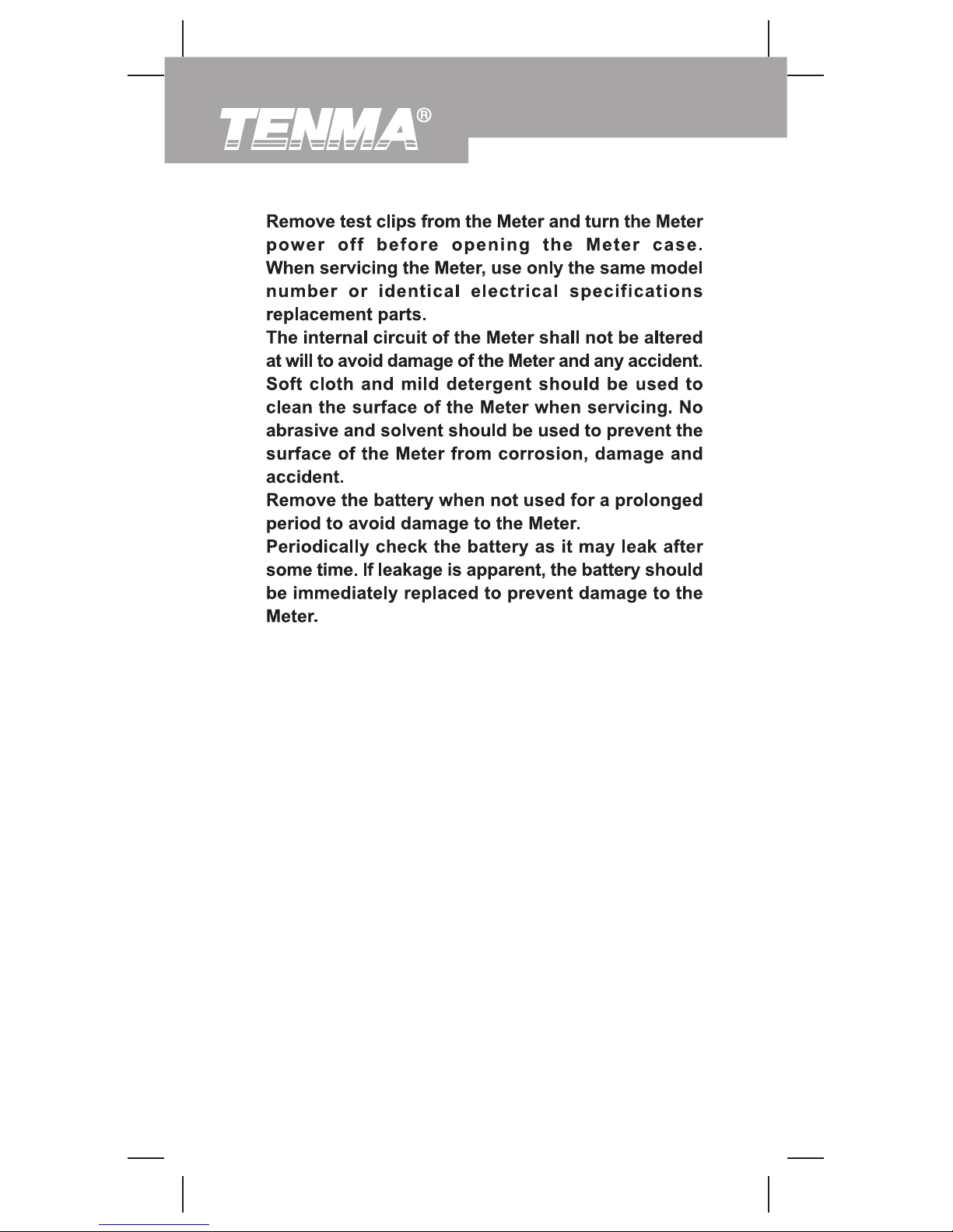
Rules For Safe Operation
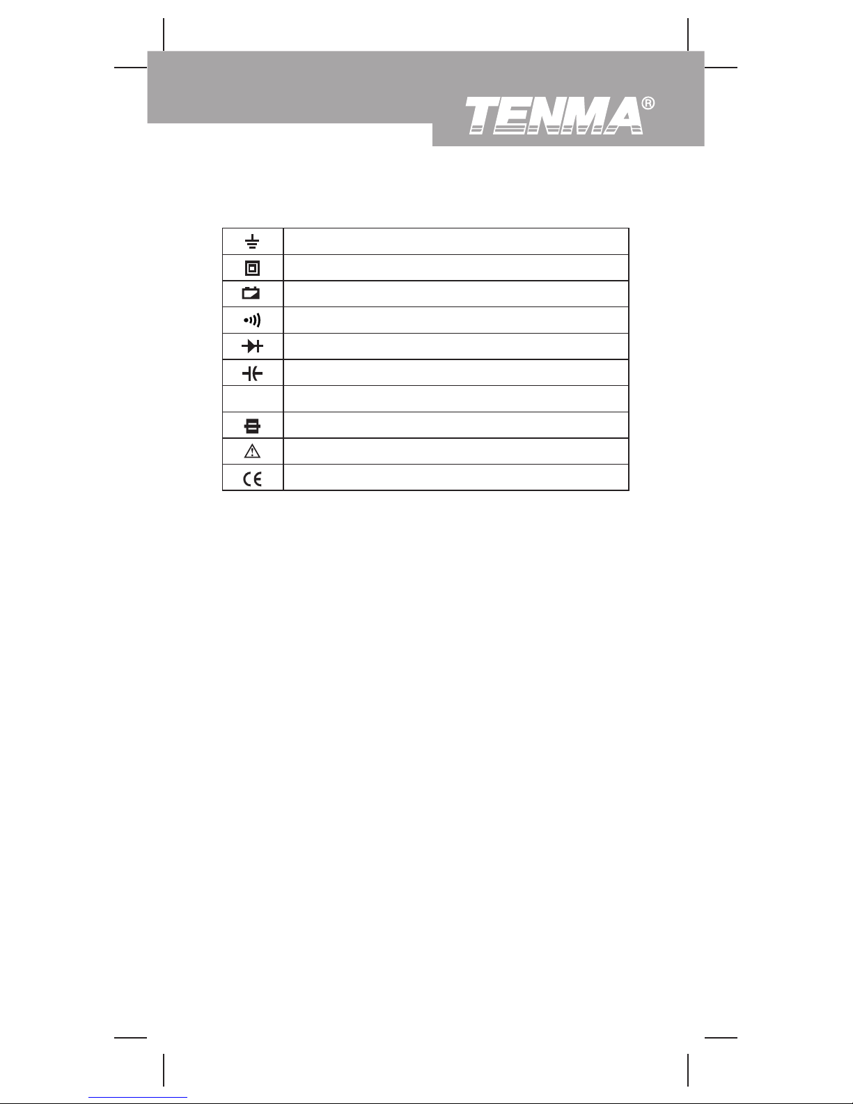
International Electrical Symbols
The Meter Structure
Functional Buttons
Display Symbols
Measurement Operation
A. Measuring Resistance
B. Diode and Continuity Test
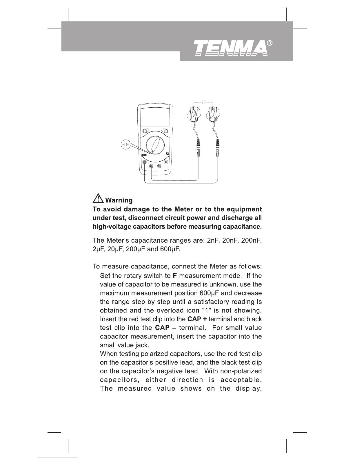
C. Capacitance Measurement
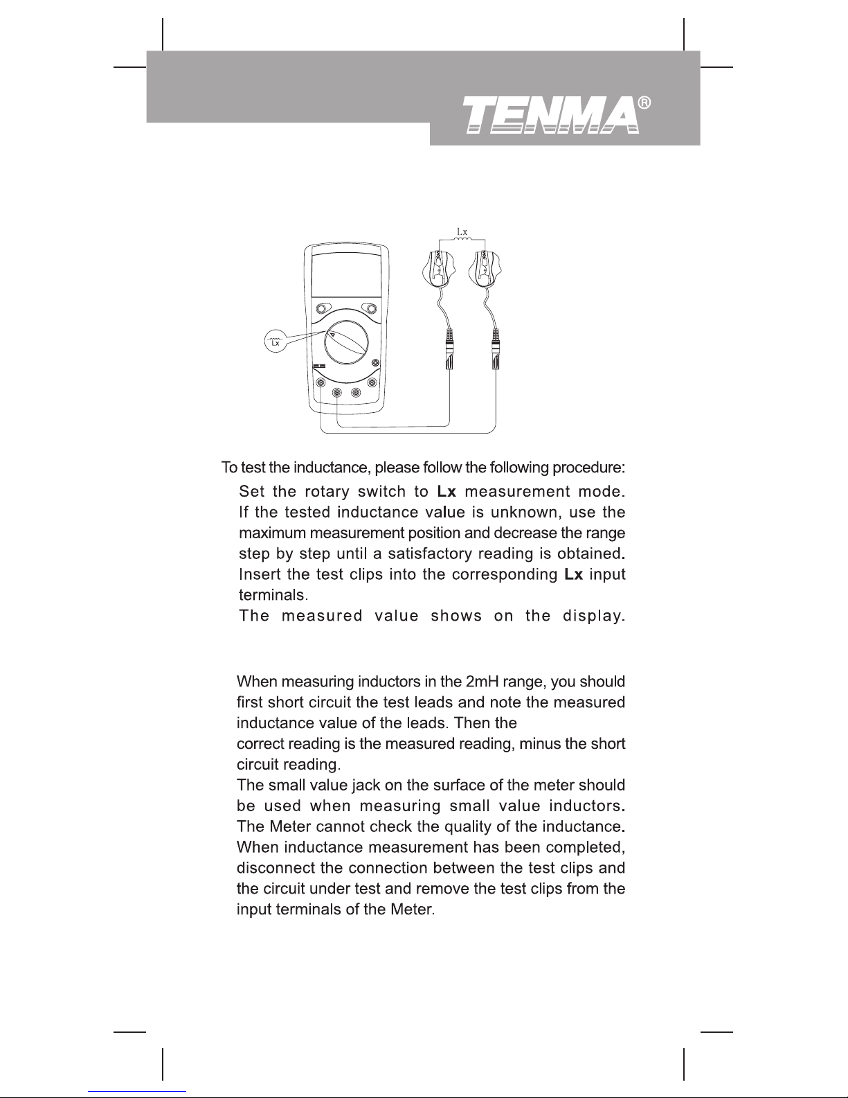
D. Inductance Measurement
E. Transistor hFE Measurement
General Specifications
Accuracy Specifications
A. Resistance Test
B. Continuity & Diodes
C. Capacitance Test
D. Inductance Test
E. Transistor
Maintenance
A. General Service
B. Replacing the Battery
C. Replacing the Fuse
3
4
4
5
7
8
9
10
11
11
13
15
17
18
19
20
20
21
21
22
22
23
23
24
25
Page 2

Model 72-8155: OPERATING MANUAL
2
Page 3

To avoid electric shock or personal injury, read the
ìSafety Informationî and ìRules for Safety Operationî
carefully before using the Meter.
Warning
Model 72-8155: OPERATING MANUAL
3
Overview
This Operating Manual covers information on safety and
cautions. Please read the relevant information carefully
and observe all the Warnings and Notes strictly.
Digital Inductance Capacitance Meter Model 72-8155
(hereafter referred to as ìthe Meterî) is a 3 1/2 digits with
steady operations, fashionable design and highly reliable
hand-held measuring instrument.
The Model 72-8155 will measure capacitance, inductance,
resistance, transistor hFE and test diodes. It will also test
continuity with an audible buzzer.
Page 4
Model 72-8155: OPERATING MANUAL
4
Inspection
Open the package case and take out the Meter. Check
the following items carefully to see if any items are missing
or damaged.
Item Description Qty
1
2
3
Operating Manual
Test Clip
9V Alkaline Battery (NEDA1604, 6F22
or 006P) (installed)
1 piece
1 pair
1 piece
In the event you find any items missing or damaged, please
contact your dealer immediately.
Safety Information
This Meter complies with the standards EMC EN61326.
Use the Meter only as specified in this operating manual,
otherwise the protection provided by the Meter may be
impaired.
In this manual, a Warning identifies conditions and actions
that pose hazards to the user, and may damage the Meter
or the equipment under test.
A Note identifies the information that user should pay
attention to.
International electrical symbols used on the Meter and in
this Operating Manual are explained on page 7.
Page 5
Warning
l
l
l
l
l
l
l
l
Rules For Safe Operation
Model 72-8155: OPERATING MANUAL
5
Page 6
l
l
l
l
l
l
Model 72-8155: OPERATING MANUAL
6
Page 7
Lx
Model 72-8155: OPERATING MANUAL
7
International Electrical Symbols
Ground
Double Insulated
Low Battery.
Continuity Test.
Diode.
Capacitance Test
Inductance Test
Fuse.
Warning. Refer to the Operating Manual.
Conforms to Standards of European Union.
Page 8
Model 72-8155: OPERATING MANUAL
72-8155
8
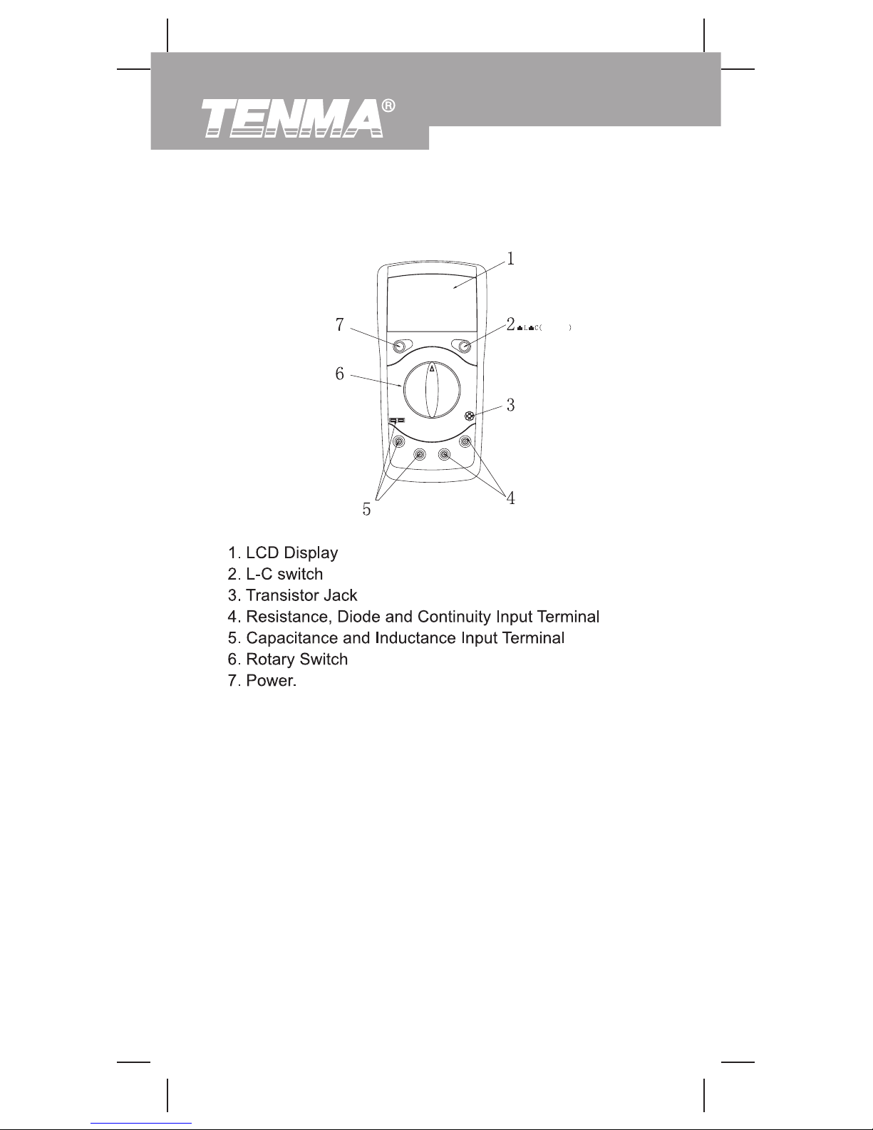
The Meter Structure (see figure 1)
(figure 1)
Page 9

Power
L-C
Model 72-8155: OPERATING MANUAL
9
Functional Buttons
The following table provides information regarding the
functional button operation.
Button Description
Press the Power down to turn the Meter on.
Press the Power again to turn the Meter power off.
Press L-C down to enter the Capacitance
measurement mode.
Press L-C up to enter the Inductance measurement
mode.
Page 10
β
Model 72-8155: OPERATING MANUAL
10
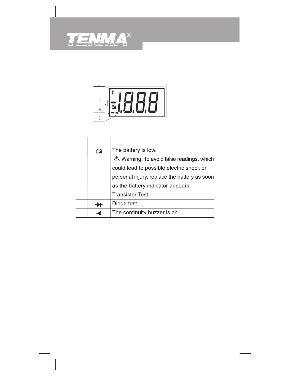
Display Symbols (see figure 2)
(figure 2)
No.
Symbol
Meaning
1
2
3
4
Page 11
l
l
1.
2.
3.
Model 72-8155: OPERATING MANUAL
11
Measurement Operation
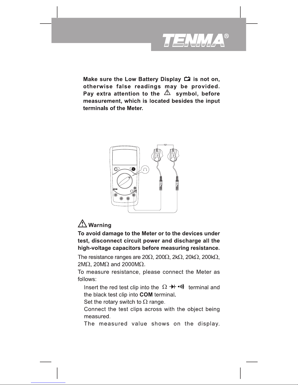
A. Measuring Resistance (see figure 3)
(figure 3)
Page 12
l
l
l
l
Model 72-8155: OPERATING MANUAL
12
Note
Page 13
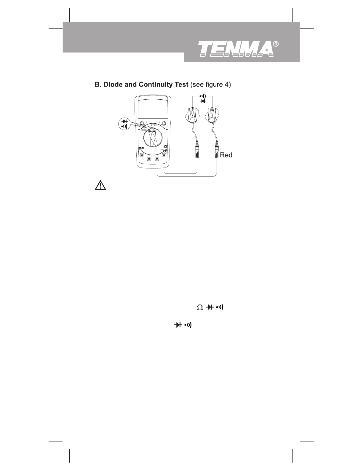
T o avoid damage to the Meter or to the devices under
test, disconnect circuit power and discharge all the
high-voltage capacitors before measuring diodes and
continuity.
Warning
Testing Diodes
Insert the red test clip into the terminal and
the black test clip into the COM terminal.
Set the rotary switch to .
For forward voltage drop readings on any semiconductor
component, place the red test clip on the componentís
anode and place the black test clip on the componentís
cathode.
The display shows the diode forward voltage dropís
nearest value.
1.
2.
3.
Use the diode test to check diodes, transistors, and other
semiconductor devices. The diode test sends a current
through the semiconductor junction, and then measures
the voltage drop across the junction. A good silicon junction
drops between 500mV and 800mV.
To test a diode out of a circuit, connect the Meter as follows:
Model 72-8155: OPERATING MANUAL
13
(figure 4)
Page 14
l
l
l
1.
2.
3.
4.
5.
l
l
Model 72-8155: OPERATING MANUAL
14
Note
Note
Page 15
1.
2.
3.
4.
Model 72-8155: OPERATING MANUAL
15
C. Capacitance Measurement (72-8155 only, see figure 5)
(figure 5)
Page 16
l
l
l
l
Model 72-8155: OPERATING MANUAL
16
Note
Page 17
l
l
l
l
Model 72-8155: OPERATING MANUAL
17
D. Inductance Measurement (see figure 6)
(figure 6)
1.
2.
3.
4.
Remarks:
Page 18

l
Model 72-8155: OPERATING MANUAL
18
(figure 7)
1.
2.
3.
4.
Note:
Page 19
l
l
l
l
l
l
l
l
l
l
l
l
l
l
l
Model 72-8155: OPERATING MANUAL
19
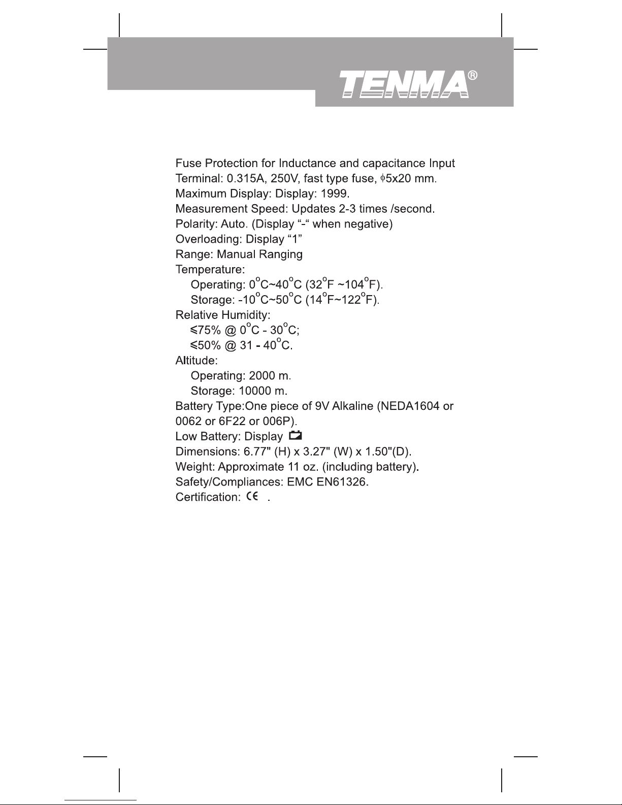
General Specifications
Page 20
l
l
l
Model 72-8155: OPERATING MANUAL
20
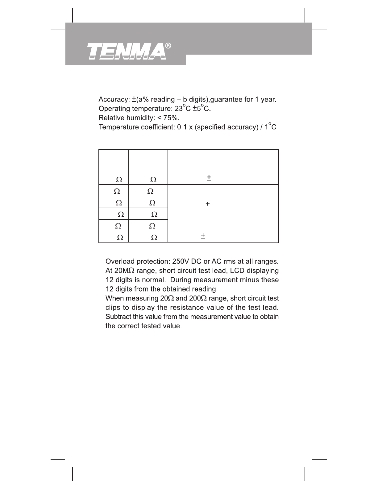
Accuracy Specifications
A. Resistance Test
Range Resolution Accuracy
200
2k
20k
200k
2M
20M
0.1
1
10
100
1k
10k
Remarks:
(0.8%+3)
(0.8%+1)
[2%(rdg-12)+5]
Page 21
l
l
l
l
l
Model 72-8155: OPERATING MANUAL
21
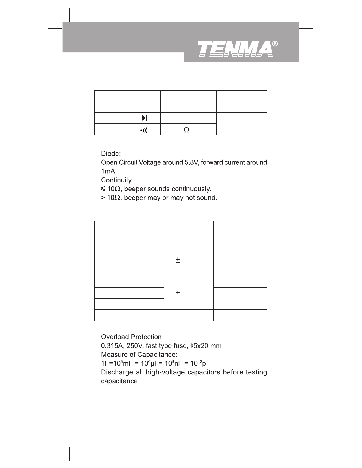
B. Continuity & Diodes
Range Resolution
Overload
Protection
Function
Diode
Continuity
1mV
1
250V rms
Remarks:
C. Capacitance Test
Range Resolution Accuracy
Testing Frequ-
ency / Voltage
2.000nF
20.00nF
200.0nF
2.000µF
20.00µF
200.0µF
600µF
0.001nF
0.01nF
0.1nF
0.001µF
0.01µF
0.1µF
0.001mF
(1%+5)
(4%+5)
Reference only
1kHz/150mV
100Hz/15mV
100Hz/1.5mV
Remarks:
Page 22
l
l
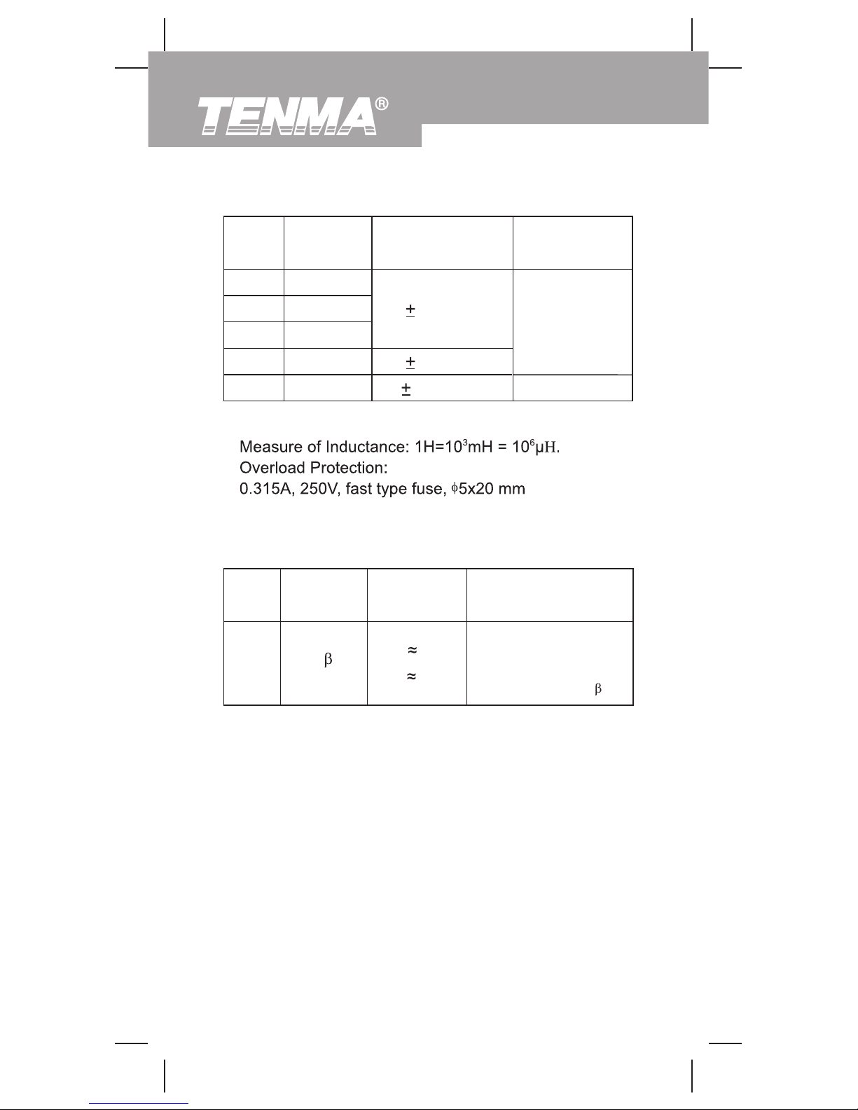
The display value is the
tested transistorís
(NPN, PNP) nearest
value (0~1000 )
Model 72-8155: OPERATING MANUAL
22
E. Transistor
Range Resolution Remarks
hFE
Vce 5.8V
I bo
10µA
Testing
Condition
1
D. Inductance Test
Range Resolution Accuracy
Tested Frequ-
ency / Current
2mH
20mH
200mH
2H
20H
0.001mH
0.01mH
0.1mH
0.001H
0.01H
(2%+8)
(5%+5)
(5%+15)
1kHz/150µA
100Hz/15µA
Remarks:
Page 23
l
l
l
l
Model 72-8155: OPERATING MANUAL
23
Maintenance
Page 24
Warning
1.
2.
3.
4.
5.
Model 72-8155: OPERATING MANUAL
24
(figure 8)
To replace the battery:
Page 25
Warning
To replace the Meterís fuse:
1.
2.
3.
4.
5.
6.
7.
(figure 9)
SCREW
25
Model 72-8155: OPERATING MANUAL
Page 26
26
Model 72-8155: OPERATING MANUAL
 Loading...