

Page 1
1
Models: 72-2685, 72-2690, 72-2695, 72-2700
72-2705, 72-2710, 72-2715 & 72-2720
Digital Control & Programmable DC Power Supply
Page 2

2
When using electrical appliances, basic safety precautions should always
be followed to reduce the risk of re, electric shock and injury to persons or
property.
Read all instructions before using the appliance and retain for future reference.
• Check that the voltage indicated on the rating plate corresponds with that of the
local network before connecting the appliance to the mains power supply.
• Do not operate this appliance with a damaged plug or cord, after a malfunction or
after being dropped or damaged in any way.
• Check the product before use for any damage. Should you notice any damage on
the cable or casing, do not use.
• This appliance contained no user-serviceable parts. All repairs should only be
carried out by a qualied engineer. Improper repairs may place the user at risk of
harm.
• This product must be grounded through the earth connection in the mains lead for
safe operation and to reduce ripple and noise.
• Do not block or obstruct the cooling vent opening.
• Avoid severe impacts or rough handling that leads to damage.
• Do not discharge static electricity.
• This appliance can be used by children aged from 8 years and above and persons
with reduced physical, sensory, or mental capabilities or lack of experience and
knowledge if they have been given supervision or instruction concerning use of the
appliance in a safe way and understand the hazards involved.
• Children should be supervised to ensure that they do not play with the appliance.
• Always disconnect from the mains when the product is not in use or before
cleaning.
• Do not use the appliance for any purpose other than that for which it is designed.
• Do not operate or store in an environment of high humidity or where moisture may
enter the product as this can reduce insulation and lead to electric shock.
IMPORTANT SAFETY INFORMATION
PRODUCT OVERVIEW
Main Features
• 4-digit display
• Low noise
• Cooling fan controlled by Heatsink temperature
• Constant voltage
• Digital panel control
• Software calibration
• Over Current Protection
• 2 adjusting modes of voltage and current
• Button lock function
WHAT’S INCLUDED
• Power Supply Unit
• Mains power lead
• User Manual
• Remote Control Interface
Page 3
3
OVERVIEW
Voltage and Current Adjustment Knob Operation
• There are two adjustment modes for the voltage and current levels - Mode 1 and
Mode 2.
Mode 1: before setting, press the controls to adjust the voltage and current levels.
Mode 2: adjust directly, there is no need to press the controls.
• These two modes can be switched between by pressing the voltage adjustment
control and the current adjustment control at the same time and holding for two
seconds.
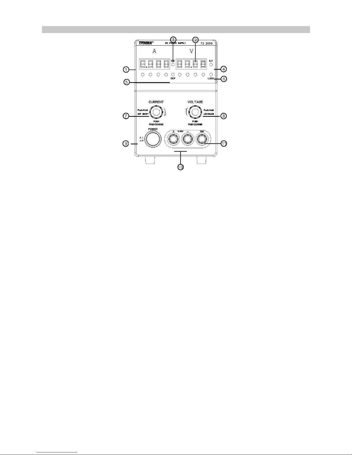
Front panel controls
1. Displays the setup value of the output current.
2. Voltmeter displays the setup value of the output voltage.
3. Constant current mode.
4. Constant voltage mode
5. Over current protection active.
6. Panel LOCK indicator.
7. Adjustment knob for current.
8. Adjustment knob for voltage.
9. Power ON/OFF button.
10. Output terminals.
Page 4
4
OPERATION
Mode 1 (ne adjustment)
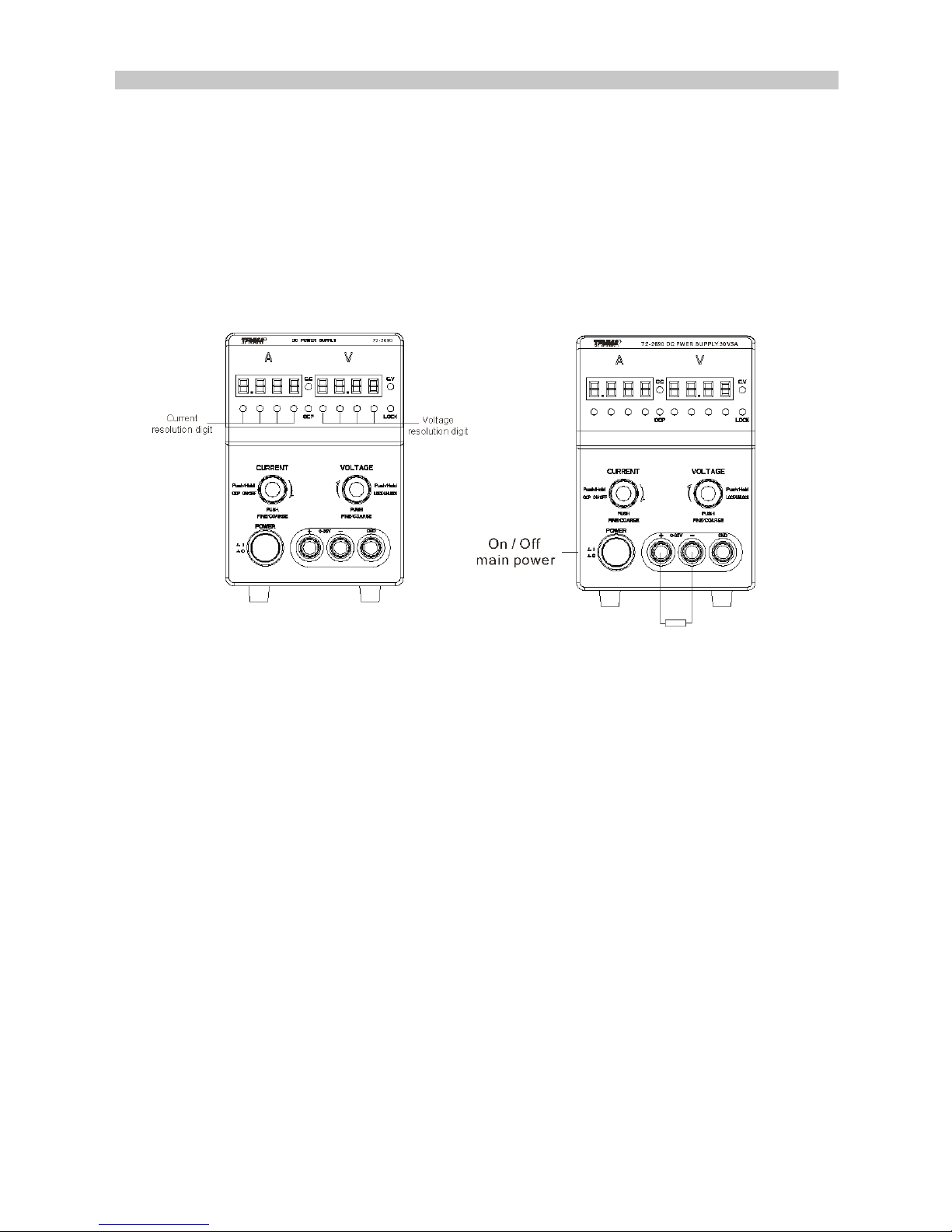
• Voltage adjustment control: Push the voltage adjustment control and then one of
the voltage indicators will light up, the voltage output can be changed by adjusting
the control.
Pushing the voltage control again changes the digit for ne adjustment.
• Current adjustment control: Push the current adjustment control and then one of the
current digit indicators will light up, the current output can be changed by adjusting
the control.
Pushing the voltage control again changes the digit for ne adjustment.
Mode 2 (coarse adjustment)
• In Mode 2, rotate the adjustment knobs to adjust the voltage and current values.
The default resolution of the voltage initial settings is 1V while that of the current is
100mA. The voltage and current adjusting resolution can be changed by pressing
the controls.
Lock Function
Press and hold the voltage control for three seconds to lock the front panel and then
press again and hold for 3 seconds to unlock.
Operation of Over Current Protection
Press and hold the current control for three seconds to start OCP mode, where the
output will be cut off when the output current reaches the set value. In the OCP mode,
press the control to recover the output.
PC Remote Control
COM setting: Congure the COM port settings on PC according to the following list:
• Baud rate: 9600
• Parity bit: None
• Data bit: 8
• Stop bit: 1
• Data ow control: None
Page 5
5
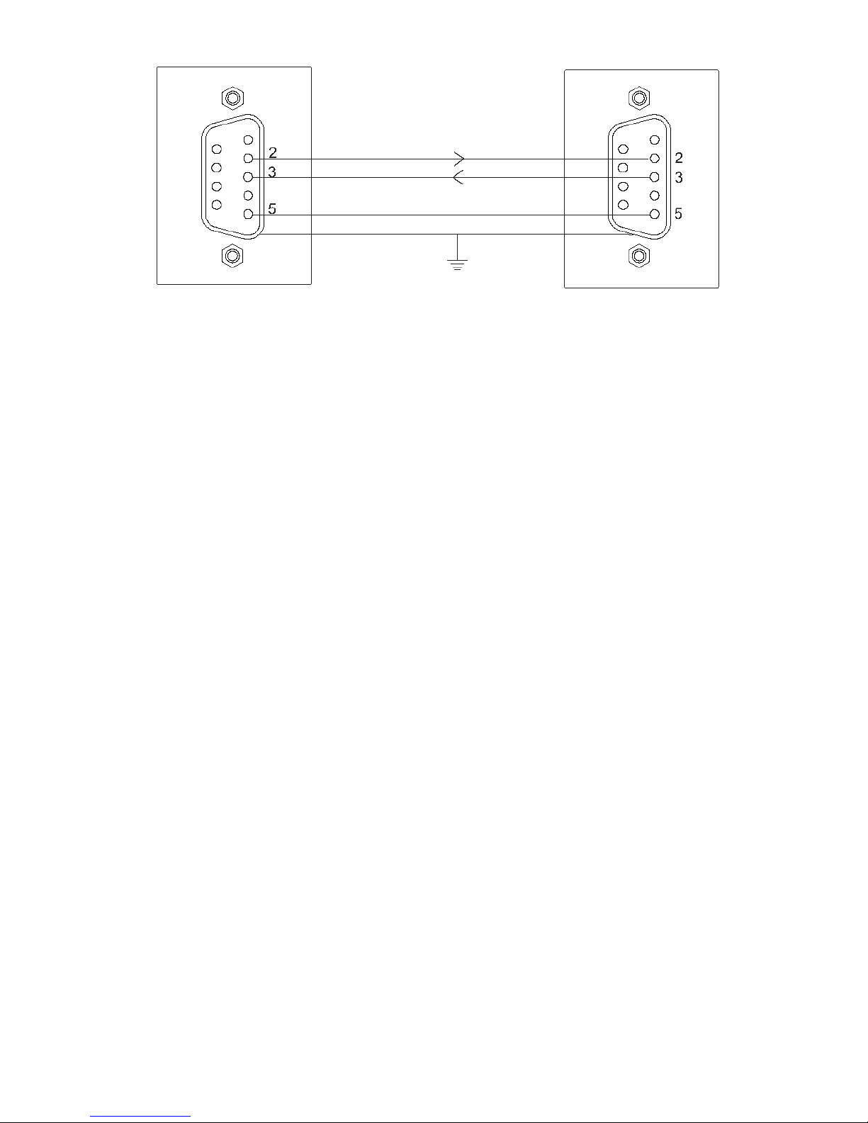
RS232 Interface Denition
Functionality check
Run this query command via the terminal application:- *DIN?
This should return the identication information: Manufacturer, model name and
software version.
ie:- TENMA 72-2705 Vx.xx
KD Series Remote Control Syntax V2.0
Command format: VSET<X>:<NR2>
1. VSET: Command header
2. X: Output channel
3. Separator
4. NR2: Parameter
Command details
1. ISET<X>:<NR2>
Description: Sets the output current Example: ISET1:2.225
Response time: 50ms
Sets the CH1 output current to 2.225A
2. ISET <X>?
Description: Returns the output current setting Example: ISET1?
Returns the CH1 output current setting.
3. VSET <X>: <NR2
Description: Sets the output voltage.
Example: VSET1:20.50.
Sets the CH1 voltage to 20.50V.
4. VSET <X>?
Description: Returns the output voltage setting. Example VSET1?
Returns the CH1 voltage setting.
5. IOUT<X>?
Description: Returns the actual output current. Example IOUT1?
Returns the CH1 output current.
6. VOUT <X>?
Description: Returns the actual output voltage. Example VOUT1?
Returns the CH1 output voltage.
DC Power Supply PC
Page 6

6
7. OUT<Boolean>
Description: Turns on or off the output.
Boolean: 0 OFF, 1 ON.
Example: OUT1 turns on the output.
8. STATUS?
Description: Returns the POWER SUPPLY status. Contents 8 bits in the following
format:
Bit Item Description
0 CH1 0=CC mode, 1=CV mode
1,2,3,4,5 N/A
6. Output 0=OFF, 1=ON
7. N/AN/A
9. *IDN?
Description: Returns the 72-2685 identication.
Example: *IDN?
10. RCL<NR1>
Description: Recalls a panel setting.
NR1 - 5: Memory number 1 to 5.
Example: RCL1 recalls the panel setting stored in memory number 1.
11. SAV<NR1>
Description: Stores the panel setting.
NR1 - 5: Memory number 1 to 5
Example: SAV1 stores the panel setting in memory number 1.
12. OCP<NR1>
Description: Over current.
Example: OCP1 OCP OPEN.
Page 7
7
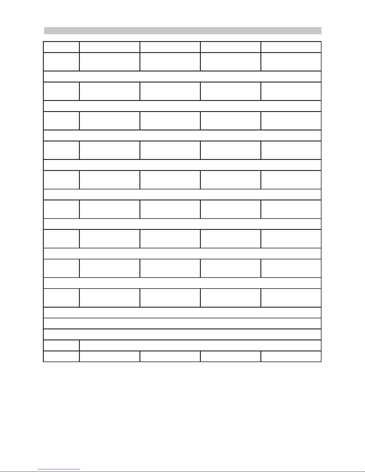
SPECIFICATIONS
Models 72-2685/72-2705 72-2960/72-2710 72-2695/72-2715 72-2700/72-2720
Voltage
Current
0-30V
0-3A
0-30V
0-5A
0-60V
0-2A
0-60V
0-3A
Load Regulation
Voltage
Current
≤0.01%+2mV
≤0.1%+5mA
≤0.01%+2mV
≤0.1%+5mA
≤0.01%+2mV
≤0.1%+5mA
≤0.01%+2mV
≤0.1%+5mA
Line Regulation
Voltage
Current
≤0.01%+3mV
≤0.1%+3mA
≤0.01%+3mV
≤0.1%+3mA
≤0.01%+3mV
≤0.1%+3mA
≤0.01%+3mV
≤0.1%+3mA
Setup Resolution
Voltage
Current
10mV
1mA
10mV
1mA
10mV
1mA
10mV
1mA
Setup Accuracy (-5°C to 25°C)
Voltage
Current
≤0.5%+20mV
≤0.5%+5mA
≤0.5%+20mV
≤0.5%+10mA
≤0.5%+30mV
≤0.5%+5mA
≤0.5%+30mV
≤0.5%+5mA
Ripple (20-20m)
Voltage
Current
≤1mVrms
≤3mArms
≤2mVrms
≤3mArms
≤1mVrms
≤3mArms
≤1mVrms
≤3mArms
Temperature Coefcient
Voltage
Current
≤150ppm
≤150ppm
≤150ppm
≤150ppm
≤150ppm
≤150ppm
≤150ppm
≤150ppm
Read Back Resolution
10mV
1mA
10mV
1mA
10mV
1mA
10mV
1mA
Read Back Temperature Coefcient
≤150ppm
≤150ppm
≤150ppm
≤150ppm
≤150ppm
≤150ppm
≤150ppm
≤150ppm
Interfaces
USB RS232, for models 72-2705, 72-2710, 72-2715 & 72-2720
Weight & Dimensions
(WxHxD) 110x156x260mm
4kg 4kg 4.8kg 4.8kg
Page 8
8
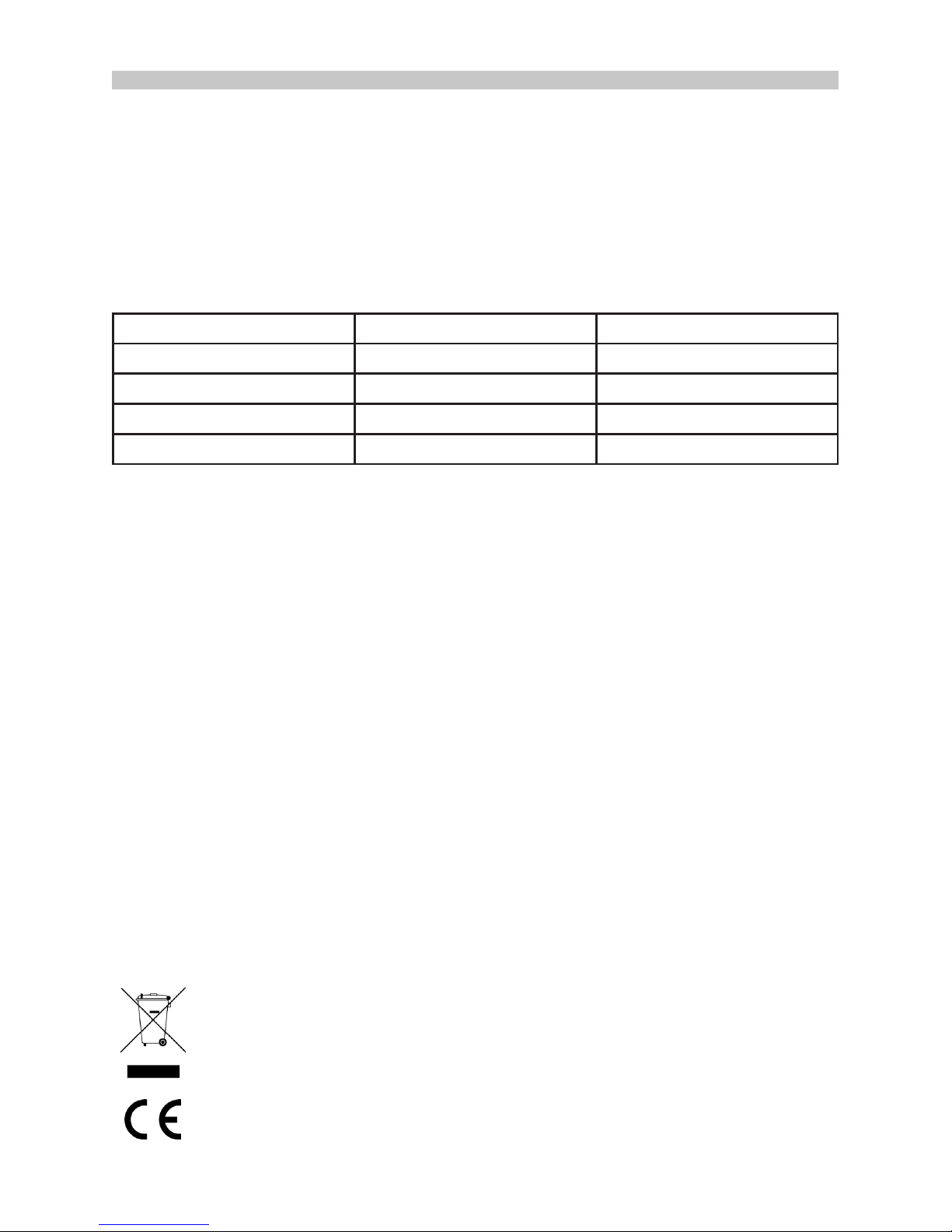
INFORMATION ON WASTE DISPOSAL FOR CONSUMERS OF ELECTRICAL &
ELECTRONIC EQUIPMENT.
When this product has reached the end of its life it must be treated as Waste
Electrical & Electronic Equipment (WEEE). Any WEEE marked products must not be
mixed with general household waste, but kept separate for the treatment, recovery
and recycling of the materials used. Contact your local authority for details of recycling
schemes in your area.
Made in China. PR2 9PP
Man Rev 1.0
MAINTENANCE
Cleaning
• Use a damp cloth and a small amount of liquid detergent if necessary.
• Never submerse the power supply in liquid or allow any liquid to enter the case.
• Do not use any chemicals, abrasives or solvents that could damage the power
supply casing.
Changing the fuse
• Replace the fuse only with one of exactly the same type and rating.
• Disconnect the mains power and unplug the mains lead before replacing the fuse.
Model 110/120V 220/230V
72-2685/72-2705 T4A/250V T2A/250V
72-2690/72-2710 T5A/250V T3A/250V
72-2695/72-2715 T5A/250V T3A/250V
72-2700/72-2720 T5A/250V T3A/250V
 Loading...