

Page 1
1
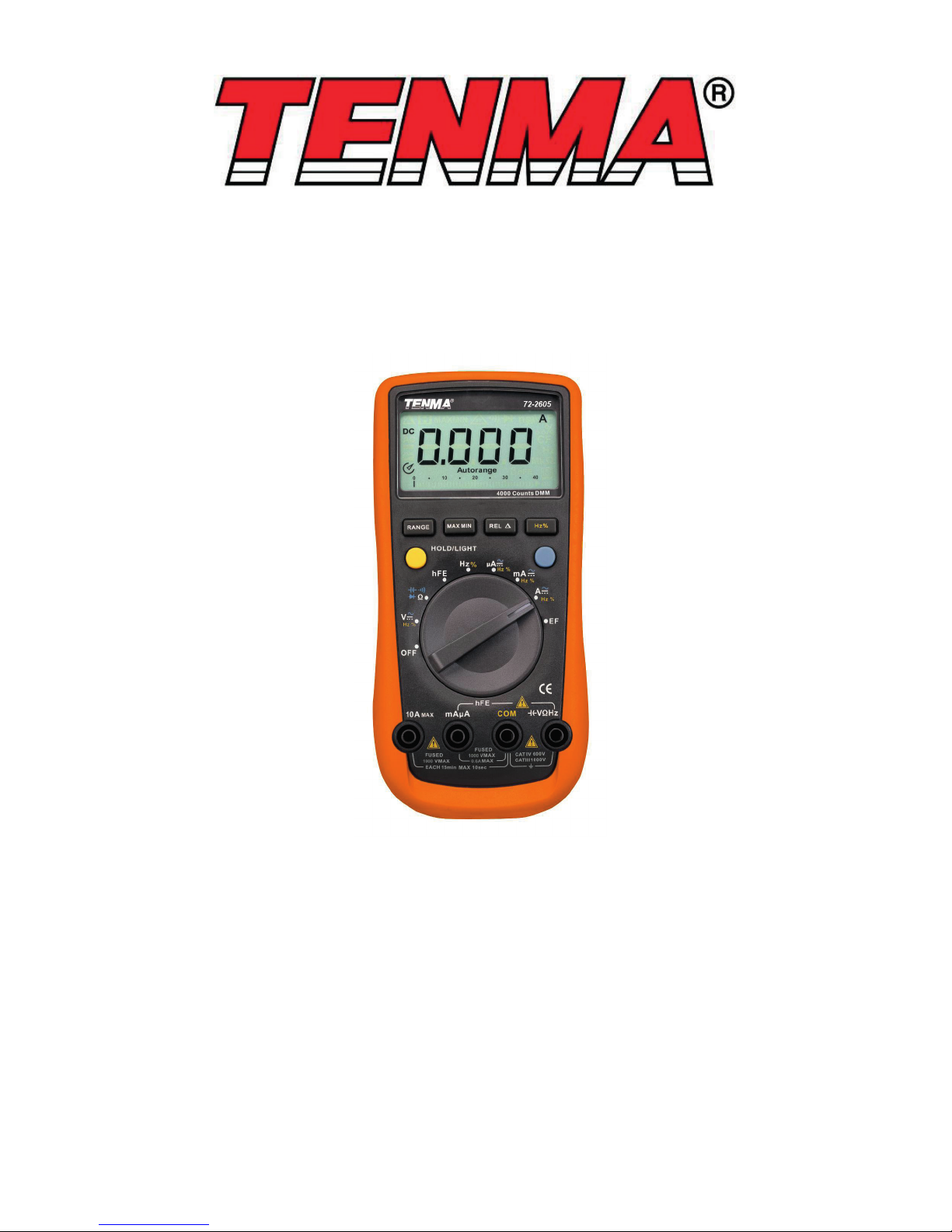
Model: 72-2605, 72-2610
72-10405 and 72-10410 and 72-10415
Digital Multimeter
Page 2
2
Please read these instructions carefully before use and retain for future
reference.
This instrument is designed and manufactured in compliance with: G84793,
lEC61010-1, IEC61010-2-030 CAT III 1000V & CAT IV 600V, Pollution Degree 2 and
Double Insulation standards.
• Check the test leads, probes and case insulation before using. If you nd any
breakage or abnormality, or you consider the device is broken, stop using the
device immediately.
• When using the test probes, keep your ngers behind the nger protection ring.
• Do not use the meter with the back cover open.
• Select appropriate test range for measurements.
• Ensure all inputs are less than the range selected otherwise it may cause electrical
shock or meter damage.
• Do not change the range selector position during voltage or current
measurements.
• Do not apply a voltage over 1000V between COM terminal and ground.
• Take caution when working voltages are above 60V DC or 30V AC rms.
• Do not connect the meter to voltage signals when the range selector is on current,
resistance, diode or continuity range.
• When measuring current, each single measurement should be shorter than 10
seconds. For current values over 5A, the wait period between each measurement
must be longer than 15 minutes.
• When a measurement has been completed, disconnect the testing probes from
the circuit under test.
• Replace the batteries as soon as the low battery indicator appears on the display.
• Remove dead batteries from the meter or if it is not going to be used for a long
time.
• Never mix old and new batteries together, or different types of batteries.
• Never dispose of batteries in a re, or attempt to recharge ordinary batteries.
• Before replacing the battery, turn off the meter and disconnect all the test probes.
• To prolong battery life turn off the meter after use.
• CAT III: Measurement category III is for measurements performed in the building
installation. Examples are measurements on distribution boards, circuit-breakers,
and wiring, such as cables, bus-bars, junction boxes, switches and socket-outlets
in the xed installation, and equipment for industrial application and some other
equipment such as stationary motors with permanent connection to the xed
installation.
• Only use test leads and probes that are in compliance with IEC 61010-031, and
rated CAT III 1000V.
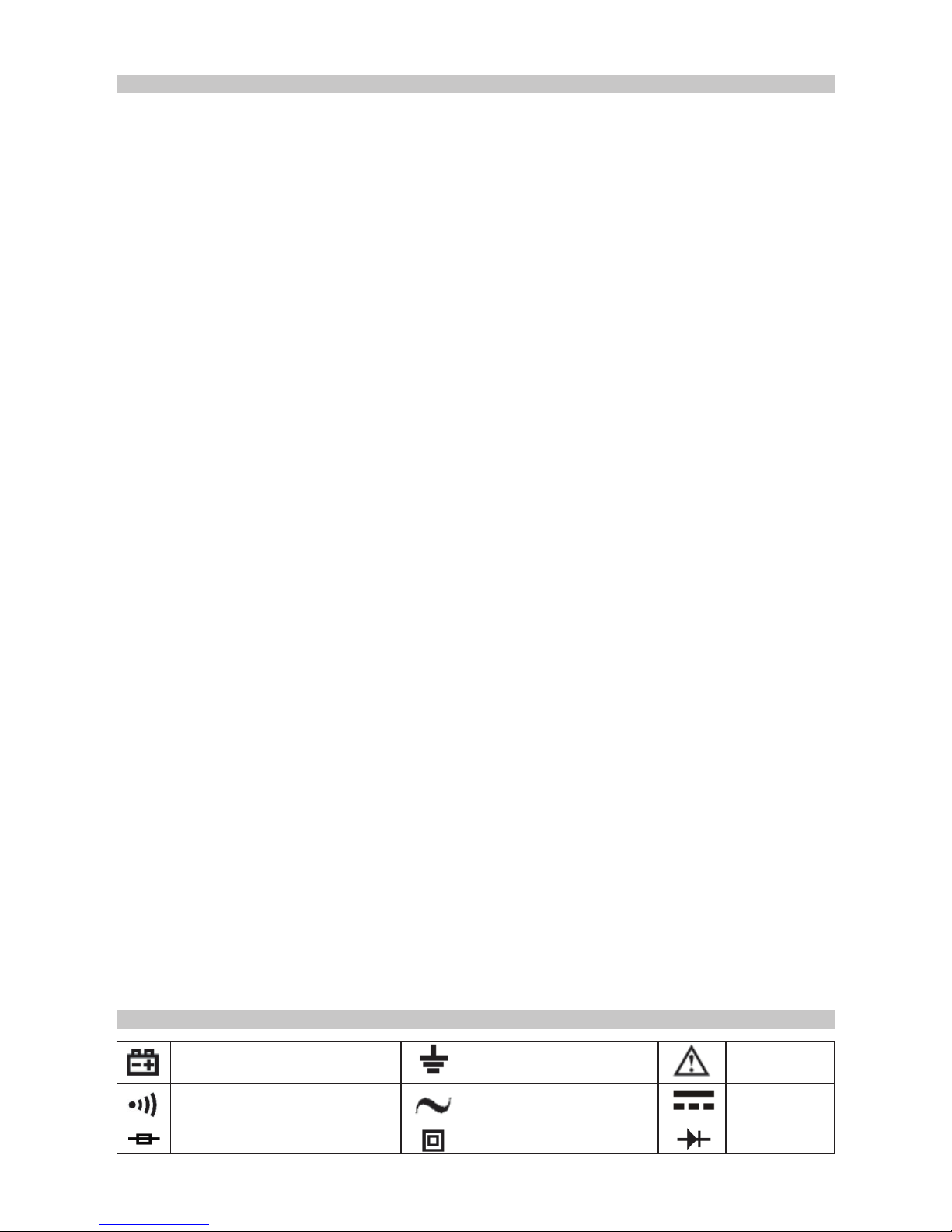
SYMBOL GUIDE
Low battery Grounding Warning
Continuity Buzzer AC DC
Fuse Double insulated Diode
IMPORTANT SAFETY INFORMATION
Page 3
3
WHAT’S INCLUDED
• Digital multimeter
• User manual
• Set of test leads
• K-type temperature probe (72-10405 & 72-2610 only)
• 9V battery (installed)
• RS232 PC interface cable
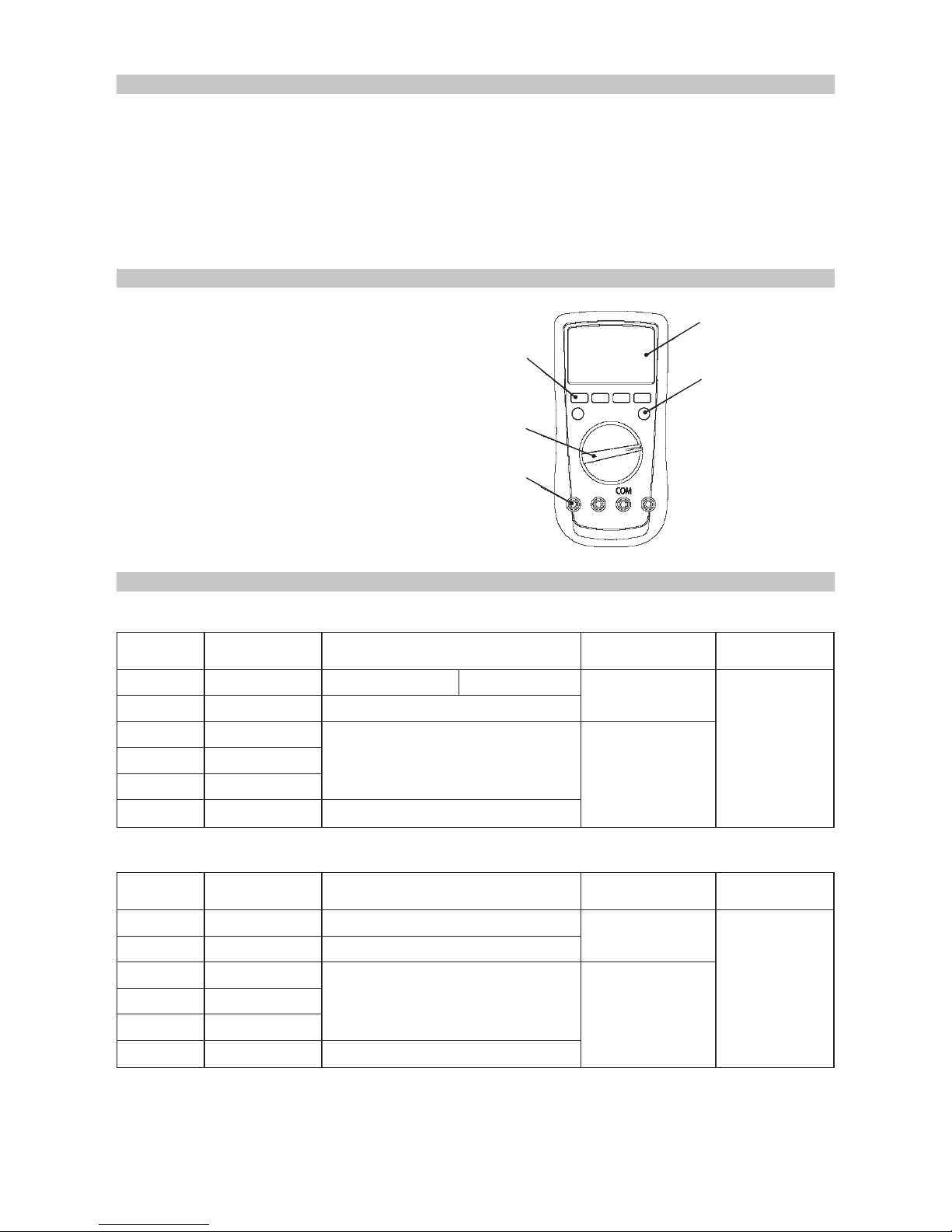
FUNCTIONS
1. LCD Display
2. FUNCTION buttons
3. BLUE button
4. Range selector
5. Input terminals
DC VOLTAGE
Range Resolution 72-2605 Accuracy 72-10405
Input
Impedance
Fixed value
input
40mV 0.01mV ±(0.8%+3)
Around
>3000MΩ
1000V DC
750V AC
400mV 0.1mV ±(0.8%+3)
4V 0.001V
±(0.5%+1)
Around 10MΩ
40V 0.01V
400V 0.1V
1000V 1V ±(1.0%+3)
Range Resolution 72-2610 Accuracy 72-10410
Input
Impedance
Fixed value
input
60mV 0.01mV ±(0.8%+3)
Around
>3000MΩ
1000V DC
750V AC
600mV 0.1mV ±(0.8%+3)
6V 0.001V
±(0.5%+1)
Around 10MΩ
60V 0.01V
600V 0.1V
1000V 1V ±(1.0%+3)
1
2
3
4
5
72-2605 AND 72-10405
72-2610 AND 72-10410
Page 4
4
AC VOLTAGE
Range Resolution 72-2610 Accuracy
Input
Impedance
Fixed value
input
220mV 0.01mV ±(0.1%+5)
Around
>3000MΩ
1000V DC
750V AC
2.2V 0.0001V
±(0.1%+2)
Around 10MΩ
22V 0.001V
220V 0.01V
1000V 0.1V ±(0.1%+5)
Range Resolution
Accuracy
45~1kHz >1kHz~10kHz
Input
Impedance
Fixed value
input
220mV 0.01mV ±(1.0%+10) ±(1.5%+50)
Around
>3000MΩ
1000V DC
750V AC
2.2V 0.0001V
±(0.8%+10)
±(1.2%+50)
Around 10MΩ
22V 0.001V
220V 0.01V ±(2.0%+50)
750V 0.1V ±(1.2%+10) ±(3.0%+10)
72-10415
72-10415
72-2605 and 72-10405
Range Resolution 72-2605 Accuracy 72-10405
Input
Impedance
Fixed value
input
40mV 0.01mV ±(1.2%+5)
Around
>3000MΩ
1000V DC
750V AC
400mV 0.1mV ±(1.2%+5)
4V 0.001V
±(1.0%+3)
Around 10MΩ
40V 0.01V
400V 0.1V
750V 1V ±(1.2%+5)
Range Resolution 72-2610 Accuracy 45~1kHz
Input
Impedance
Fixed value
input
60mV 0.01mV
±(1.2%+5)
Around
>3000MΩ
1000V DC
750V AC
600mV 0.1mV
6V 0.001V
±(1.0%+3)
Around 10MΩ
60V 0.01V
600V 0.1V
750V 1V ±(1.2%+5)
72-2610 and 72-10410
• Displays effective value of sine wave. mV range is applicable from 5% of range to
100% of range.
• Displays effective value of sine wave. mV range is applicable from 5% of range to
100% of range.
• True RMS is applicable from 10% of range to 100% of range.
• AC crest factor can be up to 3.0 except 1000V when it is 1.5.
• A residual reading of 10 digits with test leads shorted will not affect stated.
Page 5
5
DC CURRENT
Range Resoluon Accuracy Overload Protecon
400μA 0.1μA
±(1.0%+2)
Fuse 1 F600mA H 1000V
6.35 dia x 31.8mm
4000μA 1μA
40mA 0.01mA
±(1.2%+3)
400mA 0.1mA
4A 0.001A
±(1.5%+3)
Fuse 2 F10A H 1000V
10.3 dia x 38.1mm
10A 0.01A
Range Resoluon Accuracy Overload Protecon
600μA 0.1μA
±(1.0%+3)
Fuse 1 F600mA H 1000V
6.35 dia x 31.8mm
6000μA 1μA
60mA 0.01mA
600mA 0.1mA
6A 0.001A
±(1.2%+5)
Fuse 2 F10A H 1000V
10.3 dia x 38.1mm
10A 0.01A
Range Resoluon Accuracy Overload Protecon
220μA 0.01μA
±(0.5%+10)
Fuse 1 F600mA H 1000V
6.35 dia x 31.8mm
2200μA 0.1μA
22mA 0.001mA
220mA 0.01mA
10A 0.001A ±(1.2%+50)
Fuse 2 F10A H 1000V
10.3 dia x 38.1mm
72-2605 and 72-10405
72-2610 and 72-10410
72-10415
• When <5A continuous measurement is allowed/
• When >5A use 10 seconds measurement at an interval of more than 15 minutes.
• When <5A continuous measurement is allowed/
• When >5A use 10 seconds measurement at an interval of more than 15 minutes.
• When <5A continuous measurement is allowed/
• When >5A use 10 seconds measurement at an interval of more than 15 minutes.
Page 6
6
AC CURRENT
Range Resoluon Accuracy
Overload Protecon
400μA 0.1μA
±(1.2%+5)
Fuse 1 F600mA H 1000V
6.35 dia x 31.8mm
4000μA 1μA
40mA 0.01mA
±(1.5%+5)
400mA 0.1mA
4A 0.001A
±(2.0%+5)
Fuse 2 F10A H 1000V
10.3 dia x 38.1mm
10A 0.01A
Range Resoluon Accuracy
Overload Protecon
600μA 0.1μA
±(1.2%+5)
Fuse 1 F600mA H 1000V
6.35 dia x 31.8mm
6000μA 1μA
60mA 0.01mA
±(1.5%+5)
600mA 0.1mA
6A 0.001A
±(2.0%+5)
Fuse 2 F10A H 1000V
10.3 dia x 38.1mm
10A 0.01A
Range Resoluon
Accuracy
Overload Protecon
45~1kHz >1kHz~10kHz
220μA 0.01μA
±(0.8%+10) ±(1.2%+50)
Fuse 1 F600mA H 1000V
6.35 dia x 31.8mm
2200μA 0.1μA
22mA 0.001mA
±(1.2%+10) ±(1.5%+50)
220mA 0.01mA
10A 0.001A ±(1.5%+10)
>1kHz~5kHz
Fuse 2 F10A H 1000V
10.3 dia x 38.1mm
(2.0%+50)
72-2605 and 72-10405
72-2610 and 72-10410
72-10415
• When <5A continuous measurement is allowed.
• When >5A use 10 seconds measurement at an interval of more than 15 minutes.
• True RMS is applicable from 10% of range to 100% of range.
• AC crest factor can be up to 3.0 except 1000V where it is 1.5.
• A residual reading of 10 digits with test leads shorted will not effect stated.
• When <5A continuous measurement is allowed.
• When >5A use 10 seconds measurement at an interval of more than 15 minutes.
• Displays effective value of sine wave.
• When <5A continuous measurement is allowed.
• When >5A use 10 seconds measurement at an interval of more than 15 minutes.
• Displays effective value of sine wave.
Page 7
7
RESISTANCE
CAPACITANCE
Range Resoluon Accuracy
Overload Protecon
400Ω 0.1Ω ±(1.2%+2)
1000V DC
750V AC
4kΩ 0.001kΩ
±(1.0%+2)40kΩ 0.01kΩ
400kΩ 0.1kΩ
4MΩ 0.001MΩ ±(1.2%+2)
40MΩ 0.01MΩ ±(1.5%+2)
Range Resoluon Accuracy
Overload Protecon
600Ω 0.1Ω ±(1.2%+2)
1000V DC
750V AC
6kΩ 0.001kΩ
±(1.0%+2)60kΩ 0.01kΩ
600kΩ 0.1kΩ
6MΩ 0.001MΩ ±(1.2%+2)
60MΩ 0.01MΩ ±(1.5%+2)
Range Resoluon Accuracy
Overload Protecon
220Ω 0.01Ω
±(0.5%+10)
1000V DC
750V AC
2.2KΩ 0.0001kΩ
22KΩ 0.001kΩ
220KΩ 0.01kΩ
2.2MΩ 0.001MΩ ±(1.5%+10)
22MΩ 0.001MΩ ±(1.5%+10)
220MΩ 0.01MΩ ±(3.0%+50)
Range Resoluon Accuracy
Overload Protecon
40nF 0.01nF
±(3.0%+5)
1000V DC
750V AC
400nF 0.1nF
4µF 0.001µF
40µF 0.01µF
400µF 0.1µF ±(4.0%+5)
4000µF 1µF Unspecied
72-2605 and 72-10405
72-2605 and 72-10405
72-2610 and 72-10410
72-10415
Note: When measuring below 2kΩ, apply REL▲ to ensure measurement accuracy.
Note: When measuring below 2kΩ, apply REL▲ to ensure measurement accuracy.
Note: When measuring below 2kΩ, apply REL▲ to ensure measurement accuracy.
Note: There is around 10nF residual reading when the circuit is open.
Page 8
8
FREQUENCY
72-2610 and 72-10410
72-10415
Range Resoluon Accuracy
Overload Protecon
40nF 0.01nF
±(3.0%+5)
1000V DC
750V AC
400nF 0.1nF
4µF 0.001µF
40µF 0.01µF
400µF 0.1µF ±(4.0%+5)
4000µF 1µF Unspecied
Range Resoluon Accuracy
Overload Protecon
22nF 0.001nF
±(3.0%+5)
1000V DC
750V AC
220nF 0.01nF
2.2µF 0.0001µF
22µF 0.001µF
220µF 0.01µF
±(4.0%+5)
2.2mF 0.0001mF
22mF 0.001mF
Unspecied
220mF 0.01mF
Note: There is around 10nF residual reading when the circuit is open.
Note: There is around 1nF residual reading when the circuit is open.
To measure a small value of capacitance, use RE to ensure accuracy.
• Overload protection 100V DC / 750V AC.
• Input amplitude: DC electric level is zero.
72-2605, 72-10405, 72-2610 , 72-10410:
When 10Hz~10MHz: 200mV ≤ a ≤ 30Vrms.
72-10415: When 10Hz~10MHz: 300mV ≤ a ≤ 30Vrms.
When >10Hz~40MHz: 1V ≤ a ≤ 30Vrms.
When >40MHz: unspecied.
• When measuring on line frequency or duty cycle under AC voltage and current
measurement mote, the input amplitude and frequency response must satisfy the
following requirement:
• Input amplitude ≥range x 30%.
• Frequency response: 72-2605 and 72-10405 ≤400Hz.
72-2610, 72-10410 and 72-10415 ≤1kHz.
Model Range Accuracy Max Resoluon
72-2605/72-10405/
72-2610/72-10410
10Hz~10MHz (0.1%+4) 0.01Hz
72-10415 10Hz~220MHz (0.01%+5) 0.001Hz
Page 9
9
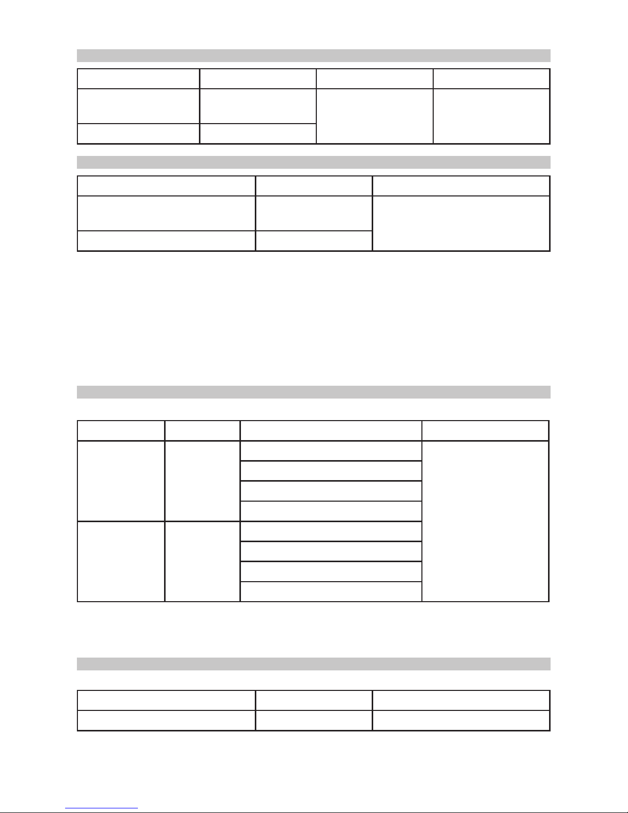
DIODE TEST
CONTINUITY TEST
TEMPERATURE MEASUREMENT
TRANSISTOR TESTING
72-10405 AND 72-2610 ONLY
72-2605 ONLY
Model Resoluon Notes Overload Protecon
72-2605/72-10405/
72-2610/72-10410
0.001V
Open circuit voltage
around 2.8V
1000V DC
750V AC
72-10415 0.0001V
Range Resoluon Accuracy Overload Protecon
o
C 1oC
(-40oC~-20oC):-(8%+5)
1000V DC
750V AC
(>-20oC~0oC): ±(1.2%+4)
(>0oC~100oC): ±(1.2%+3)
(>100oC~1000oC): ±(2.5%+2)
o
F
1oF
(-40oF~4oF):-(8%+6)
(>4oF~32oF): ±(1.2%+5)
(>32oF~212oF): ±(1.2%+4)
(>212oF~1832oF): ±(2.5%+3)
Model Resoluon Overload Protecon
72-2605/72-10405/
72-2610/72-10410
0.1Ω
1000V DC
750V AC
72-10415 0.01Ω
Range Resoluon Notes
hFE 1ß lbo = 10µA 1000ß Max
• 72-2605, 72-10405, 72-2610, 72-10410:
Open circuit voltage is around 0.45V.
Broken circuit resistance value is around >35Ω the buzzer does not sound.
Good circuit resistance value is ≤10Ω the buzzer sounds continuously.
• 72-10415:
Open circuit voltage is around -3V.
Broken circuit resistance value is around >30Ω the buzzer does not sound.
Good circuit resistance value is ≤10Ω the buzzer sounds continuously.
Thermocouple
Use K type thermocouple. The included point type contact K type thermocouple can
only be used on less than 230oC temperature measurements.
Page 10
10
OPERATION
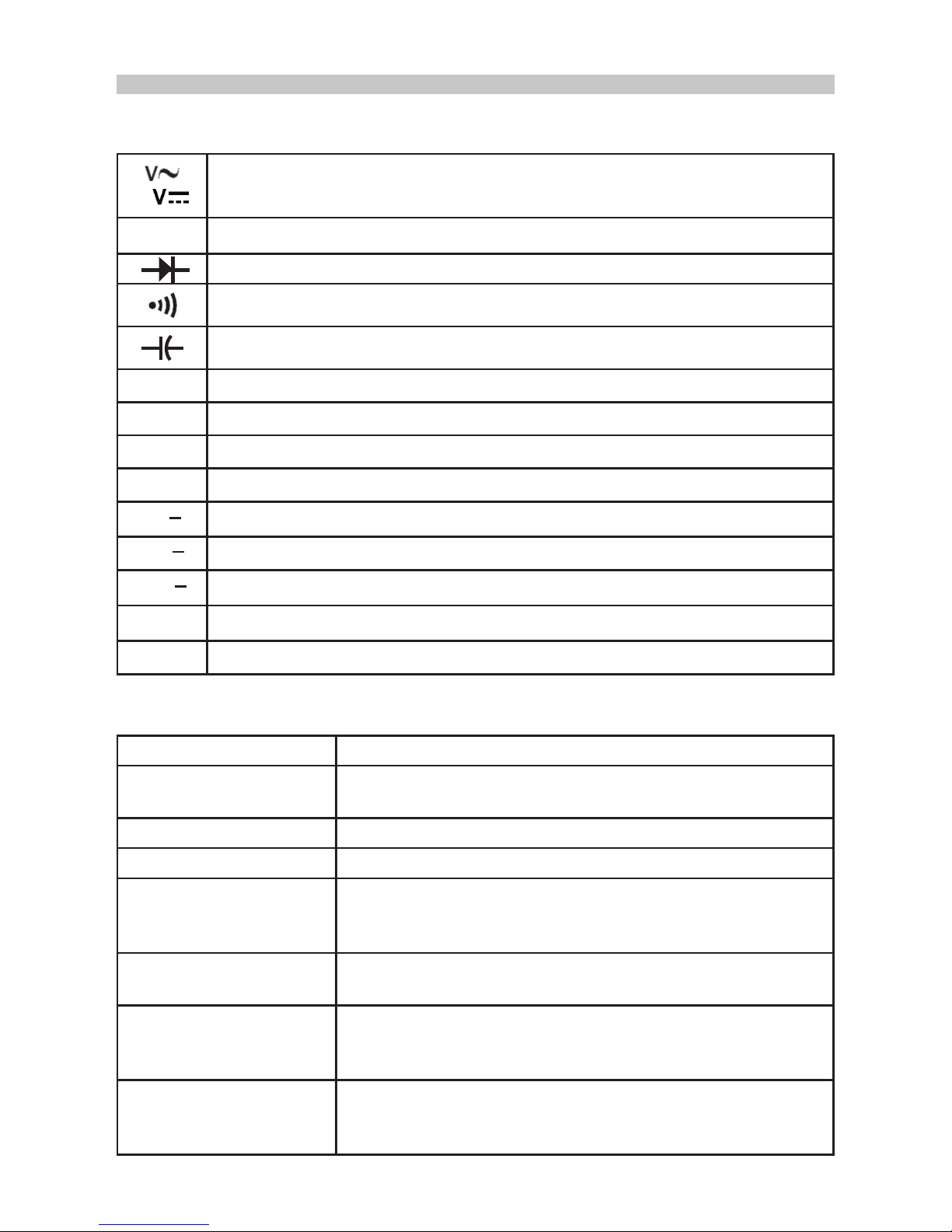
Rotary Switch
Below table indicates the rotary selector switch position functions.
Function Buttons
Below table indicates the operation of the function buttons.
m
AC and DC Voltage measurement
Ω
Resistance measurement
Diode test
Continuity test (sounder)
Capacitance test
Hz %
Frequency and duty cycle test
o
C
Temperature in Celsius
o
F
Temperature in Fahrenheit
hFE
Transistor test
µA
~
DCA and ACA measurement
mA
~
DCmA and ACmA measurement
10A
~
10A DC and AC measurement
EF
Sensor test (72-2605 only)
OFF
Power off
Button Operation
Light (72-2605, 72-10405
72-2610 & 72-10410)
Press and hold for 2 sec to turn backlight on or off
Hold Press to enter or exit data hold mode
BLUE button Press to select the alternate feature
RANGE Press RANGE to enter the manual ranging mode
Press RANGE to step through the ranges available
Press and hold RANGE for 2 secs to return to autoranging
MAX/MIN
(72-2605,
72-
10405, 72-2610 & 72-10410)
Press to select maximum and minimum value.
REL▲ Press to enter REL mode and again to exit REL mode
For Model 72-10405, 72-2610 Press and hold for over 2
seconds to enter or exit RS232C or USB mode.
PEAK (72-10415 only) Press to step through Pmax and Pmin readings
Press and hold for 2 secs to exit peak mode
CAL enters the self calibration mode
Page 11
11
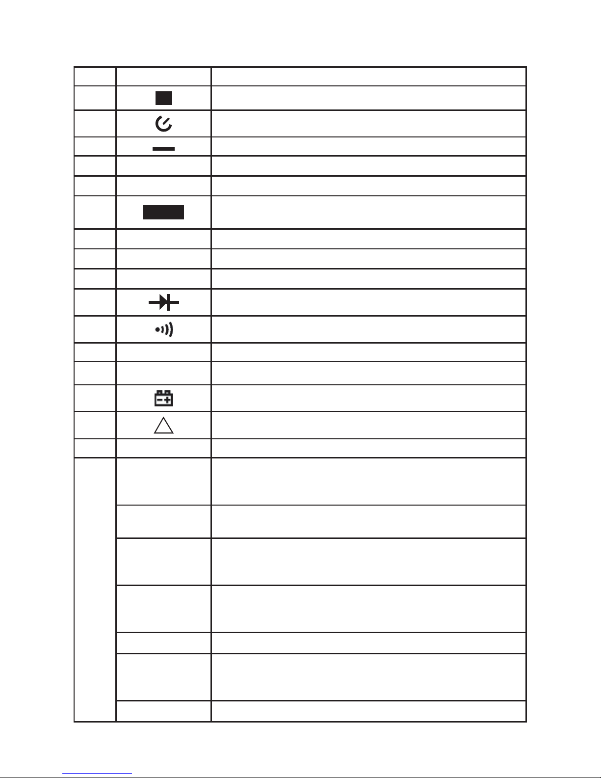
Display symbols
No Symbol Meaning
1
H
Data hold is active.
2 Sleep Mode indicator
3 Indicates negative reading.
4
AC
Indicator for AC measurement
5
DC
Indicator for DC measurement
6
AUTO
The Meter is in the auto range mode in which the Meter
automatically selects the range with the best resolution.
7
MANU
Indicator for manual ranging mode.
8
OL
The input value is too large for the selected range.
9
hFE
Transistor testing indicator
10 Diode test
11 Continuity buzzer on
12 MAX/MIN Maximum and Minimum reading.
13
S
Data output is in progress
14 The battery is low.
15
EF
Sensor test is in progress
16 ▲ REL is on to display stored value minus present value
17
Ω, kΩ, MΩ
Ohm unit of resistance
Kilohm 1x10³ or 1,000ohms
Megaohm 1x10⁶ or 1,000,000ohms
V, mV
Volts unit of voltage
Millivolt 1x10⁻³ or 0.001volts
µA, mA, A
Amperes unit of current
Milliamp 1x10⁻³ or 0.001amperes
Microamp 1x10⁻⁶ or 0.000001amperes
nF, µF, mF
Farad unit of capacitance
Microfarad 1x10⁻⁶ or 0.000001farads
Nanofarad 1x10⁻⁹ or 0.000000001farads
o
C, oF
Centigrade or Fahrenheit unit of temperature
Hz, kHz, MHz
Hertz unit of frequency in cycles per second
Kilohertz 1x10³ or 1,000Hertz
Megahertz 1x10⁶ or 1,000,000Herts
ß
Unit of transistor
Page 12

12
Hold Mode
• The Hold mode is applicable to all measurement functions.
• Press HOLD to enter Hold mode; the meter buzzer sounds.
• Press HOLD again to exit Hold mode; the meter buzzer sounds.
• In Hold mode, H is displayed.
Note: To avoid possibility of electric shock, do not use Hold mode to determine if
circuits are without power. The Hold mode will not capture unstable or noisy readings.
Range button
• Press RANGE to enter the manual ranging mode; the Meter buzzer will sound.
• Press RANGE to step through the ranges available for the selected function; the
Meter buzzer will sound.
• Press and hold RANGE for over 2 seconds to return to autoranging; the Meter
buzzer will sound.
MAX MIN button 72-2605,72-10405 and 72-2610, 72-10410 only
• Press MAX MIN to start recording of maximum and minimum values. Steps the
display through high (MAX) and low (MIN) readings. The Meter enters manual
ranging mode after pressing MAX MIN button.
• Press and hold MAX MIN for over 2 seconds to exit MAX MIN mode and return to
the active measurement range.
Peak Hold 72-10415 only
• Under voltage and current measurement mode, press the PEAK button to enter
manual ranging mode and start recording of Pmax and Pmin values. The LCD
displays MANU/Pmax.
• Press PEAK again to display MANU/Pmin.
• Press PEAK to step the display through Peak Max and Peak Min readings.
• Press and hold PEAK for over 2 seconds to exit Peak mode, the LCD displays the
present measurement values.
• Don’t press the “PEAK” Key. If the meter has entered “CAL” mode.
Data Output all except 72-10405, 72-10415 and 72-2610, 72-10410 only
• Press and hold REL button for over 2 seconds to enter or exit RS232C or USB
mode.
• The sleep mode feature will be disabled after entering RS232C or USB modes, the
on the LCD will disappear (72-10405,72-10410 and 72-2610 only).
• If the meter is performing HOLD, MAX MIN or REL measurement, the LCD will
display the corresponding readings but the interface output will still be the random
value of the present input terminal measurement.
Using Relative Value mode
• The REL mode applies to all measurement functions except frequency/duty cycle
measurement. It subtracts a stored value from the present measurement value
and displays the result.
• Press REL▲ to enter REL mode and the present measurement range is locked
and display shows “0” as the stored value.
• Press REL again to reset the stored value and exit the REL mode.
Page 13
13
The BLUE button
• This is used to select the required measurement function when there is more than
one function option within one position on the rotary control setting.
Turning on the display backlight 72-2605, 72-10405 and 72-2610 only.
• Use to avoid mistaken readings in insufcient lighting or poor vision applications.
• Press and hold HOLD/LIGHT for over 2 seconds to turn the display backlight on.
• The backlight will automatically switch off after around 10 seconds.
Sleep mode
• To preserve battery life the meter will automatically power off if you do not move
the rotary switch or press any button for around 15 minutes.
• The meter re-activates by pressing any button or turning the rotary switch.
• To disable the sleep function press and hold the BLUE button while turning on the
meter.
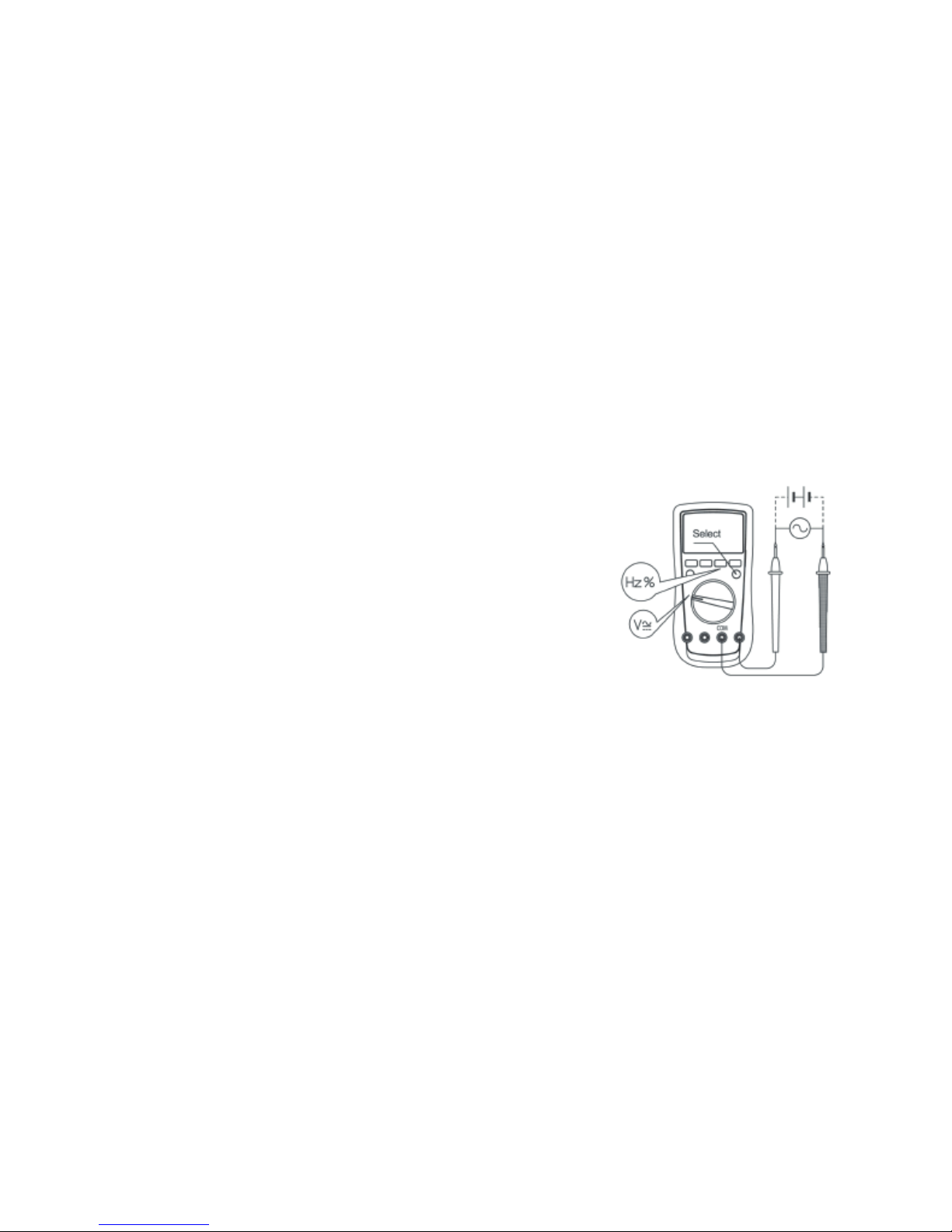
Measuring Voltage
• Insert the red test lead into the V terminal and the black test lead into COM.
• Set the rotary selector to V, DC measurement is default.
• Press the BLUE button to switch between AC and DC
modes.
• Connect the test leads across the object to be measured
and the value will be displayed.
Notes
• In each range, the Meter has an input impedance of
10MΩ except mV range which input impedance is
3000MΩ. This loading effect can cause measurement
errors in high impedance circuits. If the circuit
impedance is less than or equal to 10kΩ, the error is negligible (0.1% or less).
• For 72-2605 : When measuring mV, you must press RANGE manually to enter mV
range.
• When voltage measurement has been completed, disconnect the connection
between the testing leads and the circuit under test, and remove the testing leads
away from the input terminals of the Meter.
Page 14
14
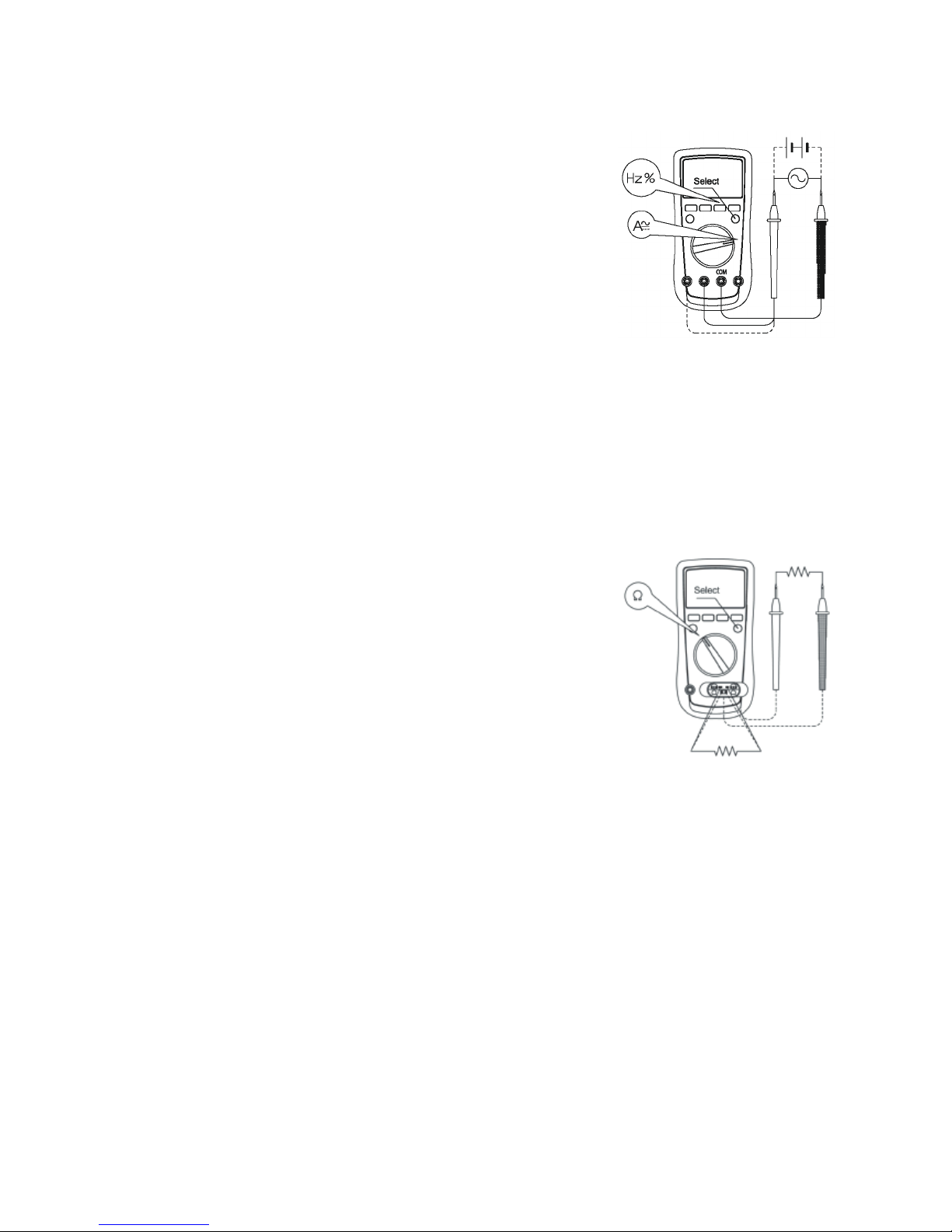
Measuring Current
• Insert the red test lead into the mA or A input terminal and the black test lead into
the COM terminal.
• Set the rotary switch to µA, mA, or A.
• The Meter defaults to DC current measurement mode.
To switch between DC and AC current measurement
function, press the BLUE button.
• Connect the test lead in serial to the circuit to be tested.
The measured value shows on the display.
• 72-2605,72-10405 and 72-2610: displays effective value
of sine wave (mean value response).
• 72-10415: displays the true rms value.
Notes:
• If the current to be measured is unknown, choose the maximum measuring range
and reduce it step by step until a satisfactory reading is obtained.
• Disconnect from the circuit under test when changing the range.
• If the display only shows “OL”, it indicates the measured current is out of range. In
this case, turn the range selector to a higher range.
• For safety, each measurement time for >5A current should be less than 10
seconds and the interval time between 2 measurements should be greater than 15
minutes.
Measuring Resistance
• Insert the red test lead into the Ω terminal and the black
test lead into the COM terminal.
• Set the rotary switch to Ω resistance measurement (Ω) is
default or press BLUE button to select Ω measurement
mode.
• Connect the test leads across with the object being
measured. If there is lead on the resistor or SMT
resistor, it is more convenience to use the included multipurpose socket to carry out testing. The measured value
shows on the display.
Warning
To avoid damages to the Meter or to the devices under test, disconnect circuit power
and discharge all the high-voltage capacitors before measuring resistance.
To avoid harm to yourself, do not input higher than DC 60V or AC 30V voltages.
Notes
The test leads can add 0.2Ω to 0.5Ω of error so to obtain precision readings, short
circuit the terminals and use REL measurement function to automatically subtract the
short circuit value from the reading measured.
For high resistance measurement >1MΩ, it is normal for it to take several seconds to
obtain a stable reading.
The display will show OL if the tested resistance is greater than the maximum range of
the meter.
• When resistance measurement has been completed, disconnect the connection
between the testing leads and the circuit under test, and remove the testing leads
away from the input terminals of the Meter.
Page 15
15
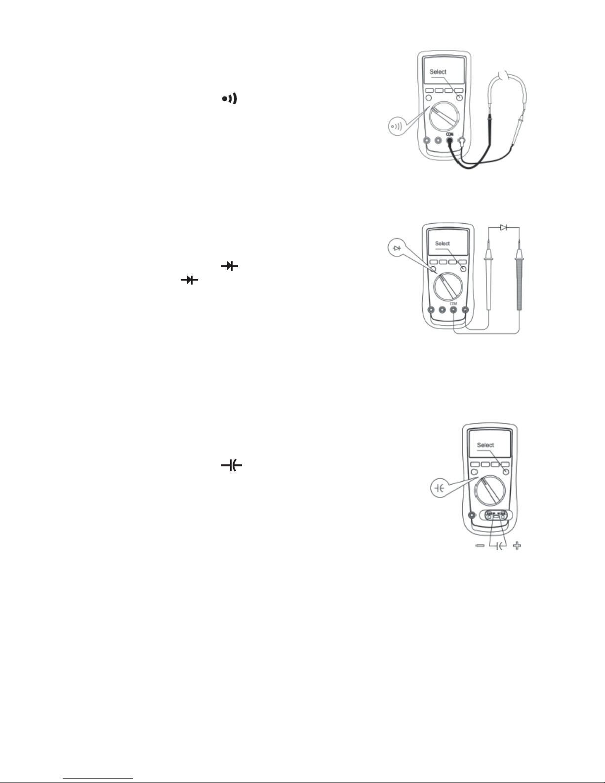
Testing for continuity
• Insert the red test lead into the Ω terminal and the
black test lead into the COM terminal.
• Set the rotary switch to terminal.
• The buzzer sounds continuously if the resistor to be
tested is <10Ω
• The buzzer does not sound if the resistor to be tested
is >35Ω
• When continuity testing has been completed,
disconnect the connection between the testing leads and the circuit under test,
and remove the testing leads away from the input terminals of the Meter.
Testing Diodes
• Insert the red test lead into the Ω terminal and the black
test lead into the COM terminal.
• Set the rotary switch to terminal and press BLUE
button to select measurement.
• For forward voltage drop readings on any
semiconductor component place the red test lead on
the anode and the black test lead onto the cathode.
• The measured value shows on the display.
• When diode testing has been completed, disconnect the connection between the
testing leads and the item under test, and remove the testing leads away from the
input terminals of the Meter.
Note: A good diode should produce a forward voltage drop of 0.5V to 0.8V.
Capacitance measurement
• Insert the red test lead into the Ω terminal and the black test lead
into the COM terminal.
• Set the rotary switch to terminal and press BLUE button to
select nF measurement.
• The Meter will display a xed value as below which is the
Meters internal xed distributed capacitance value. To ensure
accuracy when measuring a small value of capacitance, use
REL to subtract this from the tested value.
• Connect the test leads across the object being measured.
• 72-2605, 72-10405, 72-2610 and 72-10415: is around 10nF
72-10415: is around 1nF.
• Alternatively, use the included multi-purpose socket for measuring capacitors with
leads or SMT capacitor. Insert the capacitor to be tested into the corresponding
“+” and “-” jack of the multi-purpose socket. This method is more stable and
suitable for small value of capacitance testing.
• OL is displayed if the tested capacitor is shorted or exceeds the maximum range.
• When capacitance testing has been completed, disconnect the connection
between the testing leads and the item under test, and remove the testing leads
away from the input terminals of the Meter.
Page 16
16
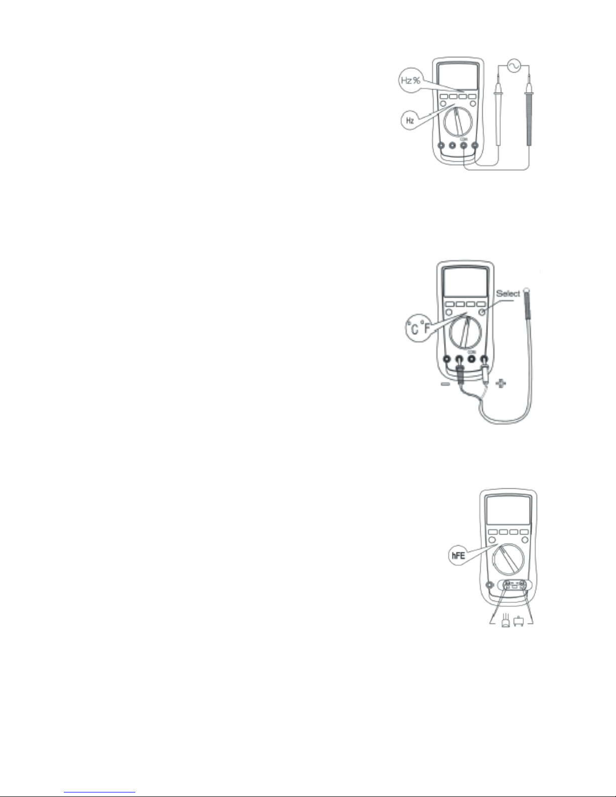
Transistor hFE Measurement 72-2605 only
• Set the rotary switch to hFE.
• Insert the multi-purpose socket into the input terminal as shown
on gure 10.
• Insert the transistor to be tested into the corresponding multipurpose socket jacks.
• The LCD display hFE nearest value.
• When transistor measurement has been completed, disconnect
all the connection between multi-purpose socket, transistor and
the Meter.
Frequency measurement
• Insert the red test lead into the Hz terminal and the black
test lead into the COM terminal.
• Set the rotary switch to Hz% frequency measurement
• Hz is default or press Hz% button to select Hz
measurement mode.
• Connect the test leads across the object being measured
and the value shows on the display.
• If you need to measure the duty cycle, press Hz% button
to select % measurement mode.
• When frequency measurement has been completed, disconnect the connection
between the testing leads and the circuit under test, and remove the testing leads
away from the input terminals of the Meter.
Temperature measurement 72-10405 and 72-2610 only
• Set the rotary switch to Co F
o
• Insert the temperature probe into the input terminal as
shown:
• Place the temperature probe to the object being
measured.
• After few seconds, the measured value shows on the
display.
• Press BLUE button to toggle between Co and Fo options.
Note To avoid measurement error especially low
temperature measurement, the ambient operating
temperature must not exceed 18oC~28oC.
• When temperature measurement has been completed,
disconnect the temperature probe from the object being measured, and remove
the temperature probe from the input terminals of the Meter.
Page 17
17
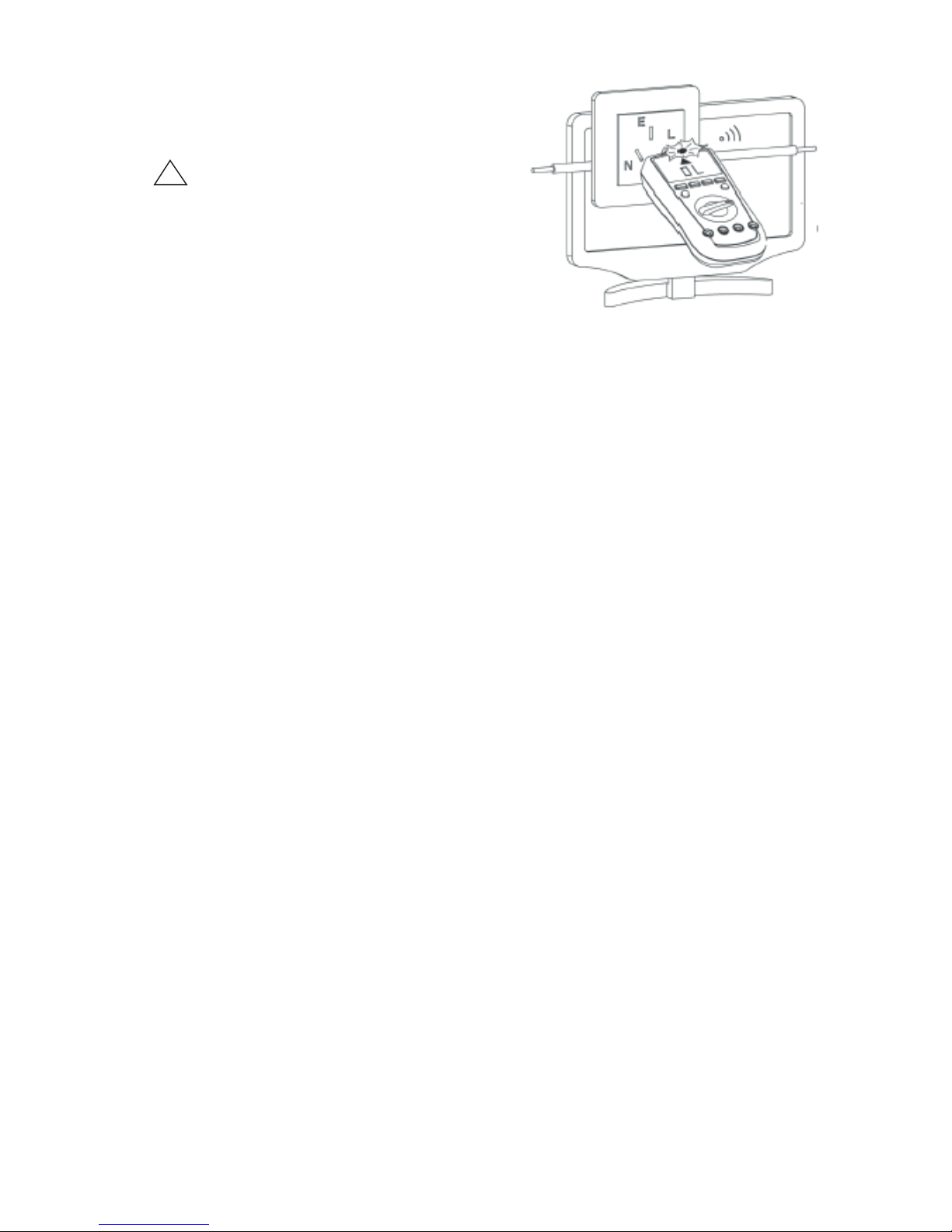
EF Function 72-2605 only
• Set the rotary switch to EF and remove any
test leads from the input terminals.
• Place the housing front part with marking
EF
toward the source of EF.
• There will be three types of displays:
• LCD displays shows the strength of detected
signal.
• When the LCD displays OL, the buzzer
sounds and the red LED ashes.
Page 18
18
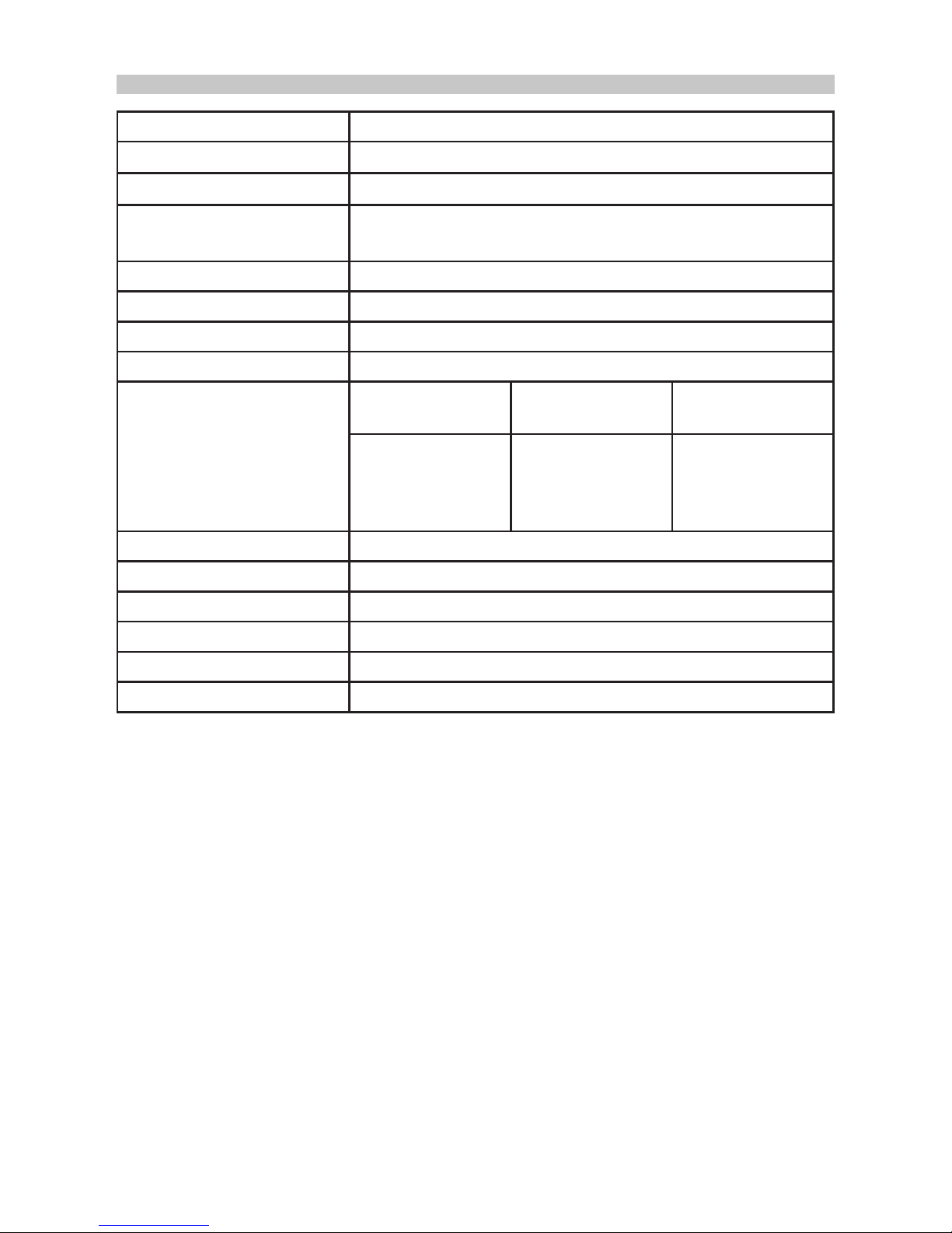
SPECIFICATIONS
Function Range/description
Operating Temperature
0o~40oC (32oF~104oF)
Storage Temperature
-10oC~50oC (14oF~122oF)
Relative Humidity
≤75%@ 0oC~30oC below
≤50%@ 30oC~40oC
Battery Type 9V NEDA 1604 or 6F22 or 006P
Range Auto or manual
Polarity Auto
Measurement speed Updates 2-3 times/second
Analogue bar graph 72-2605 and
72-10405
72-2610 72-10415
41 segments,
max reading
4000
(frequency 9999)
61 segments,
max reading
6000
(frequency 9999)
46 segments,
max reading
22000
(frequency 9999)
DC Voltage 0 to 1000V
DC Current 0 to 10A (5~10A for ≤10 seconds, interval ≥15 minutes)
AC Voltage 0 to 750V
AC Current 0 to 10A (5~10A for ≤10 seconds, interval ≥15 minutes)
Dimensions (H x W x L) 180 x 87 x 47mm
Weight 370g incl battery
Page 19
19
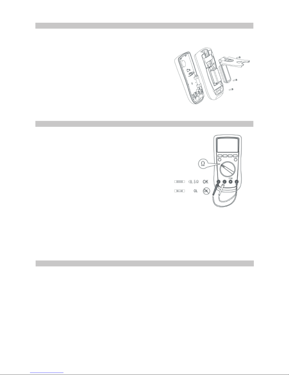
BATTERY REPLACEMENT
Warning: Only replace the battery after the test leads are removed and the power is
turned off.
To replace the battery,
• Remove the screw from the tilt stand and the
battery cover and separate the battery cover and
the tilt stand from the case bottom.
• Remove the battery from the battery
compartment.
• Replace the battery with a new 9V battery
(NEDA1604, 6F22 or 006P)
• Ret the tilt stand and battery cover to the case
bottom, and reinstall the screw.
To replace the fuses,
• Turn the Meter power off and remove all the
connections from the terminals.
• Remove the screw from the tilt stand and the
battery cover and separate the tilt stand from the
case bottom half.
• Remove the two screws from the case bottom,
and separate the case halves.
• Remove the fuse by gently prying one end loose,
then take out the fuse from its holder.
• Install ONLY replacement fuses with the identical type and specication as follows
and make sure the fuse is xed rmly in the holder.
A mA range: F1, 600mA H 1000V, 6.35x31.8mm
10A range: F2, 10A H 1000V, 10.3 x 38.1mm
• Ret the case bottom to the case top, and reinstall the screw.
• Ret the tilt stand, battery compartment and case bottom, and reinstall the screw.
FUSE REPLACEMENT
If the Meter does not response when measuring current
and transistor hFE, test to see if a fuse has blown as shown:
• Clean the meter with a clean, soft cloth.
• Do not use any chemicals, abrasives or solvents that could damage the meter.
CLEANING
Page 20

20
INFORMATION ON WASTE DISPOSAL FOR CONSUMERS OF
ELECTRICAL & ELECTRONIC EQUIPMENT
These symbols indicate that separate collection of Waste Electrical and Electronic Equipment
(WEEE) or waste batteries is required. Do not dispose of these items with general household
waste. Separate for the treatment, recovery and recycling of the materials used. Waste batteries
can be returned to any waste battery recycling point which are provided by most battery retailers.
Contact your local authority for details of the battery and WEEE recycling schemes available in
your area.
Made in China. PR2 9PP
Man Rev 1.0
 Loading...