

Tenma 72-10465 Operating Manual
www.element14.com
www.farnell.com
www.newark.com
www.cpc.co.uk
TM
TM
Page <1>
V1.010/01/18
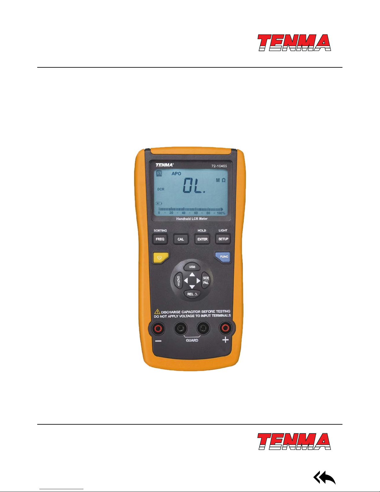
Operating Manual
72-10465 LCR Meter

www.element14.com
www.farnell.com
www.newark.com
www.cpc.co.uk
TM
TM
Page <2>
V1.010/01/18
Table of Contents
I. General Characteristics and Safety Notice . . . . . . . . . . . 3
II. Ambient Conditions . . . . . . . . . . . . . . . . . . . . . . . 3
Ill. Function Characteristics . . . . . . . . . . . . . . . . . . . . 3
IV. Impedance Parameters . . . . . . . . . . . . . . . . . . . . . 4
V. Measurement Mode . . . . . . . . . . . . . . . . . . . . . . . 4
VI. LCD Display Instructions (shown in Figure 2) . . . . . . . . . 5
VII. Instructions of key functions of 72-10465 front panel
(Shown in Figure 3) . . . . . . . . . . . . . . . . . . . . . . . 6
VIII. Operation Guideline . . . . . . . . . . . . . . . . . . . . . . . 6
IX. Fast Application Guideline . . . . . . . . . . . . . . . . . . . 9
X. PC Communication Protocol . . . . . . . . . . . . . . . . . . 11
XI. Technical Indicators . . . . . . . . . . . . . . . . . . . . . . . 11
XII. Battery Replacement . . . . . . . . . . . . . . . . . . . . . .14
XIII. Maintenance . . . . . . . . . . . . . . . . . . . . . . . . . . . 14
www.element14.com
www.farnell.com
www.newark.com
www.cpc.co.uk
TM
TM
Page <3>
V1.010/01/18
I. General Characteristics and Safety Notice
The 72-10465 LCR meter features an easy to read dual display measurement of 19999/1999. It also has serial and parallel
measurement modes which can be used to select quality factor, loss factor, phase location angle, and equivalent resistance
of measure articles. Intelligent detection and ve different test frequencies enable accurate readings for all sizes of capacitors
and inductors. The user can also access the stored data on a PC with the included USB connection and interface software.
The compact size and case make this unit far more portable than a bench top meter.
Measurement Range and Precision
L: 20mH---2000H Best accuracy (0.5% +5);
C: 200pf---20mF Best accuracy (0.5% +5);
R: 20Ω---200MΩ Best accuracy (0.3% +5);
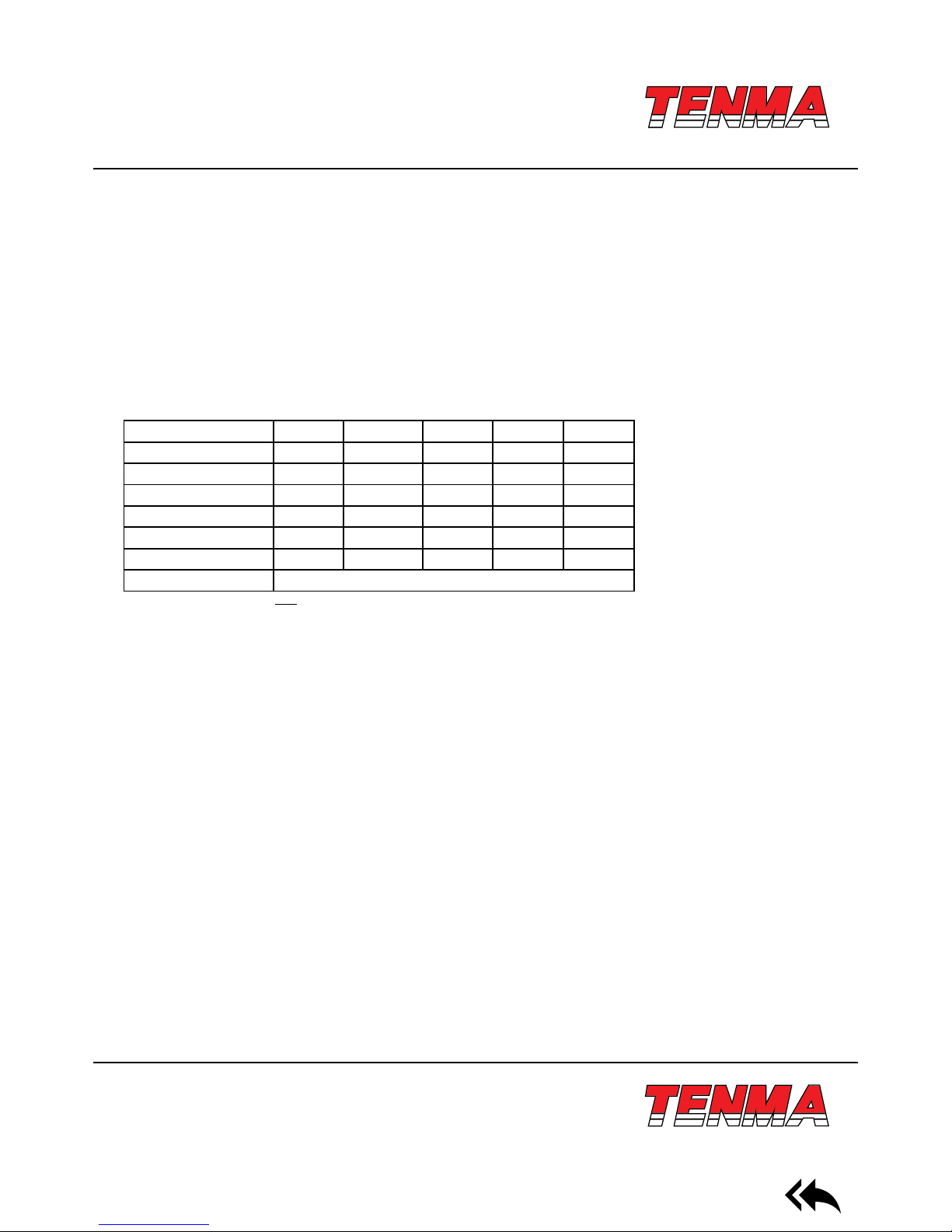
Impedance/frequency DCR 100/120Hz 1kHz 10kHz 100kHz
0.1-1 1% 1% 1% 1% 1%
1-10 0.5% 0.5% 0.5% 0.5% 0.5%
10-100k 0.3% 0.3% 0.3% 0.5% 0.3%
100k-1M 0.5% 0.5% 0.5% 1%
1M-20M 1% 1% 1%
20M-200M 2% 2% 5%
Remark D<0.1
Note: Please multiply by √1+D
2
if D exceeds 0.1
Formula to convert capacitance to impedance: Zc=1/2πfC
Formula to convert inductance to impedance: ZL=2πfL
Please abide by the following instructions to ensure safe use of the meter:
1) Do not use the meter in an extreme environment, especially dusty environments, near high radiation, or around amma-
ble substances.
2) Do not attempt to alter, repair, or calibrate the unit yourself. Such work should only be done by a trained professional or
as directed by your distributor.
3) Do not attempt to modify the meter, break insulation, or remove working parts.
4) Be certain that all circuits have been shut down and are free of voltage.
5) Do not apply any input voltage to the meter. Be sure to discharge any electried components such as capacitors.
6) This meter can be powered by two different methods. The rst is by a 9V battery, and the second is by the included USB
cable. USB will also allow the unit to sync data while it is being powered to save the life of the battery.
II. Ambient Conditions
1) Altitude: <2000 meters
2) Storage humidity: = 75% RH
3) Operating environment: 0°C ~ 40°C
4) Storage environment: -20°C ~ +50°C
Ill. Function Characteristics
1) Main display of 19,999 and auxiliary display of 1 ,999
2) Measurement frequency: 1 00Hz/120Hz/1kHz/10kHz/100kHz
www.element14.com
www.farnell.com
www.newark.com
www.cpc.co.uk
TM
TM
Page <4>
V1.010/01/18
3) Measurement voltage: 0.6Vrms
4) Output impedance: 120Ω
5) Basic precision: 0.5%
6) LCR automatic identication/manual measurement
7) Measurement of DCR DC resistance
8) Calibration compensation of open circuit/short-circuit
9) Automatic shutdown
10) Relative measurement & sieving function
11) Communication between Mini-USB and PC; Data acquisition/analysis/ statement
IV. Impedance Parameters
Impedance measurement instruments can be classied as DC impedance and AC impedance types. A general multimeter
can be used to measure DC impedance, while a bridging instrument (such as this) can be used to measure AC or DC impedance. The 72-10465 is an intelligent double-display portable LCR digital electric bridge, with DC & AC impedance measure-
ment functions. Impedance is one of the most fundamental parameters to analyze electronic elements and circuits. The
resistance of linear diode is dened by Ohm’s Law as part of a DC power scenario. Ratio of voltage and current is a complex
impedance as part of an AC power scenario. One impedance vector includes one real part (resistance R) and one imaginary
part (reactance X). Impedance is expressed by R+jX in a rectangular coordinate, or expressed by the amplitude of real Z and
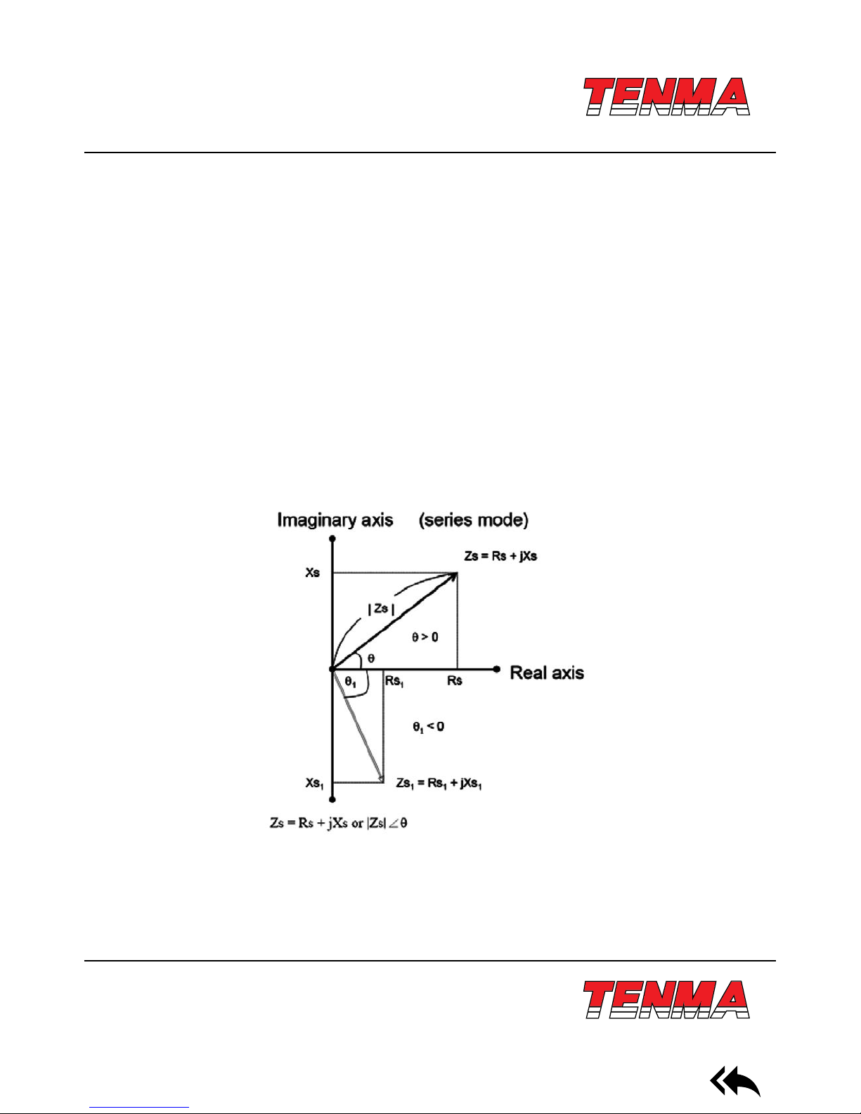
phase angle of 0 in a polar coordinate system. See gure 1-1 for relationship.
Reaction is inductive if θ exceeds 0. In other words, reaction is capacitive if θ is less than 0.
V. Measurement Mode
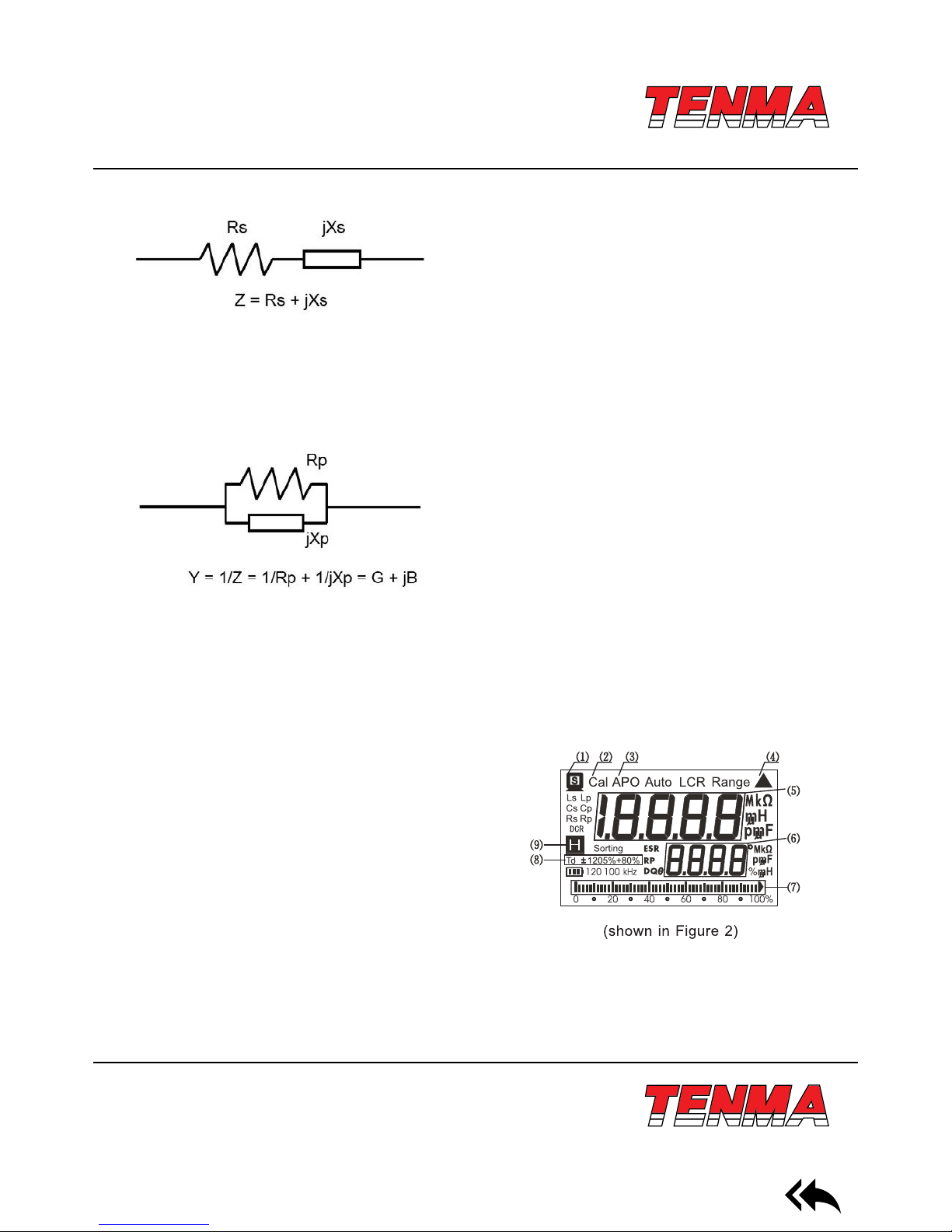
Impedance can be used to measure serial or parallel mode. Impedance of Z under parallel link mode can be expressed by
mutual access of Y. It can be dened as follows: Y= G+ JB. G is conductance and B is admittance.
Rs = IZsl cos θ
Xs = IZsI sin θ
Xs/Rs = tan θ
θ = tan
-1
(Xs/Rs)
www.element14.com
www.farnell.com
www.newark.com
www.cpc.co.uk
TM
TM
Page <5>
V1.010/01/18
Impedance under serial link mode
Rs: Serial mode of resistance
Xa: Serial mode of reaction
Cs: Serial mode of capacitance
Ls: Serial mode of inductance
Admittance parallel mode
Rp: Parallel mode of resistance
XP: Reaction under parallel mode
CP: Parallel mode of capacitance
LP: Parallel mode of inductance
VI. LCD Display Instructions (shown in Figure 2)
Main display instructions of LCD:
(1) USB communication
(2) Calibration of open circuit/short-circuit
(3) Automatic shutdown
(4) Relative measurement
(5) Main display
(6) Auxiliary display
(7) Analog bar
(8) Sieving tolerance mode
(9) Data retention
Other denitions:
1 ) LCR: Automatic identication mode
2) Lp: Parallel measurement mode for inductance
3) Ls: Serial measurement mode for inductance
4) Cp: Parallel measurement mode for capacitance
5) Cs: Serial measurement mode for capacitance
6) Rp: Parallel measurement mode for resistance
7) Rs: Serial measurement mode for resistance
 Loading...