

Tenma 72-1025 User Manual
Benchtop LCR Meter
RS232
u
u
ALWAYS DISCHARGE THE CAPACITOR BEFORE TESTING
ON
OFF
FORCE
FREQ
FORCE
HOLD
REC
RS232
SENSESENSE
L/C/R
P SAUTO
RANGE TOL
CAL
REL
Model 72-1025
Tenma Test Equipment
405 S. Pioneer Blvd.
Springboro, OH 45066
www.tenma.com
i

Contents
Safety ................................................................................................... 1
Introduction........................................................................................... 3
Impedance theory................................................................................. 4
Impedance ................................................................................ 4
Measuring impedance ............................................................... 7
Parasitic .................................................................................... 7
Real, effective, and indicated values ......................................... 8
Component dependency factors ..............................................10
Measurement methods.............................................................16
Getting Started.....................................................................................17
Front Panel Illustration .............................................................17
Rear Panel Illustration ..............................................................18
LCD Display Illustration ............................................................19
Measurement Preceedure ...................................................................21
Inductance Measurement.........................................................22
Capacitance Measurement......................................................23
Resistance Measurement.........................................................24
Operating Instructions..........................................................................25
Data Hold .................................................................................25
Static Recording™....................................................................25
Dissipation Factor / Quality Factor/ Phase Angle .....................26
Test Frequency.........................................................................26
L/C/R Function Selector ...........................................................26
Relative Mode ..........................................................................26
Tolerance Mode........................................................................27
Auto / Manual Range................................................................28
Automatic Fuse Detection ........................................................28
Parallel / Series Mode ..............................................................29
Short/ Open Calibration............................................................31
Communication ........................................................................32
General Specifications.........................................................................33
Electrical Specifications.......................................................................34
Resistance (Parallel mode) ......................................................34
Capacitance (Parallel mode) ....................................................35
Inductance (Series mode)......................................................37
ii

Accessories .........................................................................................39
Standard Accessories: ..................................................................39
Optional Accessories: ...................................................................40
MAINTENANCE ..................................................................................41
Service .....................................................................................41
Cleaning the Meter ...................................................................41
Selecting input line voltage.......................................................42
Fuse Replacement ...................................................................44
iii
SAFETY
Read "SAFETY INFORMATION" before using this meter.
NOTE
The meter is a bench type instrument for testing inductance,
capacitance and resistance. If this device is damaged or something is
missing, contact the place of purchase immediately.
This manual contains information and warnings must be followed to
ensure safe operation as well as to maintain the meter in a safe
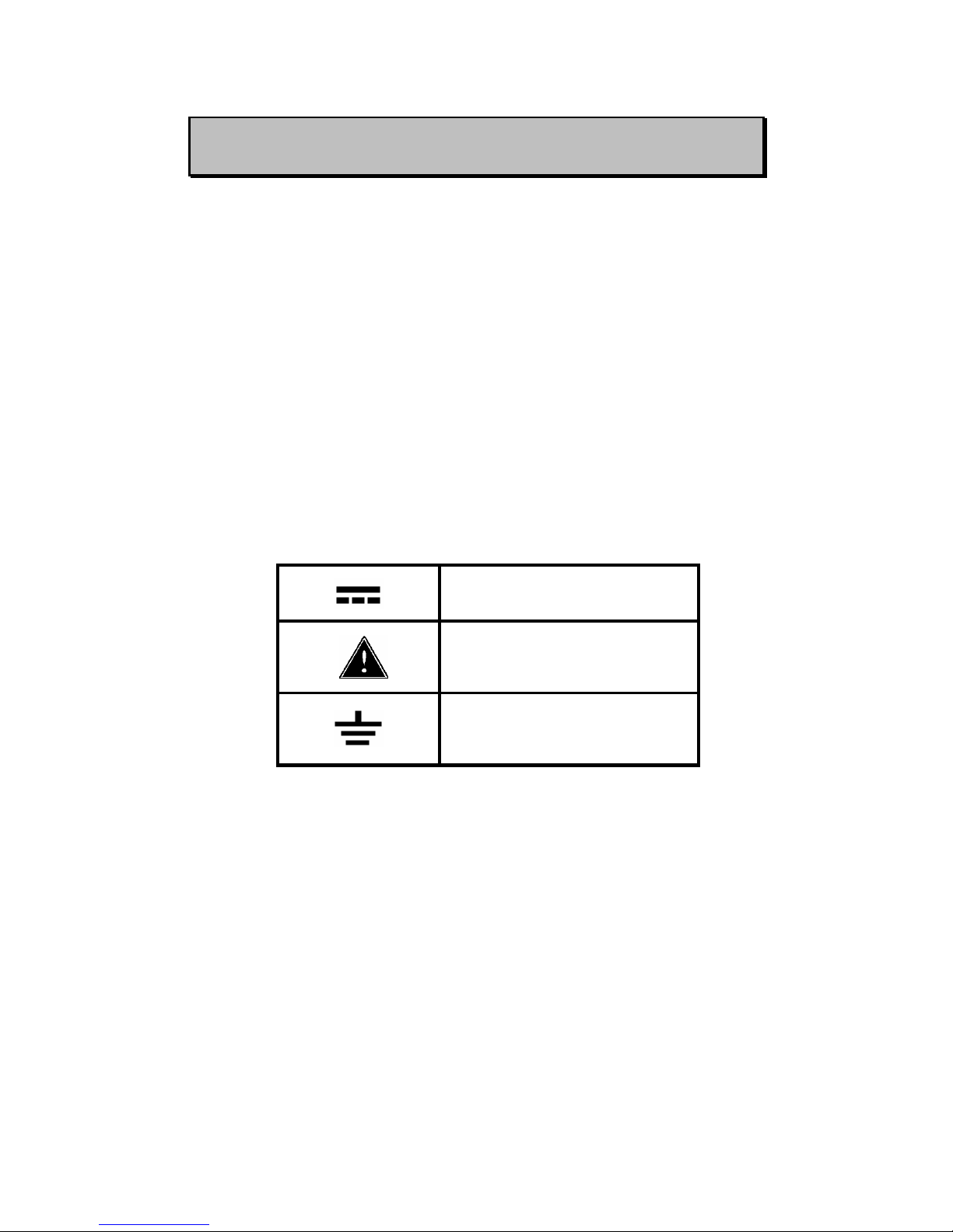
condition. Some common international electrical symbols used in this
manual are shown below Table:
DC - Direct Current
See Explanation In The Manual
Protective conductor
terminated.
Table-1. International Electrical Symbols
Before using the meter, read the following safety information carefully.
In this manual, "WARNING", is reserved for conditions and actions that
pose hazard(s) to the user; "CAUTION", is reserved for conditions and
actions that may damage your meter.
1

SAFETY INFORMATION
To ensure that you use this device safely, follow the safety guidelines
listed below:
1. Before applying power, ensure that power cord and the proper line
voltage indicated for power source being used.
2. This product is grounded through the ground conductor of the power
cord. To avoid electric shock, the ground conductor must be
connected to earth ground. Before making any connections to the
input terminals, ensure that the unit is properly grounded.
3. To avoid personal injury, never operate the instrument without
covers or panels removed.
4. Do not operate this product in wet, damp or explosive atmosphere.
5. This meter is for indoor use, at altitudes up to 2,000m.
6. The warnings and precautions should be read and well understood
before the instrument is used.
7. Use this device only as specified in this manual; otherwise, the
protection provided by the meter may be impaired.
8. When measuring in-circuit components, first de-energize the circuits
before connecting test leads.
9. Discharge the capacitor before testing.
10. The meter is safety-certified in compliance with EN61010
(IEC-1010-1). EMC is certified in compliance with EN61326.
2
INTRODUCTION
This 19,999-count L/C/R meter is a special microprocessor-controlled
meter for measuring functions of inductance, capacitance and
resistance. Extremely simple to operate, the instrument not only takes
absolute parallel mode measurements, but is also capable of series
mode measurement. The meter provides direct and accurate
measurement of inductors, capacitors and resistors with selectable test
frequencies. It utilizes either auto and manual ranging.
Front panel pushbuttons maximize the convenience of function and
feature selection such as data hold; maximum, minimum and average
record mode; relative mode; tolerance sorting mode; frequency and
L/C/R selection.
The test data can be transferred to PC through an optional fully isolated
optical RS232C interface.
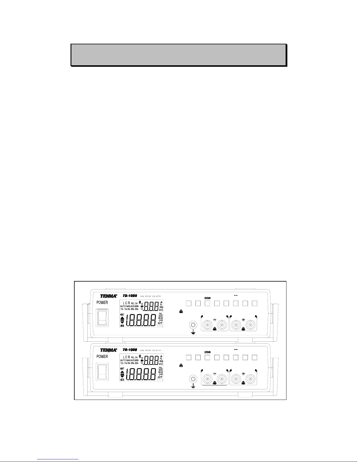
A tilt stand provides position flexibility for viewing and operating the
meter. Its portability and stackable design add ease of use by engineers,
communications technicians, schools and laboratories.
Figure- 1. Stackable Design
RS232
u
u
ALWAYS DISCHARGE THE CAPACITOR BEFORE TESTING
ON
OFF
FORCE
FREQ
FORCE
HOLD
REC
RS232
SENSESENSE
L/C/R
P SAUTO
RANGE TOL
CAL
REL
OFF
RS232
u
u
ON
ALWAYS DISCHARGE THE CAPACITOR BEFORE TESTING
FORCE SENSE SENSE FORCE
TOL
REC
HOLDRS232
AUTO P S
RANGE
FREQ L/C/R
CAL
REL
3
IMPEDANCE THEORY
Impedance
Impedance is an important parameter used to characterize electronic
circuits, components, and the materials used to make components.
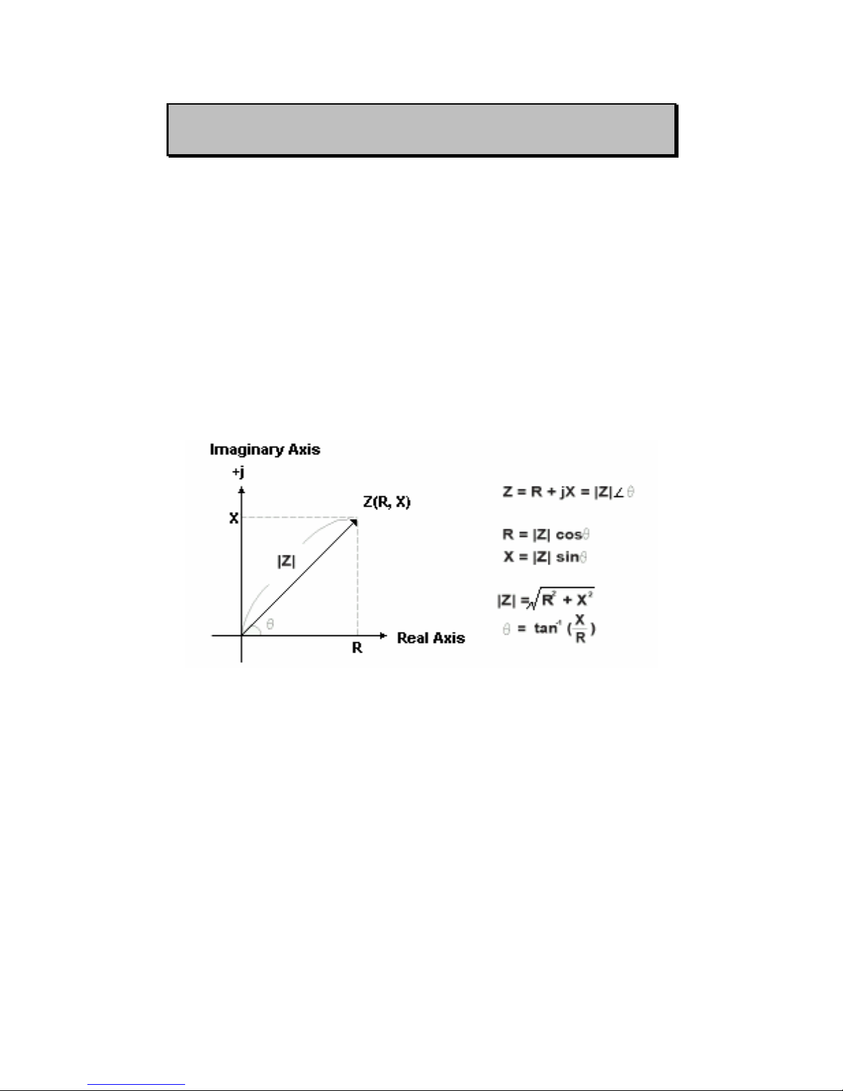
Impedance (Z) is generally defined as the total opposition a device or
circuit offers to the flow of an alternating current (AC) at a given
frequency, and is represented as a complex quantity, which is
graphically shown on a vector plane. An impedance vector consists of a
real part (resistance, R) and an imaginary part (reactance, X) as shown
in Figure-2.
Figure- 2. Impedance
Impedance can be expressed using the rectangular-coordinate form R+
jX or in the polar form as a magnitude and phase angle: |Z| ∠θ.
Figure-3 also shows the mathematical relationship between R, X, |Z|
and θ.
The unit of impedance is the ohm (Ω). Impedance is a commonly used
parameter and is especially useful for representing a series connection
of resistance and reactance, because it can be expressed simply as a
sum, R and X.
4
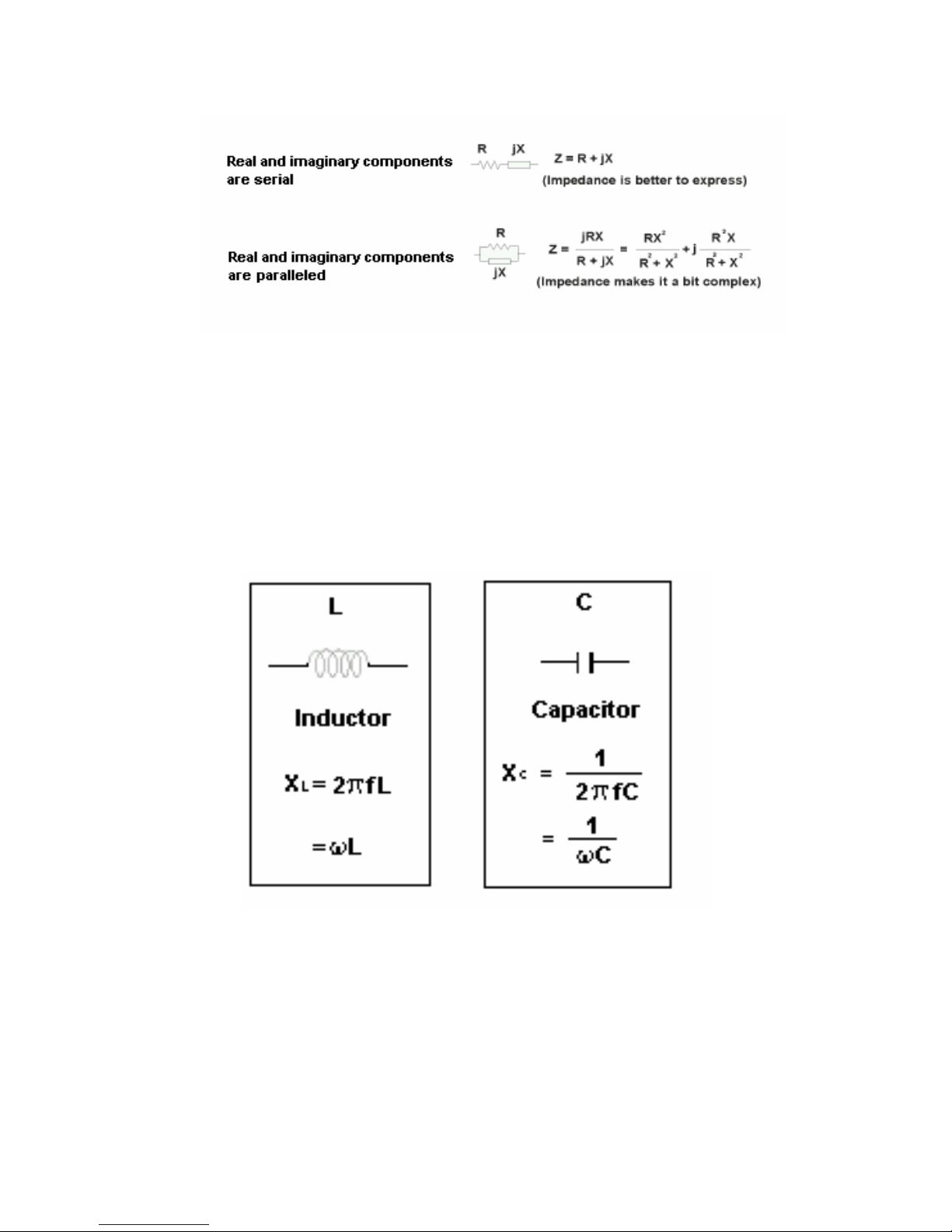
Figure- 3. Expression of series and parallel combination
Reactance takes two forms - inductive (XL) and capacitive (Xc). By
definition, X
L=2πfL and Xc=1/(2πfC), where f is the frequency of interest,
L is inductance, and C is capacitance. 2πf can be substituted for by the
angular frequency (ω:omega) to represent XL=ωL and Xc=1/(ωC). Refer
to Figure-4.
Figure- 4. Reactance in two forms - XL and Xc
Figure-5 shows a typical representation for a resistance and a
reactance connected in series. The quality factor (Q) serves as a
measure of a reactance’s purity (how close it is to being a pure
reactance, no resistance), and is defined as the ratio of the energy
stored in a component to the energy dissipated by the component. Q is
5
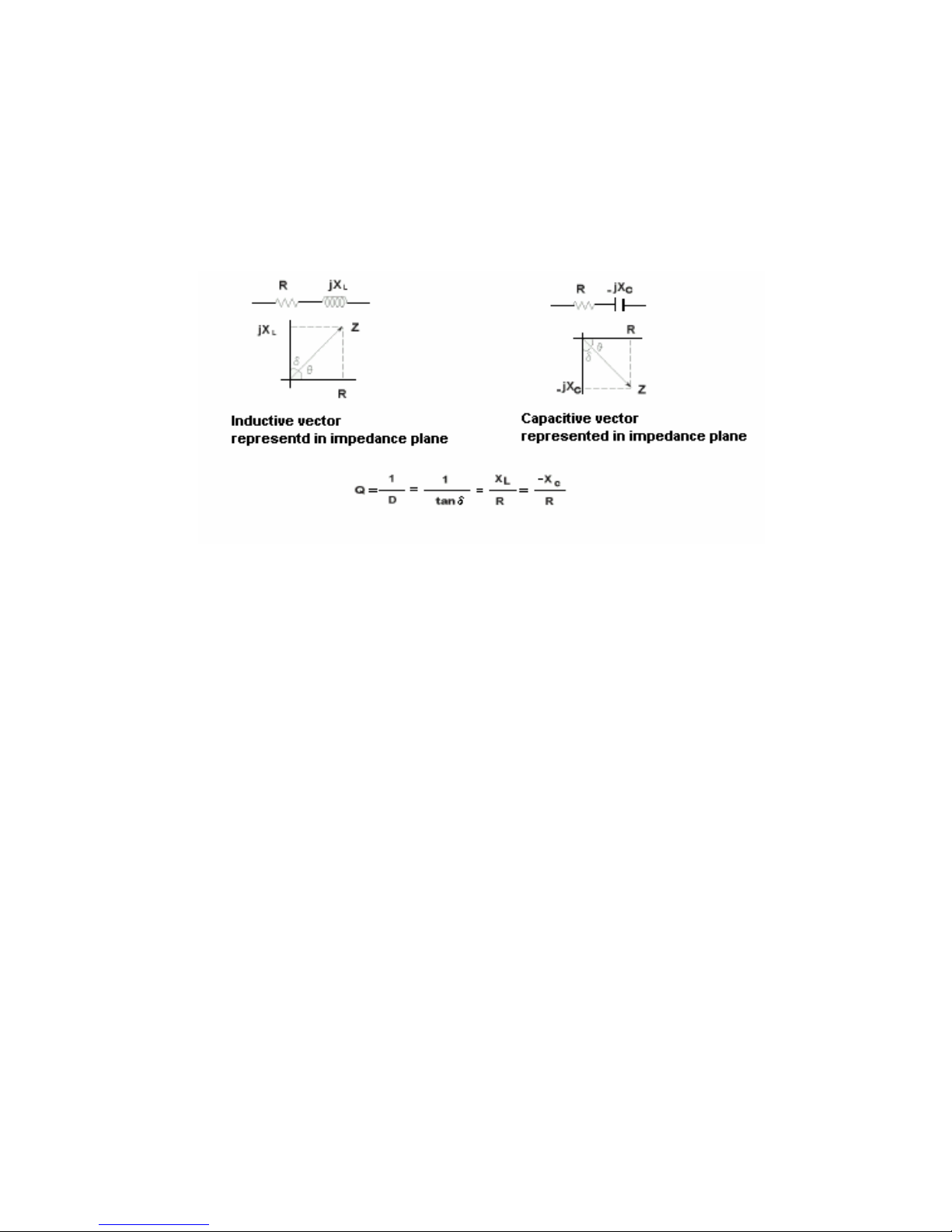
a dimensionless unit and is expressed as Q=X/R. From Figure-5, you
can see that Q is the tangent of the angle θ. Q is commonly applied to
inductors; for capacitors the term more often used to express purity is
dissipation factor (D). This D quantity is simply the reciprocal of Q. It is
the tangent of the complementary angle of θ.
Figure- 5. Relationships between resistance and reactance
6

Measuring impedance
To find the impedance, we should measure two values at least because
impedance is a complex quantity. Many modern impedance instruments
measure the real and the imaginary parts of an impedance vector and
then convert them into the desired parameters such as |Z|, θ
, L, C, R, X, It is only necessary to connect the unknown component,
circuit, or material to the instrument. However, sometimes the
instrument will display an unexpected result (too high or too low). One
possible cause of this problem is incorrect measurement technique, or
the natural behavior of the unknown device. We will focus on the
traditional passive components and discuss their natural behavior in the
real world as compared to their idealistic behavior.
Parasitic
There are no pure L, C or R. All circuit components are neither pure
resistive nor pure reactive, they are a combination of these impedance
elements. The result all devices have parasites - unwanted inductance
in resistors, unwanted resistance in capacitors, unwanted capacitance
in inductors, etc. Of course, different materials and manufacturing
technologies produce varying amounts of parasites, affecting both a
component’s usefulness and the accuracy with which you can
determine its resistance, capacitance, or inductance. A real-world
component contains many parasites. With the combination of a
component’s primary element and parasites, a component will be like a
complex circuit.
7
Real, effective, and indicated values
A thorough understanding of real, effective, and indicated values of a
component, as well as their significance to component measurements,
is essential before you proceed with making practical measurements.
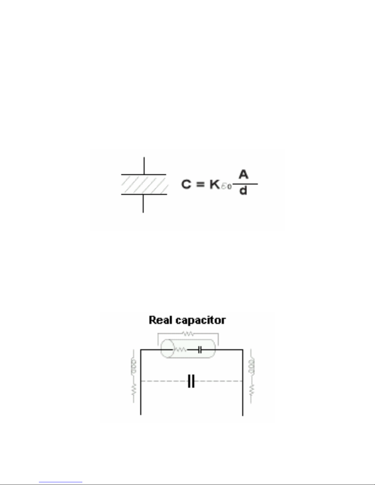
A real value is the value of a circuit component (resistor, inductor or
capacitor) that excludes the defects of its parasites. In many cases, the
real value can be defined by a mathematical relationship involving the
component’s physical composition. In fact, real values are only of
academic interest (Figure-6).
Figure- 6. Real capacitor value
The effective value takes into consideration the effects of a
component’s parasites. The effective value is the algebraic sum of the
circuit component’s real and reactive vectors; thus, it is frequency
dependent (Figure-7).
Figure- 7. Effective value
8
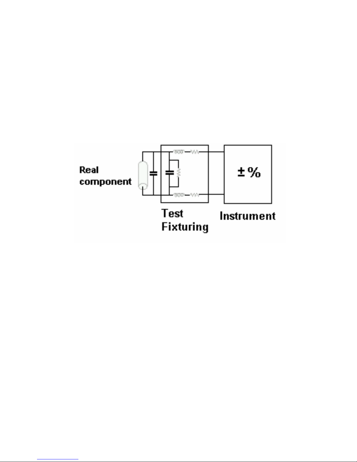
The indicated value is the value obtained with and displayed by the
measuring instrument; it reflects the instrument’s inherent losses and
inaccuracies. Indicated values always contain errors when compared to
true or effective values. They also vary intrinsically from one
measurement to another; their differences depend on a multitude of
considerations. Comparing how closely an indicated value agrees with
the effective value under a defined set of measurement conditions lets
you judge the measurement’s quality (Figure-8).
Figure- 8. Indicated value
The effective value is what we want to know, and the goal of
measurement is to have the indicated value to be as close as possible
to the effective value.
9
Component dependency factors
The measured impedance value of a component depends on several
measurement conditions, such as frequency, test signal level, and so on.
Effects of these component dependency factors are different for
different types of materials used in the component, and by the
manufacturing process used. The following are typical dependency
factors that affect measurement results.
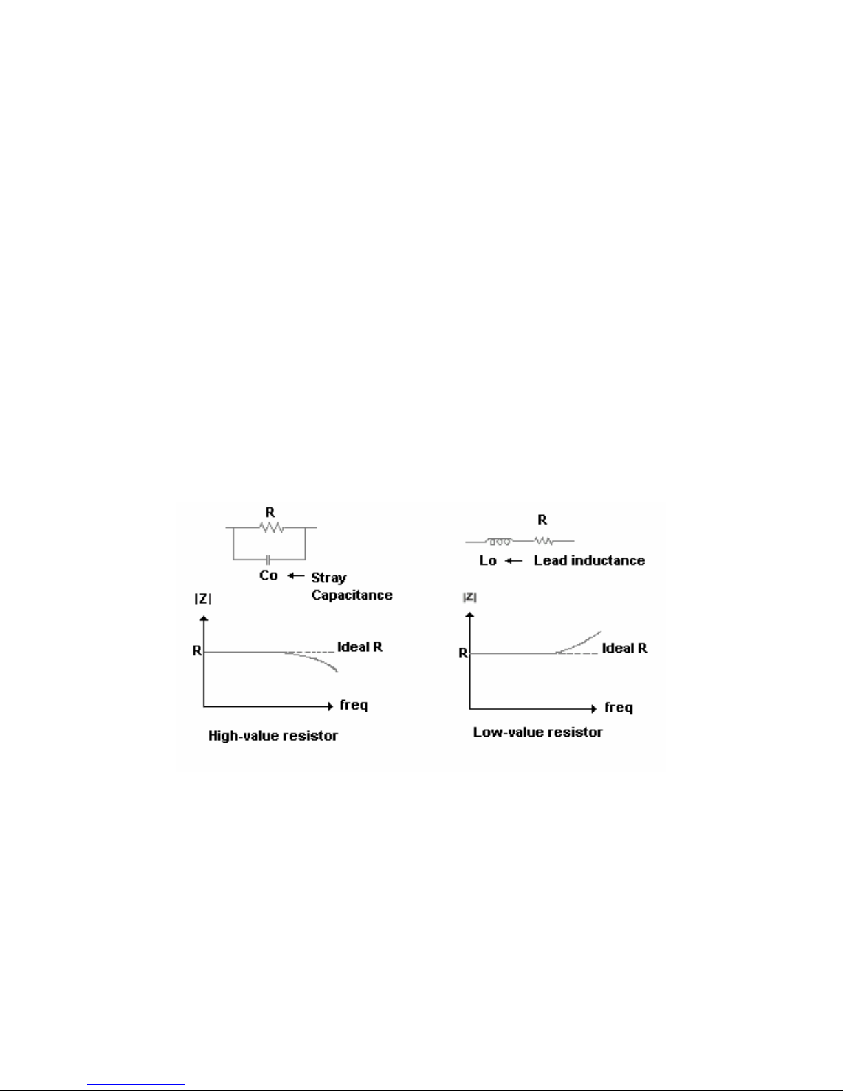
1. Frequency
Frequency dependency is common to all real components because of
the existence of parasites. Not all parasites affect the measurement, but
some prominent parasites determine the component’s frequency
characteristics. The prominent parasites will be different when the
impedance value of the primary element isn’t the same. The typical
frequency response for real resistors, capacitors and inductors is shown
as Figure-9, 10 and 11, respectively.
Figure- 9. Resistor frequency response
10
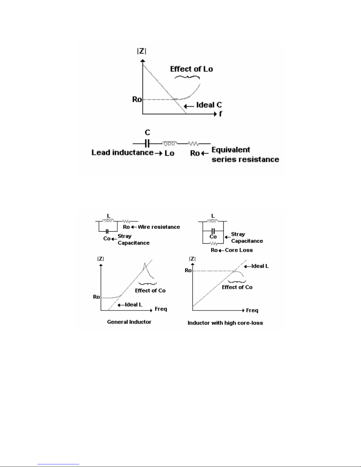
Figure- 10. Capacitor frequency response
Figure- 11. Indicator frequency response
11
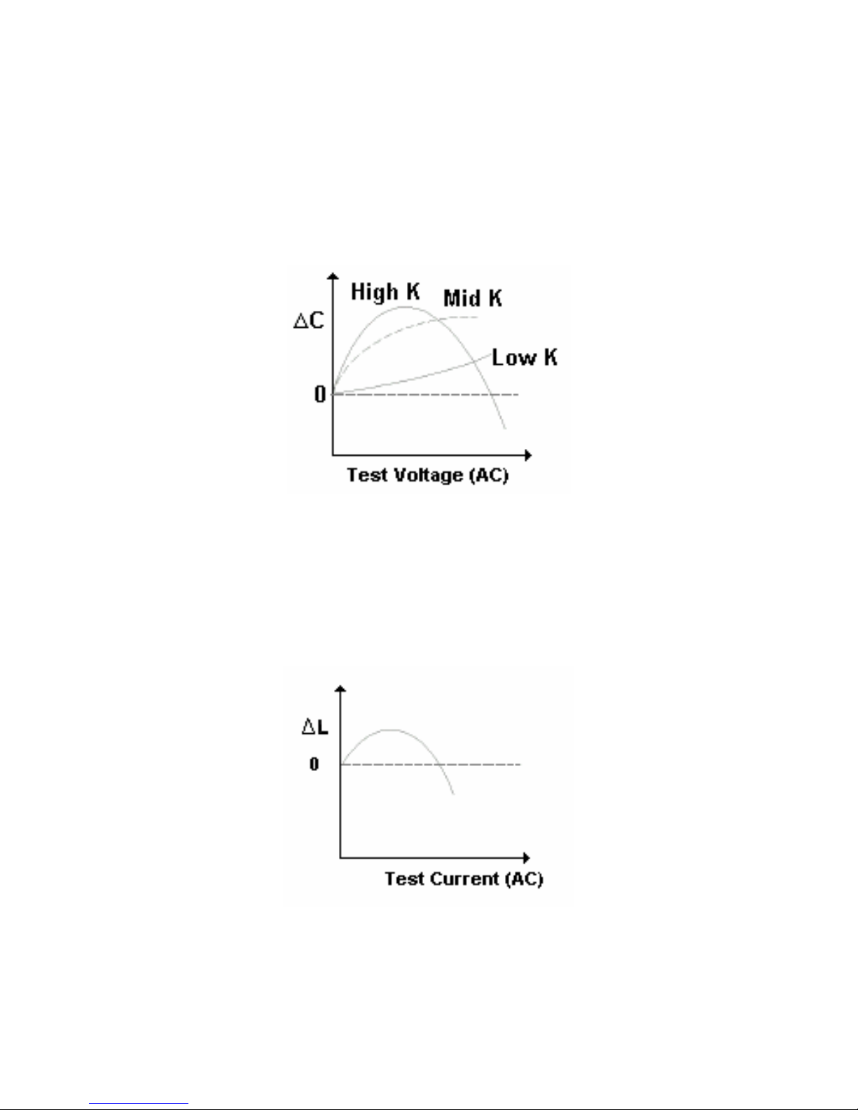
2. Test signal level
The test signal (AC) applied may affect the measuring result for some
components. For example, ceramic capacitors are test signal voltage
dependent as shown in Figure -12. This dependency varies depending
on the dielectric constant (K) of the material used to make the ceramic
capacitor.
Figure- 12. AC voltage dependency for Ceramic capacitor
Cored-inductors are test signal current dependent due to the
electromagnetic hysteresis of the core material. Typical AC current
characteristics are shown in Figure-13.
Figure- 13. AC current dependency for Cored-inductor
12
 Loading...