

Tenma 72-10175 User Manual
Tenma 72-10175
USER’S
MANUAL
Tenma Test Equipment 405 S.Pioneer Blvd.Springboro,OH 45066
www.tenma.com
TENMA 72-10175
X
DIGITAL OSCILLOSCOPE
USER’S MANUAL
72-10175

Appendix B.............................................................106
CHAPTER 3:Functions
Self Calibration........................................................21
Y
Content
General Safety Summary ……..………………………….…..3
CHAPTER 1: Getting Started…...…………………………... 4
System Requirement..……………………………
…
....5
Install Software........………………………………...…6
Install Driver............………………………………
....
.11
General Features....………………………………….16
General Check............…………………………
…..
...17
Probe Compensation.................…………………....17
Functional Check.................………………..……
...
.19
Accessaries.............................................................22
CHAPTER 2: Operating Basics……………………………..23
The User’s Inerface……………………………
…….
..24
The Vertical System…...........…………………
…….
.30
The Horizontal System…………………….....…
…..
.32
The Trigger System............................……………...33
Input Connectiors..………………………
…………
...35
..………………
…...36
Set Ocsilloscope.....................................................37
Set Vertical System.................................................38
Set Horizontal System............................................47
Set Trigger System.................................................55
Save/Load..............................................................55
Utility Function........................................................57
Measure Signal.......................................................65
The Display System................................................73
Zoom In/Out and Drag waveforms..........................78
Interpolation............................................................80
Acquisition..............................................................83
Print........................................................................84
CHAPTER 4: Application Example......………………….....86
Simple Measurement..............................................87
Pass/Fail Test..........................................................89
Capturing a Single Shot Signal...............................93
The Application of The X-Y.......................................94
Taking Cursor Measurements...................................97
CHAPTER 5: Appendix..............………………
……
...101
Appendix A.............................................................102
..………………

tion before making connections to the product.
Use Proper Probe.
Observe All Terminal Rating.
To avoid shock hazard, use a properly rated probe for your meas-
and markings on the product. Consult the product manual for further ratings informa-
TENMA 72-10175
Z
DIGITAL OSCILLOSCOPE
General Safety Summary
Review the following safety precautions carefully before operate the device to avoid any
personal injuries or damages to the device and any products connected to it.
To avoid potential hazards use the device as specied by this user’s guide only.
To Avoid Fire or Personal Injury
Use Proper Power Cord. Use only the power cord specied for this product and
certied for the country of use.
Connect and Disconnect Properly. Do not connect or disconnect probes or test
leads while they are connected to a voltage source.
Connect and Disconnect Properly. Connect the probe output to the measurement
device before connecting the probe to the circuit under test. Disconnect the probe
input and the probe reference lead from the circuit under test before disconnecting
the probe from the measurement device.
To avoid re or shock hazard, observe all ratings
urement.
Avoid Circuit or Wire Exposure. Do not touch exposed connections and compo
nents when power is on.
Do Not Operate With Suspected Failures. If suspected damage occurs with the
device, have it inspected by qualied service personnel before further operations.
Provide Proper Ventilation. Refer to the installation instructions for proper ventilation
of the device.
Do not operate in Wet/Damp Conditions.
Do not operate in an Explosive Atmosphere.
Keep Product Surfaces Clean and Dry.
-
-
-

tions involving analog circuits test and troubleshooting, as well as education and training.
power! The 72-10175 is ideal for production test,research,design and any other applica-
The 72-10175 is small, lightweight, portable oscilloscope which does not require external
[
Chapter 1 Getting Start
In addition to the list of general features on the next page, this chapter describes how to
do the following tasks:
System Requirements
Install your product
General Features
General Check
Perform a probe check and compensate probes
Match your probe attenuation factor
Use the self calibration routine
Accessories

80GB Disk Space
1GB Memory
256MB
1.00GHz processor
TENMA 72-10175
\
DIGITAL OSCILLOSCOPE
System Requirement
To run the oscilloscope software, the needs of computer conguration are as follows:
Minimum System Requirements
Operating System
Window NT/2000/XP/VISTA/Win7
Processor
Memory
Disk Space
500M disk free space
Screen resolution
800 x 600
Recommended Conguration
Operating System
Windows XP SP3 System
Processor
2.4G Processor
Memory
Disk Space
Screen resolution
1024 x 768 or 1280 x 1024 resolution
DPI Setting
Normal Size (96DPI)
]
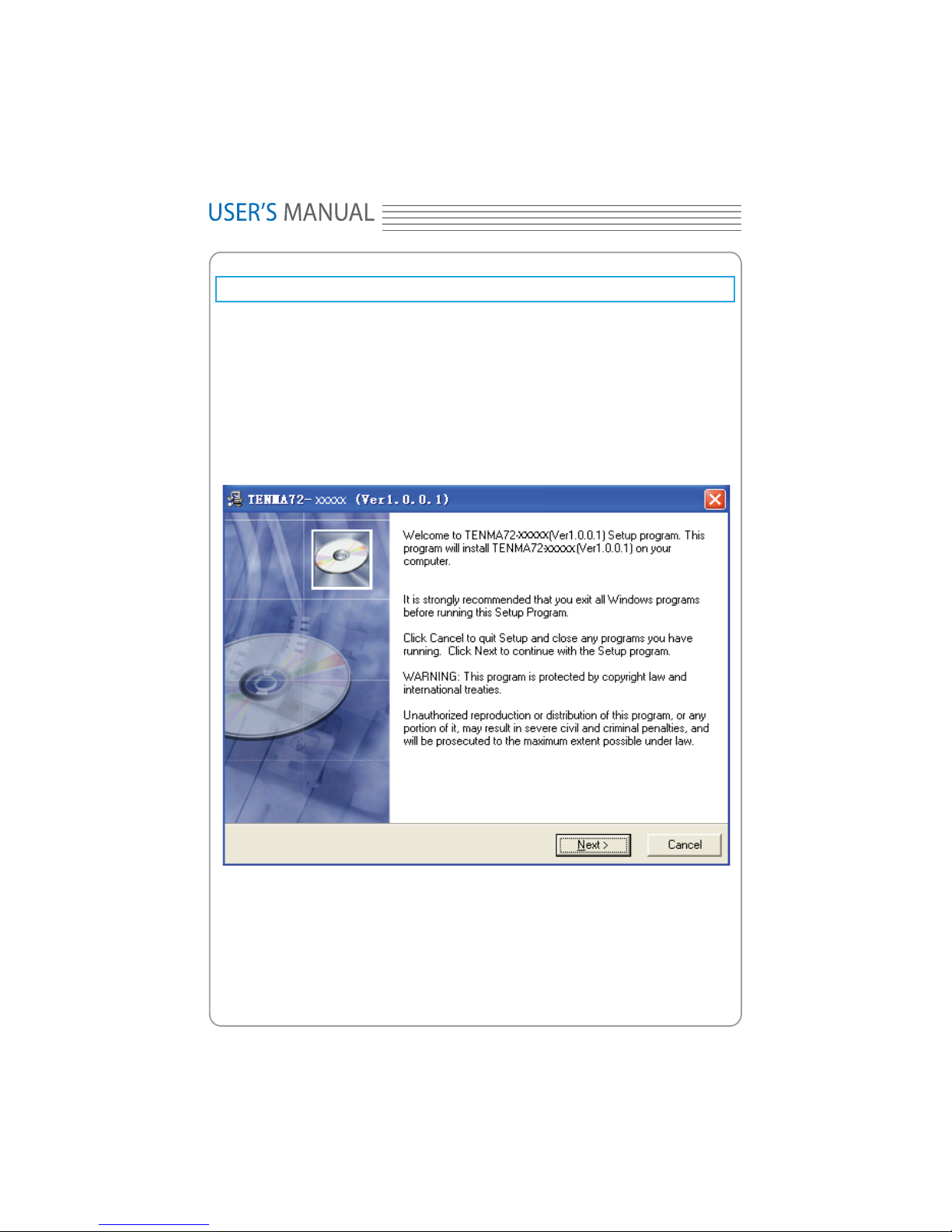
Install Software
Caution: You must install the software before using the oscilloscope.
1. While in Windows, insert the installation CD into the CD-ROM drive.
2. The installation should start up automatically. Otherwise in Windows Explorer, switch
to the CD-ROM drive and run Setup.exe.
3. The software Installation is started. Click 'Next' to continue.
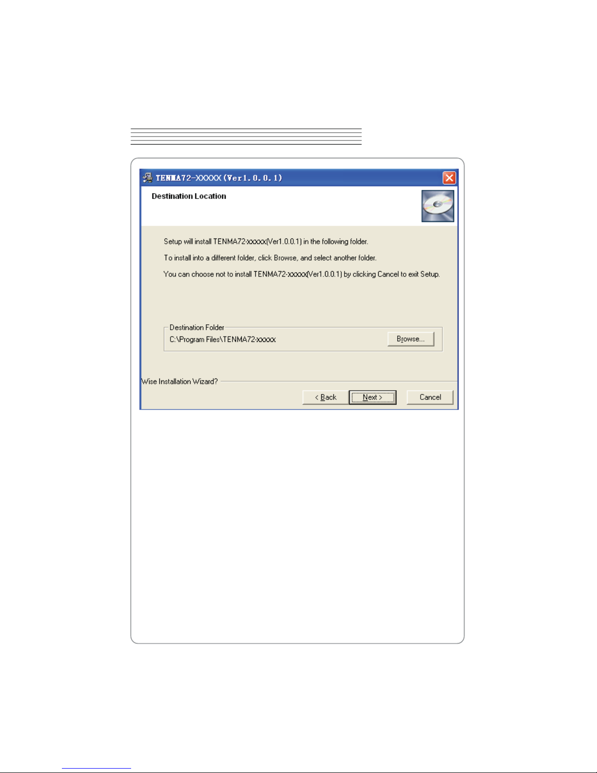
4. Choose a destination directory. Click 'Next' to continue.
TENMA 72-10175
^
DIGITAL OSCILLOSCOPE
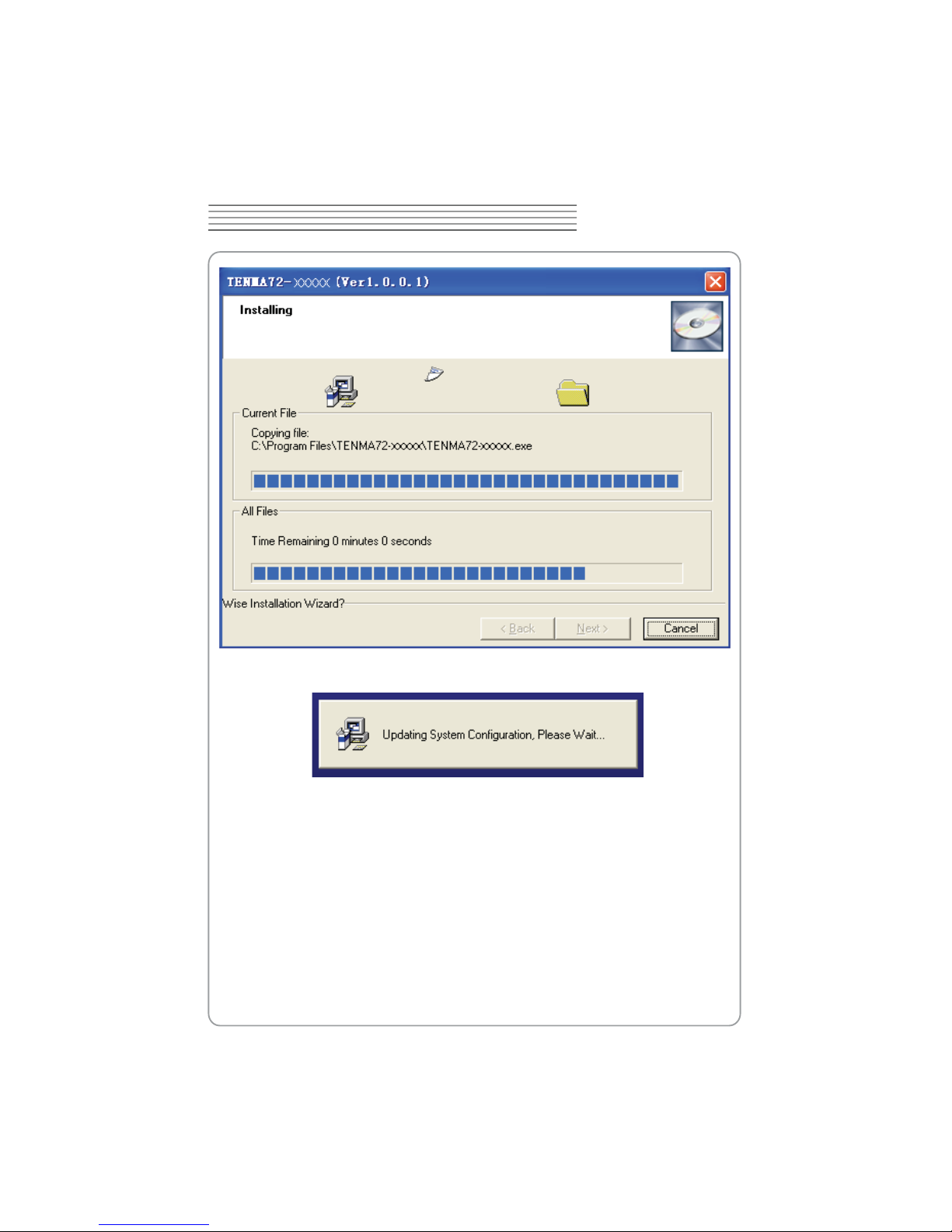
5. Check the setup information. Click Next to start copying of les.

_
6. This Status dialog is displayed during copying of les.
TENMA 72-10175
`
DIGITAL OSCILLOSCOPE
7. Updating Your System Conguration.
XW
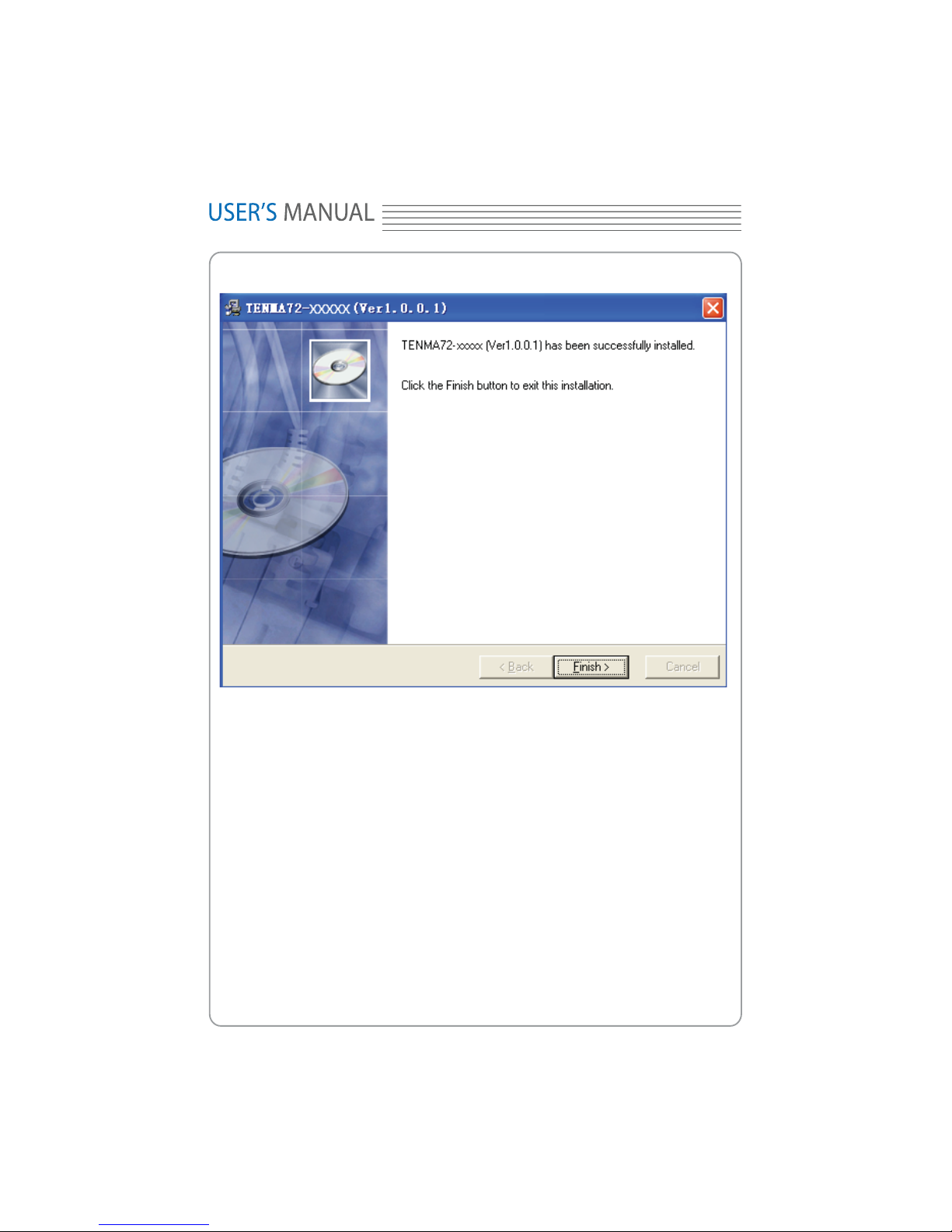
8. The installation is complete.
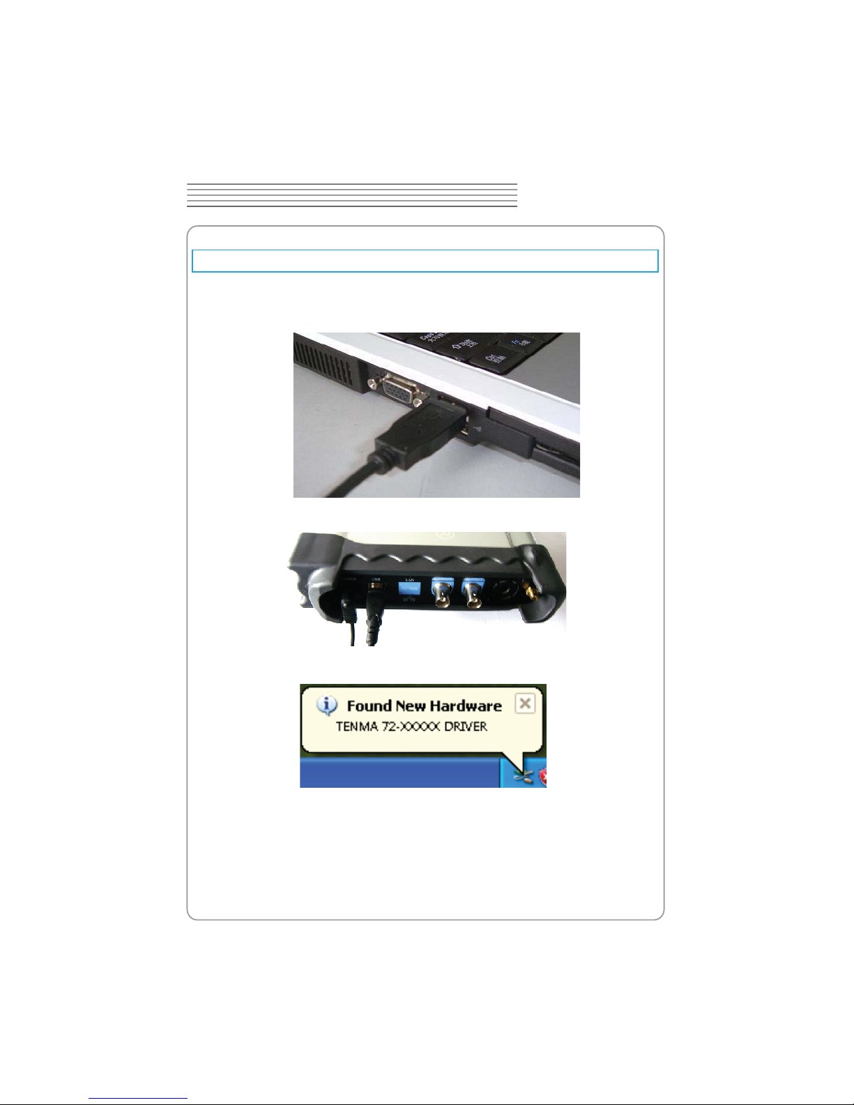
2. Connect the B-Type Plug of USB cable to USB’S USB port.
TENMA 72-10175
XX
DIGITAL OSCILLOSCOPE
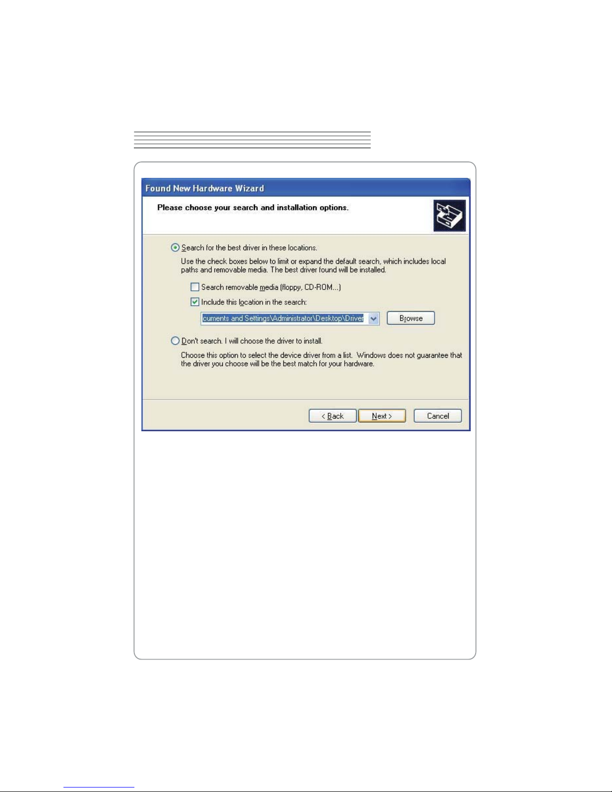
Install Driver
1. Connect the A-Type Plug of USB cable to your PC’S USB port.
3. New hardware is found.
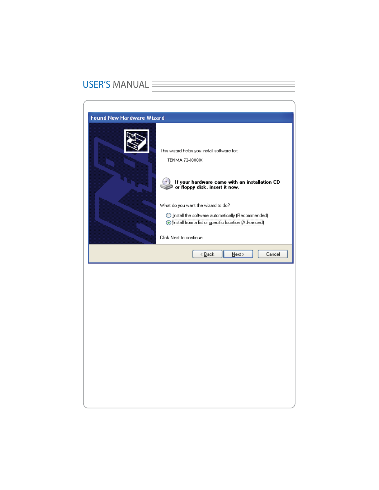
4. New hardware search wizard starts.
XY
5. Select the specic location.
TENMA 72-10175
XZ
DIGITAL OSCILLOSCOPE
6. New hardware search wizard starts to search the driver.
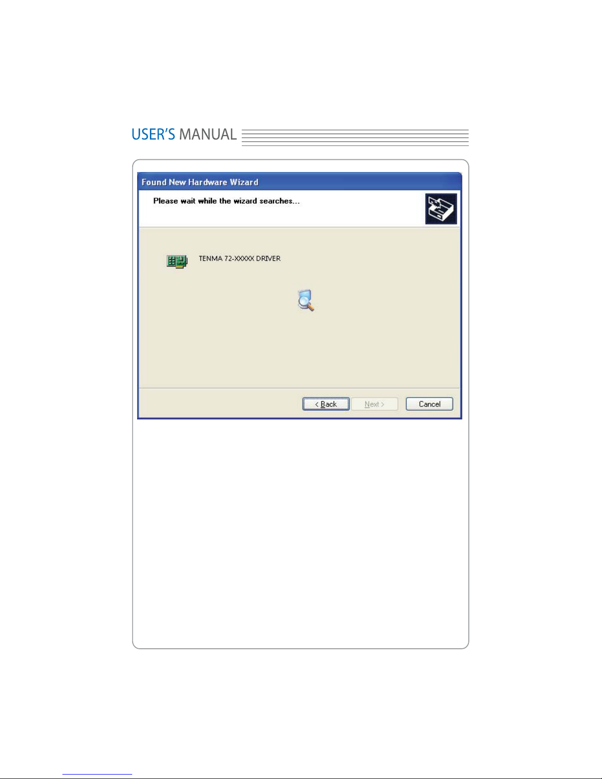
7. New hardware wizard installs “USB DRIVER ”.
X[
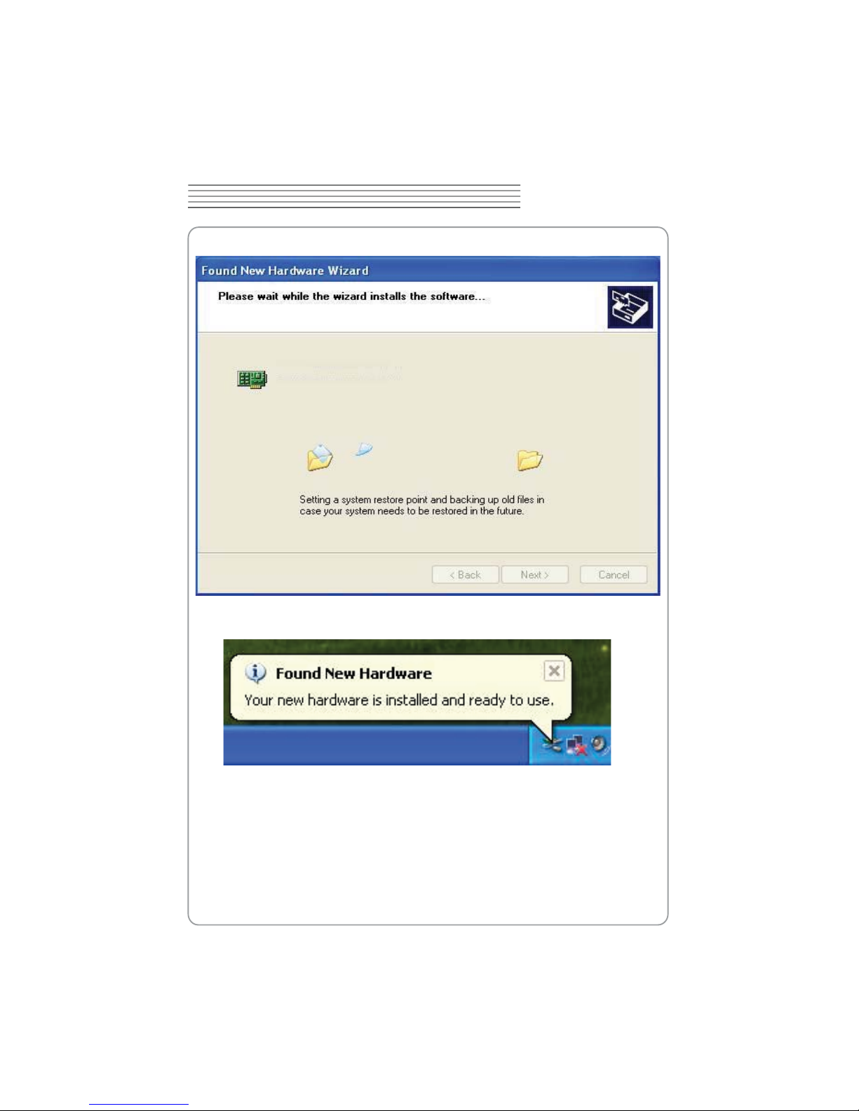
8. The wizard has nished installing for “USB DRIVER”.
TENMA 72-10175
X\
DIGITAL OSCILLOSCOPE
Product features:
Automatic setup for ease of use (AUTOSET);
Four channel,Bandwidth:
X]
General Features
60MHz
Maximum real-time sample rate:
200MSa/s
Memory depth:
10K-16M points
Pass/Fail;
Built-in Fast Fourier Transform function(FFT);
20 Automatic measurements;
Automatic cursor tracking measurements;
Waveform storage, record and replay dynamic waveforms;
User selectable fast offset calibration;
Add, Subtract and Multiply Mathematic Functions;
Selectable 20 MHz bandwidth limit;
External trigger;
Waveform average;
Adjustable waveform intensity, more effective waveform view;
User interface in several user-selectable languages;

properly or fails performance tests, please notify the distributor.
contents are incomplete or damaged,please notify the distributor.
Please check the instrument for the following steps before use.
TENMA 72-10175
X^
DIGITAL OSCILLOSCOPE
General Check
Check the shipping container for damage:
Keep the damaged shipping container or cushioning material until the contents of the
shipment have been checked for completeness and the instrument has been checked
mechanically and electrically.
Check the accessories:
Accessories supplied with the instrument are listed in "Accessories" in this guide. If the
Check the instrument:
In case there is any mechanical damage or defect, or the instrument does not operate
.
Probe Compensation
Perform this function to match the characteristics of the probe and the channel input.
This should be performed whenever attaching a probe to any input channel at the rst
time.
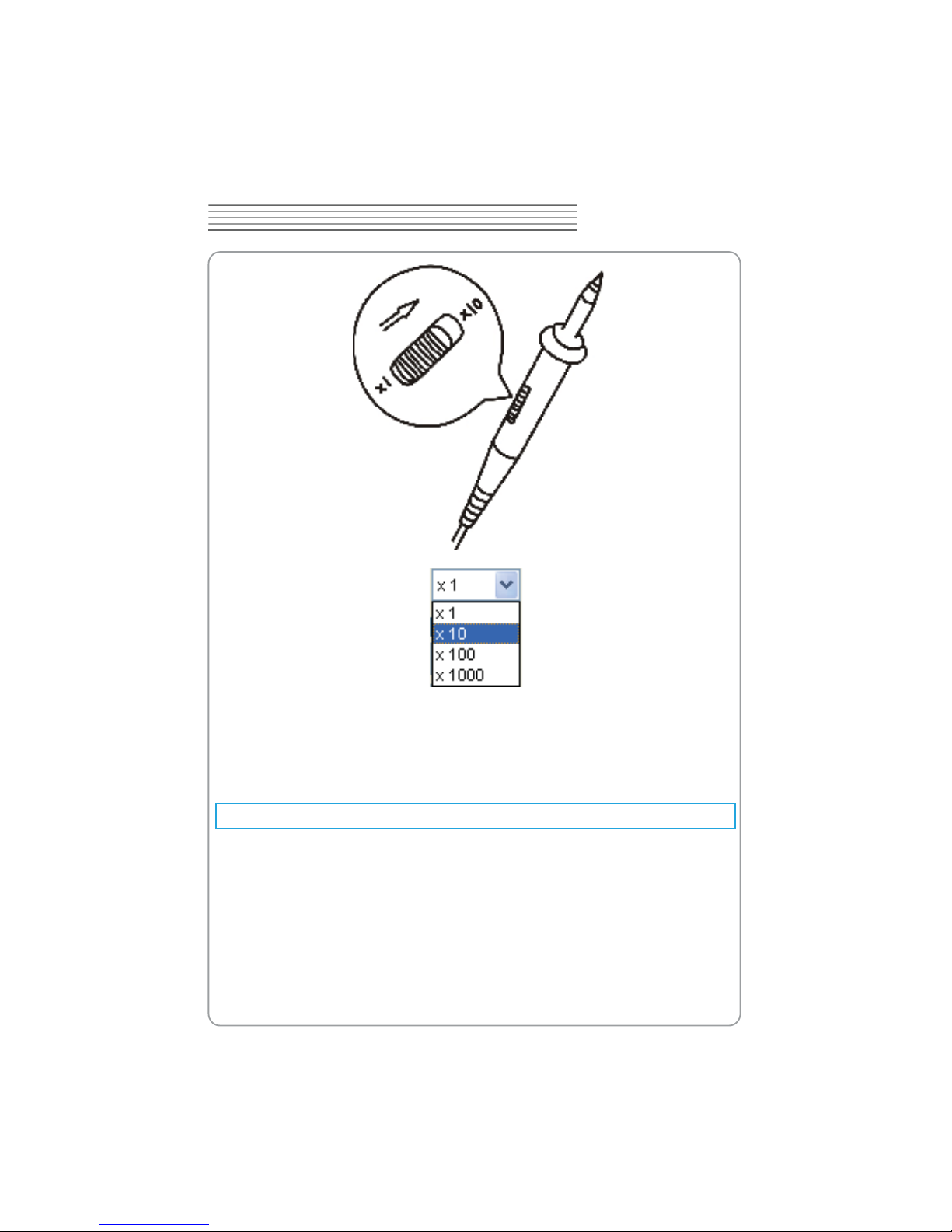
From the “Probe” menu, select attenuation to 1:10. Set the switch to “X10” on the
probe and connect it to CH1 of the oscilloscope. When using the probe hook-tip, insert
the tip onto the probe rmly to ensure a proper connection.
Attach the probe tip to the Probe Compensator and the reference lead to the ground
connector, select CH1, and then press the “AUTOSET“ button into the menu or the
toolbar.
Check the shape of the displayed waveform.
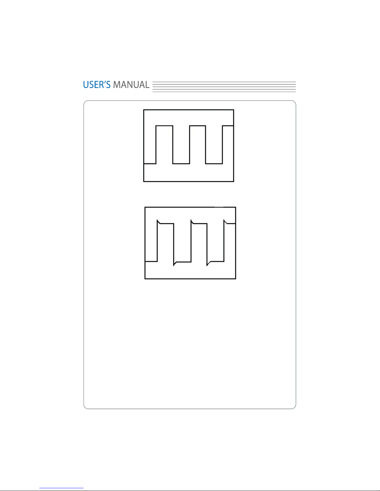
X_
Correctly Compensated
Over compensated
TENMA 72-10175
X`
DIGITAL OSCILLOSCOPE
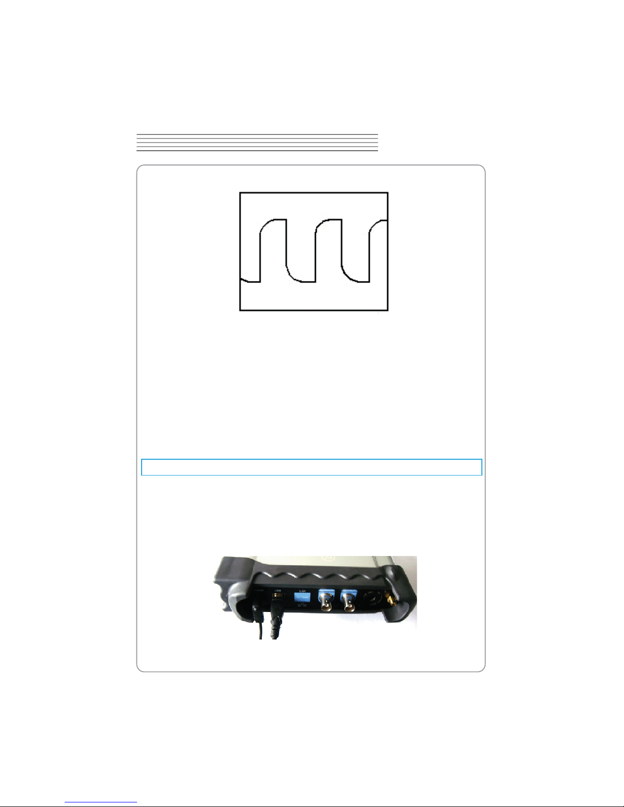
Under Compensated
If necessary, use a non-metallic tool to adjust the trimmer capacitor of the probe for
the attest square wave being displayed on the oscilloscope.
Repeat if necessary.
WARNNING: To avoid electric shock while using the probe, be sure the perfection of the
insulated cable, and do not touch the metallic portions of the probe head while it is connected with a voltage source.
Function Check
Perform this functional check to verify that your oscilloscope is operating correctly.
Connect the oscilloscope
You should connect the A-Type Plug of USB cable to your PC USB port and connect
the B-Type Plug of USB cable to oscilloscope USB port.
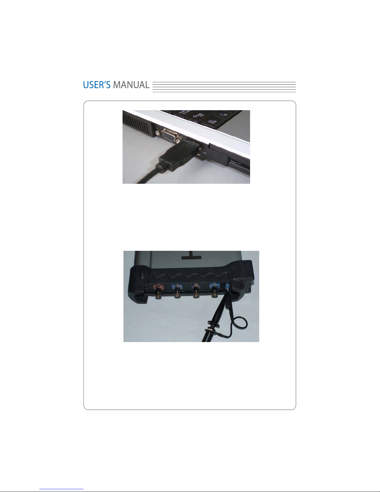
loscope with CH1. Allign the slot in the probe connector at the end on BNC of CH1
1. Set the attenuation switch on the probe as 10X and connect the probe on the oscil-
YW
Input a signal to a channel of the oscilloscope
The oscilloscope is equipped with four channels plus external trigger.
Please input signal in the following steps:
and insert, then, turn right to lock the probe. Finally, attach the tip of probe and ground
nip to the Connector of Probe compensator.
2. Set the CH1 probe attenuation of the oscilloscope to X10. (The default is X1).
TENMA 72-10175
YX
DIGITAL OSCILLOSCOPE
3. Attach the tip of probe and ground nip to the Connector of Probe compensator. Click
the button. A square wave will be displayed within a several seconds. (Approximately
1 kHz, 2V, peak- to- peak).
4. Inspect CH2 ,CH3 and CH4 with the same method. Repeat steps 2 and 3.
Self Calibration
The self calibration routine lets you optimize the oscilloscope signal path for maximum
measurement accuracy. You can run the routine at any time but you should always run
the routine if the ambient temperature changes by 5v or more. For accurate calibration, power on the oscilloscope and wait twenty minutes to ensure it is warmed up. To
compensate the signal path, disconnect any probes or cables from the input connectors.
Then, access the “Utility -> Calibration” option and follow the directions on the screen.
The self calibration routine takes about several minutes.
YY
Accessories
All the accessories listed below are standard accessories for the oscilloscope:
Probe×2 (1.5m), 1:1, (10:1) Passive Probes
A User’s Guide
An USB Cable
A PC software of the oscilloscope

TENMA 72-10175
YZ
DIGITAL OSCILLOSCOPE
Chapter 2 Operating Basics
The User’s Interface
The Menu System
The Vertical System
The Horizontal System
The Trigger System
Input Connectors
Displays the edge trigger slope, source and level.
Displays the trigger information
Y[
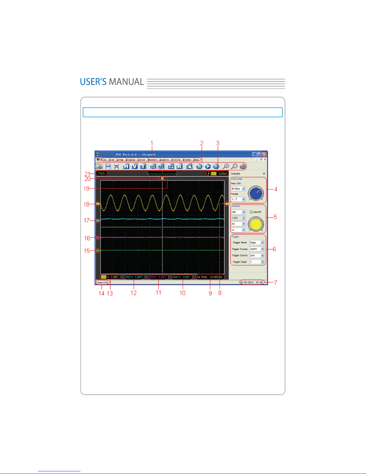
The User’s Interface
Click the software icon on the desk after you nished the software setting and equipment
connecting. Then a user interface will be showed as follows:
In addition to displaying waveforms, the display area is lled with many details about the
waveform and the oscilloscope control settings.
1. The Main Menu
All settings can be found in the main menu.
2. The Toolbar
3.
4. The Horizontal Panel

The same above.
The same above.
The same above.
Displays the software status.
Displays the CH2 information
Displays the CH3 information
Displays the main time base setting.
Marker shows Edge trigger level.
Displays the system time.
13.
Displays the CH1 information
Displays the CH4 information
TENMA 72-10175
Y\
DIGITAL OSCILLOSCOPE
The user can change Time/Div, format in the panel.
5. The Vertical Panel
The user can turn on/off the CH1/CH2/CH3/CH4. Also the user can change the CH1/
CH2/CH3/CH4 volt/div, coupling and probe attenuation.
6. The Trigger Panel
In this panel, the user can change the trigger mode, sweep, source and slope.
7.
8.
9.
10.
Readouts show the coupling of the channels.
Readouts show the vertical scale factors of the channels.
A “B” icon indicates that the channel is bandwidth limited.
11.
Readouts show the coupling of the channels.
Readouts show the vertical scale factors of the channels.
A “B” icon indicates that the channel is bandwidth limited.
12.
Readouts show the coupling of the channels.
Readouts show the vertical scale factors of the channels.
A “B” icon indicates that the channel is bandwidth limited.
Readouts show the coupling of the channels.
Readouts show the vertical scale factors of the channels.
A “B” icon indicates that the channel is bandwidth limited.
14.
15. The markers show the reference points of the displayed waveforms. If there is
no marker, the channel is not displayed.
16.
17.
18.

Y]
19. A window that shows the display waveform in buffer position.
20. Marker shows horizontal trigger position.
21. Trigger status indicates the following:
AUTO: The oscilloscope is in auto mode and is acquiring waveforms in the absence
of triggers.
Trig’D: The oscilloscope has seen a trigger and is acquiring the post trigger data.
WAIT: All pretrigger data has been acquired and the oscilloscope is ready to accept
a trigger.
STOP: The oscilloscope has stopped acquiring waveform data.
RUN: The oscilloscope is running.
PLAY: The oscilloscope is displaying the record waveforms.
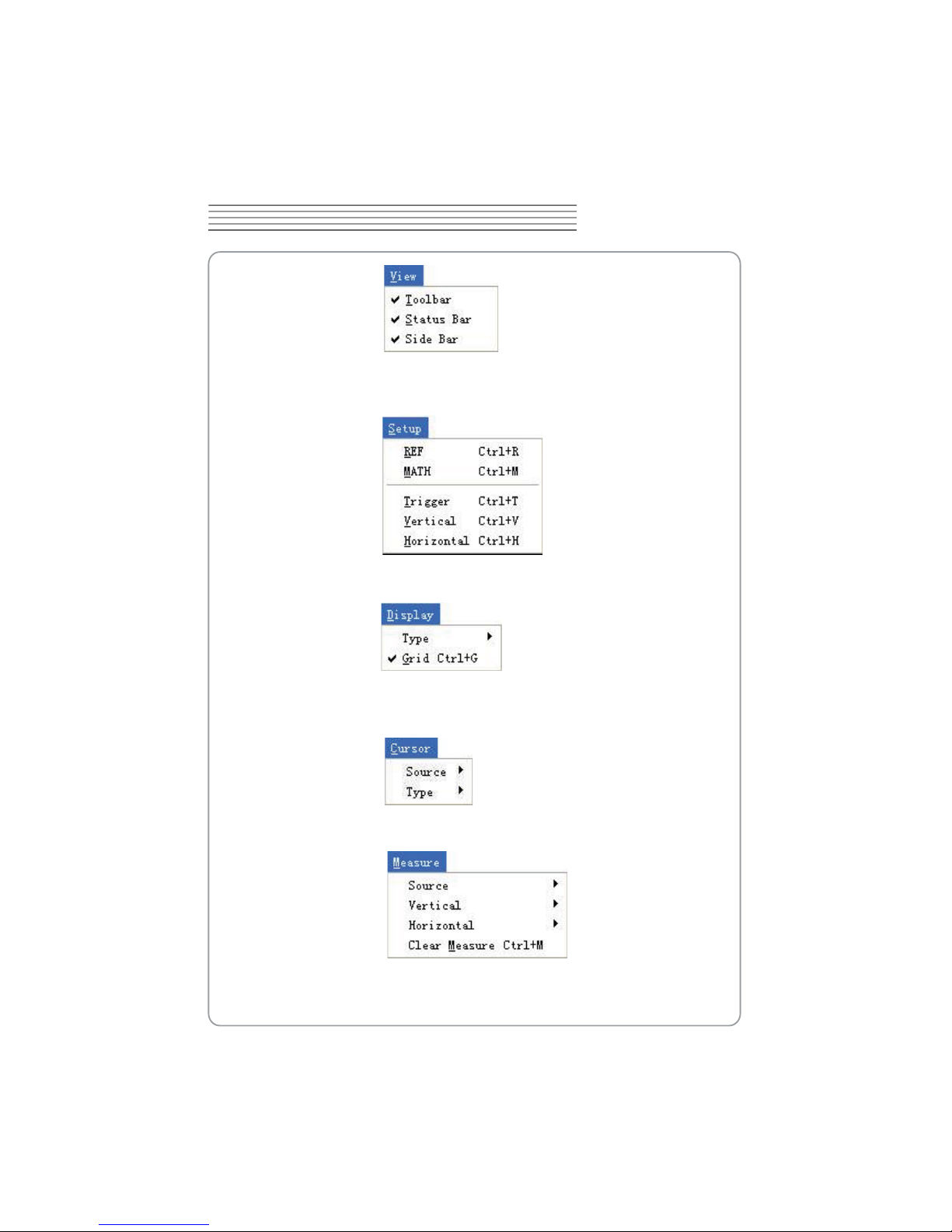
The Menu System
The Main Menu
1. File: Load or Save data, setup
2. View: Change the user interface
TENMA 72-10175
Y^
DIGITAL OSCILLOSCOPE
3. Setup: Setup setting
4. Display: Change wave display type
5. Cursor: Set Cursor measure type
6. Measure: Set measurement parameters
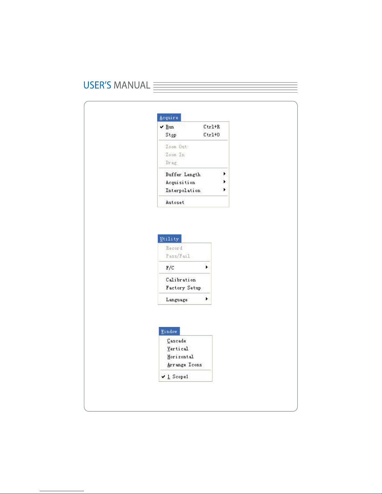
7.Acquire: Run ,Stop or other operation setting
: Access help le
Y_
8. Utility: Utility setting
9. Window: Window setting
11. Help
TENMA 72-10175
Y`
DIGITAL OSCILLOSCOPE
 Loading...