

Page 1
Operating Manual
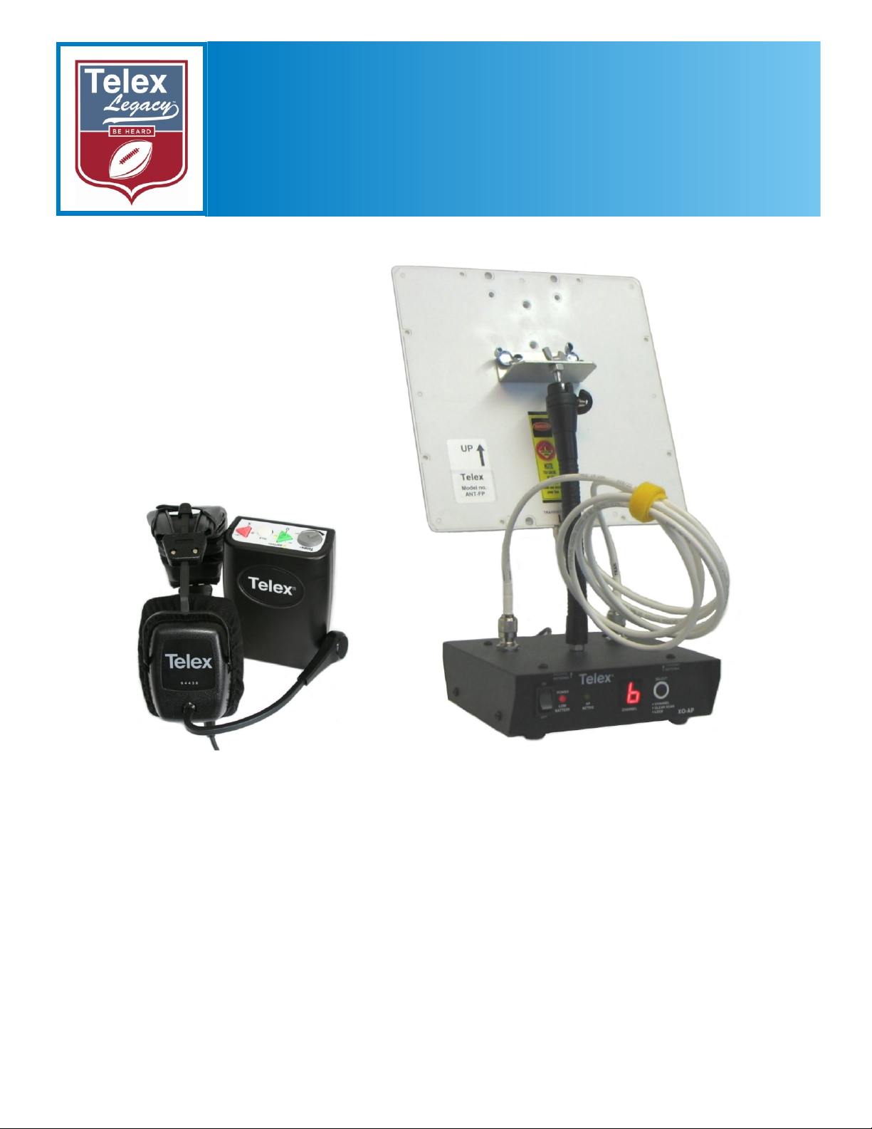
Wireless Intercom System
XO-AP
XO-1
Wireless Intercom System
Telex®
Telex Communications, Inc.
Page 2

Table of Contents
Section 1 Introduction 1-1
General Description .............................................................................................................1-1
System Features ...................................................................................................................1-1
Section 2 XO-AP Base Station 2-1
Controls and Connections....................................................................................................2-1
Section 3 XO-1 Beltpack 3-1
Controls and Connections....................................................................................................3-1
Section 4 Specifications 4-1
Legacy Technical Specifications .........................................................................................4-1
Section 5 Operation 5-1
Set-up...................................................................................................................................5-1
System Operation.................................................................................................................5-1
Halftime ...............................................................................................................................5-3
Before the Next Use (Charging Instructions)......................................................................5-3
Long Term Storage ..............................................................................................................5-3
Li-Ion Batteries....................................................................................................................5-4
Section 6 Encryption Code 6-1
Encryption Code ..................................................................................................................6-1
Logging into a Beltpack (XO-1)..........................................................................................6-1
Beltpack Options .................................................................................................................6-2
Enter new password......................................................................................................6-2
Enter new encryption key .............................................................................................6-2
Exit ...............................................................................................................................6-2
Section 7 Trouble Shooting 7-1
Section 8 RF Channels 8-1
RF Channels.........................................................................................................................8-1
Section 9 Regulatory Information 9-1
Regulatory Information .......................................................................................................9-1
Section 10 Accessories and Replacement Parts 10-1
Page 3

Section 1 - Introduction
General Description
The Telex Legacyä Series is a full duplex
(simultaneous talk and listen), multi-channel, wireless
intercom system. Legacy offers a complete solution
for 2 to 7 coaches per sideline, fast and easy set-up,
durable beltpacks, 64 bit audio encryption, and
professional grade headsets.
The main components of the Legacyä series consists
of the XO-1 beltpack and the XO-AP base station.
The XO-1 beltpack offers the user two separate audio
channels and the ability to communicate on both
channels at the same time. The user can talk and listen
on these channels or just turn off the talk button and
listen only. The beltpack uses an internal rechargeable
Li-Ion battery that will provide up to 8 hours of
uninterrupted operation.
The XO-AP base station can support up to seven XO-1
beltpacks. The base station provides a central relay
location which handles the audio traffic between
beltpacks. The built-in base station intelligence called
ClearScan™ automatically selects the best RF (Radio
Frequency) channel for communications on start-up.
The base station also uses an internal rechargeable
Li-Ion battery that will provide up to 10 hours of
uninterrupted operation.
System Features
• Easy base station and beltpack setup.
• Uses mature 2.4GHz IEEE 802.11 Wireless LAN
Technology.
• Audio in the system is encrypted via a 64 bit DES
algorithm.
• Base station automatically selects the clearest RF
channel for the system, and sets the system on that
channel. No user intervention is needed.
• Easy to read base station LED display to indicate the
RF channel of the system.
• If desired, the user can select any one of the eleven
standard 802.11 channels for the system to operate
via a single button on the XO-AP front panel.
• Durable, water resistant, ABS, beltpack cases.
• Dependable, rechargeable, wide temperature range,
Li-Ion batteries.
• Low battery indications on the beltpack and base
station.
• Base station can be powered from external AC or
internal battery.
1-1
Page 4
ON
OFF
RECEIVE
ANTENNA
POWER
LOW
BATTERY
AP
ACTIVE
CHANNEL
TRANSMIT
ANTENNA
SELECT
CHANNEL
CLEAR SCAN
LOCK
XO-AP
Telex
1
3
2 4
5
6
7
8
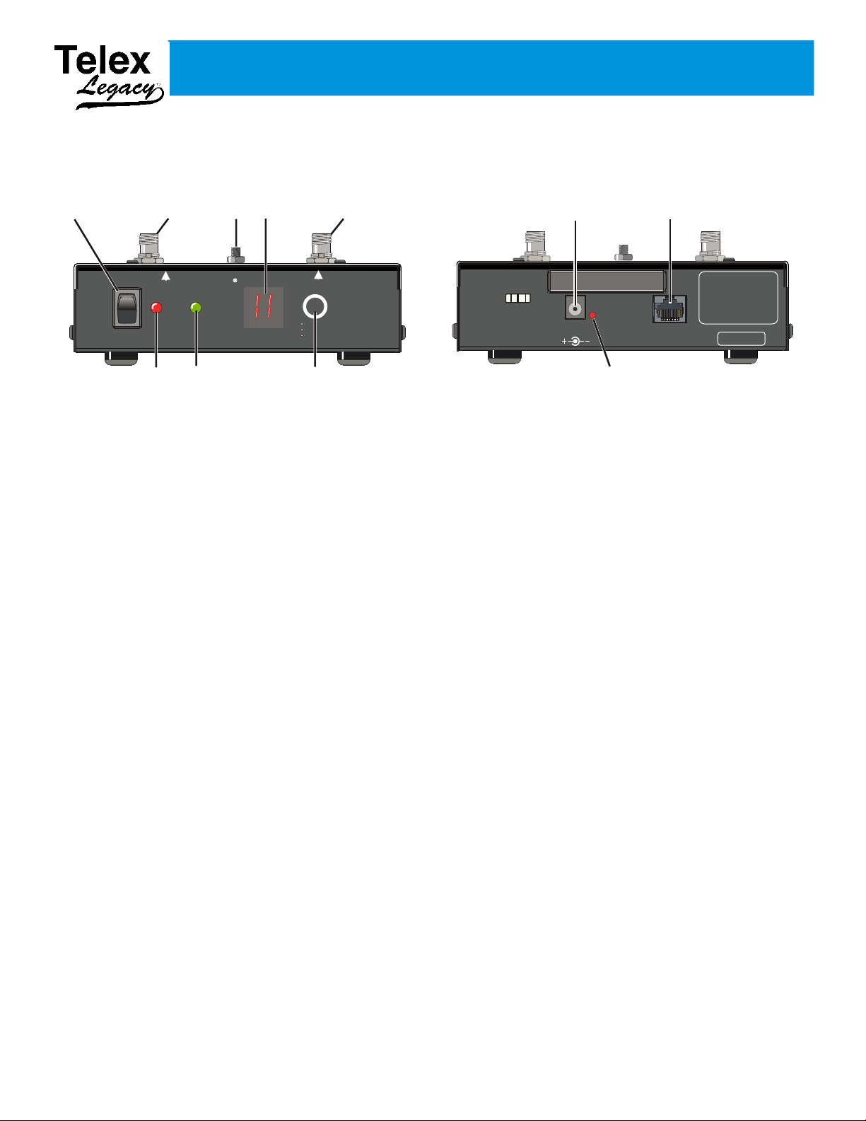
Section 2 - XO-AP Base Station
CORD
RETAINER
12 VDC
400mA
RED: CHARGING
GREEN: READY
PGM
9
10
11
Controls and Connections
Front View
1. On/Off Switch – Turns the power on/off to the base
station.
2. Power / Low Battery Light – Indicates the base
station has power, either from the internal battery or
external power connected to the unit.
Battery Indication:
• GREEN - Battery OK
• RED - Battery Low (needs charged)
3. Transmit Antenna Jack – This reverse TNC jack is
where the transmit antenna coaxial cable should be
connected.
4. AP Active Light – This green light flashing indicates
that the AP has successfully booted and is operating.
5.
Gooseneck Antenna Mount Lug - Provides
attachment point for the gooseneck antenna mount.
6. RF Channel Display – Indicates the RF channel the
unit is set on.
Rear View
8. Select Button – Press the button to select the desired
RF channel for the base station.
• ClearScan – Press and hold the button until the
decimal point starts to flash (about 3 seconds)
then release. The unit will examine the RF
channels available, then select the one with the
least activity and set the AP on that channel.
• Lock – Press and hold the button until the
decimal point is on solid (about 10 seconds)
then release. The AP will be locked on the
channel displayed. To unlock, press and hold
the button again until the decimal point is off.
Lock makes the currently displayed channel
difficult for a user to accidentally change.
9. Charge Jack – Used to charge the internal battery or
power the unit directly off a wall outlet. Accepts a
5.5mm x 2.5mm plug with the center positive. Must be
supplied with a 12VDC regulated power supply with at
least a 400mA current capacity.
10.
Charge Light.
7. Receive Antenna Jack – This reverse TNC jack is
where the receive antenna coaxial cable should be
connected.
2-1
• RED = Battery is charging.
• GREEN = Battery is charged.
11.
Programming Jack – This RJ-45 jack is used for
programming the unit at the factory.
Page 5
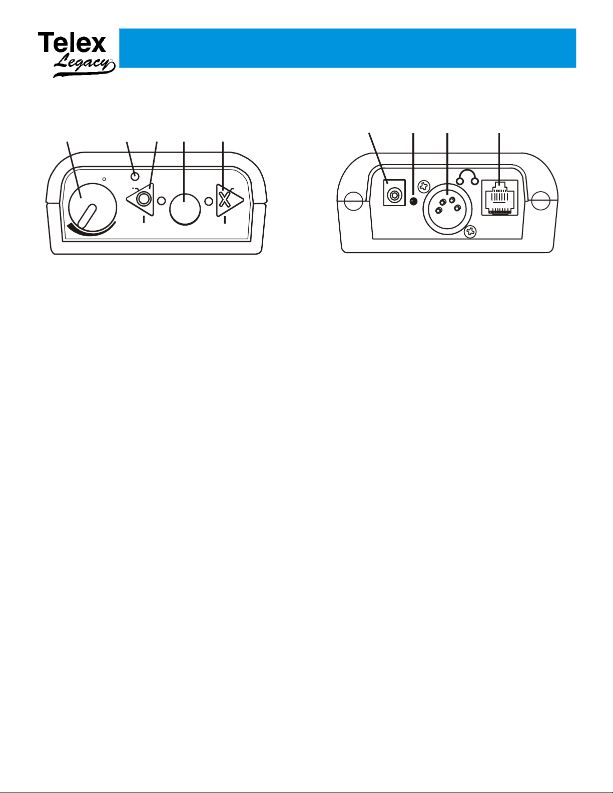
Section 3 - XO-1 Beltpack
Telex
R
MIC
OFF
BATTERY
TAL K
MIC +
X
O
1 2
3
4
5
CHG
EXT
6
7
8
9
Controls and Connections
Top View
On/Off & Volume Control – Turns the beltpack
1.
power on/off and controls headset volume.
2. Battery Light –
• GREEN - Battery OK
• RED - Battery Low (needs charged)
3. "O" Channel Button and Light – Selects the
“Offense” intercom channel. The light next to the
button will light when selected. Also controls headset
Mic (-) level:
• Mic (-): press and hold talk button, then press and
hold "O" button. Listen for voice prompts in headset.
Adjust headset mic level lower (-).
4. Talk Button – When pressed the microphone path is
enabled. This button has two operational modes:
• Momentary – Pressed and hold for over ½ second.
Bottom View
7. Charge Light.
• RED = Beltpack battery is charging.
• GREEN = Beltpack battery is charged.
8.
Headset Connector – Standard 4-pin XLR connector.
• Pin 1 = Microphone GND
• Pin 2 = Microphone HOT
• Pin 3 = Headphone +
• Pin 4 = Headphone –
9. Programming Jack – This RJ-45 jack is used for
programming the unit at the factory. It can also be used
for changing the user’s password and encryption code.
• Latch on/off – Tap button and the microphone path
is enabled. Tap again to turn off.
5. "X" Button and Light – Selects the “Defense”
intercom channel. The light next to the button will light
when selected. Also controls headset mic (+) level:
• Mic (+): Press and hold talk button, then press and
hold "X" button. Listen for voice prompts in headset.
Adjust headset mic level higher (+).
6. Charge Jack – Used to charge the internal battery.
Accepts a 5.5mm x 2.5mm plug with the center
positive. Must be supplied with a 12VDC regulated
power supply with at least a 400mA current capacity.
3-1
Page 6

Section 4 - Specifications
Legacyä Technical Specifications
RF Technology............................................................................................................IEEE 802.11 (WiFi)
Frequency Band of Operation ......................................................................................2.412 to 2.462 GHz
FCC License ..............................................................................................................No License Required
Encryption Technology.............................................................64 bit (DES) Digital Encryption Standard
Audio Frequency Range................................................................................400 Hz to 5500 Hz (+/- 1dB)
Dynamic Range................................................................................................................................>75 dB
Beltpack Headset Output ............................................................200 mW into 300 Ohms (1% Distortion)
Beltpack Microphone Gain Adjustment .....................................................10 Levels with Voice Prompts
Antenna (XO-1) .................................................................................................................Internal Dipoles
Antenna (XO-AP)............................................................................................11dBi Dual Patch Antenna
(Transmit vertically Polarized, Receive horizontally polarized)
XO-AP (Base Station) Battery ..........................................................................Lithium-Ion Rechargeable
XO-AP Battery Life............................................................................................................10 Hr (Typical)
XO-AP Recharge Time ........................................................................................................8 Hr (Typical)
XO-AP Low Battery Indication....................................................30 minutes of battery life left (Typical)
XO-1 (Beltpack) Battery ...................................................................................Lithium-Ion Rechargeable
XO-1 Battery Life.................................................................................................................8 Hr (Typical)
XO-1 Recharge Time............................................................................................................6 Hr (Typical)
XO-1 Low Battery Indication .......................................................15 minutes of battery life left (Typical)
XO-AP (Base Station)Size.........................6.00” L x 6.40” W x 2.00” H (15.24cm x 16.26cm x 5.08cm)
XO-AP Weight...................................................................................................................2 lb 3 oz (992g)
XO-1 Size.....................................................5.25” L x 3.75” W x 1.68” H (13.33cm x 9.53cm x 4.27cm)
XO-1 Weight .........................................................................................................................12.5oz (354g)
Carry Case Size....................................23.50” L x 8.50” W x 20.50” H (59.70cm x 21.60cm x 52.07cm)
Carry Case Weight ......................................................(Not Loaded with Equipment)12 lb 8 oz (5.44 kg)
4-1
Page 7

Section 5 - Operation
Point antenna toward
your Sideline.
XO-AP in the
Press Box
Set-up
Prior to use, the XO-1 beltpacks and the XO-AP base
station need to have their battery packs fully charged.
Refer to the charging instructions of this section for
instructions on charging.
1. Place the XO-AP base station in the area of use.
2. Attached the two antenna cables from the antenna
to the XO-AP. The cable marked, “Receive”
connects to the receive jack on the XO-AP. The
cable marked, “Transmit” connects to the transmit
jack on the XO-AP. The front label of the XO-AP
indicates the RF (Radio Frequency) connector
designation.
4. Plug the XO-AP’s external power supply into an
AC outlet if available. If external power is not
available then the XO-AP can run off internal
battery (if already charged).
Front View
Rear View
Figure 5-3
XO-AP Base Station
System Operation
Figure 5-1
XO-AP and Panel Antenna
Aim the directional panel antenna at the area of
3.
beltpack use. For example, in Figure 5-2, the
XO-AP is used in a football application where the
XO-AP is located in the press box and the antenna
is pointed toward the near side coach’s box.
NOTE: Make sure the antenna’s path to the area of
coverage has clear line-of-sight.
1. Turn on the XO-AP by pressing the power switch
into the On position. The XO-AP must be
powered-up before any beltpacks are turned on.
The following turn on events should follow:
• The power light on the front panel will activate
immediately.
• After 20 seconds the;
° AP active light will turn on solid.
° Channel indicator will illuminate all
segments of the display.
° The power light will turn red then back to
green.
• The XO-AP will then initiate a clear scan of the
11 RF channels of the 2.4 GHz spectrum (will
take about 4 seconds).
• The XO-AP will finally place the unit on the
clearest RF channel and indicate it has finished
booting by flashing the AP active light.
Figure 5-2
XO-AP with Antenna Pointing Toward Near
Sidelinde
5-1
Page 8

2. You can now scan for another channel, manually
select a channel or lock the current channel by
using one of the following procedures:
4. Wear the beltpack on the hip. Place them in a
position that allows for greatest visibility to the
XO-AP antenna in the press box.
• Clear Scan – Hold the <SELECT> button until
the decimal point starts to blink (about 3
seconds) then release. The XO-AP will scan all
available channels and then set itself to the
clearest channel available for use.
• Manual Set – Press the button to <SELECT>
the XO-AP channel desired. Each press of the
button will increment the channel by one. Once
the desired channel is displayed the XO-AP will
automatically set to that channel.
• Lock – Press and hold the <SELECT> button
until the decimal point is on solid (about 10
seconds) then release. The XO-AP is now
locked on that RF channel. The only two ways
to unlock it are to reboot the XO-AP or hold the
<SELECT> button down again until the
decimal point turns from solid to off (about 10
seconds).
5. XO-1 Top Panel Buttons – The XO-1 has three top
panel buttons:
• TALK – This button enables/disables the
beltpack’s microphone.
Enabled - The audio channel light(s) are on
solid and sidetone (your own voice heard in
your headphones) can be heard.
Disabled – The audio channel light(s) blink and
there is no sidetone.
Talk has two modes of operation:
° Latch – Tap the button to enable the
microphone and talk on the currently
selected audio channel(s). Tap again to
disable the microphone.
° Momentary – Press and hold the
button. The microphone will be enabled
immediately and momentary mode will start
if it is held over a ½ second. In this mode, the
microphone is only active for as long as the
button is held down.
Top View
Bottom View
Figure 5-4
XO-1 Beltpack
3. With the XO-AP running, turn on the XO-1
beltpacks one at a time. The following turn on
events should follow:
• The battery light will activate immediately.
• After 20 seconds;
° A voice in the headphone will say, “wireless”
indicating the beltpack is in wireless mode
(as opposed to “wired” mode used for
changing the encryption code, see section 6).
° The “O” light will lite and communications
will start.
• "O" – Tap the button to listen or talk to the
offense audio channel. The light next to it will
activate when selected.
• "X" – Tap the button to listen or talk to the
offense audio channel. The light next to it will
activate when selected.
6. The default for the microphone gain is level four,
which is adequate for most events, however, the
microphone gain can be adjusted up or down if
desired.
• Adjusting the XO-1 Microphone Gain
° Place the headset on.
° Once the beltpack has finished booting, press
<O> and hold the <TALK> button.
° As holding the <TALK> button, press the
and hold the <O> button for less gain, hold
the <X> button for more gain.
° There are ten levels of microphone gain.
Each indicated by a voice prompt. Level 4 is
the default.
5-2
Page 9

° Release the “O” or “X” button, and the
<TALK> button when at the desired level.
• The higher the microphone gain the louder that
beltpack user’s voice will sound to other users
and themselves.
Halftime
1. During halftime leave the XO-AP base station
“On”.
2. The XO-1 beltpacks may be turned off for halftime
to conserve battery life, or left on.
3. If the XO-1 beltpacks are turned off at halftime,
turn the beltpacks on, one at a time. Again, the
beltpack’s battery light will indicate immediately,
but the unit will require up to 20 seconds to
complete start-up.
Before the Next Use
(Charging Instructions)
After an event the XO-AP base station will need to
charge for at least 10 – 14 hours.
The XO-AP may be left on charge indefinitely.
Long Term Storage
“Long term storage” of the system is defined as no
use of the system for 1 month or longer. Due to the
internal Li-Ion batteries of the XO-1 and XO-AP,
care should be taken in long term storage. Use the
following steps to ensure the best performance of
the system after it comes out of storage.
1. After the last event or game of the season:
• If the XO-1 or XO-AP batteries were used for
four hours or less then do not recharge the
internal XO-1 or XO-AP batteries. (Please see
the discussion of “Li-Ion batteries” in the follow
part of this section as to why)
1. Ensure the XO-1 beltpacks are in the “OFF”
position.
2. Ensure the XO-AP base station is in the “OFF””
position.
3.
XO-1 Beltpack: Plug the XO-1 beltpack charger
into the charge jack on the bottom of the beltpack.
The beltpack should be charged in a room
temperature location. The LED on the bottom of
the unit indicates the charge status.
• RED = Charging
• GREEN = Charging Done
After an event the XO-1 beltpack will need to
charge for at least 6 – 8 hours.
The beltpacks may be left on charge indefinitely.
4.
XO-AP base station: Plug the XO-AP battery
charger into the charge jack on the bottom of the
beltpack. The base station should be charged in a
room temperature location. The LED on the
bottom of the unit indicates the charge status.
• RED = Charging
• If the XO-1 or XO-AP batteries were used for
more then four hours then recharge the internal
XO-1 or XO-AP batteries for two hours then
take them off charge (Please see the discussion
of Li-Ion batteries in the follow part of this
section as to why)
2. Store the XO-1's and XO-AP in a clean, cool, dry
location away from heat. The temperature of the
storage location should not rise above room
temperature. The recommended temperature range
of the storage location is 32 - 77° F (0 – 25° C).
3. Every 6 months charge the XO-AP and XO-1 for
three hours then take off charge. Do not fully
charge. This prevents the battery from
over-discharging and helps maintain the battery’s
performance.
• GREEN = Charging Done
5-3
Page 10

Li-Ion Batteries
The Li-Ion batteries used in the XO-1 and XO-AP are
excellent batteries for portable, outdoor applications.
They have a high energy density (energy per weight)
compare to other rechargeable battery technologies
(NiCd, NiMH, Alkaline, Gel Cells), are low
maintenance, and offer superior performance at low
temperatures.
For best performance after long-term storage, Telex
recommends the batteries be charged to 30% - 50% of
capacity before being placed in storage. This is the
typical battery capacity left after a sporting event, such
as a football game. Li-Ion batteries retain nearly all
their capacity, after longterm storage, if stored in dry,
cool temperatures with only 30% to 50% charge. They
can lose up to 20% capacity if stored for long term
right after being fully charged.
It is also a good idea to charge the XO-AP and XO-1
batteries once every 6 months for three hours then take
off charge. Do not fully charge. This helps to maintain
the battery's performance and prevent any
over-discharging.
5-4
Page 11

Section 6 - Encryption Code
Encryption Code
The Legacy system uses a 64 bit DES (Digital
Encryption Standard) encryption algorithm to encrypt
all audio in the system. The beltpacks in the system
have a “key” in the software that the algorithm uses as
the basis for the encryption. The same “key” must be
used in all beltpacks on the system for communication
to occur. The base station only relays the audio, and as
such, does not need any encryption code set. The
beltpack key can be anything from numbers to
sentences to hexadecimal letters. For example the
phrase, “The legacy system works great for our
coaches”, could be the “key” for the encryption. The
only criteria is the phrase/numbers/letters be no more
than 80 characters long (this includes spaces and
punctuation).
The following instructions use Telnet and Windows®
2000 to log into the beltpack. Other applications and
operating systems will be similar.
1. Unplug any current RJ-45 network connections
from the computer.
2.
With the mouse, right click the My Network
Places con, then select Properties.
3.
Select Local Area Connection and then right
click. Select Properties.
4.
Select Internet Protocol (TCP/IP) and click on
the Properties button.
This encryption is active on all units from the factory
and does not have to be “turned on” by the user. The
user may want to change their key to something
unique. This may be done by following the steps
below:
Logging into a Beltpack (XO-1)
Computer Requirements:
Hardware
• Monitor
• Keyboard & Mouse
• Network card (10 BaseT or 100 BaseT)
• Ethernet straight thru or crossover cable (Use
the green cable supplied with the system.)
Operating System
Microsoft® Windows® 95/98, NT, 2000, XP
Software
Telnet or similar application that lets you
communicate to a specified IP Address (Most
all computers have telnet or a similar program
installed on them by default).
5.
Now select “Use the following IP address:”
option. Make a note of your current settings on this
screen (so you can place them back when done
logging into the beltpacks).
Enter the following:
a. IP address: 192.168.1.40
b. Subnet Mask: 255.255.255.0
c. Default gateway: 192.168.1.1
6.
Once the above information is entered, hit the OK
button. Hit the OK button on the next screen out if
needed. Depending on your computer, you may
need to reboot the computer for the IP address
changes to take effect.
7. Plug one end of the supplied green Ethernet cable
into the computer.
8. Start a “command prompt” console window by
clicking on “Start” then moving the mouse arrow
to Programs, then Accessories and finally clicking
on “Command Prompt”.
6-1
Page 12

Press and hold down the “X” button on the
9.
beltpack. Keep holding the “X” button and turn-on
the beltpack. Hold the beltpack button down until
the green LED next to the “X” button lights up
(about 20 seconds), then release button (Places the
beltpack in programming mode).
Enter new password
1.
This option allows the user to change this XO-1’s
password. The default from the factory is legacy. The
user is never allowed to change the login name of
telex.
10. Plug the other end of the Ethernet cable into the
beltpack.
11. Type, telnet 192.168.1.X at the computer’s
command prompt, then press <ENTER>. Fill in
for X the last digit of the IP address that is on the
back label on the XO-1.
12. After about 20 seconds the beltpack will respond
with a login request. Enter the following:
Login: telex <ENTER>
Password: legacy <ENTER>
NOTE: The password entry does not give user
feedback to the screen.
NOTE: If the computer says, “failed to connect”, turn
off the XO-1, check computer settings, and go back to
step 6.
2. Enter new encryption key
The user must change the encryption key if this option
is selected.
1. When “2” is selected the phrase, “Enter new
encryption key” appears.
2. Now enter the new encryption key. The
maximum length is 80 characters. Any
combination of letters/numbers/punctuation
may be used. Even a sentence such as, “My
offensive is number 1 in the state”, may be
used as the key. The key is upper and lower
case sensitive.
NOTE: A character is letters, numbers,
punctuation, spaces, etc.
NOTE: The “backspace” keyboard button may
not work on all computers using Telnet, use the
delete button instead if this is the case.
Beltpack Options
Once successfully logged into the beltpack you will be
presented with the following screen:
The three options on this screen are as follows:
CAUTION: Write down the key or use one
that you can remember, because ALL
beltpacks must have the same key entered in
order for communication.
3. Press <ENTER> after the key is typed. This
will place the key in the software. Reboot
the beltpack for the new encryption key to
take effect.
3. Exit
This exits the login and closes the connection to the
beltpack.
6-2
Page 13

Section 7 - Troubleshooting
Please reread the operation and encryption section of this manual
to make sure you have completed system set-up properly. The
following contains troubleshooting tips that may be helpful in
solving the problem.
Problem Possible Cause Solution
When the XO-AP power switch was
turned on, the unit's power light came on
but the system never booted-up after 25
seconds
Can't change the RF channel the XO-AP
is on.
When the XO-AP power switch was
turned on nothing happens. The power
light does not light.
• Internal battery is nearly exhausted.
• On boot, an error was encountered and
the unit could not finish boot-up
• The base station may be set to channel
lock. This is indicated by a solid
decimal point in the bottom right of the
display.
• Internal battery is completely
exhausted.
If you are unable to solve the problem, contact the manufacturer
or dealer from whom you purchased the system for assistance.
• Charge the battery or run off external
AC power.
• Power down the XO-AP, wait two
seconds, then power-up again.
• Hold the <SELECT> button down for
about 10 seconds. This unlocks the RF
channel lock button. A user could also
reboot the XO-AP, but the beltpacks
would need to be turned off until the
XO-AP finished booting, then turned
on.
• Plug the AC power plug into the
XO-AP. Allow the unit at least 5
minutes for the internal battery to
receive an initial charge. Then turn the
unit on and run it off AC power.
RF range of all the beltpacks is less than
normal.
• Antenna is not connected to the
XO-AP.
• The two antenna connections are not
connected to the right connectors on the
XO-AP.
• WiFi RF interference has occurred.
• Non-WiFi RF Interference has
occurred.
7-1
• Connect the antenna to the XO-AP.
Make sure the correct cable of the
antenna goes to the corresponding
connector on the XO-AP. The XO-AP
front label indicates the transmit and
receive connectors.
• The XO-AP front label indicates the
transmit and receive connectors. The
antenna's cables are labeled as to their
connection point.
• Press and hold the <SELECT> button
for 3 seconds (until the decimal point
flashes), then release. The unit will do a
clear scan and place itself on the
clearest channel. The beltpacks do not
have to be turned off, they will follow
the XO-AP to the new channel within a
few seconds after the clear scan is done.
• Manually select a different RF channel
by hitting the <SELECT> button. Make
sure the new channel is at least several
channels away from the old channel for
the best chance of avoiding the RF
interference. The beltpacks do not have
to be turned off, they will follow the
XO-AP to the new channel after a few
seconds.
Page 14

Section 7 - Troubleshooting continued
Problem Possible Cause Solution
When the XO-1 beltpack power was
turned on, the unit's power light came
up, but the "O" button light never came
up and communication never started.
Headphone audio from another
beltpack(s) is loud and distorted.
Headphone audio from another
beltpack(s) is too low.
• Internal battery is nearly exhaused.
• On boot, an error was encountered and
the unit could not finish boot-up
• Microphone gain on the other
beltpack(s) is set to high.
• The headset's microphone on the other
beltpack(s) is too far from the user's
mouth.
• Microphone gain on the other
beltpack(s) is set too low.
• Charge the battery.
• Power down the XO-1, wait two
seconds, then power-up again.
• Press and hold the <TALK> button on
the offending beltpack. While holding
the <TALK> button, press and hold
the "O" button to lower microphone
gain. The factory setting is at the voice
prompt "four" level.
• Adjust the headset's microphone on the
suspected beltpack so it is one index
finger width straight out from the
user's mouth.
• Press and hold the <TALK> button on
the suspected beltpack. While holding
the <TALK> button, press and hold
the "X" button to raise the microphone
gain. The factory setting is at the voice
prompt "four" level.
7-2
Page 15

Section 8 - RF Channels
1 2 3 4 5 6 7 8 9 10 11
Channel Numbers
1
2
3
4
5
6
7
8
9
10
11
2.412
2.422
2.432
2.442
2.452
2.462
2.472
2.417 2.427
2.437
2.447
2.457 2.467
Channel Center Frequencies (in GHz)
22 MHz
Channel Bandwidth
XO-1 & XO-AP RF Channelization Scheme
802.11 RF Channels
The Legacy system has the ability to operate on any
one of eleven RF channels. Although there are several
different frequency channel settings, there is overlap
between the channels. There are three
non-overlapping channels available in the FCC
regulatory domain. When choosing frequency
channels for systems in the vicinity of each other, you
should choose frequency channels that do not overlap
(e.g. Channels 1, 6, and 11).
8-1
Page 16

Section 9 - Regulatory Information
Regulatory Information
The XO-1 and XO-AP comply with Part 15 of FCC
rules and Canada RSS-210. Operation is subject to the
following conditions:
1. This device may not cause harmful interference.
2. This device must accept any interference received,
including interference that may cause undesired
operation.
3. Use only the manufacturer or dealer supplied
antenna(s), beltclips and/or accessories for this
device.
4. The XO-AP base station complies with FCC
radiation exposure limits set forth for an
uncontrolled environment. The antennas used with
this equipment should be installed and operated
with a minimum distance of 20cm between the
antenna and your body.
5. This device and its antenna(s) must not be
co-located or operated in conjunction with any
other antenna or transmitter.
To assure continued compliance with FCC
regulations, any changes or modification not expressly
approved by the party responsible for compliance
could void the user’s authority to operate this
equipment.
9-1
Page 17

Section 10 - Accessories and Replacement Items
Model Number Part Number Description
LP-XO1 301950002
PH-1 64438100LG
PH-2 644371000LG
HR-1 300534007LG
XO-1 Beltpack and Battery
Charger.
NOTE: User must provide
XO-AP serial number and IP
address of all XO-1/XO-APs in
system with order.
Single sided w/flexible dynamic
boom mic, 150 ohm earphone,
6" (1.8m) cord and A4F
connector
Dual sided w/flexible dynamic
boom mic, 150 ohm earphone, 6'
(1.8M) cord and A4F connector
Single sided w/flexible dynamic
boom mic, 150 ohm earphone,
5" (1.5M) cord and A4F
connector.
HR-2 300534000LG
PH-100 301581007LG
PH-200 301581002LG
Dual sided w/flexible dynamic
boom mic, 150 ohm earphone,
5" (1.5M) cord and A4F
connector.
Single sided w/flexible dynamic
boom mic, 150, ohm earphone,
5" (1.5M) cord, and A4f
Connecotr
Dual sided w/flexible dynamic
boom mic, 150 ohm earphone,
5" (1.5M) cord and A4F
connector
10-1
Page 18

Section 10 - Accessories and Replacement Items Continued
Model Number Part Number Description
ANT-FP 302054001
ANT-FPM 302054000
XOB 302054002
Dual Diversity, Flat Patch
Antenna with Dual Coax, 11dBi
Metal Tilt and Swivel Antenna
Mounting bracket for ANT-FP
Antenna. Use for permanent
mount of ANT-FP Flat Panel
Antenna.
Nylon Belt, Adjustable
10-2
Page 19

8601 East Cornhusker Highway, Lincoln, NE 68507
Made in U.S.A. PN 804233-TX
 Loading...