


Telex |
Operating Instructions |
RadioCom™ |
BTR-80N, TR-80N, TR-82N |
Professional |
Wireless |
Intercom System |
R |
Table of Contents
1. Introduction
General Description . . . . . . . . . . . . . . . . . . . . . . . . . . . . . . . . . . . . . . . . . . . . . . . . . . . . . . . . . . . . . . . . . . . . . . . . 1-1
System Features . . . . . . . . . . . . . . . . . . . . . . . . . . . . . . . . . . . . . . . . . . . . . . . . . . . . . . . . . . . . . . . . . . . . . . . . . . . 1-1
2. BTR-80N Base Controls and Connections
Front Panel . . . . . . . . . . . . . . . . . . . . . . . . . . . . . . . . . . . . . . . . . . . . . . . . . . . . . . . . . . . . . . . . . . . . . . . . . . . . . . . 2-1
Rear Panel . . . . . . . . . . . . . . . . . . . . . . . . . . . . . . . . . . . . . . . . . . . . . . . . . . . . . . . . . . . . . . . . . . . . . . . . . . . . . . . . 2-2
BTR-80N Specifications . . . . . . . . . . . . . . . . . . . . . . . . . . . . . . . . . . . . . . . . . . . . . . . . . . . . . . . . . . . . . . . . . . . . . 2-3
3. TR-80N Controls and Connections
Top Panel . . . . . . . . . . . . . . . . . . . . . . . . . . . . . . . . . . . . . . . . . . . . . . . . . . . . . . . . . . . . . . . . . . . . . . . . . . . . . . . . 3-1
Rear Panel . . . . . . . . . . . . . . . . . . . . . . . . . . . . . . . . . . . . . . . . . . . . . . . . . . . . . . . . . . . . . . . . . . . . . . . . . . . . . . . . 3-2
TR-80N Specifications . . . . . . . . . . . . . . . . . . . . . . . . . . . . . . . . . . . . . . . . . . . . . . . . . . . . . . . . . . . . . . . . . . . . . . 3-3
4. TR-82N Beltpack Controls and Connections
Top Panel . . . . . . . . . . . . . . . . . . . . . . . . . . . . . . . . . . . . . . . . . . . . . . . . . . . . . . . . . . . . . . . . . . . . . . . . . . . . . . . . 4-1
Rear Panel . . . . . . . . . . . . . . . . . . . . . . . . . . . . . . . . . . . . . . . . . . . . . . . . . . . . . . . . . . . . . . . . . . . . . . . . . . . . . . . . 4-2
TR-82N Specifications . . . . . . . . . . . . . . . . . . . . . . . . . . . . . . . . . . . . . . . . . . . . . . . . . . . . . . . . . . . . . . . . . . . . . . 4-3
5. Initial Set-Up
Unpacking . . . . . . . . . . . . . . . . . . . . . . . . . . . . . . . . . . . . . . . . . . . . . . . . . . . . . . . . . . . . . . . . . . . . . . . . . . . . . . . . 5-1
Antennas . . . . . . . . . . . . . . . . . . . . . . . . . . . . . . . . . . . . . . . . . . . . . . . . . . . . . . . . . . . . . . . . . . . . . . . . . . . . . . . . . 5-2
Antenna Connection. . . . . . . . . . . . . . . . . . . . . . . . . . . . . . . . . . . . . . . . . . . . . . . . . . . . . . . . . . . . . . . . . . 5-2
Antenna Polarization . . . . . . . . . . . . . . . . . . . . . . . . . . . . . . . . . . . . . . . . . . . . . . . . . . . . . . . . . . . . . . . . . 5-2
Distance Between Antennas. . . . . . . . . . . . . . . . . . . . . . . . . . . . . . . . . . . . . . . . . . . . . . . . . . . . . . . . . . . . 5-2
Antenna Placement. . . . . . . . . . . . . . . . . . . . . . . . . . . . . . . . . . . . . . . . . . . . . . . . . . . . . . . . . . . . . . . . . . . 5-2
Improving Reception/Increasing Range. . . . . . . . . . . . . . . . . . . . . . . . . . . . . . . . . . . . . . . . . . . . . . . . . . . 5-4
6. BTR-80N Operation
Basic Operational Description . . . . . . . . . . . . . . . . . . . . . . . . . . . . . . . . . . . . . . . . . . . . . . . . . . . . . . . . . . . . . . . . 6-1
System Quick Start. . . . . . . . . . . . . . . . . . . . . . . . . . . . . . . . . . . . . . . . . . . . . . . . . . . . . . . . . . . . . . . . . . . 6-1
Interfacing to the BTR-80N
Transmit and Receive Antennas. . . . . . . . . . . . . . . . . . . . . . . . . . . . . . . . . . . . . . . . . . . . . . . . . . . . . . . . . 6-2
2-Wire Intercom Ports . . . . . . . . . . . . . . . . . . . . . . . . . . . . . . . . . . . . . . . . . . . . . . . . . . . . . . . . . . . . . . . . 6-2
4-Wire Intercom Ports . . . . . . . . . . . . . . . . . . . . . . . . . . . . . . . . . . . . . . . . . . . . . . . . . . . . . . . . . . . . . . . . 6-3
Auxiliary Input / Output . . . . . . . . . . . . . . . . . . . . . . . . . . . . . . . . . . . . . . . . . . . . . . . . . . . . . . . . . . . . . . 6-3
Stage Announce (SA) Relay . . . . . . . . . . . . . . . . . . . . . . . . . . . . . . . . . . . . . . . . . . . . . . . . . . . . . . . . . . . 6-4
Base Station Link . . . . . . . . . . . . . . . . . . . . . . . . . . . . . . . . . . . . . . . . . . . . . . . . . . . . . . . . . . . . . . . . . . . . 6-4
WTA Audio . . . . . . . . . . . . . . . . . . . . . . . . . . . . . . . . . . . . . . . . . . . . . . . . . . . . . . . . . . . . . . . . . . . 6-5
CAN Bus . . . . . . . . . . . . . . . . . . . . . . . . . . . . . . . . . . . . . . . . . . . . . . . . . . . . . . . . . . . . . . . . . . . . . 6-5
Program Jack . . . . . . . . . . . . . . . . . . . . . . . . . . . . . . . . . . . . . . . . . . . . . . . . . . . . . . . . . . . . . . . . . . . . . . . 6-5
Powering the Base Station . . . . . . . . . . . . . . . . . . . . . . . . . . . . . . . . . . . . . . . . . . . . . . . . . . . . . . . . . . . . . . . . . . . 6-6
Start-Up Screen . . . . . . . . . . . . . . . . . . . . . . . . . . . . . . . . . . . . . . . . . . . . . . . . . . . . . . . . . . . . . . . . . . . . . . . . . . . . 6-6
Status Screen . . . . . . . . . . . . . . . . . . . . . . . . . . . . . . . . . . . . . . . . . . . . . . . . . . . . . . . . . . . . . . . . . . . . . . . . . . . . . . 6-6
RSSI Screen . . . . . . . . . . . . . . . . . . . . . . . . . . . . . . . . . . . . . . . . . . . . . . . . . . . . . . . . . . . . . . . . . . . . . . . . . . . . . . 6-6
Group / Channel Selection . . . . . . . . . . . . . . . . . . . . . . . . . . . . . . . . . . . . . . . . . . . . . . . . . . . . . . . . . . . . . . . . . . . 6-7
Group / Channel Select . . . . . . . . . . . . . . . . . . . . . . . . . . . . . . . . . . . . . . . . . . . . . . . . . . . . . . . . . . . . . . . 6-7
Group / Frequency Select. . . . . . . . . . . . . . . . . . . . . . . . . . . . . . . . . . . . . . . . . . . . . . . . . . . . . . . . . . . . . . 6-7
Frequency Edit (User-Defined Groups Only) . . . . . . . . . . . . . . . . . . . . . . . . . . . . . . . . . . . . . . . . . . . . . . 6-7
Base Main Settings . . . . . . . . . . . . . . . . . . . . . . . . . . . . . . . . . . . . . . . . . . . . . . . . . . . . . . . . . . . . . . . . . . . . . . . . . 6-8
Talk Button. . . . . . . . . . . . . . . . . . . . . . . . . . . . . . . . . . . . . . . . . . . . . . . . . . . . . . . . . . . . . . . . . . . . . . . . . 6-8
Channel Select Button . . . . . . . . . . . . . . . . . . . . . . . . . . . . . . . . . . . . . . . . . . . . . . . . . . . . . . . . . . . . . . . . 6-8
Local Headset Volume and Gain . . . . . . . . . . . . . . . . . . . . . . . . . . . . . . . . . . . . . . . . . . . . . . . . . . . . . . . . 6-8
Base Transmit Power . . . . . . . . . . . . . . . . . . . . . . . . . . . . . . . . . . . . . . . . . . . . . . . . . . . . . . . . . . . . . . . . . 6-8
Squelch Settings . . . . . . . . . . . . . . . . . . . . . . . . . . . . . . . . . . . . . . . . . . . . . . . . . . . . . . . . . . . . . . . . . . . . . 6-9
Stage Announce Level . . . . . . . . . . . . . . . . . . . . . . . . . . . . . . . . . . . . . . . . . . . . . . . . . . . . . . . . . . . . . . . . 6-9
Antenna Power. . . . . . . . . . . . . . . . . . . . . . . . . . . . . . . . . . . . . . . . . . . . . . . . . . . . . . . . . . . . . . . . . . . . . . 6-9
CAN Bus Number . . . . . . . . . . . . . . . . . . . . . . . . . . . . . . . . . . . . . . . . . . . . . . . . . . . . . . . . . . . . . . . . . . 6-10
-i-
Table of Contents (continued)
Intercom Settings . . . . . . . . . . . . . . . . . . . . . . . . . . . . . . . . . . . . . . . . . . . . . . . . . . . . . . . . . . . . . . . . . . . . . . . . . 6-10 i. 2-Wire Intercom . . . . . . . . . . . . . . . . . . . . . . . . . . . . . . . . . . . . . . . . . . . . . . . . . . . . . . . . . . . . . . . . . . 6-10 ii. 4-Wire Intercom . . . . . . . . . . . . . . . . . . . . . . . . . . . . . . . . . . . . . . . . . . . . . . . . . . . . . . . . . . . . . . . . . . 6-11
Auxiliary Settings . . . . . . . . . . . . . . . . . . . . . . . . . . . . . . . . . . . . . . . . . . . . . . . . . . . . . . . . . . . . . . . . . . . . . . . . . 6-11
ClearScan . . . . . . . . . . . . . . . . . . . . . . . . . . . . . . . . . . . . . . . . . . . . . . . . . . . . . . . . . . . . . . . . . . . . . . . . . . . . . . . 6-12
Lockout . . . . . . . . . . . . . . . . . . . . . . . . . . . . . . . . . . . . . . . . . . . . . . . . . . . . . . . . . . . . . . . . . . . . . . . . . . . . . . . . . 6-12
Copy . . . . . . . . . . . . . . . . . . . . . . . . . . . . . . . . . . . . . . . . . . . . . . . . . . . . . . . . . . . . . . . . . . . . . . . . . . . . . . . . . . . 6-12
1st Use Default . . . . . . . . . . . . . . . . . . . . . . . . . . . . . . . . . . . . . . . . . . . . . . . . . . . . . . . . . . . . . . . . . . . . . . . . . . . 6-12
Factory Reset . . . . . . . . . . . . . . . . . . . . . . . . . . . . . . . . . . . . . . . . . . . . . . . . . . . . . . . . . . . . . . . . . . . . . . . . . . . . 6-12 Connection of Multiple Base Stations with Link Cables . . . . . . . . . . . . . . . . . . . . . . . . . . . . . . . . . . . . . . . . . . . 6-13 Over-the-Air Data Links . . . . . . . . . . . . . . . . . . . . . . . . . . . . . . . . . . . . . . . . . . . . . . . . . . . . . . . . . . . . . 6-13 Master and Servant Base Stations . . . . . . . . . . . . . . . . . . . . . . . . . . . . . . . . . . . . . . . . . . . . . . . . . . . . . . 6-14 CAN Bus . . . . . . . . . . . . . . . . . . . . . . . . . . . . . . . . . . . . . . . . . . . . . . . . . . . . . . . . . . . . . . . . . . . . . . . . . 6-15 Base Station Link Configurations . . . . . . . . . . . . . . . . . . . . . . . . . . . . . . . . . . . . . . . . . . . . . . . . . . . . . . 6-15 Wireless Talk Around (WTA) Audio Only . . . . . . . . . . . . . . . . . . . . . . . . . . . . . . . . . . . . . . . . . . 6-16 WTA and a Single Can Bus Network . . . . . . . . . . . . . . . . . . . . . . . . . . . . . . . . . . . . . . . . . . . . . . 6-17 WTA and Several CAN Bus Networks . . . . . . . . . . . . . . . . . . . . . . . . . . . . . . . . . . . . . . . . . . . . . 6-18
7. TR-80N / TR-82N Operation
Basic Operational Description . . . . . . . . . . . . . . . . . . . . . . . . . . . . . . . . . . . . . . . . . . . . . . . . . . . . . . . . . . . . . . . . 7-1 System Quick Start. . . . . . . . . . . . . . . . . . . . . . . . . . . . . . . . . . . . . . . . . . . . . . . . . . . . . . . . . . . . . . . . . . . 7-1 Battery Installation . . . . . . . . . . . . . . . . . . . . . . . . . . . . . . . . . . . . . . . . . . . . . . . . . . . . . . . . . . . . . . . . . . . . . . . . . 7-2 Headset Connection . . . . . . . . . . . . . . . . . . . . . . . . . . . . . . . . . . . . . . . . . . . . . . . . . . . . . . . . . . . . . . . . . . . . . . . . 7-3 Sidetone . . . . . . . . . . . . . . . . . . . . . . . . . . . . . . . . . . . . . . . . . . . . . . . . . . . . . . . . . . . . . . . . . . . . . . . . . . . . . . . . . 7-3 Antenna Connections . . . . . . . . . . . . . . . . . . . . . . . . . . . . . . . . . . . . . . . . . . . . . . . . . . . . . . . . . . . . . . . . . . . . . . . 7-3 TR-80N Beltpack . . . . . . . . . . . . . . . . . . . . . . . . . . . . . . . . . . . . . . . . . . . . . . . . . . . . . . . . . . . . . . . . . . . . . . . . . . 7-4 ON/Off Volume Control. . . . . . . . . . . . . . . . . . . . . . . . . . . . . . . . . . . . . . . . . . . . . . . . . . . . . . . . . . . . . . . 7-4 BAT/Peak Light . . . . . . . . . . . . . . . . . . . . . . . . . . . . . . . . . . . . . . . . . . . . . . . . . . . . . . . . . . . . . . . . . . . . . 7-4 Talk Button. . . . . . . . . . . . . . . . . . . . . . . . . . . . . . . . . . . . . . . . . . . . . . . . . . . . . . . . . . . . . . . . . . . . . . . . . 7-4 Audio Channel Select Button. . . . . . . . . . . . . . . . . . . . . . . . . . . . . . . . . . . . . . . . . . . . . . . . . . . . . . . . . . . 7-4 Stage Announce (SA). . . . . . . . . . . . . . . . . . . . . . . . . . . . . . . . . . . . . . . . . . . . . . . . . . . . . . . . . . . . . . . . . 7-4 Group and Channels. . . . . . . . . . . . . . . . . . . . . . . . . . . . . . . . . . . . . . . . . . . . . . . . . . . . . . . . . . . . . . . . . . 7-5 Transmit Frequency . . . . . . . . . . . . . . . . . . . . . . . . . . . . . . . . . . . . . . . . . . . . . . . . . . . . . . . . . . . . . . . . . . 7-5 Receive Frequencies . . . . . . . . . . . . . . . . . . . . . . . . . . . . . . . . . . . . . . . . . . . . . . . . . . . . . . . . . . . . . . . . . 7-6 Microphone Gain . . . . . . . . . . . . . . . . . . . . . . . . . . . . . . . . . . . . . . . . . . . . . . . . . . . . . . . . . . . . . . . . . . . . 7-6 Battery Display . . . . . . . . . . . . . . . . . . . . . . . . . . . . . . . . . . . . . . . . . . . . . . . . . . . . . . . . . . . . . . . . . . . . . 7-6 Transmit Power . . . . . . . . . . . . . . . . . . . . . . . . . . . . . . . . . . . . . . . . . . . . . . . . . . . . . . . . . . . . . . . . . . . . . 7-7 Squelch Screen . . . . . . . . . . . . . . . . . . . . . . . . . . . . . . . . . . . . . . . . . . . . . . . . . . . . . . . . . . . . . . . . . . . . . . 7-8 Transmit Mode . . . . . . . . . . . . . . . . . . . . . . . . . . . . . . . . . . . . . . . . . . . . . . . . . . . . . . . . . . . . . . . . . . . . . . 7-8 LEDs Off/On . . . . . . . . . . . . . . . . . . . . . . . . . . . . . . . . . . . . . . . . . . . . . . . . . . . . . . . . . . . . . . . . . . . . . . . 7-8 Software Version/Band . . . . . . . . . . . . . . . . . . . . . . . . . . . . . . . . . . . . . . . . . . . . . . . . . . . . . . . . . . . . . . . 7-8 ClearScanTM . . . . . . . . . . . . . . . . . . . . . . . . . . . . . . . . . . . . . . . . . . . . . . . . . . . . . . . . . . . . . . . . . . . . . . . . 7-9 Lock Out . . . . . . . . . . . . . . . . . . . . . . . . . . . . . . . . . . . . . . . . . . . . . . . . . . . . . . . . . . . . . . . . . . . . . . . . . . 7-9 1st Use Default. . . . . . . . . . . . . . . . . . . . . . . . . . . . . . . . . . . . . . . . . . . . . . . . . . . . . . . . . . . . . . . . . . . . . . 7-9 Factory Reset . . . . . . . . . . . . . . . . . . . . . . . . . . . . . . . . . . . . . . . . . . . . . . . . . . . . . . . . . . . . . . . . . . . . . . . 7-9 RF Monitor Screen. . . . . . . . . . . . . . . . . . . . . . . . . . . . . . . . . . . . . . . . . . . . . . . . . . . . . . . . . . . . . . . . . . . 7-9 Setting Beltpack ID . . . . . . . . . . . . . . . . . . . . . . . . . . . . . . . . . . . . . . . . . . . . . . . . . . . . . . . . . . . . . . . . . 7-10
TR-82N Beltpack . . . . . . . . . . . . . . . . . . . . . . . . . . . . . . . . . . . . . . . . . . . . . . . . . . . . . . . . . . . . . . . . . . . . . . . . . 7-11
On/Off Volume Control . . . . . . . . . . . . . . . . . . . . . . . . . . . . . . . . . . . . . . . . . . . . . . . . . . . . . . . . . . . . . . 7-11
BAT/Peak Light . . . . . . . . . . . . . . . . . . . . . . . . . . . . . . . . . . . . . . . . . . . . . . . . . . . . . . . . . . . . . . . . . . . . 7-11
Talk Buttons . . . . . . . . . . . . . . . . . . . . . . . . . . . . . . . . . . . . . . . . . . . . . . . . . . . . . . . . . . . . . . . . . . . . . . . 7-11
Audio Channel Select Button . . . . . . . . . . . . . . . . . . . . . . . . . . . . . . . . . . . . . . . . . . . . . . . . . . . . . . . . . . 7-11
Stage Announce (SA). . . . . . . . . . . . . . . . . . . . . . . . . . . . . . . . . . . . . . . . . . . . . . . . . . . . . . . . . . . . . . . . 7-11
Wireless Talk Around (WTA) . . . . . . . . . . . . . . . . . . . . . . . . . . . . . . . . . . . . . . . . . . . . . . . . . . . . . . . . . 7-11
Group and Channels. . . . . . . . . . . . . . . . . . . . . . . . . . . . . . . . . . . . . . . . . . . . . . . . . . . . . . . . . . . . . . . . . 7-12
Transmit Frequency . . . . . . . . . . . . . . . . . . . . . . . . . . . . . . . . . . . . . . . . . . . . . . . . . . . . . . . . . . . . . . . . . 7-12
-ii-
Table of Contents (continued)
Receive Frequencies . . . . . . . . . . . . . . . . . . . . . . . . . . . . . . . . . . . . . . . . . . . . . . . . . . . . . . . . . . . . . . . . 7-13 Microphone Gain . . . . . . . . . . . . . . . . . . . . . . . . . . . . . . . . . . . . . . . . . . . . . . . . . . . . . . . . . . . . . . . . . . . 7-13 Battery Display . . . . . . . . . . . . . . . . . . . . . . . . . . . . . . . . . . . . . . . . . . . . . . . . . . . . . . . . . . . . . . . . . . . . 7-13 Transmit Power . . . . . . . . . . . . . . . . . . . . . . . . . . . . . . . . . . . . . . . . . . . . . . . . . . . . . . . . . . . . . . . . . . . . 7-14 Squelch Screen . . . . . . . . . . . . . . . . . . . . . . . . . . . . . . . . . . . . . . . . . . . . . . . . . . . . . . . . . . . . . . . . . . . . . 7-15 Transmit Mode . . . . . . . . . . . . . . . . . . . . . . . . . . . . . . . . . . . . . . . . . . . . . . . . . . . . . . . . . . . . . . . . . . . . . 7-15 Headphone Options . . . . . . . . . . . . . . . . . . . . . . . . . . . . . . . . . . . . . . . . . . . . . . . . . . . . . . . . . . . . . . . . . 7-15 Auxiliary Input. . . . . . . . . . . . . . . . . . . . . . . . . . . . . . . . . . . . . . . . . . . . . . . . . . . . . . . . . . . . . . . . . . . . . 7-15 LEDs Off/On . . . . . . . . . . . . . . . . . . . . . . . . . . . . . . . . . . . . . . . . . . . . . . . . . . . . . . . . . . . . . . . . . . . . . . 7-15 Software Version/Band . . . . . . . . . . . . . . . . . . . . . . . . . . . . . . . . . . . . . . . . . . . . . . . . . . . . . . . . . . . . . . 7-16 ClearScanTM . . . . . . . . . . . . . . . . . . . . . . . . . . . . . . . . . . . . . . . . . . . . . . . . . . . . . . . . . . . . . . . . . . . . . . . 7-16 Lock Out . . . . . . . . . . . . . . . . . . . . . . . . . . . . . . . . . . . . . . . . . . . . . . . . . . . . . . . . . . . . . . . . . . . . . . . . . 7-16 1st Use Default. . . . . . . . . . . . . . . . . . . . . . . . . . . . . . . . . . . . . . . . . . . . . . . . . . . . . . . . . . . . . . . . . . . . . 7-16 Factory Reset . . . . . . . . . . . . . . . . . . . . . . . . . . . . . . . . . . . . . . . . . . . . . . . . . . . . . . . . . . . . . . . . . . . . . . 7-16 RF Monitor Screen. . . . . . . . . . . . . . . . . . . . . . . . . . . . . . . . . . . . . . . . . . . . . . . . . . . . . . . . . . . . . . . . . . 7-17 Setting Beltpack ID . . . . . . . . . . . . . . . . . . . . . . . . . . . . . . . . . . . . . . . . . . . . . . . . . . . . . . . . . . . . . . . . . 7-17
8. BTR-80N Menu Structure . . . . . . . . . . . . . . . . . . . . . . . . . . . . . . . . . . . . . . . . . . . . . . . . . . . . . . . . . . . 8-1
9. TR-80N Menu Structure. . . . . . . . . . . . . . . . . . . . . . . . . . . . . . . . . . . . . . . . . . . . . . . . . . . . . . . . . . . . . 9-1
10. TR-82N Menu Structure. . . . . . . . . . . . . . . . . . . . . . . . . . . . . . . . . . . . . . . . . . . . . . . . . . . . . . . . . . . . 10-1
11. Frequency Bands . . . . . . . . . . . . . . . . . . . . . . . . . . . . . . . . . . . . . . . . . . . . . . . . . . . . . . . . . . . . . . . . . . 11-1
Band Pairings . . . . . . . . . . . . . . . . . . . . . . . . . . . . . . . . . . . . . . . . . . . . . . . . . . . . . . . . . . . . . . . . . . . . . . . . . . . . 11-1
Frequency Plan . . . . . . . . . . . . . . . . . . . . . . . . . . . . . . . . . . . . . . . . . . . . . . . . . . . . . . . . . . . . . . . . . . . . . . . . . . . 11-2
12. Trouble Shooting . . . . . . . . . . . . . . . . . . . . . . . . . . . . . . . . . . . . . . . . . . . . . . . . . . . . . . . . . . . . . . . . . . 12-1
13. Battery Information . . . . . . . . . . . . . . . . . . . . . . . . . . . . . . . . . . . . . . . . . . . . . . . . . . . . . . . . . . . . . . . . 13-1
14. 2 -Wire Intercom Specifications. . . . . . . . . . . . . . . . . . . . . . . . . . . . . . . . . . . . . . . . . . . . . . . . . . . . . . 14-1
15. Certification Information . . . . . . . . . . . . . . . . . . . . . . . . . . . . . . . . . . . . . . . . . . . . . . . . . . . . . . . . . . . 15-1
FCC . . . . . . . . . . . . . . . . . . . . . . . . . . . . . . . . . . . . . . . . . . . . . . . . . . . . . . . . . . . . . . . . . . . . . . . . . . . . . . . . . . . 15-1
Canada . . . . . . . . . . . . . . . . . . . . . . . . . . . . . . . . . . . . . . . . . . . . . . . . . . . . . . . . . . . . . . . . . . . . . . . . . . . . . . . . . 15-1
Europe . . . . . . . . . . . . . . . . . . . . . . . . . . . . . . . . . . . . . . . . . . . . . . . . . . . . . . . . . . . . . . . . . . . . . . . . . . . . . . . . . 15-2
BTR-80N EC Declaration of Conformity . . . . . . . . . . . . . . . . . . . . . . . . . . . . . . . . . . . . . . . . . . . . . . . . . . . 15-3
TR-80N EC Declaration of Conformity. . . . . . . . . . . . . . . . . . . . . . . . . . . . . . . . . . . . . . . . . . . . . . . . . . . . . 15-4
TR-82N EC Declaration of Conformity. . . . . . . . . . . . . . . . . . . . . . . . . . . . . . . . . . . . . . . . . . . . . . . . . . . . . 15-5
16. Accessories and Replacement Parts. . . . . . . . . . . . . . . . . . . . . . . . . . . . . . . . . . . . . . . . . . . . . . . . . . . 16-1
-iii-
General Description
Telex RadioCom™ BTR-80N UHF Synthesized Wireless In- tercom system offers reliable, high-performance, high-fidelity full-duplex communications delivered with minimum spec- trum usage.
The BTR-80N system includes the BTR-80N frequency agile base station, working with up to four TR-80N or TR-82N fre- quency agile beltpacks operating in full-duplex communica- tions. An almost unlimited number of beltpacks may be used with a base station if the beltpacks are in Push-to-Tx mode (half-duplex).
The BTR-80N system incorporates two audio channel opera- tion, permitting the beltpack operator to choose between two separate audio channels of communication, with the base sta- tion tracking the beltpack selection. This allows the user the flexibility to create a party-line and a private line within the same beltpack.
The BTR-80N system is perfectly suited for stand-alone oper- ation and can also interface with Audiocom® (Telex), RTS® TW, Clear-Com®, as well as RTS®, Matrix systems and other 4-wire intercom systems. In addition to the external intercom systems interfaces listed above, the system provides connec- tions for auxiliary balanced audio input and output, as well as wireless talk-around (WTA) and stage announce (SA) fea- tures.
The RadioCom™ BTR-80N system has been designed for re- liable, efficient operation. Operating in the 482 to 722 MHz range the units operate reliably at line-of-sight distances of 1,000 feet. With available antenna systems from Telex, the ef- fective operating range can be extended. The high-efficiency beltpacks provide between 8 and 11 hours of uninterrupted op- eration using NiMH rechargeable battery packs.
Section
1
Introduction
•ClearScan™ function on base station and beltpack to automatically find the best channels on which to operate.
•Full-duplex (simultaneous talk and listen) or Push-to-TX (half-duplex) operation.
•Compatible with Audiocom® (Telex), RTS® TW, Matrix, Clear-Com® , and other wired intercom types.
•Two independent channels of intercom audio with the ability to operate partyline and RTS Matrix on the same
intercom channel at the same time.
•WTA (Wireless Talk Around) beltpack control. This feature allows beltpacks to talk to each other, but their audio is
lifted from any wired system connected to the base station.
•SA (Stage Announce) beltpack control. Allows the user to direct their audio to a jack on the back of the base for P.A.
systems or other external audio systems.
•Relay contact closure on the base when the SA button is pressed.
•TR-82N features two audio channel binaural operation in either stereo or mono mode.
•TR-82N has 1/8 inch (3.5mm) jack for auxiliary input from another audio source, such as an IFB, iPod®, or
other similar device.
•Beltpack units contained in a weather and shock resistant die cast magnesium case.
•Convenient IEC power connector on the base station so the unit can plug directly to outlets. No in-line or wall
plug power supply.
•Base station has option for DC on the receive coaxial cable line for powering in-line low noise amps.
•Dark mode settable on TR-80N and TR-82N beltpacks. This shuts down all LEDS.
System Features
•Frequency-agile base station and beltpacks. No external computer/device required to select frequencies.
•Backlit base-station LCD allows the user to easily monitor the beltpack’s status as well as change base station fre-
quencies.
•Squelch adjust on BTR-80N and TR-80N, TR-82N beltpacks.
•Beltpack's battery level displayed on the base station and in beltpack's menus.
RTS® and Audiocom® are registered trademarks of Telex Communications, Inc. Clear-Com® is a registered trademark of Clear-Com Intercom Systems, Inc iPod® is a registered trademark of Apple Inc..
1-1
Section
2
BTR-80N Base Station
Controls and Connections - Front Panel
2 |
3 |
4 |
5 |
6 |
7 |
8 |
10 |
|
MENU |
BTR-80N |
UP |
|
|
|
|
|
|
|
CHANNEL |
|
|
|
PORTABLE STATION CONNECT |
INPUTS |
|
|
|||||||
|
|
|
|
|
|
|
|
SELECT |
ON/PEAK |
|||
|
ClearScan |
|
1 |
2 |
3 |
4 |
|
|
|
|
1 |
TALK |
|
|
2 |
1 |
2 |
|
2 |
|
|||||
|
|
|
|
|
|
1 |
AUX |
|
||||
POWER |
SET |
COPY |
DOWN |
|
|
4 WIRE |
|
|
2 WIRE |
|
|
|
|
|
|
|
|
|
|
|
|
||||
1 |
9 |
11 |
12 |
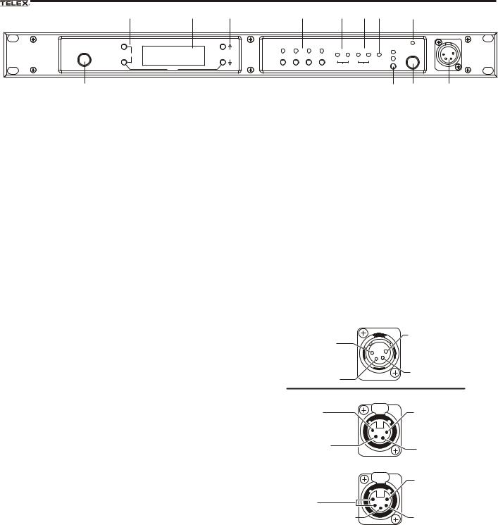
Figure 2-1
BTR-80N - Front Panel
1.Power switch – Do not power-up a base station within 3 seconds of the unit being turned off. Voltages within the unit need to drop below a threshold before being re-pow- ered. If powerd-up in less than 3 seconds, the unit may boot as the wrong frequency band.
Even with the unit powered down via the power switch there are some circuits within the base that are energized. To completely remove power to the unit, the power cord must be disconnected.
2.[Menu] and [Set] buttons – Used to select menus and set options on the LCD.
3.Backlit Graphics LCD (Liquid Crystal Display).
4.[Up] and [Down] buttons – Used to select base station
10.Talk/Peak Light – LED is green when talk button #11 is active. A normal mic gain setting will cause the LED to flash red on the loudest speech levels. If the gain is too high, the LED will be red at normal speech volumes.
11.Talk Button – Press to enable the audio path from the local headset. LED #10 will turn green when enabled. A quick press and release latches button on. If the talk function is latched on, pressing the talk button again will turn it off.
12.Local Headset Connector – Male XLR connector for Telex units, Female XLR connector for RTS units. A dynamic or electret headset microphone is automatically detected. Microphone gain and volume are settable in the software menus.
options on the LCD.
5.Portable Station Connect – Buttons used to enable or disable the respective receiver’s audio. GREEN LED = Audio enabled, LED OFF = Audio disabled.
|
Telex Units |
(1) Microphone |
(4) Headphone |
Shield (-) |
Low (-) |
(2) Microphone |
(3) Headphone |
Audio (+) |
High (+) |
6.4-wire Selection/Peak Input Indicators - Displays when 4-wire intercoms are active with a green indication. A red indication means the intercom input level is too high.
7.2-Wire Selection/Peak Input Indicators - Displays which 2-wire intercoms are active with a green indication. A red indication means the intercom input level is too high.
8.Auxiliary Selection/Peak Input indicator - Displays if auxiliary input is 'ON" with a green indication. A red indication means the intercom input level is too high
(4) Headphone |
|
RTS Units |
Low (-) |
PUSH |
(1) Microphone |
|
||
|
|
Shield (-) |
(3) Headphone |
|
|
High (+) |
|
(2) Microphone |
|
|
Audio (+) |
|
PUSH |
(1) Microphone |
|
|
|
(5) (4) Headphone |
|
Shield (-) |
Low (-) |
|
|
(3) Headphone |
|
(2) Microphone |
High (+) |
|
Audio (+) |
9. Headset Intercom Select – Controls the intercom to
Figure 2-2
which the local headset is connected. Each press of the
Local Headset Wiring
button changes the connection; channel 1, channel 2, both.
2-1
Controls and Connections - Rear Panel
1 |
4 |
5 |
6 |
7 |
8 |
11 |
BTR-80N |
BASE STATION |
INTERCOM 1 |
|
INTERCOM 2 |
|
AUXILIARY |
STAGE |
|
|
|
|
|
|
LINK |
2 WIRE |
|
2 WIRE |
|
AUDIO |
ANNOUNCE |
100-240 VAC 50-60 Hz |
1/2 |
T |
|
|
|
L |
|
L |
|
|
12-15 VDC |
|
|
R |
|
|
IN |
O |
|
O |
|
|
3.5 A |
|
|
A |
|
PROGRAM |
O |
4 WIRE |
O |
4 WIRE |
|
MADE IN U.S.A. |
|
|
N |
|
RELAY |
|
P |
P |
|
|
|
|
S |
|||
CONTACT |
|
|
T |
|
T |
|
|
|
|
|
M |
RECEIVE |
|
|
H |
|
H |
|
|
|
|
|
I |
|
|
|
R |
|
R |
|
|
|
|
2 |
|
|
|
OUT |
U |
|
U |
|
|
|
|
T |
|
|
|
|
|
|
|
INPUT |
OUTPUT |
OUTPUT |
Telex Communications, Inc. |
|
|
2 |
3 |
9 |
10 |
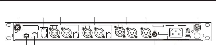
Figure 2-3
BTR-80N - Rear Panel
1.Receive Antenna - Female “TNC” Connector. Color band on antenna must match color dot on base station.
2.Relay Contact – A dry contact closure which is activated when a beltpack user presses the stage announce (SA) button. Normally Open (NO). The rating is one amp at 24V maximum.
3.Program Connector - Used to update software in unit.
4.Base Station Link Jacks – When multiple base stations are connected through this jack, it allows wireless talk around (WTA) audio from the beltpacks to be routed from system to system. Also will allow CAN bus data to be passed between base stations.
5.Intercom 1 – Interface to wired intercom channel 1.
2-Wire – Male and female 3-pin XLR connectors wired in parallel. The connectors are switched to the appropriate intercom configuration via software.
4-Wire – An RJ-11 type jack compatible with “Matrix” type intercom systems.
6. Intercom 2 – Interface to wired intercom channel 2.
2-Wire – Male and female 3-pin XLR connectors wired in parallel. The connectors are switched to the appropriate intercom configuration via software.
4-Wire – An RJ-11 type jack compatible with “Matrix” type intercom systems.
7.Auxiliary Input/Output – One 3-pin female XLR/ 1/4 inch combination input connector and one 3-pin male XLR output connector.
8.Stage Announce Output – Passes the audio from any of the base station’s beltpacks that have selected stage announce (SA).
9.DC Input Jack – Accepts 12-15 VDC (5.5mm by 2.5mm screw on plug), 3.5 Amps to power base station from a DC source. Base may be connected to DC and AC source at the same time. If AC source fails the base will automatically switch to DC power. Inside the base there is a user replaceable fuse in-line with the DC input jack. This fuse is a 5A, 250V, 5x20mm, fast acting ceramic cartridge fuse.
10.Power – IEC receptacle. Accepts 100 – 240 VAC, 1A maximum, 50 – 60 Hz.
11.Transmit Antenna - Female “TNC” Connector. Color band on antenna must match color dot on base station.
2-2

BTR-80N
Specifications
Overall
RF Frequency Range . . . . . . . . . . . . . . . . . . . . . . . . . . . . . . 482 - 608 MHz, 614 - 722 MHz, in 18 MHz TX and RX bands (Some frequencies only available in certain countries)
Power Requirements . . . . . . . . . . . . . . . . . . . . . . . . . . . . . . . . . . . . . . . . . . . . . . . 100-240 VAC, 50-60 Hz, IEC receptacle DC Only . . . . . . . . . . . . . . . . . . . . . . . . . . . . . . . . . . . . . . . . . . . . . . . . . . . . . . . . . . . . . . . . . . . . . . 12 - 15 VDC, 3.5 Amps Temperature Range . . . . . . . . . . . . . . . . . . . . . . . . . . . . . . . . . . . . . . . . . . . . . . . . . . . . . . -4° F to 130° F (-20° C to 55° C) Dimensions . . . . . . . . . . . . . . . . . . . . . . . . . . . . . . . . . . . . . 19.00” W x 1.72” H x 14.00” D (48.3 cm x 4.4 cm x 35.6 cm) Weight . . . . . . . . . . . . . . . . . . . . . . . . . . . . . . . . . . . . . . . . . . . . . . . . . . . . . . . . . . . . . . . . . . . . . . . . . . . 7 lbs 2 oz (3.24 kg) TX Antenna . . . . . . . . . . . . . . . . . . . . . . . . . . . . . . . . . . . . . . . . . . . . . . . . . . . . . ½ Wave (supplied), TNC Male Connector RX Antenna . . . . . . . . . . . . . . . . . . . . . . . . . . . . . . . . . . . . . . . . . . . . . . . . . . . . . ½ Wave (supplied), TNC Male Connector FCC ID:. . . . . . . . . . . . . . . . . . . . . . . . . . . . . . . . . . . . . . . . . . . . . . . . . . . . . . . . . . . . . . . . . B5DM528 (TX 482-608 MHz) Frequency Response . . . . . . . . . . . . . . . . . . . . . . . . . . . . . . . . . . . . . . . . . . . . . . . . . . . . . . . . . . . . . . . . . . . . . 200Hz-4kHz Four Wire Input . . . . . . . . . . . . . . . . . . . . . . . . . . . . . . . . . . . . . . . . . . . . . . . . . . . . . . . . Level Adjustable (2 Vrms typical) Four Wire Output . . . . . . . . . . . . . . . . . . . . . . . . . . . . . . . . . . . . . . . . . . . . . . . . . . . . . . . Level Adjustable (2 Vrms typical) Telex Intercom . . . . . . . . . . . . . . . . . . . . . . . . . . . Input/Output Level Adjustable (1 Vrms typical), Line impedance 300Ω RTS Intercom . . . . . . . . . . . . . . . . . . . . . . . . . Input/Output Level Adjustable (0.775 Vrms typical), Line Impedance 200Ω Clear-Com® Intercom . . . . . . . . . . . . . . . . . . . . . Input/Output Level Adjustable (1 Vrms typical), Line Impedance 200Ω Auxiliary Input . . . . . . . . . . . . . . . . . . . . . . . . . . . . . . . . . . . . . . . . . . . . . . . . . . . . . . . . . . . . . . Adjustable (2 Vrms typical) Auxiliary Output . . . . . . . . . . . . . . . . . . . . . . . . . . . . . . . . . . . . . . . . . . . . . . . . . . . . Adjustable (2 Vrms typical into 600Ω) Stage Announce Output . . . . . . . . . . . . . . . . . . . . . . . . Internally Adjustable (2 Vrms typical at rated deviation into 600Ω) Stage Announce Relay . . . . . . . . . . . . . . . . . . . . . . . . . . . . . . . . . . . . . . . . . . . . . . . Dry contact, rated at 1 Amp, 24V Max Microphone input sensitivity . . . . . . . . . . . . . . . . . . . . . . . . . . . . . . . . . . . . . . . . . . . . . . . . . . . . . . . . . . . . . . . . . . . . . 9mV Local Headset Output . . . . . . . . . . . . . . . . . . . . . . . . . . . . . . . . . . . . . . . . . . . . . . 40mW output into 600Ω (1% Distortion)
Transmitter
Type. . . . . . . . . . . . . . . . . . . . . . . . . . . . . . . . . . . . . . . . . . . . . . . . . . . . . Two Synthesized Transmitters, 720 channels each Transmit Power (each transmitter) . . . . . . . . . . . . . . . . . . . . . . . . . . . . Selectable: off, 10 mW, 50 mW, 100 mW, 249 mW Modulation Type. . . . . . . . . . . . . . . . . . . . . . . . . . . . . . . . . . . . . . . . . . . . . . . . . . . . . . . . . . . . . . . . . . . . . . . . . . . . . . . . FM Deviation. . . . . . . . . . . . . . . . . . . . . . . . . . . . . . . . . . . . . . . . . . . . . . . . . . . . . . . . . . . . . . . . . . . . . . . . . . . . . . . . . . . . 4 kHz RF Frequency Stability . . . . . . . . . . . . . . . . . . . . . . . . . . . . . . . . . . . . . . . . . . . . . . . . . . . . . . . . . . . . . . . . . . . . . . . 2.5 PPM Modulation Limiter . . . . . . . . . . . . . . . . . . . . . . . . . . . . . . . . . . . . . . . . . . . . . . . . . . . . . . . . Peak-Responding Compressor Radiated Harmonics & Spurious . . . . . . . . . . . . . . . . . . . . . . . . . . . . . . . . . . . . . . . . . . . . . . . . Exceeds FCC specifications
Receiver
Type . . . . . . . . . . . . . . . . Triple Conversion Superheterodyne, four Independent Synthesized IFs, FM, 720 channels each RF Sensitivity . . . . . . . . . . . . . . . . . . . . . . . . . . . . . . . . . . . . . . . . . . . . . . . . . . . . . . . . . . . . . . . <0.6 µV for 12 dB SINAD Squelch Threshold . . . . . . . . . . . . . . . . . . . . . . . . . . . . . . . . . . . . . . . . . . . . . . . . . . . . adjustable - 12 / 20 / 24 dB SINAD IF Selectivity . . . . . . . . . . . . . . . . . . . . . . . . . . . . . . . . . . . . . . . . . . . . . . . . . . . . . . . . . . . . . . . . 6 dB at 30 kHz Bandwidth Image Rejection . . . . . . . . . . . . . . . . . . . . . . . . . . . . . . . . . . . . . . . . . . . . . . . . . . . . . . . . . . . . . . . . . . . . . . . 70 dB or better Squelch Quieting. . . . . . . . . . . . . . . . . . . . . . . . . . . . . . . . . . . . . . . . . . . . . . . . . . . . . . . . . . . . . . . . . . . . . . . . . . . . . . 90 dB RF Frequency Stability . . . . . . . . . . . . . . . . . . . . . . . . . . . . . . . . . . . . . . . . . . . . . . . . . . . . . . . . . . . . . . . . . . . . . . . 2.5 PPM
2-3
2-4 Blank
Section
3
TR-80N Beltpack
Controls and Connections - Top Panel
1 |
2 |
|
4 |
5 |
6 |
|
|
|
R |
|
|
|
|
WTA |
1 2 |
BAT/PK TALK |
|
|
OFF |
SA |
|
|
7 |
|
|
|
|
|
|
VOL |
|
|
CHANNEL |
TALK |
|
3
Figure 3-1
TR-80N Top Panel
1.On/Off & Volume Control – Turns the beltpack power on and controls headset volume.
2.Wireless Talk Around (WTA) – When pressed, the user’s audio is disconnected from the wired intercom, auxiliary input/output and the base station’s local headset. Other beltpack users, on that audio channel, can hear the user as normal. The button activates the nearby red LED as well as the talk button.
3.Stage Announce (SA) –When pressed, the user’s audio is routed to the stage announce connector on the back of the base station. The user also loses their sidetone as an indication that stage announce is activated. The other wireless beltpacks and wired users do not hear the user’s audio. The button is non-latching and activates the nearby red LED as well as the talk button.
4.Audio Channel Select Button – Allows user to select either audio channel 1or 2.
5.Bat/Peak Light (BAT/PK) – Light will flash once when unit is turned on if the battery is good. If the light stays on, battery is low. If the light does not flash, battery is dead. A normal microphone gain setting will cause the LED to flash for some of the words at normal speech levels. If the gain is too high, the LED will be red during all words at normal speech levels.
6.Talk Light – LED is on when the talk button, SA or WTA is active.
7.Talk button – Press to enable the audio path from the local headset microphone. The “TALK” LED, #6, will turn red when enabled. A quick press and release latches the talk function, unless latching has been disabled. Holding the button for over ½ a second will cause the audio path to be enabled only for as long as the button is held. If the talk function is latched on, pressing the talk button again will turn it off.
3-1
Controls and Connections - Rear Panel
SET |
MENU |
|
1 |
SET |
MENU |
2 |
5 |
|
|
3 |
6 |
|
7 |
|
8 |
|
4 |
5.Headset Connector – Male XLR connector for Telex units, Female XLR connector for RTS units. A dynamic or electret headset microphone is automatically detected by the beltpack and a bias voltage supplied if needed.
|
Telex Units |
|
(1) Microphone |
(4) Headphone |
|
Low (-) |
||
Shield (-) |
||
|
||
(2) Microphone |
(3) Headphone |
|
Audio (+) |
High (+) |
|
(1) Microphone |
RTS Units |
|
Shield (-) |
(2) Microphone |
|
|
Audio (+) |
|
(4) Headphone |
(3) Headphone |
|
Low (-) |
High (+) |
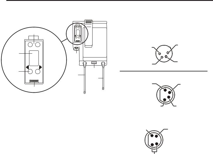
Figure 3-2
TR-80N Rear Panel/Connector/Antennas
1.[MENU] and [SET] buttons – Used to select menus and set options on the LCD.
2.LCD (Liquid Crystal Display)
3.[UP] and [DOWN] buttons – Used to select beltpack options on the LCD.
4.Programming Connector – Used to update software in unit.
(1) Microphone
Shield (-) (2) Microphone
Audio (+)
 (3) Headphone High (+)
(5) (4) Headphone Low (-)
Figure 3-3
Headset Jack Wiring
6.Battery Latch – Press down to release the battery pack. While holding the latch down, slide the battery pack about 1/8 inch back toward the latch, until it stops, then lift it out.
7.Receive Antenna – Screw type ¼-wave replaceable antenna. The color dot on the screw end of the antenna must match color dot on antenna receptacle.
8.Transmit Antenna – Screw type ¼-wave replaceable antenna. Color dot on the screw end of the antenna must match color dot on antenna receptacle.
NOTE: Microphone gain and transmit mode is set
via software menus.
3-2

TR-80N
Specifications
RF Frequency Range . . . . . . . . . . . . . . . . . . . . . . . . . . . . . . 482 - 608 MHz, 614 - 722 MHz, in 18 MHz TX and RX bands (Some frequencies only available in certain countries)
Power Requirements. . . . . . . . . . . . . . . . . . . . . . . . . . . . . . . . . . . . . . . . . . . . . . . . 6 “AA” Cells Alkaline (NiMH optional) Current Draw . . . . . . . . . . . . . . . . . . . . . . . . . . . . . . . . . . . . . . . . . . . . . . . . . . . . . . . . . . . 200 mA (Push-to-Talk, Talk On) Temperature Range . . . . . . . . . . . . . . . . . . . . . . . . . . . . . . . . . . . . . . . . . . . . . . . . . . . . . . -4° F to 130° F (-20° C to 55° C) Dimensions . . . . . . . . . . . . . . . . . . . . . . . . . . . . . . . . . . . . . . . . . 3.75”W x 5.05”H x 1.65” D (9.5 cm x 12.8 cm x 4.2 cm) Weight . . . . . . . . . . . . . . . . . . . . . . . . . . . . . . . . . . . . . . . . . . . . . . . . . . . . . . . . . . . . . . 16 oz (454g) with alkaline batteries TX Antenna. . . . . . . . . . . . . . . . . . . . . . . . . . . . . . . . . . . . . . . . . . . . . . . . . . 1/4 Wave (supplied), Screw type, Replaceable RX Antenna . . . . . . . . . . . . . . . . . . . . . . . . . . . . . . . . . . . . . . . . . . . . . . . . . 1/4 Wave (supplied), Screw type, Replaceable FCC ID:. . . . . . . . . . . . . . . . . . . . . . . . . . . . . . . . . . . . . . . . . . . . . . . . . . . . . . . . . . . . . . . . . B5DM530 (TX 608-698 MHz) Frequency Response . . . . . . . . . . . . . . . . . . . . . . . . . . . . . . . . . . . . . . . . . . . . . . . . . . . . . . . . . . . . . . . . . . . . . 200Hz-4kHz Microphone input sensitivity . . . . . . . . . . . . . . . . . . . . . . . . . . . . . . . . . . . . . . . . . . . . . . . . . . . . . . . . . . . . . . . . . . . . . 7 mV Local Headset Output . . . . . . . . . . . . . . . . . . . . . . . . . . . . . . . . . . . . . . . . . . . . . . 40 mW output into 600Ω (1% distortion)
Transmitter
Type . . . . . . . . . . . . . . . . . . . . . . . . . . . . . . . . . . . . . . . . . . . . . . . . . . . . . . . . . . . . . . . . . . . . . . . Synthesized, 720 channels Transmit Power . . . . . . . . . . . . . . . . . . . . . . . . . . . . . . . . . . . . . . . . . . . . . . . . . . . . . . . . . Selectable: Auto, 5, 50, 100 mW Modulation Type. . . . . . . . . . . . . . . . . . . . . . . . . . . . . . . . . . . . . . . . . . . . . . . . . . . . . . . . . . . . . . . . . . . . . . . . . . . . . . . . FM Deviation. . . . . . . . . . . . . . . . . . . . . . . . . . . . . . . . . . . . . . . . . . . . . . . . . . . . . . . . . . . . . . . . . . . . . . . . . . . . . . . . . . . . 4 kHz RF Frequency Stability . . . . . . . . . . . . . . . . . . . . . . . . . . . . . . . . . . . . . . . . . . . . . . . . . . . . . . . . . . . . . . . . . . . . . . . 2.5 PPM Modulation Limiter . . . . . . . . . . . . . . . . . . . . . . . . . . . . . . . . . . . . . . . . . . . . . . . . . . . . . . . . Peak-Responding Compressor Radiated Harmonics & Spurious . . . . . . . . . . . . . . . . . . . . . . . . . . . . . . . . . . . . . . . . . . . . . . . . Exceeds FCC specifications
Receiver
Type . . . . . . . . . . . . . . . . . . . . . . . . . . . . . . . . . . . . . Triple Conversion Superheterodyne, Synthesized, FM, 720 channels RF Sensitivity . . . . . . . . . . . . . . . . . . . . . . . . . . . . . . . . . . . . . . . . . . . . . . . . . . . . . . . . . . . . . . . <0.6 µV for 12 dB SINAD Squelch Threshold . . . . . . . . . . . . . . . . . . . . . . . . . . . . . . . . . . . . . . . . adjustable - 12 / 20 / 24 dB SINAD (About 1.0 μV) IF Selectivity . . . . . . . . . . . . . . . . . . . . . . . . . . . . . . . . . . . . . . . . . . . . . . . . . . . . . . . . . . . . . . . . 6 dB at 30 kHz Bandwidth Image Rejection . . . . . . . . . . . . . . . . . . . . . . . . . . . . . . . . . . . . . . . . . . . . . . . . . . . . . . . . . . . . . . . . . . . . . . . 70 dB or better Squelch Quieting. . . . . . . . . . . . . . . . . . . . . . . . . . . . . . . . . . . . . . . . . . . . . . . . . . . . . . . . . . . . . . . . . . . . . . . . . . . . . . 90 dB RF Frequency Stability . . . . . . . . . . . . . . . . . . . . . . . . . . . . . . . . . . . . . . . . . . . . . . . . . . . . . . . . . . . . . . . . . . . . . . . 2.5 PPM
3-3
3-4 Blank

Section
4
TR-82N Beltpack
Controls and Connections - Top Panel
1 |
2 |
3 |
1 |
|
|
WTA |
|
|
|
SA |
|
|
OFF |
VOL |
|
VOL |
1 |
2 |
OFF |
|
BAT/ |
||
6 |
|
PK |
6 |
TALK |
TALK |
||
|
R |
|
|
4 5 4
Figure 4-1
TR-82N Top Panel
1.On/Off and Volume Control - Turns beltpack power on and controls headset volume for intercom channels “1” and “2”. Either knob, “1” or “2”, turns the beltpack on. Both knobs must be off to turn the beltpack off. If only one knob is on, then that intercom channel, “1” or “2” is on for both transmit and receive audio.
2.Wireless Talk Around (WTA) - When pressed, the user’s audio is disconnected from the wired intercom, auxiliary input/output and the base station’s local headset. Other beltpack users, on that audio channel, can hear the user as normal. The default setting is software selectable, as to which intercom channels, “1”, “2”, “1 + 2”, or currently selected channel, is activated along with the “WTA” button. The “WTA” button activates the nearby red LED as well as the software selected intercom channels “TALK” LED if not already active.
3.Stage Announce (SA) - When pressed, the user’s audio is routed to the stage announce connector on the back of the base station. The user also loses their sidetone as an indication that stage announce is activated. The other wireless beltpacks and wired users do not hear the user’s audio. The button is non-latching and activates the nearby red LED.
4.Talk Button - Press to enable the audio path to either intercom channels “1”, “2” or “1 + 2”, from the local headset microphone. The associated “TALK” LED, #6, will turn red when enabled. A quick press and release latches the talk function, unless latching has been disabled. Holding the button for over ½ second will cause the audio path to be enabled only for as long as the button is held. If the talk function is latched on, pressing the talk button again will turn it off.
5.Low Battery/Peak (BAT/PK) Light - Light will flash once when unit is turned on if the battery is good. If the light stays on, battery is low. If the light does not flash, battery is dead. A normal microphone gain setting will cause the LED to flash for some words at normal speech levels. If the gain is too high, the LED will be red during all words at normal speech levels.
6.Talk Light - Will turn red when enabled by associated “TALK” or “WTA” button.
4-1

Controls and Connections - Rear Panel
1 |
SET |
MENU |
SET |
MENU |
5 |
2 |
|
|
|
|
|
3 |
|
|
4 |
6 |
|
SIDE VIEW
7
8
9
Figure 4-2
TR-82N Rear Panel/Connector/Antennas
1. [MENU] and [SET] buttons – Used to select menus and
set options on the LCD.
2.LCD (Liquid Crystal Display)
3.[UP] and [DOWN] buttons – Used to select beltpack options on the LCD.
4.Programming Connector - Used to update software in unit.
5.Auxiliary Input Audio Jack -1/8" (3.5mm) mono input jack. Local only to beltpack.
6.Headset Connector – Male XLR connector for Telex units, Female XLR connector for RTS units. A dynamic or electret headset microphone is automatically detected by the beltpack and a bias voltage supplied if needed. Four pin Telex/RTS units are monaural. Five pin Telex/RTS units have a software set-up to select if XLR pin 3 or 5 is
the channel 2 output and if pin 3 is ground.
Telex Units
(4) Headphone
(1) Microphone |
Low (-) |
|
Shield (-) |
||
|
||
(2) Microphone |
(3) Headphone |
|
High (+) |
||
Audio (+) |
||
|
||
(1) Microphone |
(5) Headphone |
|
Shield (-) |
Audio B |
|
(2) Microphone |
(4) Headphone |
|
Audio (+) |
Audio A |
(3) Switched Headphone Ground
(1) Microphone |
RTS Units |
|
|
Shield (-) |
(2) Microphone |
|
Audio (+) |
(4) Headphone |
(3) Headphone |
Low (-) |
High (+) |
(1) Microphone |
(2) Microphone |
Shield (-) |
|
|
Audio (+) |
|
(3) Switched |
|
Headphone Ground |
(5) Headphone |
(4) Headphone |
(Audio A) |
|
(Audio B) |
|
Figure 4-3
Headset Jack Wiring
7.Battery Latch – Press down to release the battery pack. While the latch is held down, slide the battery pack about 1/8 inch back, toward the latch, until it stops, then lift it out.
8.Receive Antenna – Screw type ¼-wave replaceable antenna. The color dot on the screw end of the antenna must match color dot on antenna receptacle.
9.Transmit Antenna – Screw type ¼-wave replaceable antenna. The color dot on the screw end of the antenna must match color dot on antenna receptacle.
NOTE: Microphone gain and transmit mode is set via
software menus.
4-2

TR-82N
Specifications
RF Frequency Range . . . . . . . . . . . . . . . . . . . . . . . . . . . . . . . 482 - 608 MHz, 614 - 722 MHz, in 18 MHz TX and RX bands (Some frequencies only available in certain countries)
Power Requirements. . . . . . . . . . . . . . . . . . . . . . . . . . . . . . . . . . . . . . . . . . . . . . . . 6 “AA” Cells Alkaline (NiMH optional) Current Draw . . . . . . . . . . . . . . . . . . . . . . . . . . . . . . . . . . . . . . . . . . . . . . . . . . . . 280 mA (Push-to-Talk, A and B Talk On) Temperature Range . . . . . . . . . . . . . . . . . . . . . . . . . . . . . . . . . . . . . . . . . . . . . . . . . . . . . . -4° F to 130° F (-20° C to 55° C) Dimensions . . . . . . . . . . . . . . . . . . . . . . . . . . . . . . . . . . . . . . . . 3.75” W x 5.35” H x 2.02” D (9.5 cm x 13.5 cm x 5.1 cm) Weight . . . . . . . . . . . . . . . . . . . . . . . . . . . . . . . . . . . . . . . . . . . . . . . . . . . . . . . . . . . . . . 21 oz (595g) with alkaline batteries TX Antenna. . . . . . . . . . . . . . . . . . . . . . . . . . . . . . . . . . . . . . . . . . . . . . . . . . 1/4 Wave (supplied), Screw type, Replaceable RX Antenna . . . . . . . . . . . . . . . . . . . . . . . . . . . . . . . . . . . . . . . . . . . . . . . . . 1/4 Wave (supplied), Screw type, Replaceable FCC ID:. . . . . . . . . . . . . . . . . . . . . . . . . . . . . . . . . . . . . . . . . . . . . . . . . . . . . . . . . . . . . . . . . B5DM531 (TX 608-698 MHz) Frequency Response . . . . . . . . . . . . . . . . . . . . . . . . . . . . . . . . . . . . . . . . . . . . . . . . . . . . . . . . . . . . . . . . . . . . . 200Hz-4kHz Microphone input sensitivity . . . . . . . . . . . . . . . . . . . . . . . . . . . . . . . . . . . . . . . . . . . . . . . . . . . . . . . . . . . . . . . . . . . . . 7 mV Local Headset Output. . . . . . . . . . . . . . . . . . . . . . . . . . . . . . . . . . . . . . . . . . . . . . 40 mW output into 600Ω (1% distortion)
Transmitter
Type . . . . . . . . . . . . . . . . . . . . . . . . . . . . . . . . . . . . . . . . . . . . . . . . . . . . . . . . . . . . . . . . . . . . . . . Synthesized, 720 channels Transmit Power . . . . . . . . . . . . . . . . . . . . . . . . . . . . . . . . . . . . . . . . . . . . . . . . . . . . . . . . . Selectable: Auto, 5, 50, 100 mW Modulation Type. . . . . . . . . . . . . . . . . . . . . . . . . . . . . . . . . . . . . . . . . . . . . . . . . . . . . . . . . . . . . . . . . . . . . . . . . . . . . . . . FM Deviation . . . . . . . . . . . . . . . . . . . . . . . . . . . . . . . . . . . . . . . . . . . . . . . . . . . . . . . . . . . . . . . . . . . . . . . . . . . . . . . . . . . 4 kHz RF Frequency Stability . . . . . . . . . . . . . . . . . . . . . . . . . . . . . . . . . . . . . . . . . . . . . . . . . . . . . . . . . . . . . . . . . . . . . . . 2.5 PPM Modulation Limiter . . . . . . . . . . . . . . . . . . . . . . . . . . . . . . . . . . . . . . . . . . . . . . . . . . . . . . . . Peak-Responding Compressor Radiated Harmonics & Spurious . . . . . . . . . . . . . . . . . . . . . . . . . . . . . . . . . . . . . . . . . . . . . . . . Exceeds FCC specifications
Receiver
Type. . . . . . . . . . . . . . . . . . . . . . . . . Two, Triple Conversion Superheterodyne Receivers, Synthesized, FM, 720 channels RF Sensitivity . . . . . . . . . . . . . . . . . . . . . . . . . . . . . . . . . . . . . . . . . . . . . . . . . . . . . . . . . . . . . . . <0.6 µV for 12 dB SINAD Squelch Threshold . . . . . . . . . . . . . . . . . . . . . . . . . . . . . . . . . . . . . . . . . . . . . . . . . . . . . . adjustable - 12 /20 /24 dB SINAD IF Selectivity . . . . . . . . . . . . . . . . . . . . . . . . . . . . . . . . . . . . . . . . . . . . . . . . . . . . . . . . . . . . . . . . 6 dB at 30 kHz Bandwidth Image Rejection . . . . . . . . . . . . . . . . . . . . . . . . . . . . . . . . . . . . . . . . . . . . . . . . . . . . . . . . . . . . . . . . . . . . . . . 70 dB or better Squelch Quieting. . . . . . . . . . . . . . . . . . . . . . . . . . . . . . . . . . . . . . . . . . . . . . . . . . . . . . . . . . . . . . . . . . . . . . . . . . . . . . 90 dB RF Frequency Stability . . . . . . . . . . . . . . . . . . . . . . . . . . . . . . . . . . . . . . . . . . . . . . . . . . . . . . . . . . . . . . . . . . . . . . . 2.5 PPM
4-3
4-4 Blank

Section
5
Initial Equipment Set-Up
Unpacking
Unpack your RadioCom™ System. Below are the items that |
Contact the shipper or your dealer immediately if anything is |
should come with your base station and each belt pack. |
damaged or missing. |
BTR-80N
Quantity |
Description |
|
|
1 |
BTR-80N Base Station |
|
|
1 |
Operating Instructions |
|
|
1 |
Power Cord |
|
|
2 |
Antennas (one Transmit and one Receive) |
|
|
1 |
Warranty Card |
|
|
1 |
2 terminal plug (for SA Relay) |
|
|
4 |
Rubber feet |
|
|
TR-80N, TR-82N
Quantity |
Description |
|
|
1 |
TR-80N or TR-82N with Antennas |
|
|
1 |
Battery pack |
1 |
Quick Start Card |
1 |
Warranty Card |
|
|
1 |
Belt Clip |
|
|
1 |
LCD Cover |
|
|
5-1

Antenna Connection
The base station is supplied with two (2) antennas. One 1/2-wave antenna for Transmit and one 1/2-wave for Receive. The antennas have TNC male connectors.
TR-80N
The frequency range of the antennas should match the receiver and transmitter of the base station. Match the color code on the antenna with the color code on the base station.
BTR-80N |
CHANNEL |
|
INPUTS |
SELECT |
ON/O.M. |
|
1 |
TALK |
|
2 |
|
Attach the transmit 1/2-wave antenna to the antenna input re- ceptacle labeled “Transmit” on the right side of the rear panel. The antenna should be vertically aligned.
ANTENNAS SHOULD BE VERTICAL
Figure 5-3
Vertically Polarized Antennas
Figure 5-1
Attaching Transmit 1/2-Wave Antenna
Attach the receive 1/2-wave antenna to the antenna input re- ceptacle labeled “Receive” on the left side of the rear panel. The antenna should be vertically aligned.
Distance between Antennas
The distance between the base station’s receive and transmit antennas is not adjustable when the antennas are connected di- rectly on the back of the unit.
The antennas can be remotely mounted for a better signal path. A Telex coax assembly with remote antennas may be re- quired. See "Accessory" section for ordering information.
NOTE: If your base station is to be located in a shielded rack mount enclosure or other poor RF location, you must remotely mount the 1/2-wave antennas with coax assemblies. See "Ac- cessories and Replacement Parts" section for remote mounting hardware.
Antenna Placement
Proper antenna placement probably has the most effect on your TELEX Wireless Intercom System’s overall perfor- mance. The following suggestions will result in optimum per- formance.
Proper placement of the beltpack can be critical. The antennas should be in the open. Bending the antennas up and placing the beltpack in a pocket, etc., will reduce system distance.
It is suggested that the unit be worn on the belt with both an- tennas vertical for best operating range and performance.
A
TR-80N
Figure 5-2
Attaching Receive 1/2-Wave Antenna
Antenna Polarization
The Telex Wireless Intercom System is “Vertically Polarized”.
This means both the transmitting and receiving antennas
Figure 5-4
should operate in the vertical position.
Proper Dressing of the Antennas
5-2
Keep the distance between the base station and the beltpacks as short as possible. The greater the distance, the weaker the signal. Make sure the “signal paths” between the base station and beltpacks are unobstructed. You should be able to visibly locate the base station antennas at all times for best perfor- mance.
Attempting to operate the wireless intercom system through or around walls, ceilings, metal objects, etc. will reduce system range and performance.
TR-80N
TR-80N
70 FEET
100 FEET
|
MENU |
BTR-80N |
UP |
|
|
|
|
|
|
|
CHANNEL |
|
|
|
PORTABLE STATION CONNECT |
|
|
|
|
|
|||||
|
|
|
|
|
|
|
INPUTS |
|
SELECT |
ON/O.M. |
||
|
ClearScan |
|
1 |
2 |
3 |
4 |
|
|
|
|
1 |
TALK |
|
|
|
|
|
|
1 |
2 |
1 |
2 |
AUX |
2 |
|
POWER |
SET |
COPY |
DOWN |
|
|
4 WIRE |
|
|
2 WIRE |
|
|
|
|
|
|
|
|
|
|
|
|
||||
Figure 5-5
Distance Between base station and beltpack
TR-80N
BTR-80N
TR-80N
Figure 5-7
Operating System Near Obstructions
DO NOT - mount the base station 1/2-wave antennas on, or next to metal, such as beams, walls with metal studs, equip- ment racks, etc. This also applies to the antennas when assem- bled directly to the Base Station. This will “detune” the antennas which can result in noise or loss of RF signal at the Base Station, see Figure 5-8.
BTR-80N |
CHANNEL |
|
INPUTS |
SELECT |
ON/O.M. |
|
1 |
TALK |
|
2 |
|
TR-80N
Figure 5-6
Keeping Site Clear to Antenna
5-3

2.Placing the BTR on top of a shelf or equipment rack unobstructed without remoting the antennas is OK.
1.Placing BTRs in a shelf or equipment rack and using remote antennas is OK.
3.Placing BTRs in a shelf or equipment rack with the antennas mounted on the back of the BTR or the side of the rack is BAD.
BTR-80N
BTR-80N
BTR-80N
BTR-80N
BTR-80N
#1 |
#2 |
#3 |
Figure 5-8
Antenna Placement
Improving Reception and Increasing
Range
Keeping the distance from the base station and beltpack as short, and unobstructed as possible will produce the most reli- able performance.
The base station is supplied with two antennas. This should provide satisfactory system performance in most applications. System range can be enhanced by remotely mounting the 1/2-wave antennas. The ½ wave antennas are ground plane in- dependent, so a ground plane is not required for good perfor- mance.
5-4
5-5 Blank

Section
6
BTR-80N Operation
BTR-80N Operation
This Section will discuss the operation and features of the BTR-80N base station. The section will open with the base operation and quick system setup of a BTR-80N system. It will then discuss basic interfacing and setup of a base station. Finally it will end with the connection of multiple base stations and discussion of the links between them.
Basic Operational Description
The BTR-80N narrow band wireless intercom system offers the most comprehensive, user friendly and versatile set of features available in wireless intercom systems anywhere in the world.
The base station can accommodate up to 4 full duplex TR-80N or TR-82N beltpacks. A base may be used with an unlimited number of beltpacks in push-to-TX (half duplex) operation. In push-to-TX mode the unit provides a "First-On-Latch-Out" feature. This feature allows only one beltpack transmitter active at a time when multiple users are on a single base receive channel.
The base station, via the beltpacks or it's local headset, allows communication with other wireless or wired users. The 2-wire and 4-wire intercoms may even be used at the same time. The wired audio interfaces to the base are:
•2-Wire (Telex, RTS, Clear-Com) - 2 intercom channels
•4-Wire - 2 audio channels
•Auxiliary (both input and output)
•SA (Stage Announce) (output)
•WTA (Wireless Talk Around). 2 channels of a private 2-wire intercom just among TR-80N and TR-82N
beltpacks.
for the user to enter frequencies of their own via 12 user de-
fined groups.
System Quick Start
The following is a list to quickly get a base station and beltpacks operating.
1.Unpack the base and connect the power cord and antennas.
2.Connect base to audio interfaces. For example; 2-wire, 4-wire, SA, Auxiliary local headset.
3.Press and hold [MENU] as powering-up the base station. Release button when base station displays "...FACTORY SETUP...".
4.Press [MENU] as powering-up the beltpacks(s)
5.Use the [UP] and [DOWN] arrow button to change the channel to an unoccupied receive channel on the base station. Then press [SET] twice to set channel and group.
6.The base should now display the audio channel of the beltpack and a battery symbol will appear shortly.
7.Plug a headset into each beltpack. Adjust the software menu for microphone gain so the overmodulation light flashes only on some of the words at normal speech levels.
•Local base station headset
The base also has a relay closure available that is activated when the SA is pressed at any beltpack. There are 4 easily accessible portable connect buttons on the front panel. The buttons may be used to turn off the audio from any of the four base receivers while at the same time killing the talk/transmitter at the associated beltpack.
The base station comes with 36 engineering selected, intermodulation-avoiding groups of channels, plus the ability
6-1

RECEIVE |
|
2-WIRE |
|
2-WIRE |
|
|
|
|
|
|
|
|
TRANSMIT |
|||
|
INTERCOM |
|
INTERCOM |
|
|
|
|
|
|
|
|
|||||
JACK |
|
|
|
|
|
|
|
|
|
|
|
JACK |
||||
|
PORT |
|
PORT |
|
|
|
|
|
|
|
|
|
||||
|
|
|
|
|
|
|
|
|
|
|
|
|
|
|
||
|
BTR-80N BASE STATION |
|
|
|
|
AUXILIARY |
STAGE |
|
|
|
|
|
|
|
||
|
|
|
|
|
|
|
|
|
|
|
|
|||||
|
|
|
LINK |
|
|
|
|
AUDIO |
|
|
|
|
1/2 |
|
||
|
|
|
|
|
|
|
ANNOUNCE |
|
100-240 VAC 50-60 Hz |
T |
||||||
|
|
|
|
|
|
|
|
|
12-15 VDC |
|
|
|
|
|
|
R |
|
|
|
IN |
O |
4 WIRE |
|
4 WIRE |
|
3.5 A |
MADE IN U.S.A. |
|
|
A |
|||
|
RELAY |
PROGRAM |
P |
P |
|
|
|
|
N |
|||||||
|
|
|
|
|
|
|
|
|
|
|
|
|
|
S |
||
CONTACT |
|
T |
|
T |
|
|
|
|
|
|
|
|
|
M |
||
RECEIVE |
|
H |
|
H |
|
|
|
|
|
|
|
|
|
I |
||
|
|
|
|
R |
|
R |
|
|
|
|
|
|
|
|
|
|
|
|
|
OUT |
U |
|
U |
|
|
|
|
|
|
|
|
|
T |
|
|
|
|
|
|
|
|
|
|
|
|
|
|
2 |
||
|
|
|
|
|
|
|
INPUT |
OUTPUT |
OUTPUT |
|
Telex Communications, Inc. |
|
|
|
||
Figure 6-1 |
TWO CHANNELS OF TELEX OR |
BTR-80N Rear View |
CLEAR-COM INTERCOM |
|
(from wired power supply) |
Transmit and Receive Antennas
The TNC transmit jack and receiver jack are both labeled on the rear of the unit. The base station will come with two ½ wave antennas. Always match the color dot on the rear panel of the base station with the colored band on the antenna.
BTR-80N |
BASE STATION |
INTERCOM 1 |
INTERCOM 2 |
|
STAGE |
|
|
|
|
|
|
|
LINK |
|
|
|
1/2 |
|
|||
|
|
|
2 WIRE |
2 WIRE |
|
ANNOUNCE |
12-15 VDC |
100-240 VAC 50-60 Hz |
RT |
|
|
|
|
|
|
|
|
3.5 A |
|
|
A |
RELAY |
PROGRAM |
IN |
4 WIRE |
4 WIRE |
|
|
MADE IN U.S.A. |
|
|
NS |
CONTACT |
|
|
|
|
|
|
|
|
|
M |
RECEIVE |
|
|
|
|
|
|
|
|
|
I |
|
|
OUT |
|
|
|
|
|
|
2 |
T |
|
|
|
|
INPUT |
OUTPUT |
OUTPUT |
|
Telex Communications, Inc. |
|
|
2-Wire Intercom Ports
The base station has the ability to interface to two, 2-wire ex- ternal audio intercom systems. These XLR jacks are desig- nated intercom 1 and 2 on the rear panel.
BTR-80N |
BASE STATION |
INTERCOM 1 |
INTERCOM 2 |
|
STAGE |
|
|
|
|
|
|
|
LINK |
|
|
|
1/2 |
|
|||
|
|
|
2 WIRE |
2 WIRE |
|
ANNOUNCE |
12-15 VDC |
100-240 VAC 50-60 Hz |
RT |
|
|
|
IN |
|
|
|
|
3.5 A |
|
|
A |
RELAY |
PROGRAM |
4 WIRE |
4 WIRE |
|
|
MADE IN U.S.A. |
|
|
NS |
|
CONTACT |
|
|
|
|
|
|
|
|
|
M |
RECEIVE |
|
|
|
|
|
|
|
|
|
I |
|
|
OUT |
|
|
|
|
|
|
2 |
T |
|
|
|
|
|
|
|
|
|
||
|
|
|
|
INPUT |
OUTPUT |
OUTPUT |
|
Telex Communications, Inc. |
|
|
TO OTHER 2-WIRE EQUIPMENT
They accept Telex, RTS and Clear-Com types of intercom sys- tems. The pinouts of these standard types of intercom are shown in Figure 6-2.
|
COMMON |
1 |
AUDIO 1 PLUS POWER |
2 |
|
RTS |
AUDIO 2 |
3 |
|
|
COMMON |
1 |
AUDIO (-) PLUS POWER |
2 |
|
Telex/ |
|
AudioCom 3 |
AUDIO (+) PLUS POWER |
|
COMMON |
1 |
POWER |
2 |
|
Clear-Com |
|
3 |
AUDIO |
Figure 6-2
Pin Outs of RTS, Telex and Clear-Com Intercoms
The base station does not require "wet" intercom lines for op- eration. Wet intercom lines are those with D.C. voltages on them for powering 2-wire devices. The base will loop thru wet intercom lines with currents up to 2 Amps.
Warning! Do not loop thru more than 2 Amps of current.
Damage to the base station may result.
Figure 6-3
Loop-thru of Two Base Stations connected with
Telex/Audiocom or Clear-Com Intercoms
Since RTS-TW carries both channels of audio on one cable, the four intercom XLR connectors are connected in parallel when RTS is selected. Thus any one of the four intercom XLRs may be used for RTS input. As shown in Figure 6-4, looping thru of the audio may also be accomplished via any of the rear panel XLRs when in RTS mode. For a description of how to set up the 2-wire ports refer to "Intercom Settings" in this section.
TWO CHANNELS OF RTS INTERCOM (from wired power supply)
BTR-80N |
BASE STATION |
|
AUXILIARY |
STAGE |
|
|
|
|
|
|
LINK |
|
AUDIO |
100-240 VAC 50-60 Hz |
1/2 |
T |
|
|
|
|
|
|
ANNOUNCE |
|||
|
|
|
|
|
12-15 VDC |
|
|
R |
|
|
|
|
|
3.5 A |
MADE IN U.S.A. |
|
A |
RELAY |
PROGRAM |
IN |
4 WIRE |
|
|
|
NS |
|
CONTACT |
|
|
|
|
|
|
|
M |
RECEIVE |
|
|
|
|
|
|
|
I |
|
|
OUT |
U |
|
|
|
2 |
T |
|
|
|
INPUT |
OUTPUT |
OUTPUT |
Telex Communications, Inc. |
|
|
BTR-80N |
BASE STATION |
INTERCOM 1 |
AUXILIARY |
STAGE |
|
|
|
|
|
|
LINK |
2 WIRE |
AUDIO |
100-240 VAC 50-60 Hz |
1/2 |
T |
|
|
|
|
|
ANNOUNCE |
||||
|
|
|
L |
|
12-15 VDC |
|
|
R |
|
|
IN |
OO |
|
3.5 A |
|
|
A |
RELAY |
PROGRAM |
|
4 WIRE |
|
MADE IN U.S.A. |
|
|
NS |
CONTACT |
|
|
|
|
|
|
|
M |
RECEIVE |
|
|
|
|
|
|
|
I |
|
|
OUT |
|
|
|
|
2 |
T |
|
|
|
|
|
|
|
||
|
|
|
INPUT |
OUTPUT |
OUTPUT |
Telex Communications, Inc. |
|
|
TO OTHER 2-WIRE EQUIPMENT
Figure 6-4
Loop-thru of Two Base Stations Connected
with RTS Intercoms
The 2-wire intercom may be used at the same time as the 4-wire intercom.
6-2

AUXILIARY
|
|
|
|
|
|
4-WIRE |
INPUT |
|
|
|
|
|
|
|
|
|
|
|
|
|
|
|
INTERCOM PORTS |
|
|
|
|
|
|
|
|
||
|
|
|
|
|
|
|
AUXILIARY |
|
|
|
|
|
|
|
|
|
|
|
|
|
|
|
|
|
|
|
|
|
|
|
|
|
|
|
|
|
|
|
|
|
|
OUTPUT |
|
|
|
|
|
|
|
|
|
BTR-80N BASE STATION |
INTERCOM 1 |
|
|
|
AUXILIARY |
STAGE |
|
|
|
|
|
|
|
||
|
|
|
|
|
|
|
|
|
|
|
||||||
|
|
|
LINK |
|
|
|
AUDIO |
|
|
|
|
1/2 |
|
|||
|
|
|
2 WIRE |
|
|
|
ANNOUNCE |
|
100-240 VAC 50-60 Hz |
T |
||||||
|
|
|
|
L |
|
|
|
|
12-15 VDC |
|
|
|
|
|
R |
|
|
|
|
IN |
O |
|
|
|
|
3.5 A |
|
|
|
|
|
A |
|
|
|
|
O |
4 W |
RE |
|
|
MADE IN U.S.A. |
|
|
|
|
|
N |
||
|
RELAY |
PROGRAM |
P |
|
|
|
|
|
|
|
||||||
|
|
|
|
|
|
|
|
|
|
|
|
|
|
S |
||
CONTACT |
|
T |
|
|
|
|
|
|
|
|
|
|
|
M |
||
RECEIVE |
|
H |
|
|
|
|
|
|
|
|
|
|
|
I |
||
|
|
|
|
R |
|
|
|
|
|
|
|
|
|
|
|
|
|
|
|
OUT |
U |
|
U |
|
|
|
|
|
|
|
2 |
T |
|
|
|
|
|
|
|
|
INPUT |
OUTPUT |
OUTPUT |
Telex Communications, Inc. |
|
|
|
|||
Figure 6-5
BTR-80N Rear View
4-Wire Intercom Ports
The BTR-80N can connect to two 4-wire audio intercom sys- tems. These 6-pin modular jacks (RJ-11) are designated "4 wire" under intercom 1 and 2 titles on the rear panel. (See Fig- ure 6-5). The jacks' pinout is shown in Figure 6-6.
PIN |
6 5 4 |
3 2 1 |
NC = NOT CONNECTED
NC |
NC |
AUDIO IN - |
AUDIO IN + |
AUDIO OUT - |
AUDIO OUT + |
Figure 6-6
Pinout of the 4-Wire Jack
The 4-wire intercom may be used at the same time as the 2-wire intercom.
Auxiliary Input/Output
The auxiliary input jack is a combination jack. It will accept either a 3-pin XLR or 1/4" (6.3mm) plug, the expected input is a balanced line level input. The XLR plug and 1/4 plug are wired in parallel as shown in Figure 6-7.
|
+ AUDIO |
|
- AUDIO |
|
GROUND |
1 |
SLEEVE |
3 |
RING |
TIP |
GROUND
- AUDIO
+ AUDIO
1
3
Figure 6-8
Pinout of the Auxiliary Output Jack
The auxiliary input/output can be set to local, global or off. (See the Aux Settings menu in the base). The output level is settable in software.
•Local Aux Input = The input audio is only heard at the base station's local headset and beltpacks.
•Local Aux Output = The output audio is only from the local headset and beltpacks.
•Global Aux Input = The input audio is heard at the base station's local headset, beltpacks and placed on the
2-wire/ 4-wire intercom.
•Global Aux Output = The output audio is from the base station's local headset, beltpacks and 2-wire/4-wire
intercom.
•Off = The auxiliary input and output is off.
Figure 6-7
Auxiliary Input XLR and 6.3 mm Jack Pinouts
Auxiliary output is a 3-pin XLR jack. It produces a line level balanced output. Please refer to Figure 6-8 for the pin out.
Figure 6-9
6-3
 Loading...