


APPLICATIONS |
CHG. NO. |
|
|
|
REVISIONS |
|
|
|
|||||||||
|
|
|
LTR |
|
|
DESCRIPTION |
DATE |
APPD |
|||||||||
|
|
|
|
|
|||||||||||||
|
|
|
A |
|
|
RELEASE |
|
|
|
||||||||
|
|
|
B |
Manual changed to Rev. B |
|
JA |
|||||||||||
|
|
10-67-02 C |
|
|
Correction of typo |
|
JA |
||||||||||
|
|
11-47-02 D |
Manual changed to Rev. D |
02-17-03 |
JA |
||||||||||||
|
|
04-80-03 |
E |
Change TR-825 XLR pinouts, add E88/G9 Antennas |
04-29-03 |
JA |
|||||||||||
|
|
12-54-03 |
F |
|
|
Add CE information |
01-05-04 |
JA |
|||||||||
|
|
03-49-04 |
G |
Eliminate Customer Service & Limited Warranty in T.O.C. |
04-22-04 |
DO |
|||||||||||
|
|
Eliminate Customer Service & Limited Warranty |
|||||||||||||||
NEXT ASSY. |
USED ON |
70-000340 |
H |
Update manual for European requirements |
03-16-05 |
JRC |
|||||||||||
|
|
|
|
|
|
|
|
|
|
|
|
|
|
|
|
||
|
|
|
|
|
|
|
|
|
|
|
|
|
|
|
|
|
|
|
|
|
|
|
|
|
8 1/2” |
|
|
|
|
|
|
|
|
||
|
|
|
|
|
|
|
|
|
|
|
|
|
|
|
|
|
803257 |
|
|
|
|
|
|
|
|
|
|
|
|
|
|
|
|
|
|
|
|
|
|
|
|
|
|
|
|
|
|
|
|
|
|
|
- |
|
|
|
|
|
|
|
|
|
|
|
|
|
|
|
|
|
1 |
|
|
|
|
|
|
|
|
|
|
|
|
|
|
|
|
|
|
|
|
|
|
|
|
|
|
|
|
|
|
11” |
|
|
|
||
|
|
|
|
|
|
|
|
|
|
|
|
|
|
|
|||
|
|
|
|
|
|
|
|
|
|
|
|
|
|
|
|
|
|
 0891
0891
4. VENDOR: COMMERCIAL PRINTER
3. TELEX TO SUPPLY ARTWORK
2.MATERIAL: 60# OFFSET WITH 65LB LAURENTINE COVER OR EQUIVALENT, WHITE WITH BLACK LETTERING.
1. MANUAL FOLDED AND STAPLED.
NOTES:
TOLERANCES |
|
|
03-16-05 |
|
|
|
|
|
DATE |
|
|
|
TELEX |
||||
UNLESS OTHERWISE |
|
|
NH |
|
TELEX COMMUNICATIONS, INC. |
|||
SPECIFIED |
DR BY |
|
|
|||||
|
|
Lincoln, Nebraska U.S.A. |
||||||
FRACTION |
CHK BY |
|
JTN |
TITLE |
|
|
|
|
|
|
|
|
|
|
|||
DECIMAL |
APPD. |
|
JRC 03-16-05 |
BTR-800, TR-800, TR-825 |
||||
|
INSTRUCTION MANUAL |
|||||||
|
|
|||||||
ANGLE |
|
|
|
|||||
PROD. |
|
|
|
|
|
|
|
|
|
|
|
|
|
|
|
|
|
|
|
|
|
|
|
|
|
|
This drawing, written description or specifi- |
UNLESS OTHERWISE |
SIZE |
CODE IDENT |
DWG. NO. |
||||
cation represents a proprietary product of |
S |
57010 |
803257-1 |
|||||
Telex, Lincoln, NE, and shall not be |
SPECIFIED DIMENSIONS |
|||||||
released, disclosed, used nor duplicated |
ARE IN INCHES. |
SCALE: |
NONE |
|
|
SHEET: 1 of 1 |
||
|
|
|||||||
without the written permission of TELEX |
|
|
|
|
||||
|
|
|
|
|
|
|
|
|
Telex
Operating Instructions
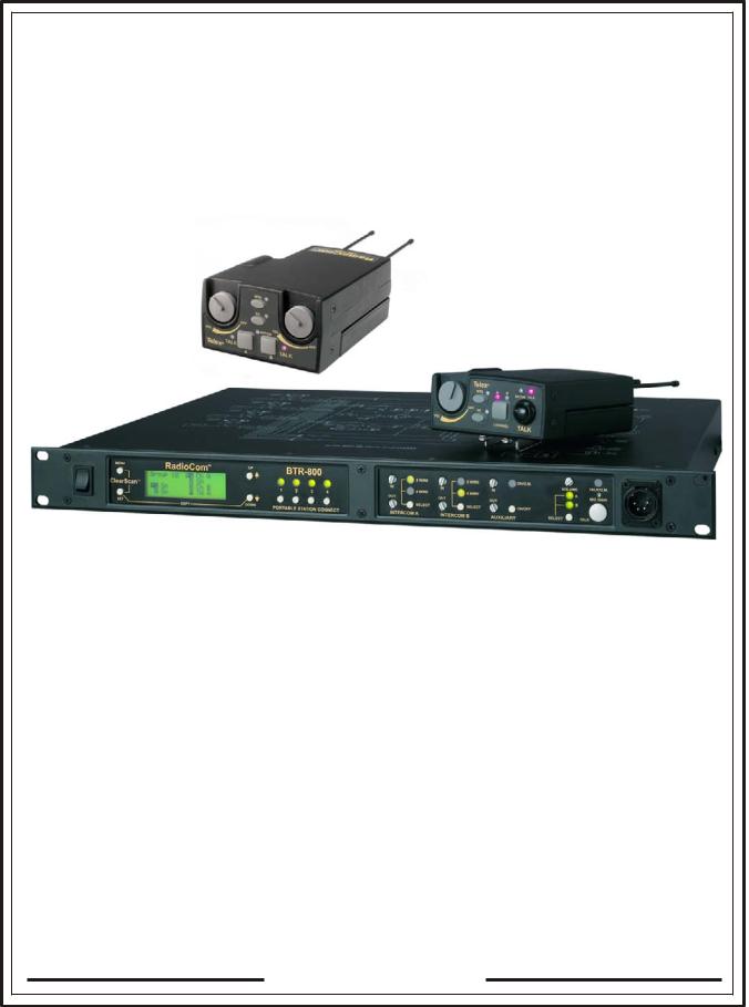
RadioCom™
BTR-800, TR-800, TR-825
Professional
Wireless
Intercom System
 0891
0891

Thank you for choosing RadioComTM
Telex Communications would like to take this opportunity to thank you for choosing the RadioCom™ BTR-800 Professional Wireless Intercom System. Many of the features in this product are the result of years of development work with many of the features developed from customer feedback. We hope that your experience with this product is a pleasant one and hope to provide you with a continuing line of RadioCom™ products well into the future. In order to get the most out of your new wireless intercom system, please take a few moments to look through this booklet before using the product for the first time.
-Telex Communications, Inc.
Table of Contents
Introduction . . . . . . . . . . . . . . . . . . . . . . . . . . . . . . . . . . . . . . . . . . . . . . . . . . . . . . . . . . . . . . . . . . . . . . . . . . 1-1
General Description . . . . . . . . . . . . . . . . . . . . . . . . . . . . . . . . . . . . . . . . . . . . . . . . . . . . . . . . . . . . . . . . . . . . . . . . . . 1-1
System Features . . . . . . . . . . . . . . . . . . . . . . . . . . . . . . . . . . . . . . . . . . . . . . . . . . . . . . . . . . . . . . . . . . . . . . . . . . . . . 1-1
BTR-800 Block Diagram. . . . . . . . . . . . . . . . . . . . . . . . . . . . . . . . . . . . . . . . . . . . . . . . . . . . . . . . . . . . . . . . . . . . . . 1-2
BTR-800 Base Station . . . . . . . . . . . . . . . . . . . . . . . . . . . . . . . . . . . . . . . . . . . . . . . . . . . . . . . . . . . . . . . . . . 2-1
Controls and Connections - Front Panel . . . . . . . . . . . . . . . . . . . . . . . . . . . . . . . . . . . . . . . . . . . . . . . . . . . . . . . . . . 2-1
Controls and Connections - Rear Panel . . . . . . . . . . . . . . . . . . . . . . . . . . . . . . . . . . . . . . . . . . . . . . . . . . . . . . . . . . . 2-2
BTR-800 Specifications. . . . . . . . . . . . . . . . . . . . . . . . . . . . . . . . . . . . . . . . . . . . . . . . . . . . . . . . . . . . . . . . . . . . . . . 2-3
TR-800 Beltpack. . . . . . . . . . . . . . . . . . . . . . . . . . . . . . . . . . . . . . . . . . . . . . . . . . . . . . . . . . . . . . . . . . . . . . . 3-1
Controls and Connections - Top Panel. . . . . . . . . . . . . . . . . . . . . . . . . . . . . . . . . . . . . . . . . . . . . . . . . . . . . . . . . . . . 3-1
Controls and Connections - Rear Panel . . . . . . . . . . . . . . . . . . . . . . . . . . . . . . . . . . . . . . . . . . . . . . . . . . . . . . . . . . . 3-2
TR-800 Specifications . . . . . . . . . . . . . . . . . . . . . . . . . . . . . . . . . . . . . . . . . . . . . . . . . . . . . . . . . . . . . . . . . . . . . . . . 3-3
TR-825 Beltpack . . . . . . . . . . . . . . . . . . . . . . . . . . . . . . . . . . . . . . . . . . . . . . . . . . . . . . . . . . . . . . . . . . . . . . 4-1
Controls and Connections - Top Panel. . . . . . . . . . . . . . . . . . . . . . . . . . . . . . . . . . . . . . . . . . . . . . . . . . . . . . . . . . . . 4-1
Controls and Connections - Rear Panel . . . . . . . . . . . . . . . . . . . . . . . . . . . . . . . . . . . . . . . . . . . . . . . . . . . . . . . . . . . 4-2
TR-825 Specifications . . . . . . . . . . . . . . . . . . . . . . . . . . . . . . . . . . . . . . . . . . . . . . . . . . . . . . . . . . . . . . . . . . . . . . . . 4-3
Initial Equipment Set-Up . . . . . . . . . . . . . . . . . . . . . . . . . . . . . . . . . . . . . . . . . . . . . . . . . . . . . . . . . . . . . . . 5-1
Unpacking . . . . . . . . . . . . . . . . . . . . . . . . . . . . . . . . . . . . . . . . . . . . . . . . . . . . . . . . . . . . . . . . . . . . . . . . . . . . . . . . . 5-1
Antenna Connections. . . . . . . . . . . . . . . . . . . . . . . . . . . . . . . . . . . . . . . . . . . . . . . . . . . . . . . . . . . . . . . . . . . . . . . . . 5-2
Antenna Polarization . . . . . . . . . . . . . . . . . . . . . . . . . . . . . . . . . . . . . . . . . . . . . . . . . . . . . . . . . . . . . . . . . . . . . . . . . 5-2
Distance Between Antennas . . . . . . . . . . . . . . . . . . . . . . . . . . . . . . . . . . . . . . . . . . . . . . . . . . . . . . . . . . . . . . . . . . . 5-2
Antenna Placement . . . . . . . . . . . . . . . . . . . . . . . . . . . . . . . . . . . . . . . . . . . . . . . . . . . . . . . . . . . . . . . . . . . . . . . . . . 5-2
Improving Reception/Increasing Range . . . . . . . . . . . . . . . . . . . . . . . . . . . . . . . . . . . . . . . . . . . . . . . . . . . . . . . . . . 5-4
Base Station Set-Up . . . . . . . . . . . . . . . . . . . . . . . . . . . . . . . . . . . . . . . . . . . . . . . . . . . . . . . . . . . . . . . . . . . . . . . . . 5-5
Location . . . . . . . . . . . . . . . . . . . . . . . . . . . . . . . . . . . . . . . . . . . . . . . . . . . . . . . . . . . . . . . . . . . . . . . . . . . . . . . 5-5
Power Connection. . . . . . . . . . . . . . . . . . . . . . . . . . . . . . . . . . . . . . . . . . . . . . . . . . . . . . . . . . . . . . . . . . . . . . . . 5-5
Transmit Switches. . . . . . . . . . . . . . . . . . . . . . . . . . . . . . . . . . . . . . . . . . . . . . . . . . . . . . . . . . . . . . . . . . . . . . . . 5-5
Internal Transmit Switches . . . . . . . . . . . . . . . . . . . . . . . . . . . . . . . . . . . . . . . . . . . . . . . . . . . . . . . . . . . . . . . . . 5-6
Intercom Switch . . . . . . . . . . . . . . . . . . . . . . . . . . . . . . . . . . . . . . . . . . . . . . . . . . . . . . . . . . . . . . . . . . . . . . . . . 5-6
Intercom Interface. . . . . . . . . . . . . . . . . . . . . . . . . . . . . . . . . . . . . . . . . . . . . . . . . . . . . . . . . . . . . . . . . . . . . . . . 5-6
Dual Listen Functionality . . . . . . . . . . . . . . . . . . . . . . . . . . . . . . . . . . . . . . . . . . . . . . . . . . . . . . . . . . . . . . . . . . 5-8
Auxiliary Input/Output . . . . . . . . . . . . . . . . . . . . . . . . . . . . . . . . . . . . . . . . . . . . . . . . . . . . . . . . . . . . . . . . . . . . 5-9
Internal Auxiliary Input Routing Switch . . . . . . . . . . . . . . . . . . . . . . . . . . . . . . . . . . . . . . . . . . . . . . . . . . . . . . 5-9
Stage Announce /Relay Contacts . . . . . . . . . . . . . . . . . . . . . . . . . . . . . . . . . . . . . . . . . . . . . . . . . . . . . . . . . . . 5-10
Base Station Link . . . . . . . . . . . . . . . . . . . . . . . . . . . . . . . . . . . . . . . . . . . . . . . . . . . . . . . . . . . . . . . . . . . . . . . 5-11
Beltpack Set-Up . . . . . . . . . . . . . . . . . . . . . . . . . . . . . . . . . . . . . . . . . . . . . . . . . . . . . . . . . . . . . . . . . . . . . . . . . . . 5-12
Battery Installation . . . . . . . . . . . . . . . . . . . . . . . . . . . . . . . . . . . . . . . . . . . . . . . . . . . . . . . . . . . . . . . . . . . . . . 5-12
Antenna Connection . . . . . . . . . . . . . . . . . . . . . . . . . . . . . . . . . . . . . . . . . . . . . . . . . . . . . . . . . . . . . . . . . . . . . 5-13
Transmit Mode . . . . . . . . . . . . . . . . . . . . . . . . . . . . . . . . . . . . . . . . . . . . . . . . . . . . . . . . . . . . . . . . . . . . . . . . . 5-13
Headset Connection . . . . . . . . . . . . . . . . . . . . . . . . . . . . . . . . . . . . . . . . . . . . . . . . . . . . . . . . . . . . . . . . . . . . . 5-13
Pre-Walk-Thru Checklist . . . . . . . . . . . . . . . . . . . . . . . . . . . . . . . . . . . . . . . . . . . . . . . . . . . . . . . . . . . . . . . 6-1
System Operation. . . . . . . . . . . . . . . . . . . . . . . . . . . . . . . . . . . . . . . . . . . . . . . . . . . . . . . . . . . . . . . . . . . . . . 7-1 Frequency Plan Overview . . . . . . . . . . . . . . . . . . . . . . . . . . . . . . . . . . . . . . . . . . . . . . . . . . . . . . . . . . . . . . . . . . . . . 7-1 Factory-Defined Group . . . . . . . . . . . . . . . . . . . . . . . . . . . . . . . . . . . . . . . . . . . . . . . . . . . . . . . . . . . . . . . . . . . . . . . 7-1 User-Programmable Groups . . . . . . . . . . . . . . . . . . . . . . . . . . . . . . . . . . . . . . . . . . . . . . . . . . . . . . . . . . . . . . . . . . . 7-1 System Quick Start . . . . . . . . . . . . . . . . . . . . . . . . . . . . . . . . . . . . . . . . . . . . . . . . . . . . . . . . . . . . . . . . . . . . . . . . . . 7-1 Base Station Operation . . . . . . . . . . . . . . . . . . . . . . . . . . . . . . . . . . . . . . . . . . . . . . . . . . . . . . . . . . . . . . . . . . . . . . 7-2
Power . . . . . . . . . . . . . . . . . . . . . . . . . . . . . . . . . . . . . . . . . . . . . . . . . . . . . . . . . . . . . . . . . . . . . . . . . . . . . . . . . 7-2 Local Headset . . . . . . . . . . . . . . . . . . . . . . . . . . . . . . . . . . . . . . . . . . . . . . . . . . . . . . . . . . . . . . . . . . . . . . . . . . . 7-2 Portable Station Connect . . . . . . . . . . . . . . . . . . . . . . . . . . . . . . . . . . . . . . . . . . . . . . . . . . . . . . . . . . . . . . . . . . 7-2 Intercom A and B . . . . . . . . . . . . . . . . . . . . . . . . . . . . . . . . . . . . . . . . . . . . . . . . . . . . . . . . . . . . . . . . . . . . . . . . 7-2 Auxiliary. . . . . . . . . . . . . . . . . . . . . . . . . . . . . . . . . . . . . . . . . . . . . . . . . . . . . . . . . . . . . . . . . . . . . . . . . . . . . . . 7-2 Display Contrast . . . . . . . . . . . . . . . . . . . . . . . . . . . . . . . . . . . . . . . . . . . . . . . . . . . . . . . . . . . . . . . . . . . . . . . . . 7-3 BTR-800 Menu Structure. . . . . . . . . . . . . . . . . . . . . . . . . . . . . . . . . . . . . . . . . . . . . . . . . . . . . . . . . . . . . . . . . 7-4
Main Screen Flowchart . . . . . . . . . . . . . . . . . . . . . . . . . . . . . . . . . . . . . . . . . . . . . . . . . . . . . . . . . . . . . . . . . 7-4 Power-Up Screen . . . . . . . . . . . . . . . . . . . . . . . . . . . . . . . . . . . . . . . . . . . . . . . . . . . . . . . . . . . . . . . . . . . . . . 7-5 Operating Screen . . . . . . . . . . . . . . . . . . . . . . . . . . . . . . . . . . . . . . . . . . . . . . . . . . . . . . . . . . . . . . . . . . . . . . 7-5 Beltpack Activity Code Definitions . . . . . . . . . . . . . . . . . . . . . . . . . . . . . . . . . . . . . . . . . . . . . . . . . . . . . . . . 7-5 Group/Channel Select . . . . . . . . . . . . . . . . . . . . . . . . . . . . . . . . . . . . . . . . . . . . . . . . . . . . . . . . . . . . . . . . . . 7-6 Group/Frequency Select. . . . . . . . . . . . . . . . . . . . . . . . . . . . . . . . . . . . . . . . . . . . . . . . . . . . . . . . . . . . . . . . . 7-7 Frequency Edit . . . . . . . . . . . . . . . . . . . . . . . . . . . . . . . . . . . . . . . . . . . . . . . . . . . . . . . . . . . . . . . . . . . . . . . 7-8 Clear Scan . . . . . . . . . . . . . . . . . . . . . . . . . . . . . . . . . . . . . . . . . . . . . . . . . . . . . . . . . . . . . . . . . . . . . . . . . . . 7-9 Special Key Sequences . . . . . . . . . . . . . . . . . . . . . . . . . . . . . . . . . . . . . . . . . . . . . . . . . . . . . . . . . . . . . . . . 7-10
Lockout . . . . . . . . . . . . . . . . . . . . . . . . . . . . . . . . . . . . . . . . . . . . . . . . . . . . . . . . . . . . . . . . . . . . . . . . . 7-10 Copy . . . . . . . . . . . . . . . . . . . . . . . . . . . . . . . . . . . . . . . . . . . . . . . . . . . . . . . . . . . . . . . . . . . . . . . . . . . 7-10 1st Use Default . . . . . . . . . . . . . . . . . . . . . . . . . . . . . . . . . . . . . . . . . . . . . . . . . . . . . . . . . . . . . . . . . . . 7-10 Factory Default . . . . . . . . . . . . . . . . . . . . . . . . . . . . . . . . . . . . . . . . . . . . . . . . . . . . . . . . . . . . . . . . . . . 7-10
-i-
Table of Contents (continued)
TR-800 Beltpack Operation . . . . . . . . . . . . . . . . . . . . . . . . . . . . . . . . . . . . . . . . . . . . . . . . . . . . . . . . . . . . . . . . . 7-11 Power/Local Headset Volume. . . . . . . . . . . . . . . . . . . . . . . . . . . . . . . . . . . . . . . . . . . . . . . . . . . . . . . . . . . . . . 7-11 Battery Check . . . . . . . . . . . . . . . . . . . . . . . . . . . . . . . . . . . . . . . . . . . . . . . . . . . . . . . . . . . . . . . . . . . . . . . . . . 7-11 Talk Button . . . . . . . . . . . . . . . . . . . . . . . . . . . . . . . . . . . . . . . . . . . . . . . . . . . . . . . . . . . . . . . . . . . . . . . . . . . . 7-11 Microphone Gain . . . . . . . . . . . . . . . . . . . . . . . . . . . . . . . . . . . . . . . . . . . . . . . . . . . . . . . . . . . . . . . . . . . . . . . 7-11 Channel Select Button . . . . . . . . . . . . . . . . . . . . . . . . . . . . . . . . . . . . . . . . . . . . . . . . . . . . . . . . . . . . . . . . . . . 7-11 Stage Announce (SA) . . . . . . . . . . . . . . . . . . . . . . . . . . . . . . . . . . . . . . . . . . . . . . . . . . . . . . . . . . . . . . . . . . . . 7-11 Wireless Talk Around (WTA). . . . . . . . . . . . . . . . . . . . . . . . . . . . . . . . . . . . . . . . . . . . . . . . . . . . . . . . . . . . . . 7-11 TR-800 Beltpack Menu Structure . . . . . . . . . . . . . . . . . . . . . . . . . . . . . . . . . . . . . . . . . . . . . . . . . . . . . . . . . 7-12
Power-Up Screens . . . . . . . . . . . . . . . . . . . . . . . . . . . . . . . . . . . . . . . . . . . . . . . . . . . . . . . . . . . . . . . . . . . . 7-13 Group/Channel Screen . . . . . . . . . . . . . . . . . . . . . . . . . . . . . . . . . . . . . . . . . . . . . . . . . . . . . . . . . . . . . . . . . 7-14 Transmit Screen . . . . . . . . . . . . . . . . . . . . . . . . . . . . . . . . . . . . . . . . . . . . . . . . . . . . . . . . . . . . . . . . . . . . . . 7-15 Receive 1 Screen . . . . . . . . . . . . . . . . . . . . . . . . . . . . . . . . . . . . . . . . . . . . . . . . . . . . . . . . . . . . . . . . . . . . . 7-16 Receive 2 Screen . . . . . . . . . . . . . . . . . . . . . . . . . . . . . . . . . . . . . . . . . . . . . . . . . . . . . . . . . . . . . . . . . . . . . 7-17 ClearScan™ . . . . . . . . . . . . . . . . . . . . . . . . . . . . . . . . . . . . . . . . . . . . . . . . . . . . . . . . . . . . . . . . . . . . . . . . . 7-18 Feature Enable/Disable Menus . . . . . . . . . . . . . . . . . . . . . . . . . . . . . . . . . . . . . . . . . . . . . . . . . . . . . . . . . . 7-19 Stage Announce Enable/Disable . . . . . . . . . . . . . . . . . . . . . . . . . . . . . . . . . . . . . . . . . . . . . . . . . . . . . . . . . 7-19 Wireless Talk Around Enable/Disable . . . . . . . . . . . . . . . . . . . . . . . . . . . . . . . . . . . . . . . . . . . . . . . . . . . . . 7-19 Audio Channel A or B Enable/Disable . . . . . . . . . . . . . . . . . . . . . . . . . . . . . . . . . . . . . . . . . . . . . . . . . . . . 7-20 Talk Button Latch on/Latch off . . . . . . . . . . . . . . . . . . . . . . . . . . . . . . . . . . . . . . . . . . . . . . . . . . . . . . . . . . 7-20 Special Key Sequences . . . . . . . . . . . . . . . . . . . . . . . . . . . . . . . . . . . . . . . . . . . . . . . . . . . . . . . . . . . . . . . . 7-21
Lockout . . . . . . . . . . . . . . . . . . . . . . . . . . . . . . . . . . . . . . . . . . . . . . . . . . . . . . . . . . . . . . . . . . . . . . . . . 7-21 1st Use Default . . . . . . . . . . . . . . . . . . . . . . . . . . . . . . . . . . . . . . . . . . . . . . . . . . . . . . . . . . . . . . . . . . . 7-21 Factory Default . . . . . . . . . . . . . . . . . . . . . . . . . . . . . . . . . . . . . . . . . . . . . . . . . . . . . . . . . . . . . . . . . . . 7-21 TR-825 Beltpack Menu Structure . . . . . . . . . . . . . . . . . . . . . . . . . . . . . . . . . . . . . . . . . . . . . . . . . . . . . . . . . 7-22 Power-Up Screens . . . . . . . . . . . . . . . . . . . . . . . . . . . . . . . . . . . . . . . . . . . . . . . . . . . . . . . . . . . . . . . . . . . . 7-23 Group/Channel Screen . . . . . . . . . . . . . . . . . . . . . . . . . . . . . . . . . . . . . . . . . . . . . . . . . . . . . . . . . . . . . . . . . 7-24 Transmit Screen . . . . . . . . . . . . . . . . . . . . . . . . . . . . . . . . . . . . . . . . . . . . . . . . . . . . . . . . . . . . . . . . . . . . . . 7-25 Receive 1 Screen . . . . . . . . . . . . . . . . . . . . . . . . . . . . . . . . . . . . . . . . . . . . . . . . . . . . . . . . . . . . . . . . . . . . . 7-26 Receive 2 Screen . . . . . . . . . . . . . . . . . . . . . . . . . . . . . . . . . . . . . . . . . . . . . . . . . . . . . . . . . . . . . . . . . . . . . 7-27 Audio Output . . . . . . . . . . . . . . . . . . . . . . . . . . . . . . . . . . . . . . . . . . . . . . . . . . . . . . . . . . . . . . . . . . . . . . . . 7-28 ClearScan™ . . . . . . . . . . . . . . . . . . . . . . . . . . . . . . . . . . . . . . . . . . . . . . . . . . . . . . . . . . . . . . . . . . . . . . . . . 7-29 Feature Enable/Disable Menus . . . . . . . . . . . . . . . . . . . . . . . . . . . . . . . . . . . . . . . . . . . . . . . . . . . . . . . . . . 7-30 Stage Announce Enable/Disable . . . . . . . . . . . . . . . . . . . . . . . . . . . . . . . . . . . . . . . . . . . . . . . . . . . . . . . . . 7-30 Wireless Talk Around . . . . . . . . . . . . . . . . . . . . . . . . . . . . . . . . . . . . . . . . . . . . . . . . . . . . . . . . . . . . . . . . . 7-31 Audio Channel A Options . . . . . . . . . . . . . . . . . . . . . . . . . . . . . . . . . . . . . . . . . . . . . . . . . . . . . . . . . . . . . . 7-32 Audio Channel B Options . . . . . . . . . . . . . . . . . . . . . . . . . . . . . . . . . . . . . . . . . . . . . . . . . . . . . . . . . . . . . . 7-33 Special Key Sequences . . . . . . . . . . . . . . . . . . . . . . . . . . . . . . . . . . . . . . . . . . . . . . . . . . . . . . . . . . . . . . . . 7-34 Lockout . . . . . . . . . . . . . . . . . . . . . . . . . . . . . . . . . . . . . . . . . . . . . . . . . . . . . . . . . . . . . . . . . . . . . . . . . 7-34 1st Use Default . . . . . . . . . . . . . . . . . . . . . . . . . . . . . . . . . . . . . . . . . . . . . . . . . . . . . . . . . . . . . . . . . . . 7-34 Factory Default . . . . . . . . . . . . . . . . . . . . . . . . . . . . . . . . . . . . . . . . . . . . . . . . . . . . . . . . . . . . . . . . . . . 7-34
System Walk-Thru . . . . . . . . . . . . . . . . . . . . . . . . . . . . . . . . . . . . . . . . . . . . . . . . . . . . . . . . . . . . . . . . . . . . . 8-1
Trouble Shooting . . . . . . . . . . . . . . . . . . . . . . . . . . . . . . . . . . . . . . . . . . . . . . . . . . . . . . . . . . . . . . . . . . . . . . 9-1
Tech Tips . . . . . . . . . . . . . . . . . . . . . . . . . . . . . . . . . . . . . . . . . . . . . . . . . . . . . . . . . . . . . . . . . . . . . . . . . . . . 10-1
Frequency Interaction . . . . . . . . . . . . . . . . . . . . . . . . . . . . . . . . . . . . . . . . . . . . . . . . . . . . . . . . . . . . . . . . . . . . . . . 10-1
Microphone Gain Adjustment . . . . . . . . . . . . . . . . . . . . . . . . . . . . . . . . . . . . . . . . . . . . . . . . . . . . . . . . . . . . . . . . . 10-1
Battery Information . . . . . . . . . . . . . . . . . . . . . . . . . . . . . . . . . . . . . . . . . . . . . . . . . . . . . . . . . . . . . . . . . . . 11-1
Intercom System Specifications . . . . . . . . . . . . . . . . . . . . . . . . . . . . . . . . . . . . . . . . . . . . . . . . . . . . . . . . . 12-1
Accessories and Replacement Parts . . . . . . . . . . . . . . . . . . . . . . . . . . . . . . . . . . . . . . . . . . . . . . . . . . . . . . 13-1
Software License. . . . . . . . . . . . . . . . . . . . . . . . . . . . . . . . . . . . . . . . . . . . . . . . . . . . . . . . . . . . . . . . . . . . . . 14-1
Certification Information . . . . . . . . . . . . . . . . . . . . . . . . . . . . . . . . . . . . . . . . . . . . . . . . . . . . . . . . . . . . . . 15-1
Declaration of Conformity . . . . . . . . . . . . . . . . . . . . . . . . . . . . . . . . . . . . . . . . . . . . . . . . . . . . . . . . . . . . . 15-2
-ii-

Section
1
Introduction
General Description
The Telex RadioCom™ BTR-800 UHF Synthesized Wireless inter com systems offer the ultimate in reliab le, high-performance, high-fidelity full-duplex communications.
The BTR-800 system includes the BTR-800 frequency agile base station, working with up to four TR-800 or TR-825 frequency agile beltpacks. The BTR-800 base station provides full-duplex communications with the beltpacks.
The BTR system incorporates two audio channel operation, permitting the beltpack operator to choose between two separate audio channels of communications, with the base station tracking the beltpack selection. This allows the user the flexibility to create a party-line and a private line within the same beltpack.
The BTR-800 system is perfectly suited for stand-alone operation and also can interface with Audiocom® (Telex), RTS® TW, Clear-Com®, as well as RTS Matrix systems and other 4-wire communications systems. In addition to the external intercom systems interfaces listed above, the system provides connections for auxiliary balanced audio input and output, as well as wireless talk-around (WTA) and stage announce (SA) features.
The RadioCom™ BTR series has been designed for reliable, efficient operation. Operating in the 470 to 740 MHz range, the units operate reliably at line-of-sight distances of 1,000 feet. With available antenna systems, from Telex, the effective operating range can be extended. The high-efficiency beltpacks provide up to 12 hours of uninterrupted operation using standard alkaline batteries.
System Features
•Frequency-agile base station and beltpacks. No external computer/device required to select frequencies.
•Backlit base-station LCD allows the user to easily monitor the beltpack’s status as well as change base-station fre-
quencies.
•ClearScan™ function on base station and beltpack to automatically find the best channels on which to operate.
•Full-duplex (simultaneous talk and listen) operation.
•Compatible with Audiocom® (Telex), RTS TW, Matrix, Clear-Com® , and other wired intercom types.
•Two channels of intercom audio.
•WTA (Wireless Talk Around) beltpack control. This feature allows beltpacks to talk to each other, but their audio
is lifted from any wired system connected to the base station.
•SA (Stage Announce) beltpack control. Allows the user to direct their audio to a jack on the back of the base for P.A.
systems or other external audio systems.
•Relay contact closure on the base when the SA button is pressed.
•TR-825 features two audio channel binaural operation in either stereo or mono mode.
•Beltpack units contained in a weather and shock resistant die cast magnesium case.
•Convenient IEC power connector on the base station so the unit can plug directly to outlets. No in-line or wall
plug power supply.
•Base station comes with rack ears for easy rack mounting.
RTS® and Audiocom® are registered trademarks of Telex Communications, Inc. Clear-Com® is a registered trademark of Clear-Com Intercom Systems, Inc.
1-1

2-1
PORTABLE
STATION 1
CONNECT
LOGIC
RECEIVE 1
PORTABLE
STATION 2 
CONNECT
LOGIC
RECEIVE 2
PORTABLE
STATION 3
CONNECT
LOGIC
RECEIVE 3
PORTABLE
STATION 4 
CONNECT
LOGIC
RECEIVE 4
WTA A
1 OF 5
SELECT
CHANNEL A |
|
|
A |
B |
TALK |
CHANNEL |
|
TALK |
SELECT |
|
|
|
|
|
1 OF 5 |
|
|
SELECT |
LOGIC |
|
HEADSET |
VOLUME |
|
1 |
4 |
|
2 3
XLR
MIC
GAIN
1 OF 5  SELECT
CHANNEL B
AUXILIARY
AUDIO
IN
INPUT
XLR
FEMALE ON/O.M.
ON/OFF
1 OF 5
SELECT 
WTA B
SA
BTR-800 Block Diagram
 TRANSMIT 1
INTERCOM A
OUT  2 WIRE
INTERCOM A
IN
R J11
STYLE
4 WIRE
2 WIRE
INTERCOM B
IN
RJ11
STYLE
4 WIRE
INTERCOM B
OUT
OUT
 TRANSMIT 2
LOGIC
LOGIC |
SELECT |
4 |
2 |
W |
W |
I |
I |
R |
R |
E |
E |
INTERCOM A |
|
|
MALE FEMALE |
|
L |
4 WIRE 2 WIRE |
|
INTERCOM B
4 WIRE 2 WIRE
XLR
MALE FEMALE
LOGIC  SELECT
AUXILIARY
AUDIO
OUTPUT
XLR
MALE
XLR
MALE
STAGE
ANNOUNCE
OUTPUT
RELAY
CONTACT
Section
2
BTR-800 Base Station
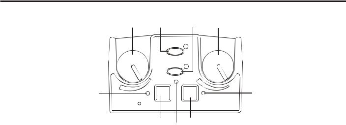
Controls and Connections - Front Panel
|
1 |
2 |
3 |
4 |
5 |
6 |
7 |
8 |
9 |
|
11 |
|
|
10 |
12 |
||||||||||
|
|
|
|
|
|
|
|
|
|
|||
|
|
MENU |
RadioComä |
UP |
BTR-800 |
2 WIRE |
2 WIRE |
|
ON/O.M. |
VOLUME |
TALK/O.M. |
|
|
|
|
|
|
|
IN |
IN |
IN |
|
|
||
|
|
ClearScanTM |
|
|
|
|
A |
|
|
|||
|
|
|
|
1 2 3 4 |
4 WIRE |
4 WIRE |
|
|
MIC GAIN |
|
||
|
|
|
|
|
OUT |
OUT |
OUT |
|
B |
|
|
|
|
|
|
|
|
|
|
|
|
|
|
||
|
|
|
|
|
|
SELECT |
SELECT |
|
ON/OFF |
|
|
|
|
|
SET |
COPY |
DOWN |
PORTABLE STATION CONNECT |
INTERCOM A |
INTERCOM B |
AUXILIARY |
SELECT |
TALK |
|
|
|
|
|
|
|
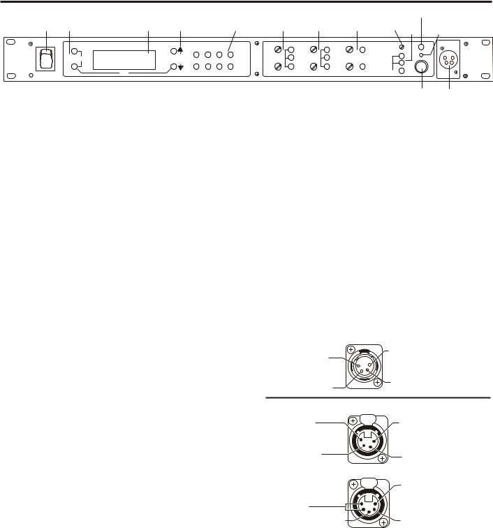
Figure 1 |
|
|
|
|
13 |
14 |
|
|
|
|
|
|
BTR-800 - Front Panel |
|
|
|
|
|
|
|
1. |
Power switch. |
|
|
|
11. Talk/Overmod Light – LED is green when talk button |
|||||||
|
|
|
|
|
|
#13 is active. A normal mic gain setting will cause the |
||||||
2. [Menu] and [Set] buttons – Used to select menus and set |
LED to flash red on the loudest speech levels. If the gain |
|||||||||||
|
options on the LCD. |
|
|
|
is too high, the LED will be red at normal speech volumes. |
|||||||
3. |
Backlit Graphics LCD (Liquid Crystal Display). |
12. Microphone Gain – Adjusts the headset’s microphone |
||||||||||
|
|
|
|
|
|
gain. Adjusts so that the overmod light #11 flashes from |
||||||
4. [Up] and [Down] buttons – Used to select base station |
green to red on loudest speech. |
|
|
|
||||||||
|
options on the LCD. |
|
|
|
|
|
|
|
|
|
|
|
5.Portable Station Connect – Buttons used to enable or disable the respective receiver’s audio. GREEN LED = Audio enabled, LED OFF = Audio disabled.
6.Intercom A Controls - Wired intercom A interface controls. Audio input and output level controls. 2-wire or 4-wire select button with green LED indicator lights. Selected LED will change to RED if the input levels are too high.
7.Intercom B Controls - Wired intercom B interface controls. Audio input and output level controls. 2-wire or 4-wire select button with green LED indicator lights. Selected LED will change to RED if the input levels are too high.
8.Auxiliary Controls - Wired auxiliary interface controls. Audio input and output level controls. GREEN LED = Aux. input enabled. LED will change to RED if the input levels are too high.
9.Headset Volume – Controls the volume to the headset connected to #14.
10.Headset Intercom Select – Controls the intercom to which the local headset is connected. Each press of the button changes the connection; channel A, channel B, both.
13.Talk Button – Press to enable the audio path from the local headset. LED #11 will turn green when enabled. A quick press and release latches button on. If the talk function is latched on, pressing the talk button again will turn it off.
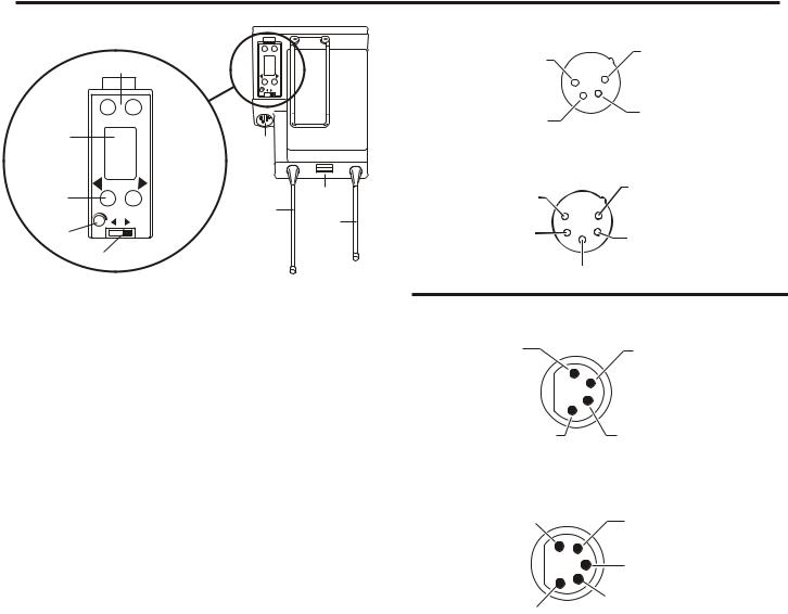
14.Local Headset Connector – Male XLR connector for Telex units, Female XLR connector for RTS units. A dynamic or electret headset microphone is automatically detected.
Telex Units
(1) Microphone |
|
(4) Headphone |
Shield (-) |
|
Low (-) |
(2) Microphone |
|
(3) Headphone |
Audio (+) |
|
High (+) |
(4) Headphone |
|
RTS Units |
|
(1) Microphone |
|
Low (-) |
PUSH |
|
|
|
|
|
|
Shield (-) |
(3) Headphone |
|
|
High (+) |
|
(2) Microphone |
|
|
Audio (+) |
|
PUSH |
(1) Microphone |
|
|
|
(5) (4) Headphone |
|
Shield (-) |
Low (-) |
|
|
(3) Headphone |
|
(2) Microphone |
High (+) |
|
Audio (+) |
Figure 2
Local Headset Wiring
2-1
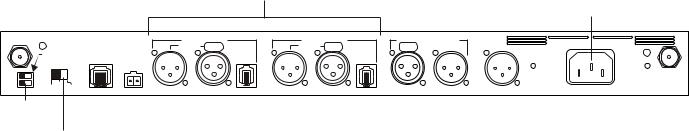
Controls and Connections - Rear Panel
1 |
|
|
|
|
|
|
|
|
|
|
|
12 |
RECEIVE |
BTR-800 |
|
INTERCOM A |
INTERCOM B |
AUXILIARY AUDIO |
|
|
|
||||
FCC ID: B5DM514 |
|
STAGE ANNOUNCE |
100-240 VAC 50-60 Hz |
|
||||||||
|
|
CANADA 1321231218A |
|
2 WIRE |
PUSH |
2 WIRE PUSH |
PUSH |
|
|
|
||
|
TRANSMIT |
BASE STATION |
|
L |
|
L |
|
|
|
|
|
|
|
|
O |
4 WIRE |
O |
4 WIRE |
|
|
|
|
|||
|
POWER |
LINK |
RELAY |
O |
O |
|
|
|
|
|||
|
|
|
|
P |
|
P |
|
|
|
|
|
|
|
|
|
|
CONTACT |
|
|
|
|
|
|
||
|
|
I/C |
|
T |
|
T |
|
|
Telex |
|
|
|
HIGH |
NORM |
|
|
|
|
|
|
TRANSMIT |
||||
|
|
R |
|
R |
|
|
Telex Communications, Inc. |
|
||||
|
|
H |
|
H |
|
|
|
|
||||
ON |
OFF |
RTS |
|
|
U |
|
U |
|
|
|
|
|
|
TELEX CLEARCOM |
|
|
|
|
|
INPUT |
OUTPUT |
OUTPUT |
POWER |
MADE IN USA |
|
|
|
|
|
|
|
|
|
|||||
2 |
3 |
4 |
5 |
6 |
|
7 |
8 |
|
9 |
10 |
11 |
|
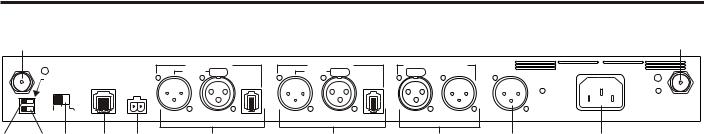
Figure 3
BTR-800 - Rear Panel
1.Receive Antenna - Female “TNC” Connector. Color band on antenna must match color dot on base station.
2.Transmit Power Switch – HIGH = Transmitters at full power. NORMAL = Transmitters 10dB below full power.
3.Transmit ON/OFF Switch – Turns the transmitters on or off.
4.I/C Select Switch – Set to the appropriate 2-wire intercom type being interfaced to the unit. Set to either Telex, RTS or Clear-Com®.
5.Base Station Link Jack – When two base stations are connected through this jack, it allows wireless talk around (WTA) from the beltpacks to be routed from the system with it’s transmitters off to the system with it’s transmitters on.
6.Relay Contact – A dry contact closure which is activated when a beltpack user presses the stage announce (SA) button. Normally Open (NO). One amp at 24V maximum.
7.Intercom A – Interface to wired intercom system A.
2-Wire – Male and female 3-pin XLR connectors wired in parallel. The connectors are switched to the appropriate intercom configuration via the I/C Select Switch.
4-Wire – An RJ-11 type jack compatible with “Matrix” type intercom systems.
8. Intercom B – Interface to wired intercom system B. 2-Wire – Male and female 3-pin XLR connectors wired in parallel. The connectors are switched to the appropriate intercom configuration via the I/C Select Switch.
4-Wire – An RJ-11 type jack compatible with “Matrix” type intercom systems.
9.Auxiliary Input/Output – One 3-pin female XLR input connector and one 3-pin male XLR output connector.
10.Stage Announce Output – Passes the audio from any of the base station’s beltpacks that have selected stage announce (SA).
11.Power – IEC receptacle. Accepts 100 – 240 VAC, 50 – 60 Hz.
12.Transmit Antenna - Female “TNC” Connector. Color band on antenna must match color dot on base station.
2-2

BTR-800
Specifications
Overall
RF Frequency Range . . . . . . . . . . . . . . . . . . . . . . 470 - 608 MHz, 614 - 740 MHz in 18 MHz TX and RX bands Power Requirements . . . . . . . . . . . . . . . . . . . . . . . . . . . . . . . . . . . . . . . 100-240 VAC, 50-60 Hz, IEC receptacle Temperature Range . . . . . . . . . . . . . . . . . . . . . . . . . . . . . . . . . . . . . . . . . . . . . . -4° F to 130° F (-20° C to 55° C) Dimensions . . . . . . . . . . . . . . . . . . . . . . . . . . . . . 19.00” W x 1.72” H x 14.00” D (48.3 cm x 4.4 cm x 35.6 cm) Weight . . . . . . . . . . . . . . . . . . . . . . . . . . . . . . . . . . . . . . . . . . . . . . . . . . . . . . . . . . . . . . . . . . . 7 lbs 2 oz (3.24 kg) TX Antenna . . . . . . . . . . . . . . . . . . . . . . . . . . . . . . . . . . . . . . . . . . . . 1/2 Wave (supplied), TNC Male Connector RX Antenna . . . . . . . . . . . . . . . . . . . . . . . . . . . . . . . . . . . . . . . . . . . . 1/2 Wave (supplied), TNC Male Connector FCC ID: . . . . . . . . . . . . . . . . . . . . . . . . . . . . . . . . . . . . . . . . . . . . . . . . . . . . . . . . . . . . . . . . . . . . . . . . . B5DM514 Frequency Response. . . . . . . . . . . . . . . . . . . . . . . . . . . . . . . . . . . . . . . . . . . . . . . . . . . . . . . . . . . . . . 300Hz-8kHz Four Wire Input . . . . . . . . . . . . . . . . . . . . . . . . . . . . . . . . . . . . . . . . . . . . . . . . Level Adjustable (2 Vrms typical) Four Wire Output . . . . . . . . . . . . . . . . . . . . . . . . . . . . . . . . . . . . . . . . . . . . . . . Level Adjustable (2 Vrms typical) Telex Intercom. . . . . . . . . . . . . . . . . . . . Input/Output Level Adjustable (1 Vrms typical), Line impedance 300W
RTS Intercom . . . . . . . . . . . . . . . . . Input/Output Level Adjustable (0.775 Vrms typical), Line Impedance 200W
Clear-Com® Intercom . . . . . . . . . . . . . Input/Output Level Adjustable (1 Vrms typical), Line Impedance 200W
Auxiliary Input . . . . . . . . . . . . . . . . . . . . . . . . . . . . . . . . . . . . . . . . . . . . . . . . . . . . . . Adjustable (2 Vrms typical) Auxiliary Output . . . . . . . . . . . . . . . . . . . . . . . . . . . . . . . . . . . . . . . . . . . . Adjustable (2 Vrms typical into 600W) Stage Announce Output . . . . . . . . . . . . . . . . Internally Adjustable (2 Vrms typical at rated deviation into 600W) Stage Announce Relay . . . . . . . . . . . . . . . . . . . . . . . . . . . . . . . . . . . . . . . Dry contact, rated at 1 Amp, 24V Max Microphone input sensitivity . . . . . . . . . . . . . . . . . . . . . . . . . . . . . . . . . . . . . . . . . . . . . . . . . . . . . . . . . . . . . 9mV Local Headset Output . . . . . . . . . . . . . . . . . . . . . . . . . . . . . . . . . . . . . . 40mW output into 600W (1% Distortion)
Transmitter
Type . . . . . . . . . . . . . . . . . . . . . . . . . . . . . . . . . . . . . . . . . . . . . Two Synthesized Transmitters, 712 channels each Transmit Power (each transmitter). . . . . . . . . . . . . . . . . . . . . . . . . . . . . . 100mW Max. (High), 10 mW (Normal) Modulation Type . . . . . . . . . . . . . . . . . . . . . . . . . . . . . . . . . . . . . . . . . . . . . . . . . . . . . . . . . . . . . . . . . . . . . . . . FM Deviation . . . . . . . . . . . . . . . . . . . . . . . . . . . . . . . . . . . . . . . . . . . . . . . . . . . . . . . . . . . . . 40 kHz (35 kHz Europe) RF Frequency Stability . . . . . . . . . . . . . . . . . . . . . . . . . . . . . . . . . . . . . . . . . . . . . . . . . . . . . . . . . . . . . . . . 0.005% Modulation Limiter . . . . . . . . . . . . . . . . . . . . . . . . . . . . . . . . . . . . . . . . . . . . . . . . Peak-Responding Compressor Radiated Harmonics & Spurious . . . . . . . . . . . . . . . . . . . . . . . . . . . . . . . . . . . . . . . . Exceeds FCC specifications
Receiver
Type. . . . . . . . . . Dual Conversion Superheterodyne, four Independent Synthesized IFs, FM, 712 channels each RF Sensitivity. . . . . . . . . . . . . . . . . . . . . . . . . . . . . . . . . . . . . . . . . . . . . . . . . . . . . . . . <0.8 µV for 12 dB SINAD Squelch Threshold . . . . . . . . . . . . . . . . . . . . . . . . . . . . . . . . . . . . . . . . . . . . . . . . . . . . . . . . . . . . . . 20 dB SINAD IF Selectivity. . . . . . . . . . . . . . . . . . . . . . . . . . . . . . . . . . . . . . . . . . . . . . . . . . . . . . . . . . . . . . . . . 3 dB at 230 kHz Image Rejection . . . . . . . . . . . . . . . . . . . . . . . . . . . . . . . . . . . . . . . . . . . . . . . . . . . . . . . . . . . . . . . 70 dB or better Squelch Quieting. . . . . . . . . . . . . . . . . . . . . . . . . . . . . . . . . . . . . . . . . . . . . . . . . . . . . . . . . . . . . . . . . . . . . . 90 dB RF Frequency Stability . . . . . . . . . . . . . . . . . . . . . . . . . . . . . . . . . . . . . . . . . . . . . . . . . . . . . . . . . . . . . . . . 0.005% Distortion . . . . . . . . . . . . . . . . . . . . . . . . . . . . . . . . . . . . . . . . . . . . . . . . . . . . . . . . . . . . . . . <1% at full deviation
2-3
2-4 Blank

Section
3
TR-800 Beltpack
Controls and Connections - Top Panel
1 2 4 5 6
|
TelexR |
A |
B |
|
|
WTA |
BAT/OM TALK |
||
|
|
|
||
|
OFF |
|
|
7 |
|
SA |
|
|
|
VOL |
|
CHANNEL |
TALK |
|
|
|
|
||
3
Figure 4
TR-800 Top Panel
1.On/Off & Volume Control – Turns the beltpack power on and controls headset volume.
2.Wireless Talk Around (WTA) – When pressed, the user’s audio is disconnected from the wired intercom, auxiliary input/output and the base station’s local headset. Other beltpack users, on that audio channel, can hear the user as normal. The button activates the nearby red LED as well as the “TALK” LED, #6, when pressed.
3.Stage Announce (SA) –When pressed, the user’s audio is routed to the stage announce connector on the back of the base station. The user also loses their sidetone as an indication that stage announce is activated. The other wireless beltpacks and wired users do not hear the user’s audio. The button is non-latching and activates the nearby red LED as well as the “TALK” LED, #6, when pressed.
4.Audio Channel Select Button – Allows user to select either audio channel A or B.
5.Bat/Overmod Light (BAT/OM) – Light will flash once when unit is turned on if the battery is good. If the light stays on, battery is low. If the light does not flash, battery is dead. A normal microphone gain setting will cause the LED to flash at the beginning of most words at normal speech levels. If the gain is too high, the LED will be red during the complete word at normal speech levels.
6.Talk Light – LED is on when the talk button, SA or WTA is active.
7.Talk button – Press to enable the audio path from the local headset microphone. The “TALK” LED, #6, will turn red when enabled. A quick press and release latches the talk function, unless latching has been disabled. Holding the button for over ½ a second will cause the audio path to be enabled only for as long as the button is held. If the talk function is latched on, pressing the talk button again will turn it off.
3-1
Controls and Connections - Rear Panel
SET |
MENU |
|
1 |
|
|
|
|
MIC PT |
PT |
|
|
TX |
TALK |
|
SET |
MENU |
|
2 |
|
6 |
|
|
|
|
|
3 |
MIC PT PT |
|
7 |
|
TX TALK |
8 |
|
4 |
|
|
9 |
|
|
|
|
|
5 |
|
|
6.Headset Connector – Male XLR connector for Telex units, Female XLR connector for RTS units. A dynamic or electret headset microphone is automatically detected by the beltpack and a bias voltage supplied if needed.
Telex Units
(4) Headphone
(1) Microphone
Low (-)
Shield (-)
(3) Headphone
(2) Microphone
High (+)
Audio (+)
RTS Units
(1) Microphone
Shield (-) (2) Microphone
Audio (+)
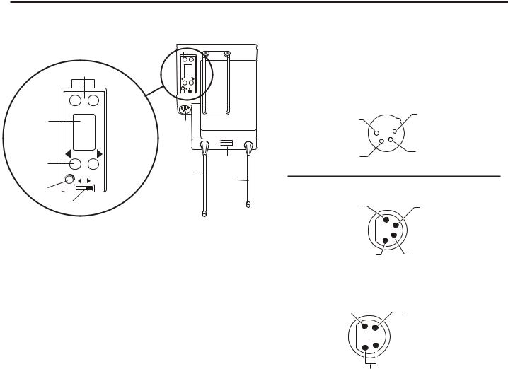
Figure 5
TR-800 Rear Panel/Connector/Antennas
1.[MENU] and [SET] buttons – Used to select menus and set options on the LCD.
2.LCD (Liquid Crystal Display)
3.[UP] and [DOWN] buttons – Used to select beltpack options on the LCD.
4.Microphone Gain – Adjusts the headset’s microphone gain. Adjust so that the BAT/OM LED will flash at the beginning of most words at normal speech levels
5.Push-to-Talk/Push-to-Transmit Switch –
Push-to-Talk (PT TALK) – The transmitter is always on. No audio sent unless the talk switch, WTA or SA button pressed. Recommended position.
Push-to-Transmit (PT TX) - The transmitter and audio path are off except when the talk switch, WTA or SA button is pressed.
(4) Headphone |
(3) Headphone |
Low (-) |
High (+) |
(1) Microphone
Shield (-) (2) Microphone
Audio (+)
 (3) Headphone High (+)
(5) (4) Headphone Low (-)
Figure 6
Headset Jack Wiring
7.Battery Latch – Press down to enable the battery pack to be released. While the latch is held down, slide the battery pack about 1/8 inch back, toward the latch, until it stops. Then lift out.
8.Receive Antenna – Screw type ¼-wave replaceable antenna. The color dot on the screw end of the antenna must match color dot on antenna receptacle.
9.Transmit Antenna – Screw type ¼-wave replaceable antenna. Color dot on the screw end of the antenna must match color dot on antenna receptacle.
3-2

TR-800
Specifications
RF Frequency Range . . . . . . . . . . . . . . . . . . . . . . 470 - 608 MHz, 614 - 740 MHz in 18 MHz TX and RX bands Power Requirements. . . . . . . . . . . . . . . . . . . . . . . . . . . . . . . . . . . . . . . . 6 “AA” Cells Alkaline (NiMH optional) Current Draw . . . . . . . . . . . . . . . . . . . . . . . . . . . . . . . . . . . . . . . . . . . . . . . . . . . 140 mA (Push-to-Talk, Talk On) Temperature Range . . . . . . . . . . . . . . . . . . . . . . . . . . . . . . . . . . . . . . . . . . . . . . -4° F to 130° F (-20° C to 55° C) Dimensions . . . . . . . . . . . . . . . . . . . . . . . . . . . . . . . . . 3.75”W x 5.05”H x 1.65” D (9.5 cm x 12.8 cm x 4.2 cm) Weight . . . . . . . . . . . . . . . . . . . . . . . . . . . . . . . . . . . . . . . . . . . . . . . . . . . . . . 16 oz (454g) with alkaline batteries TX Antenna . . . . . . . . . . . . . . . . . . . . . . . . . . . . . . . . . . . . . . . . . . 1/4 Wave (supplied), Screw type, Replaceable RX Antenna. . . . . . . . . . . . . . . . . . . . . . . . . . . . . . . . . . . . . . . . . . 1/4 Wave (supplied), Screw type, Replaceable FCC ID: . . . . . . . . . . . . . . . . . . . . . . . . . . . . . . . B5DM518 (TX 470-608 MHz), B5DM515 (TX 614-746 MHz) Frequency Response. . . . . . . . . . . . . . . . . . . . . . . . . . . . . . . . . . . . . . . . . . . . . . . . . . . . . . . . . . . . . . 300Hz-8kHz Microphone input sensitivity . . . . . . . . . . . . . . . . . . . . . . . . . . . . . . . . . . . . . . . . . . . . . . . . . . . . . . . . . . . . . 7 mV Local Headset Output . . . . . . . . . . . . . . . . . . . . . . . . . . . . . . . . . . . . . . 40 mW output into 600W (1% distortion)
Transmitter
Type . . . . . . . . . . . . . . . . . . . . . . . . . . . . . . . . . . . . . . . . . . . . . . . . . . . . . . . . . . . . . . . Synthesized, 712 channels Transmit Power . . . . . . . . . . . . . . . . . . . . . . . . . . . . . . . . . . . . . . . . . . . . . . 50 mW Max. (auto-power reduction) Modulation Type . . . . . . . . . . . . . . . . . . . . . . . . . . . . . . . . . . . . . . . . . . . . . . . . . . . . . . . . . . . . . . . . . . . . . . . . FM Deviation . . . . . . . . . . . . . . . . . . . . . . . . . . . . . . . . . . . . . . . . . . . . . . . . . . . . . . . . . . . . . 40 kHz (35 kHz Europe) RF Frequency Stability . . . . . . . . . . . . . . . . . . . . . . . . . . . . . . . . . . . . . . . . . . . . . . . . . . . . . . . . . . . . . . . . 0.005% Modulation Limiter . . . . . . . . . . . . . . . . . . . . . . . . . . . . . . . . . . . . . . . . . . . . . . . . Peak-Responding Compressor Radiated Harmonics & Spurious . . . . . . . . . . . . . . . . . . . . . . . . . . . . . . . . . . . . . . . . Exceeds FCC specifications
Receiver
Type . . . . . . . . . . . . . . . . . . . . . . . . . . . . . . . Dual Conversion Superheterodyne, Synthesized, FM, 712 channels RF Sensitivity. . . . . . . . . . . . . . . . . . . . . . . . . . . . . . . . . . . . . . . . . . . . . . . . . . . . . . . . <0.7 µV for 12 dB SINAD Squelch Threshold . . . . . . . . . . . . . . . . . . . . . . . . . . . . . . . . . . . . . . . . . . . . . . . . . 20 dB SINAD (About 1.0 µV) IF Selectivity. . . . . . . . . . . . . . . . . . . . . . . . . . . . . . . . . . . . . . . . . . . . . . . . . . . . . . . . . . . . . . . . . 3 dB at 230 kHz Image Rejection . . . . . . . . . . . . . . . . . . . . . . . . . . . . . . . . . . . . . . . . . . . . . . . . . . . . . . . . . . . . . . . 70 dB or better Squelch Quieting. . . . . . . . . . . . . . . . . . . . . . . . . . . . . . . . . . . . . . . . . . . . . . . . . . . . . . . . . . . . . . . . . . . . . . 90 dB RF Frequency Stability . . . . . . . . . . . . . . . . . . . . . . . . . . . . . . . . . . . . . . . . . . . . . . . . . . . . . . . . . . . . . . . . 0.005% Distortion . . . . . . . . . . . . . . . . . . . . . . . . . . . . . . . . . . . . . . . . . . . . . . . . . . . . . . . . . . . . . . . <1% at full deviation
3-3
3-4 Blank
Section
4
TR-825 Beltpack
Controls and Connections - Top Panel
1 |
2 |
3 |
1 |
|
BAT/OM |
|
6 |
TALK |
6 |
4 4
5
Figure 7
TR-825 Top Panel
1.On/Off and Volume Control - Turns beltpack power on and controls headset volume for Intercom Channels “A” and “B”. Either knob, “A” or “B”, turns the beltpack on. Both knobs must be off to turn the beltpack off. If only one knob is off, then only that Intercom Channel, “A” or “B” is off for both transmit and receive audio.
2.Wireless Talk Around (WTA) - When pressed, the user’s audio is disconnected from the wired intercom, auxiliary input/output and the base station’s local headset. Other beltpack users, on that audio channel, can hear the user as normal. The default setting is software selectable, as to which Intercom Channel, “A”, “B”, “A + B”, or currently selected channel, is activated along with the “WTA” button. The “WTA” button activates the nearby red LED as well as the software selected Intercom Channel “TALK” LED if not already active.
3.Stage Announce (SA) - When pressed, the user’s audio is routed to the stage announce connector on the back of the base station. The user also loses their sidetone as an indication that stage announce is activated. The other wireless beltpacks and wired users do not hear the user’s audio. The button is non-latching and activates the nearby red LED.
4.Talk Button - Press to enable the audio path to either Intercom Channel “A” or “B” or “A + B”, from the local headset microphone. The associated “TALK” LED, #6, will turn red when enabled. A quick press and release latches the talk function, unless latching has been disabled. Holding the button for over ½ second, will cause the audio path to be enabled only for as long as the button is held. If the talk function is latched on, pressing the talk button again will turn it off.
5.Low Battery/Overmodulation (BAT/OM) Light - Light will flash once when unit is turned on if the battery is good. If the light stays on, battery is low. If the light does not flash, battery is dead. A normal microphone gain setting will cause the LED to flash at the beginning of most words at normal speech levels. If the gain is too high, the LED will be red during the complete word at normal speech levels.
6.Talk Light - Will turn red when enabled by associated “TALK” or “WTA” button.
4-1
Controls and Connections - Rear Panel
SET |
MENU |
|
1 |
|
|
|
|
MIC PT |
PT |
|
|
TX |
TALK |
|
SET |
MENU |
|
2 |
|
6 |
|
|
|
|
|
3 |
MIC PT PT |
|
7 |
|
TX TALK |
8 |
|
4 |
|
|
9 |
|
|
|
|
|
5 |
|
|
Figure 8
TR-825 Rear Panel/Connector/Antennas
1.[MENU] and [SET] buttons – Used to select menus and set options on the LCD.
2.LCD (Liquid Crystal Display)
3.[UP] and [DOWN] buttons – Used to select beltpack options on the LCD.
4.Microphone Gain – Adjusts the headset’s microphone gain. Adjust so that the BAT/OM LED will flash at the beginning of most words at normal speech levels
5.Push-to-Talk/Push-to-Transmit Switch –
Push-to-Talk (PT TALK) – The transmitter is always on. No audio sent unless the talk switch, WTA or SA button pressed. Recommended position.
Push-to-Transmit (PT TX) - The transmitter and audio path are off except when the talk switch, WTA or SA button is pressed.
6.Headset Connector – Male XLR connector for Telex units, Female XLR connector for RTS units. A dynamic or electret headset microphone is automatically detected by the beltpack and a bias voltage supplied if needed. Four pin Telex/RTS units are monaural. Five pin Telex/RTS units have a software set-up which grounds or opens pin 3.
Menu Set |
|
|
|
RESULT ON 5-PIN |
|
|
PIN 3 |
|
DUAL HEADPHONE |
|
|
[ Ab SEP ] |
|
GND |
|
A in one side, B in other side |
|
[ Ab Add ] |
|
OPEN |
|
A + B |
|
Telex Units
(4) Headphone
(1) Microphone
Low (-)
Shield (-)
(3) Headphone
(2) Microphone
High (+)
Audio (+)
(1) Microphone |
(5) |
Headphone |
Shield (-) |
Audio B |
|
(2) Microphone |
4) |
Headphone |
Audio (+) |
Audio A |
|
(3) Switched Headphone Ground
(1) Microphone |
RTS Units |
Shield (-) |
(2) Microphone |
|
Audio (+) |
(4) Headphone |
(3) Headphone |
Low (-) |
High (+) |
(1) Microphone |
(2) Microphone |
Shield (-) |
|
|
Audio (+) |
|
(3) Switched |
|
Headphone Ground |
(4) Headphone
(5) Headphone (Audio A)
(Audio B)
Figure 9
Headset Jack Wiring
Single sided 5-pin headsets will only receive A or B, depending on how headphone is wired. These headsets must have the beltpack set for [Ab SEP]
7.Battery Latch – Press down to enable the battery pack to be released. While the latch is held down, slide the battery pack about 1/8 inch back, toward the latch, until it stops. Then lift out.
8.Receive Antenna – Screw type ¼-wave replaceable antenna. The color dot on the screw end of the antenna must match color dot on antenna receptacle.
9.Transmit Antenna – Screw type ¼-wave replaceable antenna. The color dot on the screw end of the antenna must match color dot on antenna receptacle.
4-2

TR-825
Specifications
RF Frequency Range . . . . . . . . . . . . . . . . . . . . . . 470 - 608 MHz, 614 - 740 MHz in 18 MHz TX and RX bands Power Requirements. . . . . . . . . . . . . . . . . . . . . . . . . . . . . . . . . . . . . . . . 6 “AA” Cells Alkaline (NiMH optional) Current Draw . . . . . . . . . . . . . . . . . . . . . . . . . . . . . . . . . . . . . . . . . . . . 190 mA (Push-to-Talk, A and B Talk On) Temperature Range . . . . . . . . . . . . . . . . . . . . . . . . . . . . . . . . . . . . . . . . . . . . . . -4° F to 130° F (-20° C to 55° C) Dimensions . . . . . . . . . . . . . . . . . . . . . . . . . . . . . . . . 3.75” W x 5.35” H x 2.02” D (9.5 cm x 13.5 cm x 5.1 cm) Weight . . . . . . . . . . . . . . . . . . . . . . . . . . . . . . . . . . . . . . . . . . . . . . . . . . . . . . 21 oz (595g) with alkaline batteries TX Antenna . . . . . . . . . . . . . . . . . . . . . . . . . . . . . . . . . . . . . . . . . . 1/4 Wave (supplied), Screw type, Replaceable RX Antenna. . . . . . . . . . . . . . . . . . . . . . . . . . . . . . . . . . . . . . . . . . 1/4 Wave (supplied), Screw type, Replaceable FCC ID: . . . . . . . . . . . . . . . . . . . . . . . . . . . . . . . . . . . . . . . . . . . . . . . . . . . . . . . . . . . . . . . . . . . . . . . . . B5DM517 Frequency Response. . . . . . . . . . . . . . . . . . . . . . . . . . . . . . . . . . . . . . . . . . . . . . . . . . . . . . . . . . . . . . 300Hz-8kHz Microphone input sensitivity . . . . . . . . . . . . . . . . . . . . . . . . . . . . . . . . . . . . . . . . . . . . . . . . . . . . . . . . . . . . . 7 mV Local Headset Output. . . . . . . . . . . . . . . . . . . . . . . . . . . . . . . . . . . . . . 40 mW output into 600W (1% distortion)
Transmitter
Type . . . . . . . . . . . . . . . . . . . . . . . . . . . . . . . . . . . . . . . . . . . . . . . . . . . . . . . . . . . . . . . Synthesized, 712 channels Transmit Power . . . . . . . . . . . . . . . . . . . . . . . . . . . . . . . . . . . . . . . . . . . . . . 50 mW Max. (auto-power reduction) Modulation Type . . . . . . . . . . . . . . . . . . . . . . . . . . . . . . . . . . . . . . . . . . . . . . . . . . . . . . . . . . . . . . . . . . . . . . . . FM Deviation . . . . . . . . . . . . . . . . . . . . . . . . . . . . . . . . . . . . . . . . . . . . . . . . . . . . . . . . . . . . . . . . . . . . . . . . . . . 40 kHz RF Frequency Stability . . . . . . . . . . . . . . . . . . . . . . . . . . . . . . . . . . . . . . . . . . . . . . . . . . . . . . . . . . . . . . . . 0.005% Modulation Limiter . . . . . . . . . . . . . . . . . . . . . . . . . . . . . . . . . . . . . . . . . . . . . . . . Peak-Responding Compressor Radiated Harmonics & Spurious . . . . . . . . . . . . . . . . . . . . . . . . . . . . . . . . . . . . . . . . Exceeds FCC specifications
Receiver
Type. . . . . . . . . . . . . . . . . . Two, Dual Conversion Superheterodyne Receivers, Synthesized, FM, 712 channels RF Sensitivity. . . . . . . . . . . . . . . . . . . . . . . . . . . . . . . . . . . . . . . . . . . . . . . . . . . . . . . . <0.8 µV for 12 dB SINAD Squelch Threshold . . . . . . . . . . . . . . . . . . . . . . . . . . . . . . . . . . . . . . . . . . . . . . . . . 20 dB SINAD (About 1.0 µV) IF Selectivity. . . . . . . . . . . . . . . . . . . . . . . . . . . . . . . . . . . . . . . . . . . . . . . . . . . . . . . . . . . . . . . . . 3 dB at 230 kHz Image Rejection . . . . . . . . . . . . . . . . . . . . . . . . . . . . . . . . . . . . . . . . . . . . . . . . . . . . . . . . . . . . . . . 70 dB or better Squelch Quieting. . . . . . . . . . . . . . . . . . . . . . . . . . . . . . . . . . . . . . . . . . . . . . . . . . . . . . . . . . . . . . . . . . . . . . 90 dB RF Frequency Stability . . . . . . . . . . . . . . . . . . . . . . . . . . . . . . . . . . . . . . . . . . . . . . . . . . . . . . . . . . . . . . . . 0.005% Distortion . . . . . . . . . . . . . . . . . . . . . . . . . . . . . . . . . . . . . . . . . . . . . . . . . . . . . . . . . . . . . . . <1% at full deviation
4-3
4-4 Blank

Section
5
Initial Equipment Set-Up
Unpacking
Unpack your RadioCom™ System. Below are the items that
should come with your base station and each belt pack.
Contact the shipper or your dealer immediately if anything is damaged or missing. Fill out the registration card and return it to Telex to register the unit.
BTR-800
Quantity |
Description |
|
|
1 |
BTR-800 Base Station |
|
|
1 |
Operating Instructions |
1 |
Power Cord |
2 |
Antennas (one Transmit and one Receive) |
|
|
1 |
Warranty Card |
1 |
Screwdriver |
1 |
2 terminal plug (for SA Relay) |
|
|
1 |
Warning Card |
|
|
4 |
Rubber feet |
TR-800, TR-825
Quantity |
Description |
1 |
TR-8XX with Antennas |
|
|
1 |
Battery pack |
1 |
Instruction Sheet |
1 |
Screwdriver |
|
|
1 |
Warranty Card |
5-1
Antenna Connection
The base station is supplied with two (2) antennas. One 1/2-wave antenna for Transmit and one 1/2-wave for Receive. The antennas have TNC male connectors.
The frequency range of the antennas should match the receiver and transmitter of the base station. Match the color code on the antenna with the color code on the base station.
Attach the transmit 1/2-wave antenna to the antenna input re- ceptacle labeled “Transmit” on the right side of the rear panel. The antenna should be vertically aligned.
RadioCom |
BTR-800 |
ClearScan
xeleT
RadioComTM
TR-800
ANTENNAS SHOULD BE VERTICAL
Figure 12
Vertically Polarized Antennas
Figure 10
Attaching Transmit 1/2-Wave Antenna
Attach the receive 1/2-wave antenna to the antenna input re- ceptacle labeled “Receive” on the left side of the rear panel. The antenna should be vertically aligned.
Figure 11
Attaching Receive 1/2-Wave Antenna
Antenna Polarization
The Telex Wireless Intercom System is “Vertically Polarized”. This means both the transmitting and receiving antennas should operate in the vertical position.
Distance between Antennas
The distance between the base station’s receive and transmit antennas is not adjustable when the antennas are connected di- rectly on the back of the unit.
The antennas can be remoted for better signal path. A Telex coax assembly with remote antennas may be required. See "Accessory" section fr ordering information.
NOTE: If your base station is to be located in a shielded rack mount enclosure or other poor RF location, you must remote the 1/2-wave antennas with coax assemblies. See "Accessories and Replacement Parts" section for remote mounting hard- ware.
Antenna Placement
Proper antenna placement probably has the most effect on your TELEX Wireless Intercom System’s overall perfor- mance. The following suggestions will result in optimum per- formance.
Proper placement of the beltpack can be critical. The antennas should be in the open. Bending the antennas up and placing the beltpack in a pocket, etc., will reduce system distance.
It is suggested that the unit be worn on the belt or pocket with
both antenna’s vertical for best operating range and perfor- |
|
mance. |
|
B A |
xeleT |
|
|
TM
RadioCom
TR-800
Figure 13
Proper Dressing of the Antennas
5-2
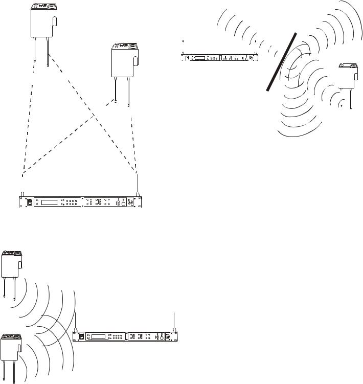
Keep the distance between the base station and the beltpacks as short as possible. The greater the distance, the weaker the signal. Make sure the “signal paths” between the base station and beltpacks are unobstructed. You should be able to visibly locate the base station antennas at all times for best perfor- mance.
xeleT
Attempting to operate the wireless intercom system through or around walls, ceilings, metal objects, etc. will reduce system range and performance.
xeleT
xeleT
 700 FEET
 100 FEET
Figure 16
Operating System Near Obstructions
DO NOT - mount the base station 1/2-wave antennas on, or next to metal, such as beams, walls with metal studs, equip- ment racks, etc. This also applies to the antennas when assem- bled directly to the Base Station. This will “detune” the
antennas which can result in noise or loss of RF signal at the
Figure 14
Base Station, see Figure 17.
Distance Between base station and beltpack
xeleT
RadioComTM
TR-800
xeleT
TM
RadioCom
TR-800
RadioComä |
BTR-800 |
|
|
|
ClearScan |
1 2 3 4 |
|
|
|
|
PORTABLE STATION CONNECT |
INTERCOM A |
INTERCOM B |
AUXILIARY |
Figure 15
Keeping Site Clear to Antenna
5-3
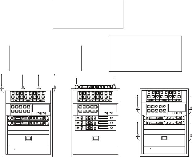
2.Placing the BTR on top of a shelf or equipment rack unobstructed without remoting the antennas is OK.
1.Placing BTRs in a shelf or equipment rack and using remote antennas is OK.
3.Placing BTRs in a shelf or equipment rack with the antennas mounted on the back of the BTR or the side of the rack is BAD.
RadioCom |
BTR-800 |
Telex |
Telex |
Telex |
|
RadioCom |
BTR-800 |
|
RadioCom |
BTR-800 |
|
RadioCom |
BTR-800 |
|
RadioCom |
BTR-800 |
Telex |
SC-600 |
|
Telex |
SC-600 |
|
UHF ANTENNA SPLITTER/COMBINER |
|
UHF ANTENNA SPLITTER/COMBINER |
|
||
|
|
#1 |
#2 |
|
#3 |
Figure 17
Antenna Placement
Improving Reception and Increasing
Range
Keeping the distance from the base station and beltpack as short, and unobstructed as possible will produce the most reli- able performance.
The base station is supplied with two antennas. This should provide satisfactory system performance in most applications. System range can be enhanced by remoting the 1/2-wave an- tennas. The ½ wave antennas are ground plane independent, so a ground plane is not required for good performance.
5-4
Base Station Set-up
INTERCOM
INTERFACE
|
|
|
|
|
|
|
|
|
|
|
POWER CONNECTION |
|
RECEIVE |
BTR-800 |
|
INTERCOM A |
INTERCOM B |
AUXILIARY AUDIO |
|
|
|
||||
FCC ID: B5DM514 |
|
|
100-240 VAC 50-60 Hz |
|
||||||||
|
|
CANADA 1321231218A |
|
2 WIRE |
PUSH |
2 WIRE PUSH |
PUSH |
|
STAGE ANNOUNCE |
|
||
|
TRANSMIT |
BASE STATION |
|
L |
|
L |
|
|
|
|
|
|
|
|
O |
4 WIRE |
O |
4 WIRE |
|
|
|
|
|||
|
POWER |
LINK |
RELAY |
O |
O |
|
|
|
|
|||
|
|
|
|
P |
|
P |
|
|
|
|
|
|
|
|
|
|
CONTACT |
|
|
|
|
|
|
||
|
|
I/C |
|
T |
|
T |
|
|
|
Telex |
|
|
HIGH |
NORM |
|
|
|
|
|
|
TRANSMIT |
||||
|
|
R |
|
R |
|
|
|
Telex Communications, Inc. |
||||
|
|
H |
|
H |
|
|
|
|
||||
ON |
OFF |
RTS |
|
|
U |
|
U |
|
|
|
|
|
|
TELEX CLEARCOM |
|
|
|
|
|
INPUT |
OUTPUT |
OUTPUT |
POWER |
MADE IN USA |
|
|
|
|
|
|
|
|
|
|||||
TRANSMIT
SWITCHES
INTERCOM
SWITCH
Figure 18
Base Station - Rear Panel
Location
Locate the base station with the front and rear of the unit ac- cessible so that switches may be set and connections made. Place the transmit and receive antennas on the base station. Make sure the antenna’s color band match the color dot near each antenna. See “Antenna Information” section for more in- formation on choosing a proper operating location.
Power Connection
Plug the supplied power cord into the unit. The base station has an IEC power receptacle that accepts 100 – 240 VAC, 50 – 60 Hz. The specific receptacle type is an IEC 60320/C14. The cord it accepts is an IEC 60320/C13. These cords are common and available through many retail hardware/electronic stores if the cord is lost.
Transmit Switches
There are two switches located on the lower left side of the rear panel. The upper switch sets the transmit power levels to high or normal. The lower switch turns the transmitters on or off.
Transmit Power
Set the power level to normal if using the beltpacks at c l o s e t o me d i u m d i s t a n ce s ( <2 0 0 f e e t, 1 6 1 m, line-of-sight) from the base station. Set the power level to high if using the beltpacks at a distance (>200 feet, 161m, line-of-sight) from the base station.
On/Off
Set the transmitter switch to on for normal use. In the off position both base station transmitters are disabled. Set- ting the switch to off will disable all the beltpacks from hearing anyone else or even their own sidetone.
5-5
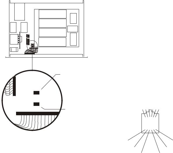
Internal Transmit Switches
Internal to the BTR-800 are two transmit switches which en- able a user to turn on or off the two transmitters individually. See Figure 19 for the location. The top cover of the base sta- tion must be removed for access. The switch closest to the front panel controls transmitter 1 (audio channel A). The switch behind that is transmitter 2 (audio channel B). The de- fault switch position is to the left if you are facing the front of the base station. This is the “ON” position for the transmitters.
In the normal use of the BTR-800, there is no need to access these switches. They are used to test the transmitters individu- ally at the factory.
Intercom Switch
The RadioCom® wireless system can be interfaced to RTS, TW, Audiocom® (Telex), Clear-Com®, RTS matrix and other intercom (I/C) systems. Set the Intercom switch on the rear of the unit to the appropriate system and connect the system to the base station. The two intercom channels on the rear of the base station have loop-thru male and female XLR connections for two-wire systems and RJ-11 type jacks for four-wire sys- tems.
This switch only affects the two-wire intercom systems. The functions of the I/C XLRs change depending on the intercom selected. Please see Section 12 for pinout information of the different two-wire intercom systems.
BACK |
FRONT |
Transmitter 2
ON |
|
|
|
|
|
|
|
S3 |
|
|
|
|
|
|
|
||
|
|
|
|
|
|
|
OFF |
|
|
|
|
|
|
|
|
||
|
|
|
|
|
|
|
|
S4 |
|
|
|
|
|
|
|
|
|
ON |
|
|
|
|
|
|
|
OFF |
|
|
|
|
|
|
|
||
|
|
|
|
|
|
|
|
Transmitter 1 |
|
|
|
|
|
|
|
|
Figure 19
Internal Transmit Switches
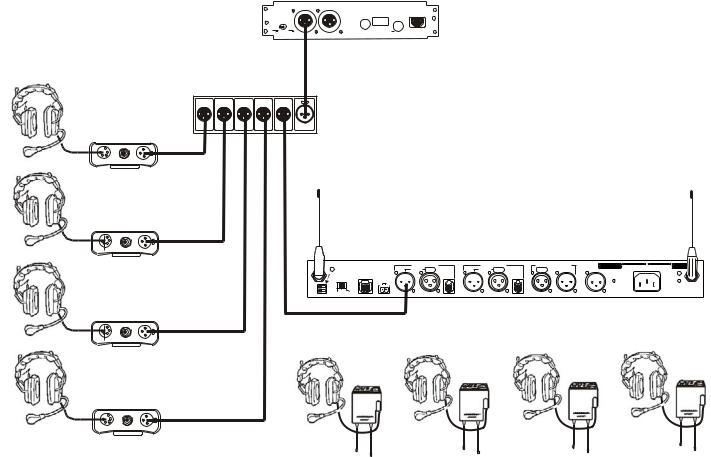
Intercom Interface
Telex (Audiocom®) and Clear-Com® intercom systems re- quire one cable for intercom A and one cable for intercom B in order to interface two channels of intercom to the base station. This interfacing is done through the I/C A and B 3-pin XLR connectors on the rear of the unit.
RTS TW intercoms only need to connect one 3-pin cable to one of the four intercom XLR connectors since two channels of audio are carried on one cable. The intercom switch paral- lels the four XLR connectors when in RTS mode. RTS chan- nel 1 is placed on intercom A and RTS channel 2 is placed on intercom B as long as the RTS TW input to the base station is wired as in Section 12.
Four-wire intercom systems require one cable for intercom A and one cable for intercom B in order to interface two chan- nels of four-wire intercom to the base station. This interfacing is done through the I/C A and B RJ-11 type jacks on the rear of the unit. See Figure 20 for the pinout of the RJ-11 jacks.
PIN |
6 5 4 |
3 2 1 |
|||||||
|
|
|
|
|
|
|
|
|
|
|
|
|
|
|
|
|
|
|
|
|
|
|
|
|
|
|
|
|
|
NC |
NC |
AUDIO IN - |
AUDIO IN + |
AUDIO OUT - |
AUDIO OUT + |
Figure 20
RJ-11 Type/ Four-wire Pinout
5-6
MODEL PS15 |
|
OUTPUTS |
RTS SYSTEMS, BURBANK CALIFORNIA MADE IN U.S.A. |
POWER SUPPLY |
|
J1, J2 CONNECT TO |
|
O/N 9000678600 |
J1 |
J2 |
TW INTERCOM SYSTEM COMPONENTS |
|
|
|
REFER TO OPERATION MANUAL |
INTERCOM
|
|
|
J3 |
IMPEDANCE |
|
|
|
|
SELECT |
|
|
NORM |
DUAL |
|
|
200 |
400 |
|
AUDIO |
|
CHN 1 |
CHN 1 |
COUPLING |
|
|
|
CM1-CM2 |
RTS DISTRIBUTION |
|
|
|
PANEL (TW5W) |
|
|
|
FUSE
0.5A S8/120 VAC
TIP-CH1
RING-CH2
SLEEVE-COM
CAUTION
FOR CONTINUED PROTECTION AGAINST FIRE REPLACE ONLY WITH SAME TYPE FUSE.
POWER SUPPLY
(PS15)
HEADSET LINE
BP-318
HEADSET LINE
BP-318 |
R |
VE |
|
BTR-800 |
|
INTERCOM A |
INTERCOM B |
AUXILIARY AUDIO |
|
|
|
|||
|
FCC ID: B5DM514 |
CONTACT |
|
100-240 VAC 50-60 Hz |
|
|||||||||
|
|
CANADA 1321231218A |
P |
PUSH |
P |
PUSH |
|
STAGE ANNOUNCE |
|
|
||||
|
|
|
|
2 WIRE |
2 WIRE PUSH |
|
|
|
||||||
|
|
|
TRANSMIT |
BASE STATION |
|
L |
|
L |
|
|
|
|
|
|
|
|
|
|
O |
|
O |
|
|
|
|
|
|||
|
|
|
POWER |
|
LINK |
RELAY |
O |
4 WIRE |
O |
4 WIRE |
|
|
|
|
|
HIGH |
NORM |
I/C |
|
|
T |
|
T |
|
|
Telex |
|
TRANSMIT |
|
|
|
|
R |
|
R |
|
|
Telex Communications, Inc. |
|
|||||
|
|
|
H |
|
H |
|
|
|
|
|||||
|
ON |
OFF |
RTS |
|
|
|
U |
|
U |
|
|
|
|
|
|
TELEX CLEARCOM |
|
|
|
|
|
INPUT |
OUTPUT |
OUTPUT |
POWER |
MADE IN USA |
|||
|
|
|
|
|
|
|
|
|
|
|||||
BTR-800
HEADSET LINE
BP-350
HEADSET LINE
BP-350
TR-800’s
or
TR-825’s
Figure 21
Example Interface to an RTS TW System
5-7
 Loading...