

Page 1
VOIP
Virtual
Keypanel
User Manual
9350-7797-000 Rev B 10/2004
Telex Communications
12000 Portland Avenue South
Burnsville MN 55337
Page 2

2
Page 3

STOP!
There are two versions of the software that can be installed from
installation cd, English and Japanese. Please following the
installation instructions for the keypanel you desire.
3
Page 4

PROPRIET AR Y NOTICE
The RTS product information and design disclosed herein were originated by and are the property of Telex Com-
munications, Inc.. Telex reserves all patent, proprietary design, manufacturing, reproduction, use and sales rights
thereto, and to any article disclosed therein, except to the e xtent rights are expressly granted to others.
COPYRIGHT NOTICE
Copyright 2004 by Telex Communications , Inc. All rights reserved. Reproduction in whole or in part without prior
written permission from Telex is prohibited.
UNPACKING AND INSPECTION
Immediately upon receipt of the equipment, inspect the shipping container and the contents carefully for any
discrepancies or damage. Should there be any, notify the freight company and the dealer at once.
WARRANTY
See the enclosed warranty card.
CUSTOMER SUPPORT
Technical Questions should be directed to:
Customer Service Department
RTS/Telex
12000 Portland Ave nue South
Burnsville, MN 55337 U.S. A.
T elephone: 800-392-3497
Fax: 800-323-0498
4
Page 5

Contents
Chapter 1 - Introduction ........................................................................................7
Screen Descriptions ......................................................................................................................... 12
KP-32 Skin ....................................................................................................................................... 12
KP-812 Lever Key Skin .................................................................................................................... 15
KP-812 Push Button Skin................................................................................................................. 15
Settings Screen................................................................................................................................ 17
Chapter 2 - VOIP VKP Menu System................................................................. 19
Keypanel Menu ................................................................................................................................. 19
MENU SYSTEM, MENU ACCESS.................................................................................................... 19
MENU SYSTEM, DISPLA Y MENU .................................................................................................... 20
MENU S YSTEM, KEY ASS IGN MEN U.............................................................................................. 21
KEY OPTION MENU ........................................................................................................................ 24
Key Option Menu, Chime ................................................................................................................. 24
Key Option Menu, Key Groups ......................................................................................................... 24
Key Options, Solo ............................................................................................................................ 25
SERVICE MENU .............................................................................................................................. 26
Service, Mic Gain ............................................................................................................................. 26
Service, Reset Cfg ........................................................................................................................... 26
Service, Save Cfg ............................................................................................................................ 27
Service, T on Gen .............................................................................................................................. 27
Right-Click Menu .............................................................................................................................. 28
MENU SYSTEM, MENU ACCESS.................................................................................................... 28
File, Reset Cfg ................................................................................................................................. 28
File, Save Cfg................................................................................................................................... 28
File, Exit............................................................................................................................................ 29
Menu, Display................................................................................................................................... 29
Menu, Ke y Assign ............................................................................................................................. 29
Menu, Key Options ........................................................................................................................... 32
Key Option Menu, Chime ................................................................................................................. 32
Key Option Menu, Key Groups ......................................................................................................... 32
Key Options, Solo ............................................................................................................................ 33
MENU, SERVICE ............................................................................................................................. 34
Service, Settings .............................................................................................................................. 34
Service, Mic Gain ............................................................................................................................. 34
Service, T on Gen .............................................................................................................................. 35
Service, Copy CWW........................................................................................................................ 35
Service, Copy Key............................................................................................................................ 35
Service, Latch Enable ...................................................................................................................... 36
Service, Flash Timeout..................................................................................................................... 36
Chapter 3 - VKP Menu System Quick Reference .............................................. 37
5
Page 6

6
Page 7

Chapter
1
Introduction
General Description
The RTS™ VOIP Virtual Ke ypanel (VKP) is a Windows®-based application that allows any user to hav e a fully functioning
RTS™ Matrix Intercom User Station on their PC.
The Virtual Ke ypanel application connects via the PC’s Ethernet connection to any path that can support standard IP
protocols, including LAN, WAN, and VPN.
The RTS™ Virtual Keypanel Application is compatib le with an y RTS Matrix Intercom equipped with the R V ON interf ace.
The Virtual Ke ypanel brings a new le v el of enterprise-wide and remote access to your R TS Matrix Intercom System.
Features
VOIP
:
Using the same Voice Over IP technology as the RVON cards, the VOIP Virtual Keypanel is compatib le with any
RTS™ Matrix Intercom system equipped with the RVON interfaces.
GUI Interface Skins:
The RTS™ Virtual Keypanel has three standard interface skins - KP-32, KP-812 Lever Key and KP-812 Push
button styles. Other skins can be easily created to fit the needs of individual environment giving a highly application specific configuration option. Contact Telex for special requirements.
Convenience
With VOIP Virtual Keypanel running under Windows®, no special dedicated hardware is required. The same PC that
runs your general purpose applications, such as spreadsheets, word processors, AZedit, can SIMULTANEOUSLY
function as a matrix keypanel.
Worldwide Connections
Remote communications using V OIP Virtual Keypanel and a compatible computer , R TS™ Matrix communications
can be accessed from anywhere in the world that an IP compliant LAN connection can be made.
Installation
Insert the USB Security Dongle, choose the English or Japanese version, install the software, connect to the LAN,
Done.
:
:
:
7
Page 8
Specifications
Operating System: Windows 2000 or higher
Sound Card: Must be detected as an audio device
Periphe rals: Microphone and Speaker/Headset
Hard Drive: at least 10MB space required
Connections: Ethernet Connection, USB Security Dongle
Protocols: G.711µ
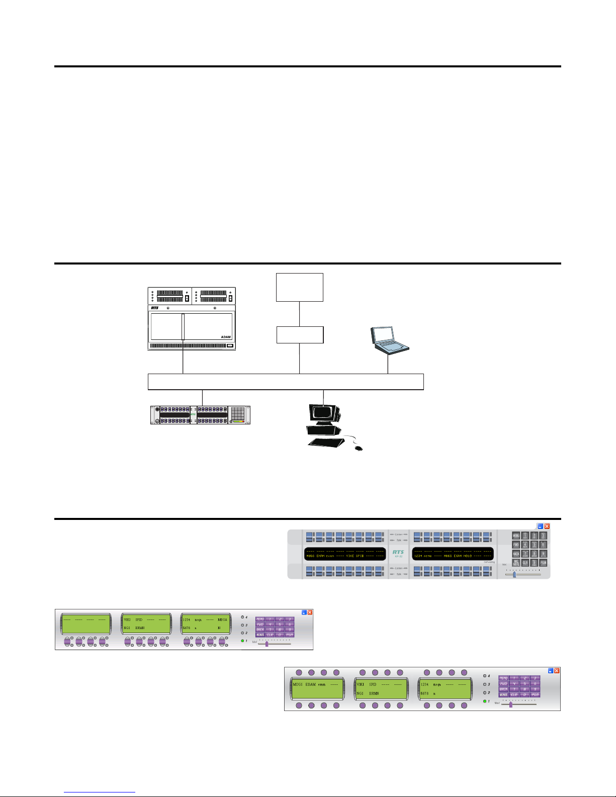
System Diagram
RTS™ Cs9500
Zeus
ADAM CS
™
VOIPVirtual Keypanel
on Laptop
RVON-8Card
AdvancedDigital Audio Matrix
RVON-I/O
Mic
Headset
4
3
Virtual Keypanel Skins
KP-812 Lever Key Keypanel
------------ ---- ---- ---- ---- ----
KP12OKP4ANDY KP32 DAN KP96 TIF1 KP12
125
KP-32 with RVON-1
Listen
Talk
™
------------ ---- WKP4 ---- WKP4
1F01DAN KP96 KP96 SL03 KP12 M009
KP-32
Listen
Talk
ETHERNET
NUM
PL
AUTO
Headset
MENU
1
2
3
SLIST
IFB
ISO
Vol.Sel.
PHONE
PREFIX
FWD
6
4
5
RELAY
TYPE
COPY CW
E-PNL
BACK
9
7
8
EX COPY
DISPLAY
MULT
MUTE CLR PGM
0
Call waiting
FUNC
Vol.
VOIP Virtual keypanel
on Desktop PC
KP-32 Lever Key Keypanel
KP-812 Pushbutton Keypanel
8
Page 9
Installation and Setup
Before installing the V OIP Virtual Keypanel (VKP) on your PC, y ou need to configure the network connec-
tion so it will function properly with the VKP software.
IMPORTANT: The VKP application supports static IP Addressing. Dynamic Addressing is not supported
at this time.
NOTE: Contact your IT Administrator to verify the static IP Address for your machine.
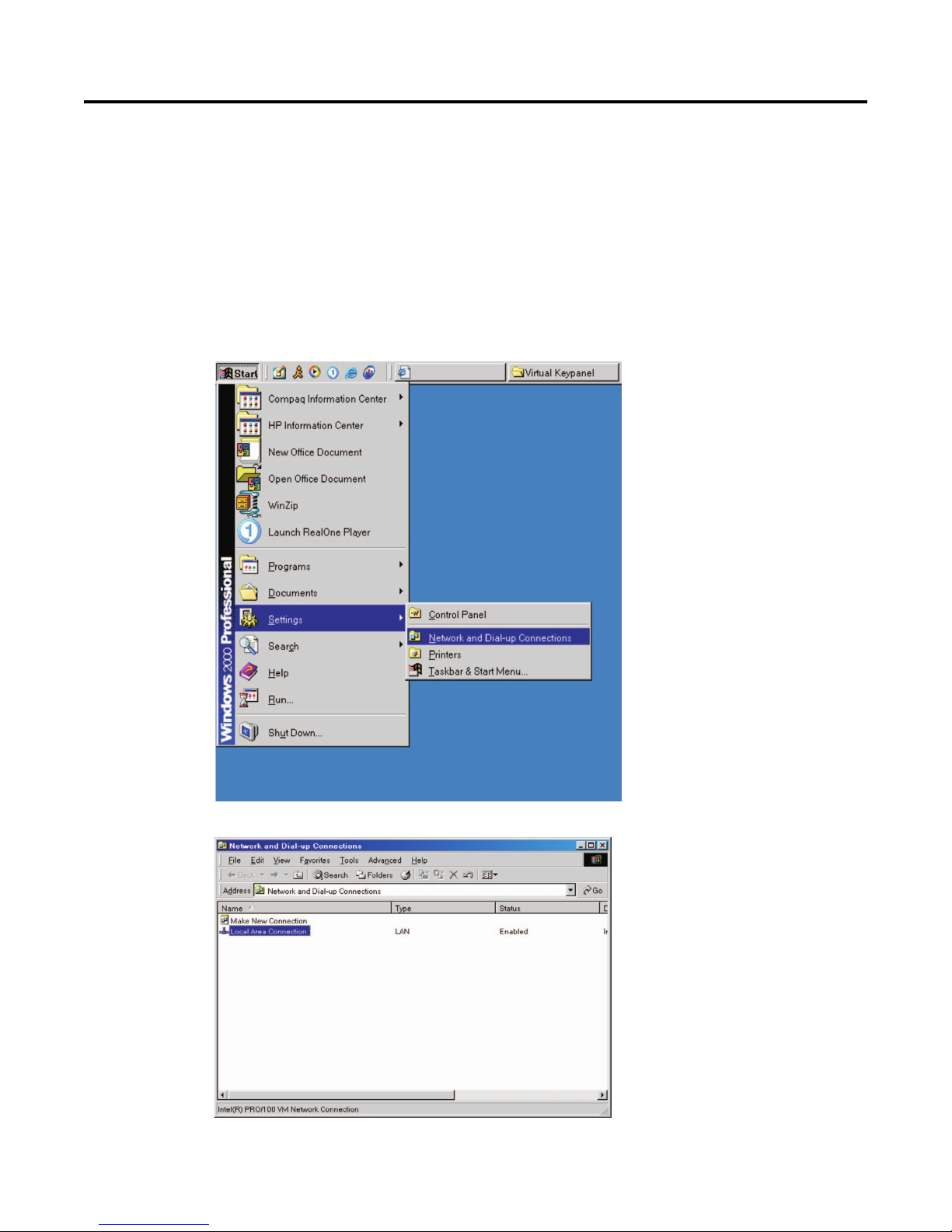
T o configure your netw ork connection, do the following:
1. From the Start Menu, select Settings and then Network and Dial-up Connections.
The Network and Dial-up Connections screen appears.
9
Page 10
2. Double-click Local Area Connection.
The Local Area Connection Status screen appears.
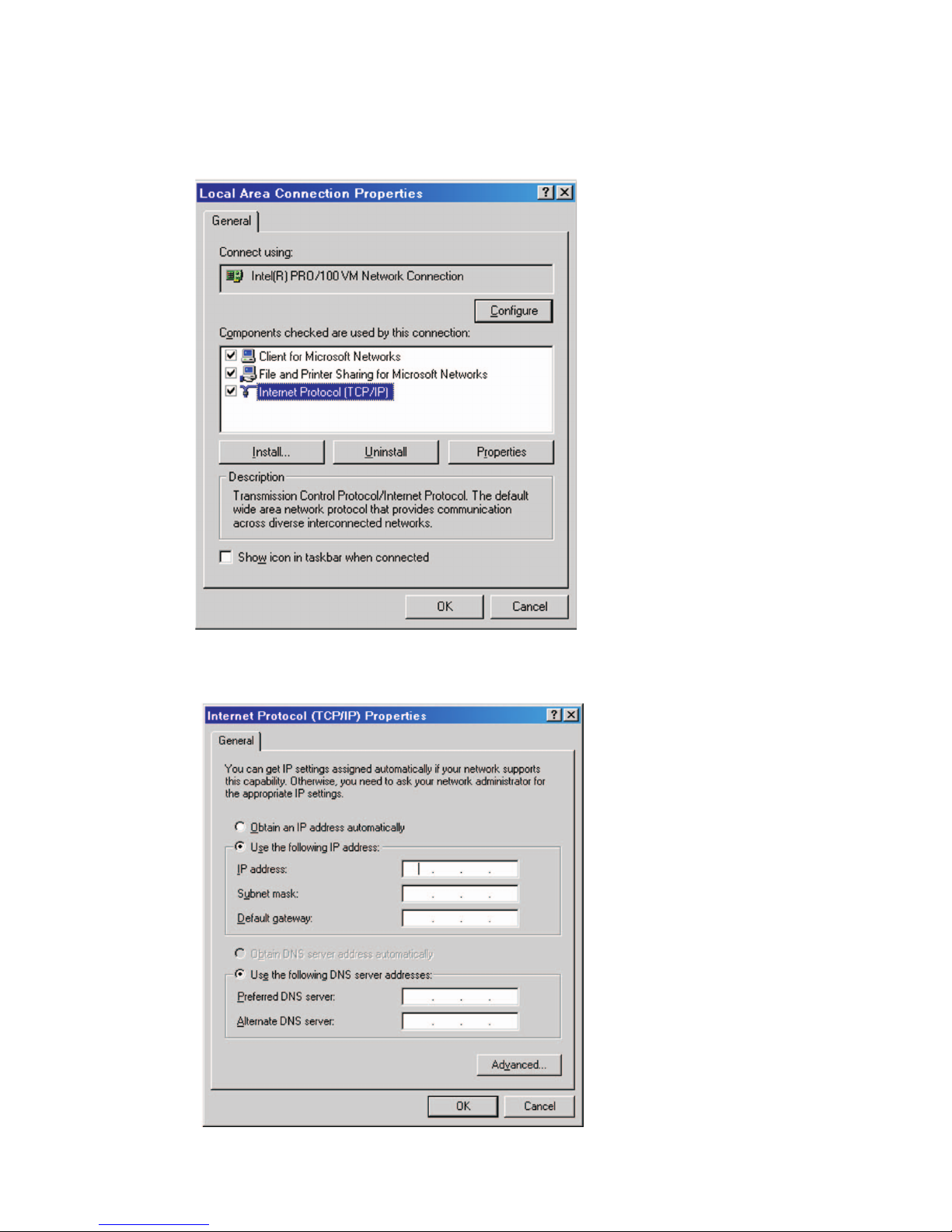
3. Click Properties.
The Local Area Connection Properties screen appears
.
4. Highlight Internet Protocol (TCP/IP) and then click Properties.
The Internet Protocol (TCP/IP) Properties screen appears
.
10
Page 11

5. Select the Use the following IP address: checkbox.
The lower portion of the screen becomes operational.
NOTE: This checkbox allows Static IP Addressing. If it is already checked, your IP, subnets, and
gatewa y may already exist. V erify this with your Netw ork Administrator .
6. In the IP address field, enter the IP address of the PC you intend to use.
7. In the Subnet mask field, enter the Subnet mask that the PC will use.
8. In the Default gateway field, enter the Default gateway address the PC will use.
9. Verify the Use the following DNS server addresses checkbox is selected.
10. In the Preferred DNS server field, enter the Preferred DNS server address.
11. In the Alternate DNS server field, enter the Alternate DNS server address.
12. Click OK to accept the changes.
Click Cancel to exit without making changes.
13. Once you hav e configured y our Static IP Address, insert the VKP CD and Security dongle. Follow
the installation instructions on the cd.
Warning: If the
Obtain an IP Address
check box is selected, you are using dynamic addressing. If you
change the Addressing from dynamic to static, contact your network administrator to ensure your new
static address will be identified on the network.
11
Page 12
Screen Descriptions
The VOIP Virtual Keypanel gives you the ability to customize the application interface skin. A skin is an element of
a GUI (graphical user interface) that can be changed to alter the look of an application without affecting the functionality of the program. The VKP has currently three diff erent skins that can be used.
The different skins are:
KP-32
KP-812 Lever Key
KP-812 Push Button
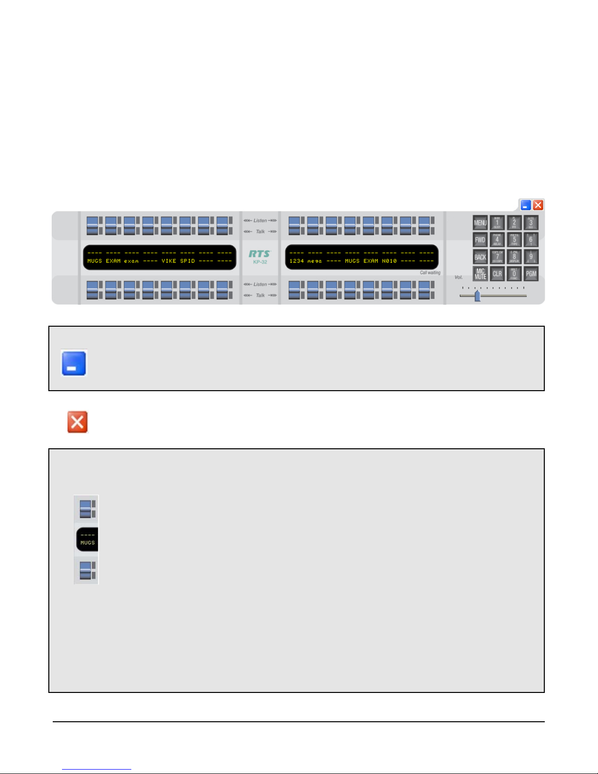
KP-32 Skin
Field Type Description
Minimize button Use the Minimize button to hide a window currently being viewed without shutting
down the program responsible for it.
1. Click the Minimize button to minimize the screen currently being viewed.
The window minimizes.
Exit button Use the Exit button to shut the window or terminate the program currently being
viewed.
1. Click the Exit button to close the screen currently being viewed.
The window closes.
Talk/Listen
Keys lever keys Use the Talk/Listen key to either talk, by clic king the lower portion of the lever
key. Or listen, by clicking the upper portion of the lever key.
NOTE: In the J apanese v ersion of the softw are, the talk LED is Red, while the
Listen LED is green.
Also, When a user is talking with someone else an In-Use LED lights green to let
other callers know the user is talking to someone else. For example, when user A
calls user B, user C will see users A and B are talking because the talk LEDs on
user C’s ke ypanel are lit green.
1. Click the Talk key of the port you want to talk with.
The talk channel is open.
1. Click the Listen key (upper portion of the lever key) of the port you want to
listen.
The listen channel is open
.
NOTE: On the keypanel, Talk assignments appear in all uppercase letters, while
Listen assignments appear in lower case letters.
12
Page 13

Display P anel display Use the Display Panel to display the diff erent ports associated with each of the
lever keys. The KP-32 can have up to 31 ports assigned.
Menu button Use the MENU button to activate the underlying menu structure for the VOIP VKP.
When selected, the top-level men u appears in the CWW (call waiting window). The
FWD, BACK, and PGM button allow you to na vigate through the menu structure.
1. Click MENU.
The V OIP VKP menu structure appears in the CWW window .
FW D button Use the FWD button to scroll forward through the V OIP VKP menu.
1. Clic k FWD.
The next menu item in the list appears.
BACK button Use the BACK button to scroll backward through the V OIP VKP menu.
1. Clic k BACK.
The previous menu item in the list appears.
Mic Mute button Use Mic Mute button to m ute the microphone output audio.
1. To enable Mic Mute, click MIC MUTE.
Mic Mute is enabled. The mic mute button is depressed.
1. To disable Mic Mute, click MIC MUTE.
Mic Mute is disabled. The mic mute button is not depressed.
CLR button Use the CLR button to clear and close the VKP men u structure.
1. Click CLR.
The menu clears and closes, returning to normal operation mode.
PGM button The PGM button accepts the menu selection and moves you futher down into the
menu selection.
1. Click PGM.
The menu selection you made is accepted and the next lowest level in the
menu structure appears.
Number
(pad) 1-9 button(s) Use the Number Pad to enter in port alphas and IP (Internet Protocol) addresses.
1. Enter the appropriate number by clicking the appropriate numerical pads.
Volume
Adjust slider Use the Volume Adjust slider to adjust the ke ypanel v olume le vel.
1. Drag the Volume Adjust slider right to increase the volume, or left to decrease
the volume.
13
Page 14

KP-812 Lever Key & KP-812 Pushbutton
Field Type Description
Minimize button Use the Minimize button to hide a window currently being viewed without shutting
down the program responsible for it.
1. Click the Minimized button to minimize the screen currently being viewed.
The window minimizes.
Exit button Use the Exit button to shut the window or terminate the program currently being
viewed.
1. Click the Exit button to close the screen currently being viewed.
The window closes.
Talk/Listen
Keys lever keys Use the Talk/Listen key to either talk, by clicking the lower portion of the leve r
key. Or listen, by clicking the upper portion of the lever key.
NOTE: In the J apanese version of the software, the talk LED is Red, while the
Listen LED is green.
Also, When a user is talking with someone else an In-Use LED lights green to let
other callers know the user is talking to someone else. For example, when user A
calls user B, user C will see users A and B are talking because the talk LEDs on
user C’s k eypanel are lit green
1. Click the Talk key of the port you want to talk with.
The talk channel is open.
1. Click the Listen key (upper portion of the lever key) of the port you want to
listen.
The listen channel is open
.
NOTE: On the keypanel, Talk assignments appear in all uppercase letters, while
Listen assignments appear in lower case letters.
14
Page 15

Display P anel display Use the Display Panel to display the different ports associated with each of the
lev er k e ys . The KP-32 can have up to 11 ports assigned.
1-4 LED display The 1 - 4 LED display lights show which key assignment page is active.
Menu button Use the MENU button to activate the underlying menu structure for the VOIP VKP.
When selected, the top-level men u appears in the CWW (call waiting window). The
FWD, BACK, and PGM button allow you to na vigate through the menu structure.
1. Click MENU.
The V OIP VKP menu structure appears in the CWW window .
FW D button Use the FWD button to scroll forward through the V OIP VKP menu.
1. Clic k FWD.
The next menu item in the list appears.
BACK button Use the BACK button to scroll backward through the V OIP VKP menu.
1. Clic k BACK.
The previous menu item in the list appears.
Mic Mute button Use Mic Mute b utton to mute the microphone output audio.
1. To enable Mic Mute, click MIC MUTE.
Mic Mute is enabled. The mic mute button is depressed.
1. To disable Mic Mute, click MIC MUTE.
Mic Mute is disabled. The mic mute button is not depressed.
CLR button Use the CLR button to clear and close the VKP menu structure.
1. Click CLR.
The menu clears and closes, returning to normal operation mode.
PGM button The PGM button accepts the menu selection and moves you futher down into the
menu selection.
1. Click PGM.
The menu selection you made is accepted and the next lowest level in the
menu structure appears.
Number
(pad) 1-9 button(s) Use the Number Pad to enter in port alphas and IP (Internet Protocol) addresses.
1. Enter the appropriate number by clicking the appropriate numerical pads.
Volume
Adjust slider Use the Volume Adjust slider to adjust the keypanel volume lev el.
1. Drag the Volume Adjust slider right to increase the volume, or left to decrease
the volume.
15
Page 16

Settings Screen
Use the Settings screen to configure the virtual keypanel for individual use.
Feild Type Description
Layout drop down
list Use the Layout drop down list to choose what interface skin users will see when
the Virtual Keypanel is running. There are three different skins to choose between;
KP-32, KP-812 Lever K ey, and KP-812 Pushbutton.
1. F rom the La yout drop down list, either select KP-32, KP-812 Lever Key, or KP-
812 Push Button.
2. Click OK.
The Settings screen closes and the keypanel skin changes to your choice.
Server drop down
list The Server is the port address of the RV ON-8 to which the VKP software con-
nects.
1. From the Server drop down list, select the server you want to connect to.
Local IP drop down
list The Local IP is the IP (Internet Protocol) address of the computer where the V OIP
Virtual Keypanel is installed.
1. From the Local IP drop down list, select the IP address you want to use.
NOTE: A computer can hav e more than one IP address. Separate IP addresses
are associated with each Ethernet card. Therefore, multiple Ethernet cards will
allow for multiple IP addresses.
AUDIO SETTINGS
NOTE: A udio settings are changed in AZedit. F or more inf ormation, see the AZedit User Manual.
Codec display Codec displays the codec used to compress the audio for transmittal. There are
two codecs supported by Telex, G.711µ law and G7.11 A law . The type of Codec
will dictate the quality of audio you hear and the network bandwidth used.
NOTE: If you assign another codec other than G.711 µ or G7.11A law , VKP will
negotiate a G.711 codec.
Frame size display The Frame size displays how much audio is in an individual packet.
VAD display VAD (voice activity detection), saves netw ork bandwidth by stopping the flow of
audio packets when silence is detected.
OK button Accepts the changes and closes the Settings screen
1. Click OK.
The changes are saved and the Settings screen closes.
Cancel button Clears the changes made from the screen and closes the Settings screen.
1. Click Cancel.
The Settings screen closes without saving the changes.
16
Page 17

This page intentionally left blank
17
Page 18

This page intentionally left blank
18
Page 19

Chapter
2
VOIP VKP Menu System
The VKP menu system can be accessed at tw o different points in the Softw are, through the K e ypanel Menu and
through a Main/Sub Menu accessed by clicking the right mouse button. Note, these two menus are similar to each
other, b ut
For a diagram of the menu structures, see page 36.
not exact replicas
.
Keypanel Menu
MENU SYSTEM, MENU ACCESS
To access the menu from the keypad, do the following:
1. Clear all names from the Call W aiting displa y (if not clear) by clic king the Call W aiting key one or
more times.
2. Click Menu.
Display appears in the Call W aiting windo w.
3. Click
4. Click FWD or PGM to enter a menu.
Click BACK to exit a menu.
Within a menu:
• Click
• Click FWD or PGM to select an item.
• Click BACK to cancel a selection or to go back
to the previous menu level.
↓↓↓↓
↓↓ to scroll forward through the list of menus.
↓↓↓↓
↓↓↓↓
↑↑ ↑↑
↓↓ or
↑↑ to scroll.
↓↓↓↓
↑↑ ↑↑
Figure 1. VOIP Virtual Keypanel Number Pad.
19
Page 20

MENU SYSTEM, DISPLAY MENU
Use this menu to display information about the keypanel configuration.
Display Menu, Asgn Type
Displays the talk level 1 assignment types for all keys. Abbreviations for the key assignment types appear
in the alphanumeric displays as follows:
• P-P: Point-to-point talk key
• PL: Party line talk key
• IFB: IFB talk key
• SPCL: Special list talk key
• RLY
(system relay) This key activates a GPI output at the intercom frame, or a relay output at
a UIO-256 or FR9528 frame.
• ISO: Camera ISO talk key
• UPL: UPL resource key
• AC : All-call key
Display Menu, Chans On
Displays an alpha list, in the Call Waiting Window, of all intercom ports that currently have talk crosspoints
closed to this keypanel. Chans ON is typically used to locate an open mic or other open audio source that
needs to be shut off. The most likely cause is typically a talk key that has been left on at a keypanel. In
this case, use the
key to ask the person at the other end to turn off their talk key.
↓↓↓↓
↓↓ and
↓↓↓↓
↑↑↑↑
↑↑ key to scoll through the list of names. You can then press the Call Waiting
↑↑↑↑
Display Menu, Key Groups
↓↓↓↓
Use the
The talk and listen LEDs of the master key will be lit red and the talk and listen LEDs for the slave keys will
be lit green.
Display Menu, Key List
Displays and allows access to all the other assignments on the other keypanel pages that are not currently showing in the keypanel display.
Display Menu, Level 2
Displays the talk level 2 assignments for all keys.
Display Menu, Listen
Displays the listen assignments for all keys.
Display Menu, Matrix
Displays the intercom system name for all talk level 1 key assignments. In non-trunked intercom systems,
the intercom system name is always LOCL (local). In trunked intercom systems, intercom systems are
created in TrunkEdit.
Display Menu, Panel ID
Panel ID displa ys the calculated port number the ke ypanel is connected to. The calculation is based on
the data group that the keypanel is connected to , along with the address switch setting on the keypanel. If
the Address switch is incorrectly set, the wrong Panel ID will display. Panel ID also displays the port alpha
in brackets if the port is not scroll restricted.
↑↑↑↑
↓↓ or
↑↑ key to select Group 1, Group 2, etc. Then press FWD or PGM to display the group.
↓↓↓↓
↑↑↑↑
Display Menu, Version
Displays the firmware version of the keypanel.
NOTE: For software upgrades, contact your Intercom system dealer.
20
Page 21

MENU SYSTEM, KEY ASSIGN MENU
Use the Key Assign menu to assign intercom keys to the keypanel, to adjust listen levels for point-to-point
and party line keys, and to assign setup pages.
To use the key assign menu, do the following:
NOTE: Clear the Call W aiting windo w b y clic king the Call Waiting ke y one or more times .
1. Click Menu.
A menu options list appears in the call waiting window.
2. Click the
3. Click PGM or FWD.
P-P appears in the call waiting window .
The Key Assign menu options appear as a scrollable list consistingof the different key assignments
available:
↓↓↓↓
↓↓ (9 on the number pad) to scroll to Key Assign.
↓↓↓↓
Pt-to-Pt: Assign a key to talk/listen to another intercom port.
Party Line: Assign a key to talk/listen to a party line.
IFB: Assign a key to talk/listen to an IFB.
Spcl List: Assign a key to talk/listen to a special list.
Sys Relay: Assign a key to activate a relay or GPI output.
Camera ISO: Assign a key to talk/listen to an ISO.
UPL Resrc: Assign a key to activate a UPL Resource.
Auto Func: Assign an auto function to a key. (If you select this item, skip the rest of this
procedure and go to “Key Assign Menu, Auto Func”.)
Setup P age: Change the setup page assignments.
4. Click the
5. When the key assignment is found, click PGM to select it.
6. Select the port number or alpha you want to assign to the keypanel key.
7. Click PGM.
Talk Level 1 appears in call waiting window.
8. Click
The options are as follows:
↓↓↓↓
↓↓ (9 on the number pad) to scroll through the options.
↓↓↓↓
↓↓ ↓↓
↓↓ (9 on the number pad) to scroll through the options.
↓↓ ↓↓
• Talk Lvl 1: Assigns only talk level 1.
• Listen: Assigns only Listen.
• Talk + AF: Assigns talk level 1, with auto-follow listen.
• Talk + AL: Assigns talk level 1, with auto-listen.
• Talk + AM: Assigns talk level 1, with auto-m ute listen.
• Talk + AR: Assigns talk level 1, with auto-reciprocal listen.
• Talk + Lvl 2: Assigns talk level 2
NOTE: If you attempt to assign a talk level 2 to a key and there is no talk level 1 assignment, y ou assignment will go on talk level 1. If you change the talk level 1 assignment for a key that also has a talk level 2
assignment, the talk level 2 assignment is erased.
9. When you make your assignment selection, click PGM or FWD.
Tap Key appears in the call waiting window.
10. Click the key you want to assign the assignment.
The assignment alpha appears in the display window of the keypanel key.
11. Click CLR to exit out of the menu structure.
21
Page 22

Key Assign Menu, Matrix
Matrix appears only for trunked intercom systems. You must select a remote intercom matrix before
assigning intercom keys to destinations in that matrix. You do not need to select matrix to assign keys to
destinations in your own matrix. You also do not need to select a matrix when assigning an auto function to
a key.
Key Assign Menu, PT -to-PT
Assigns a key that talks or listens to another intercom port. Note , some pt-to-pt destinations may be nonkeypanel devices that cannot activate talk and listen paths. Therefore, if you want full communication, you
may need to assign both talk and listen on the key .
Key Assign Menu, Party Line
Assigns a key that talks and/or listens to a party line. The will have no effect until members have been
assigned to the party line in AZedit. Note, party line members are usually non-keypanel devices that
cannot activate talk and listen paths. Theref ore , if you want full communication with the party line, you will
need to assign both talk and listen on the key. If all communications will normally be 2-way, you may want
to assign the key as Talk + auto listen.
Key Assign Menu, IFB
By default, all IFBs are restricted and you will see
IFBs you mush check the appropriate Scroll Enable check boxes in AZedit.
Key Assign Menu, Spcl List
Assigns a key that talks and/or listens to a special list. The key will have no effect until members have
been assigned to the special list in AZedit. Note, some or all special list members may be non-keypanel
devices that cannot themselves activate talk and listen paths. Therefore, if you want full communication
with all members of the special list, you may need to assign both talk and listen on the key.
Not Av ail
when you attempt to select this item. To see
Key Assign Menu, Sys Relay
System Relay refers to any of several types of control devices that can exist in the intercom system,
including:
• The 8 GPI outputs from an ADAM frame (J11 on the XCP-ADAM-MC Breakout Panel).
• The 8 GPI outputs from an ADAM CS frame (J903 on the ADAM CS back panel).
• The relay outputs of an FR9528 Relay Frame (RELAY OUTPUTS connector on the FR9528 back
panel).
• The 16 GPI outputs of a UIO-256 Universal Input/Output frame (J5 on the UIO-256 back panel).
Key Assign Menu, Camera ISO
By default, all ISOs are restricted and you will see
ISOs you must select the appropriate check box in AZedit.
Key Assign Menu, UPL Resrc
By default, all UPL resources are restricted and you will see
To see UPL resources you must select the appropriate Scroll Enable check box in AZedit.
Key Assign Menu, Auto Func
1. Press FWD or PGM to select auto functions in the Key Assign menu. Then, press
locate the desired auto-function as follows:
Not Avail
when you attempt to select this item. To see
Not Av ail
when you attempt to select this item.
↓↓↓↓
↑↑↑↑
↓↓ or
↑↑ to
↓↓↓↓
↑↑↑↑
• Auto Follow (AF, for listen keys only)
• AutoListn (AL, for listen keys only)
22
Page 23

• Auto Mute (AM, for listen keys only)
• Auto Recip (AR, for listen keys only)
• All Call (AC, for talk level 1 only)
• DIM (DIM Table function, for talk level 2 on point-to-point k eys only)
2. Click FWD or PGM to select the desired auto function.
Tap Key appears.
3. Click an intercom key to assign the selected auto function.
Click the upper portion of the key to assign auto functions except All Call or DIM. Click the lower
portion of the key for All Call or DIM.
NOTE:
• If the assignment is successful, the abbreviation for the auto function appears in the alpha-
numeric display for that key. However, if you try to assign an auto function to a key that
already has that auto function assigned, the assignment will be ignored. The assignment is
also ignored if scroll enable for auto functions is not selected in AZedit, or if the key you are
trying to assign is restricted.
• You can click CLR to exit and return to normal operation, or click BACK to return to the auto
function menu and make more assignments.
• Trunked intercom systems: Do not select a matrix before assigning auto functions . All auto
functions are assigned using the local matrix menus.
• You do not need to run Save Cfg to store auto function assignments. These are stored in the
intercom system.
Key Assign Menu, Setup Page
Use this menu item to change the setup page assignments on the KP-32, KP-812, EKP-32, EKP-812. One
setup page is used for the top row of keys, and another setup page is used for the bottom row of keys.
1. Click FWD or PGM to select
Page 1 displays.
↓↓↓↓
2. Press
Page 1 : Assign setup page 1 to the KP-32, KP-812, EKP-32, EKP-812
Page 2: Assign setup page 2 to the KP-32, KP-812, EKP-32, EKP-812
Page 3: Assign setup page 3 to the KP-32, KP-812, EKP-32, EKP-812
Page 4: Assign setup page 4 to the KP-32, KP-812, EKP-32, EKP-812
Clear Page: Clear a page from the KP-32, KP-812, EKP-32, EKP-812
3. Click PGM.
Tap Key displays.
4. Click any key in the row where you want to assign the setup.
The key assignments for that page should appear in the displays.
5. You can press
↓↓
to select any of the following:
↓↓↓↓
↓↓↓↓
↓↓
to select and assign another setup page. Or, click CLR to exit.
↓↓↓↓
Setup Page
in the Key Assign menu.
NOTE: You do not need to run Save Cfg to store changes to the setup pages. These are stored in the
intercom.
23
Page 24

KEY OPTION MENU
Use the Key Options menu to set announcement chimes for incoming calls and to assign key groups to
keypanel keys, and to assign the solo option to keys.
Key Option Menu, Chime
Use the Chime setting to add a chime tone to any key f or an incoming call announcement. The chime tone
will activate for 5 seconds after a call is received.
To add a chime tone, do the following:
1. On the keypanel, click MENU.
Display appears in the call waiting windo w.
2. Use the
3. Click PGM or FWD.
Chime appears in the call waiting window.
4. Click PGM.
Tap Key appears in the call waiting window.
5. Click the key of the alpha or port you want to assign the chime.
6. Run Service, Save Cfg to store the chime setting.
NOTE: The chime option will continue on a k ey even if you change the key assignment.
To remove the chime tone from a key, repeat the procedure to add a chime, but click any keys where the
LEDs are lit red to turn them off. Run Save Cfg to store the changes.
↓↓↓↓
↓↓ (9 on the number pad) to scroll to Key Option.
↓↓↓↓
Key Option Menu, Key Groups
Key Groups are groups of users that are associated to each other through a common key, called a master
key. A key group can be created so that when one key (the master key) is activated, all key in the group
will activate. Up to four key groups can be set up.
To create a key group, do the follo wing:
1. On the keypanel, click MENU.
Display appears in the call waiting windo w.
2. Use the
3. Click PGM or FWD.
Chime appears in the call waiting window.
4. Use the
5. Click PGM.
Tap Master appears in the call waiting window. The master key is the key you will click to activate the
group.
6. Click the intercom key you will use as the master.
Both the LEDs next to the key will light red and “tap slaves” will appear in the call waiting window.
Slave keys are the keys that will activate along with the master.
7. Click one or more keys to select slave for that group.
Both LEDs will light green next to each key selected. You can click a key again to remove it from the
group.
8. Click CLR to exit.
Activating the master key will now cause it and all slave keys to activate. The LEDs for each key will
activate according to the current key assignment for that key.
9. Run Service, Save Cfg to store the key group setting.
↓↓↓↓
↓↓ (9 on the number pad) to scroll to Key Option.
↓↓↓↓
↓↓↓↓
↓↓ (9 on the number pad) to scroll to Key Groups.
↓↓↓↓
NOTE: Key group settings will continue on keys even if the key assignments are changed.
24
Page 25

To clear a key group, do the fo llowing:
1. On the keypanel, click MENU.
Display appears in the call waiting window.
2. Use the
3. Click PGM or FWD.
↓↓↓↓
↓↓ (9 on the number pad) to scroll to Key Option.
↓↓↓↓
Chime appears in the call waiting window.
4. Use the
5. Click PGM.
↓↓↓↓
↓↓ (9 on the number pad) to scroll to Key Groups.
↓↓↓↓
Tap Master appears in the call waiting window.
6. Click the current Master Key.
The LEDs next to the ke y will remain lit “tap slaves” will appear in the call waiting windo w.
7. Click all the keys where the LEDs are lit green.
This will turn the LEDs off.
8. Click CLR to exit.
The key group is cleared.
9. Run Service, Save Cfg to store the key group setting.
Key Options, Solo
Use the Solo option to put current, active users on hold and talk to a single user . For example, you may be
in a Key Group and want to ask a question. You can use the solo option to put the key group on hold.
To use the solo option, do the following:
1. On the keypanel, click MENU.
Display appears in the call waiting windo w.
2. Use the
3. Click PGM or FWD.
Chime appears in the call waiting window.
4. Use the
5. Click PGM.
Tap Key appears in the call waiting window.
6. Click the intercom key you want to assign solo.
Both the LEDs next to the key will light red to confirm the assignment. Click the key again if you want
to remove the assignment.
7. Click CLR to exit.
Activating the solo key will cause all other activated keys to turn off. The keys will turn back on when
you turn the solo key off.
8. Run Service, Save Cfg to store the Solo setting.
↓↓↓↓
↓↓ (9 on the number pad) to scroll to Key Option.
↓↓↓↓
↓↓↓↓
↓↓ (9 on the number pad) to scroll to Solo.
↓↓↓↓
NOTE: The Solo option will continue on a k e y e v en if y ou change the k ey assignment.
To remove the solo key option, do the follo wing:
1. On the keypanel, click MENU.
Display appears in the call waiting windo w.
2. Use the
3. Click PGM or FWD.
↓↓↓↓
↓↓ (9 on the number pad) to scroll to Key Option.
↓↓↓↓
Chime appears in the call waiting window.
4. Use the
5. Click PGM.
↓↓↓↓
↓↓ (9 on the number pad) to scroll to Solo.
↓↓↓↓
Both LEDs next to the solo key will light.
6. Click the solo key.
The solo key is cleared.
7. Run Service, Save Cfg to store the Solo setting
25
Page 26

SERVICE MENU
Use the Service menu to access many of the options within the VOIP virtual keypanel, such as Mic Gain,
Tone Gen, Copy CWW, Copy Key, Latch Enable, and Flash Timeout.
NOTE: When using the keypanel menu structure, Save Cfg and Reset Cfg are in the Service Menu. On
the Main Menu, Save Cfg and Reset Cfg are in the File Menu.
Also, Cop y CWW, Copy Key, Latch Enable and Flash Timeout are only av ailab le through the Main Men u.
You cannot use them from the display menu.
Service, Mic Gain
Mic Gain is the level of audio being sent through the microphone . You can set the gain level anywhere
from 0% to 100%. The default mic gain is 60%.
To set the Mic Gain, do the following:
1. On the keypanel, click MENU.
Display appears in the call waiting window.
2. Use the
3. Click PGM.
Mic Gain appears in the call waiting window .
4. Click PGM.
60% appears in the call waiting window .
5. Use the
6. Click CLR to exit.
↓↓ ↓↓
↓↓ (9 on the keypad) to scroll to Service.
↓↓ ↓↓
↓↓↓↓
↓↓ (6 on the keypad) or
↓↓↓↓
↑↑↑↑
↑↑ (9 on the keypad) to decrease or increase the mic gain.
↑↑↑↑
Service, Reset Cfg
Use Reset Cfg to restore all custom settings to the application defaults.
The defaults for Reset Cfg are as follows:
Speaker Volume: 25%
Mic Gain: 60%
Latch Enable: ON
Flash Timeout: ON
Local IP: default (cleared so default is used).
All key options (for each key) are removed
Solo : OFF
Chime : OFF
Groups are cleared
To reset the configuration, do the following:
1. On the keypanel, click MENU.
Display appears in the call waiting window.
2. Use the
3. Click PGM.
Mic Gain appears in the call waiting window .
4. Use the
5. Click PGM.
The system restores all the application defaults.
↓↓ ↓↓
↓↓ (9 on the keypad) to scroll to Service in the menu.
↓↓ ↓↓
↓↓ ↓↓
↓↓ (9 on the keypad) to scroll to Reset Cfg.
↓↓ ↓↓
26
Page 27

Service, Save Cfg
Use Save Cfg to save custom settings that you have made in the Key Option, Key Assign or Service
menus. These settings are stored in non-volatile memory. This ensures protection of y our settings when
you exit the program.
To save the configuration settings, do the following:
1. On the keypanel, click MENU.
Display appears in the call waiting window.
2. Use the
3. Click PGM.
↓↓ ↓↓
↓↓ (9 on the keypad) to scroll to Service in the menu.
↓↓ ↓↓
Mic Gain appears in the call waiting window .
4. Use the
5. Click PGM.
↓↓ ↓↓
↓↓ (9 on the keypad) to scroll to Save Cfg.
↓↓ ↓↓
The system saves configuration settings.
Service, Ton Gen
T one Gen (Tone Generation) gives you the ability to chec k the audio path from the ke ypanel to the matrix
and back.
T o use Tone Gen from the Main menu, do the following:
1. On the keypanel, click MENU.
Display appears in the call waiting window.
2. Use the
3. Click PGM.
Mic Gain appears in the call waiting window .
4. Use the
5. Click PGM.
TONE ON appears. This indicates the Tone Gen is active.
↓↓ ↓↓
↓↓ (9 on the keypad) to scroll to Service in the menu.
↓↓ ↓↓
↓↓ ↓↓
↓↓ (9 on the keypad) to scroll to Tone Gen.
↓↓ ↓↓
NOTE; When Tone Gen is enabled, the keypanel will continue to send audio ev en when the k ey is not
selected. This is important because it will use network bandwidth if not disable after testing.
6. Click the key you wish to check for an audio path.
A tone will sound at the destination keypanel.
27
Page 28

Right-Click Menu
The Right-Click Menu is a right-clic k accessible men u structure f or the VOIP Virtual Keypanel. It is similar the
display panel menu, yet not exactly the same.
The Right-Click Menu contains a File menu item that is not present in the Display Panel Menu. It contains the
Reset Cfg, Save Cfg and an Exit item.
The Right-Click Menu also contains Settings, Copy CWW, Latch Enable and Flash Timeout items in the Service
Menu that are not present in the Display P anel Menu.
MENU SYSTEM, MENU ACCESS
To access the application menu from the Main Menu, do the following:
1. Right-click anywhere on the keypanel.
A pop up menu appears
2. Select the menu item you want to access.
The top level popup menu has the following items. For a complete menu navigation, see page 37.
File
Display
Key Assign
Key Options
Service
.
File, Reset Cfg
Use Reset Cfg to restore all custom settings to the application defaults. To see the defaults, see Service,
Reset Cfg on page 26.
To Reset Cfg, do the following:
1. Right-click on the keypanel.
A popup menu appears.
2. From the popup menu, select File.
The File submenu appears.
3. From the File submenu, select Reset Cfg .
The system restores the application defaults.
File, Save Cfg
Use Save Cfg to save custom settings that have been made in the Key Option, Key Assign, or Service
Menus. These settings are saved on the Matrix in non-v olatile memory to ensure your settings are preserved when you exit the application.
To Save Cfg, do the following:
1. Right-click on the keypanel.
A popup menu appears.
2. From the popup menu, select File.
The File submenu appears.
3. From the File submenu, select Save Cfg.
The system saves your changes.
28
Page 29

File, Exit
Use Exit to close the VOIP Virtual Keypanel application.
To exit out of the VKP application, do the follo wing:
1. Right-click on the keypanel.
A popup menu appears.
2. From the popup menu, select File.
The File submenu appears.
3. From the File submenu, select Exit.
The VKP application closes.
Menu, Display
Use the Display menu to view inf ormation about the keypanel configuration. The Displa y menu options are
as follows:
Assign Type
Chans ON
Key Groups
Key List
Level 2
Listen
Matrix
Panel ID
Ver sion
NOTE: For a more detailed explanation of the Displa y men u options, see page xx.
To access the Display menu, do the following:
1. Right-click on the keypanel.
A popup menu appears.
2. From the popup menu, select Display.
The Display submenu appears.
3. From the Display submenu, select the item you want to view.
Menu, Key Assign
Use the Key Assign menu to assign intercom keys to the keypanel, to adjust listen levels for point-to-point
and party line keys, and to assign setup pages.
The different Key Assign options are as follows:
Pt-to-Pt
Party Line
IFB
Spcl List
Sys Relay
Camera ISO
UPL Resrc
Auto Func
Setup Page
To access the key assign menu, do the following:
1. Right-click anywhere on the keypanel.
The Main menu appears.
2. From the Main menu, select K e y Assign.
The Key Assign submenu appears.
29
Page 30

3. From the Ke y Assign submenu, select the option y ou w ant to use.
An Alpha appears in the call waiting window.
Key Assign Menu, Matrix
Matrix appears only for trunked intercom systems. You must select a remote intercom matrix before
assigning intercom keys to destinations in that matrix. You do not need to select matrix to assign keys to
destinations in your own matrix. You also do not need to select a matrix when assigning an auto function to
a key.
Key Assign Menu, PT -to-PT
Assigns a key that talks or listens to another intercom port. Note , some pt-to-pt destinations may be nonkeypanel devices that cannot activate talk and listen paths. Therefore, if you want full communication, you
may need to assign both talk and listen on the key .
Key Assign Menu, Party Line
Assigns a key that talks and/or listens to a party line. The will have no effect until members have been
assigned to the party line in AZedit. Note, party line members are usually non-keypanel devices that
cannot activate talk and listen paths. Theref ore , if you want full communication with the party line, you will
need to assign both talk and listen on the key. If all communications will normally be 2-way, you may want
to assign the key as Talk + auto listen.
Key Assign Menu, IFB
By default, all IFBs are restricted and you will see
IFBs you mush check the appropriate Scroll Enable check boxes in AZedit.
Not Av ail
when you attempt to select this item. To see
Key Assign Menu, Spcl List
Assigns a key that talks and/or listens to a special list. The key will have no effect until members have
been assigned to the special list in AZedit. Note, some or all special list members may be non-keypanel
devices that cannot themselves activate talk and listen paths. Therefore, if you want full communication
with all members of the special list, you may need to assign both talk and listen on the key.
Key Assign Menu, Sys Relay
System Relay refers to any of several types of control devices that can exist in the intercom system,
including:
• The 8 GPI outputs from an ADAM frame (J11 on the XCP-ADAM-MC Breakout Panel).
• The 8 GPI outputs from an ADAM CS frame (J903 on the ADAM CS back panel).
• The relay outputs of an FR9528 Relay Frame (RELAY OUTPUTS connector on the FR9528 back
panel).
• The 16 GPI outputs of a UIO-256 Universal Input/Output frame (J5 on the UIO-256 back panel).
Key Assign Menu, Camera ISO
By default, all ISOs are restricted and you will see
ISOs you must select the appropriate check box in AZedit.
Key Assign Menu, UPL Resrc
By default, all UPL resources are restricted and you will see
To see UPL resources you must select the appropriate Scroll Enable check box in AZedit.
Key Assign Menu, Auto Func
1. Click FWD or PGM to select auto functions in the Key Assign menu. Then, press
locate the desired auto-function as follows:
Not Avail
when you attempt to select this item. To see
Not Av ail
when you attempt to select this item.
↓↓↓↓
↑↑ ↑↑
↓↓ or
↑↑ to
↓↓↓↓
↑↑ ↑↑
• Auto Follow (AF, for listen keys only)
• AutoListn (AL, for listen keys only)
30
Page 31

• Auto Mute (AM, for listen keys only)
• Auto Recip (AR, for listen keys only)
• All Call (AC, for talk level 1 only)
• DIM (DIM Table function, for talk level 2 on point-to-point k eys only)
2. Click FWD or PGM to select the desired auto function.
Tap Key appears.
3. Click an intercom key to assign the selected auto function.
Click the upper portion of the key to assign auto functions except All Call or DIM. Click the lower
portion of the key for All Call or DIM.
NOTE:
• If the assignment is successful, the abbreviation for the auto function appears in the alpha-
numeric display for that key. However, if you try to assign an auto function to a key that
already has that auto function assigned, the assignment will be ignored. The assignment is
also ignored if scroll enable for auto functions is not selected in AZedit, or if the key you are
trying to assign is restricted.
• You can click CLR to exit and return to normal operation, or click BACK to return to the auto
function menu and make more assignments.
• Trunked intercom systems: Do not select a matrix before assigning auto functions . All auto
functions are assigned using the local matrix menus.
• You do not need to run Save Cfg to store auto function assignments. These are stored in the
intercom system.
Key Assign Menu, Setup Page
Use this menu item to change the setup page assignments on the KP-32, KP-812, EKP-32 and EKP-812.
One setup page is used for the top row of keys, and another setup page is used for the bottom row of keys.
1. From the Ke y Assign submenu, select the page y ou want to work with.
Page 1 displays.
Page 1 : Assign setup page 1 to the KP-32, KP-812, EKP-32, EKP-812
Page 2: Assign setup page 2 to the KP-32, KP-812, EKP-32, EKP-812
Page 3: Assign setup page 3 to the KP-32, KP-812, EKP-32, EKP-812
Page 4: Assign setup page 4 to the KP-32, KP-812, EKP-32, EKP-812
Clear Page: Clear a page from the KP-32, KP-812, EKP-32, EKP-812
2. Click PGM.
Tap Key displays.
3. Click any key in the row where you want to assign the setup.
The key assignments for that page should appear in the displays.
↓↓↓↓
4. You can press
NOTE: You do not need to run Save Cfg to store changes to the setup pages. These are stored in the
intercom.
↓↓
to select and assign another setup page. Or, click CLR to exit.
↓↓↓↓
31
Page 32

MENU, KEY OPTIONS
Use the Key Options menu to set announcement chimes for incoming calls, to assign key groups to
keypanel keys, and to assign the solo option to keys.
Key Option Menu, Chime
Use the Chime setting to add a chime tone to any key for an incoming call announcement. The chime tone
will activate for 5 seconds after a call is received.
To add a chime tone, do the following:
1. Right-click anywhere on the keypanel.
The Main menu appears.
2. From the Main menu, select K ey Option.
The Key Option submenu appears .
3. From the K e y Option submen u, select Chime.
Tap Key appears
4. Click the key where you want to add the Chime tone.
Both red LEDs are lit. The Chime is enab led.
4. Run File, Save Cfg. to save the chime setting.
NOTE: The chime option will continue on a key even if you change the key assignment. To remove the
chime tone from a key, repeat the procedure to add a chime, but click any ke ys where the LEDs are lit red
to turn them off. Run File, Save Cfg to store the changes.
Key Option Menu, Key Groups
Key Groups are groups of users that are associated to each other through a common key, called a master
key. A key group can be created so that when one key (the master key) is activated, all key in the group
will activate. Up to four key groups can be set up.
To create a key group, do the follo wing:
1. Right-click anywhere on the keypanel.
The Main menu appears.
2. From the Main menu, select Key Option.
The Key Option submenu appears .
3. From the Key Option submenu, select Key Groups.
The Key Groups submenu appears.
4. From the Key Groups submenu, select the page you w ant to use.
Tap Master appears in the call waiting window. The master key is the key you will click to activate the
group.
6. Click the intercom key you will use as the master.
Both the LEDs next to the key will light red and “tap slaves” will appear in the call waiting window.
Slave keys are the keys that will activate along with the master.
7. Click one or more keys to select slave for that group.
Both LEDs will light green next to each key selected. You can click a key again to remove it from the
group.
8. Click CLR to exit.
Activating the master key will now cause it and all slave keys to activate. The LEDs for each key will
activate according to the current key assignment for that key.
9. Run Service, Save Cfg to store the key group setting.
NOTE: Key group settings will continue on keys even if the key assignments are changed.
32
Page 33

To clear a key group, do the f ollowing:
1. Right-click anywhere on the keypanel.
The Main menu appears.
2. From the Main menu, select Key Option.
The Key Option submenu appears .
3. From the Key Option submenu, select Key Groups.
The Key Groups submenu appears.
4. From the Key Groups submen u, select the page you want to use.
Tap Master appears in the call waiting window.
6. Click the current master key.
All the LEDs next to the ke y will remain lit and “tap slaves” will appear in the call waiting window.
7. Click all the keys where the LEDs are lit green.
This will turn all the LEDs off.
8. Click CLR to exit.
The Key Group is cleared.
9. Run Service, Save Cfg to store the key group setting.
Key Options, Solo
Use the Solo option to put current, active users on hold and talk to a single user. For example, you may be
in a Key Group and w ant to ask a question. You can use the solo option to put the key group on hold.
To use the solo option, do the following:
1. Right-click anywhere on the keypanel.
The Main menu appears.
2. From the main menu, select Key Option.
The Key Option submenu appears .
3. From the Key Option submenu, select Solo.
Tap Key appears in the call waiting window.
4. Click the intercom key you want to assign solo.
Both the LEDs next to the key will light red to confirm the assignment. Click the key again if you want
to remove the assignment.
5. Click CLR to exit.
Activating the solo key will cause all other activated keys to turn off. The keys will turn back on when
you turn the solo key off.
6. Run Service, Save Cfg to store the Solo setting.
NOTE: The Solo option will continue on a key even if you change the key assignment.
To remove the solo key option, do the follo wing:
1. Right-click anywhere on the keypanel.
The Main menu appears.
2. From the main menu, select Key Option.
The Key Option submenu appears .
3. From the Key Option submenu, select Solo.
Both LEDs next to the solo key will light.
6. Click the solo key.
The solo key is cleared.
7. Run Service, Save Cfg to store the Solo setting.
33
Page 34

MENU, SERVICE
Use the Service menu to access many of the configuration options within the VOIP Virtual Keypanel, such
as Mic Gain, Tone Gen, Copy CWW, Copy K ey, Latch Enable and Flash Timeout.
NOTE: When using the Display Panel Menu, Save Cfg and Reset Cfg are in the Service Menu, rather than
in the File menu where they are located in the Main Menu structure. Also, the Copy CWW, Copy Key,
Latch Enable and Flash Timeout are only a v ailable through the Main Men u. You cannot use them from the
display panel menu.
To get to the Service Menu, do the following:
1. Right-click anywhere on the keypanel.
The Main menu appears
2. From the Main menu, select Service.
The Service submenu appears.
3. From the Service submenu, select the option you want to w ork with.
The Service menu options are:
Settings
Mic Gain
Tone Gen
Copy CWW
Copy Key
Latch Enable
Flash Timeout
.
Service, Settings
Use the Settings window to configure the virtual keypanel for individual use.
T o open the settings screen, do the f ollowing:
1. Right-click anywhere on the keypanel.
The Main menu appears.
2. From the Main menu, select Service.
The Service submenu appears.
3. From the Service submenu, select Settings.
The Settings screen appears.
4. Complete the Settings screen with the appropriate values for each field.
For a more detailed description of the Settings screen, see page 17.
Service, Mic Gain
Mic Gain is the level of audio being sent through the microphone . Y ou can set the gain le v el anywhere from
0% to 100%. The default mic gain is 60%.
To set the Mic Gain, do the following:
1. On the keypanel, click MENU.
Display appears in the call waiting window .
2. Use the
3. Click PGM.
Mic Gain appears in the call waiting window .
4. Click PGM.
60% appears in the call waiting window .
5. Use the
6. Click CLR to exit.
↓↓ ↓↓
↓↓ (9 on the keypad) to scroll to Service.
↓↓ ↓↓
↓↓↓↓
↓↓ (6 on the keypad) or
↓↓↓↓
↑↑↑↑
↑↑ (9 on the keypad) to decrease or increase the mic gain.
↑↑↑↑
34
Page 35

Service, T on Gen
Tone Gen (Tone Generation) gives you the ability to check the audio path from the keypanel to
the matrix and back.
To use Tone Gen, do the following:
1. On the keypanel, click MENU.
Display appears in the call waiting window.
2. Use the
3. Click PGM.
Mic Gain appears in the call waiting window .
4. Use the
5. Click PGM.
Tap key appears.
NOTE; When Tone Gen is enabled, the keypanel will continue to send audio ev en when the k ey is not
selected. This is important because it will use network bandwidth if not disable after testing.
6. Click the key you wish to check for an audio path.
A tone will sound at the destination keypanel.
NOTE: You can change the default tone you hear with any .wav file y ou w ould like. To change the .w a v file
for the tone gen, see Change the default tone generation file on page xx.
↓↓ ↓↓
↓↓ (9 on the keypad) to scroll to Service in the menu.
↓↓ ↓↓
↓↓ ↓↓
↓↓ (9 on the keypad) to scroll to Tone Gen.
↓↓ ↓↓
Service, Copy CWW
Use the Copy CWW to copy a caller’s name (alpha) from the call waiting window to assign it to another
key. This function is useful when someone calls on the keypanel that is not assigned to a key.
To copy a call from the Call Waiting Windo w, do the following:
1. While the caller’s name is displayed in the call waiting window , right click on the k eypanel.
The Main menu appears.
2. From the Main menu, select Service.
The Service submenu appears.
3. From the Service submenu, select Copy CWW.
4. Click the key where want to copy the alpha.
The alpha of the caller will appear in the display for the selected key.
NOTE: If a key will not accept an assignment, the destination that you are trying to assign may not ha ve
scrolling enabled in AZedit or the key you are trying to assign may be restricted.
Service, Copy Key
Use Copy Key to duplicate one key assignment and assign it to another key on the keypanel. This is
useful when setting up pages in the keypanel and groups to talk with.
To Copy a key, do the following:
1. Right-click anywhere on the keypanel.
The Main menu appears.
2. From the Main menu, select Service.
The Service submenu appears.
3. From the Service submenu, select Copy K ey.
4. Click the key you want to copy.
5. Click the key where you want to assign the copied key assignment.
35
Page 36

Service, Latch Enable
An intercom key can always be turned ON for momentary conversation by clicking and holding the key or
button during the conversation. There is also an electronic latching feature that lets you tap intercom keys
to turn then ON or OFF. This permits convenient, hands-free con versation. Ho we ver , it can also result in a
talk circuit being left on unintentionally .
To enable the keypanel for latching, do the follo wing:
1. Right-click anywhere on the keypanel.
The Main menu appears.
2. From the Main menu, select Service.
The Service submenu appears.
3. From the Service submenu, select Latch Enable.
The menu closes and the keypanel is latch enabled.
NOTE: Latch Enab le is only a vailab le through the Main men u.
Service, Flash Timeout
Whenever there is an incoming call and there is a talk k e y assigned to the caller, the talk LED next to that
key will flash. If the Flash Timeout option is enabled, the incoming call will flash for 15 seconds. If the
Flash Timeout option is disab led, the incoming call will flash f or 15 seconds and then continue to flash f or
as long as the incoming call is active.
T o enab le Flash Timeout, do the following:
1. Right-click anywhere on the keypanel.
The Main menu appears.
2. From the Main menu, select Service.
The Service submenu appears.
3. From the Service submenu, select Settings.
The Settings submenu appears.
4. From the Settings submenu, select Flash Timeout.
A checkmark appears next to Flash Time and the menu closes. The keypanel has Flash Timeout
enabled.
36
Page 37

Chapter
3
VKP Menu System Quick Reference
Main Menu Display Panel Menu
File
Reset Cfg
Save Cfg
Exit
Display
Assign Type
Chans On
Key Groups
Group 1
Group 2
Group 3
Group 4
Key List
Level 2
Listen
Matrix
Panel ID
Version
Key Assign
Pt to Pt
Party Line
IFB
Spcl List
Sys Relay
Camera ISO
UPL Rsrc
Auto Func
Setup Page
Key Options
Chime
Key Groups
Group 1
Group 2
Group 3
Group 4
Solo
Display
Assign Type
Chans On
Key Groups
Group 1
Group 2
Group 3
Group 4
Key List
Level 2
Listen
Matrix
Panel ID
Version
Key Assign
Pt to Pt
Party Line
IFB
Spcl List
Sys Relay
Camera ISO
UPL Rsrc
Auto Func
Setup Page
Key Options
Chime
Key Groups
Group 1
Group 2
Group 3
Group 4
Solo
Service
Service
Settings
Mic Gain
Tone Gen
Copy CWW
Copy Key
Latch Enable
Flash Timeout
Mic Gain
Reset Cfg
Save Cfg
Tone Gen
37
Page 38

 Loading...