

Page 1
Telex
Operating Instructions
TM
RadioCom
WIRELESS IFB SYSTEMS
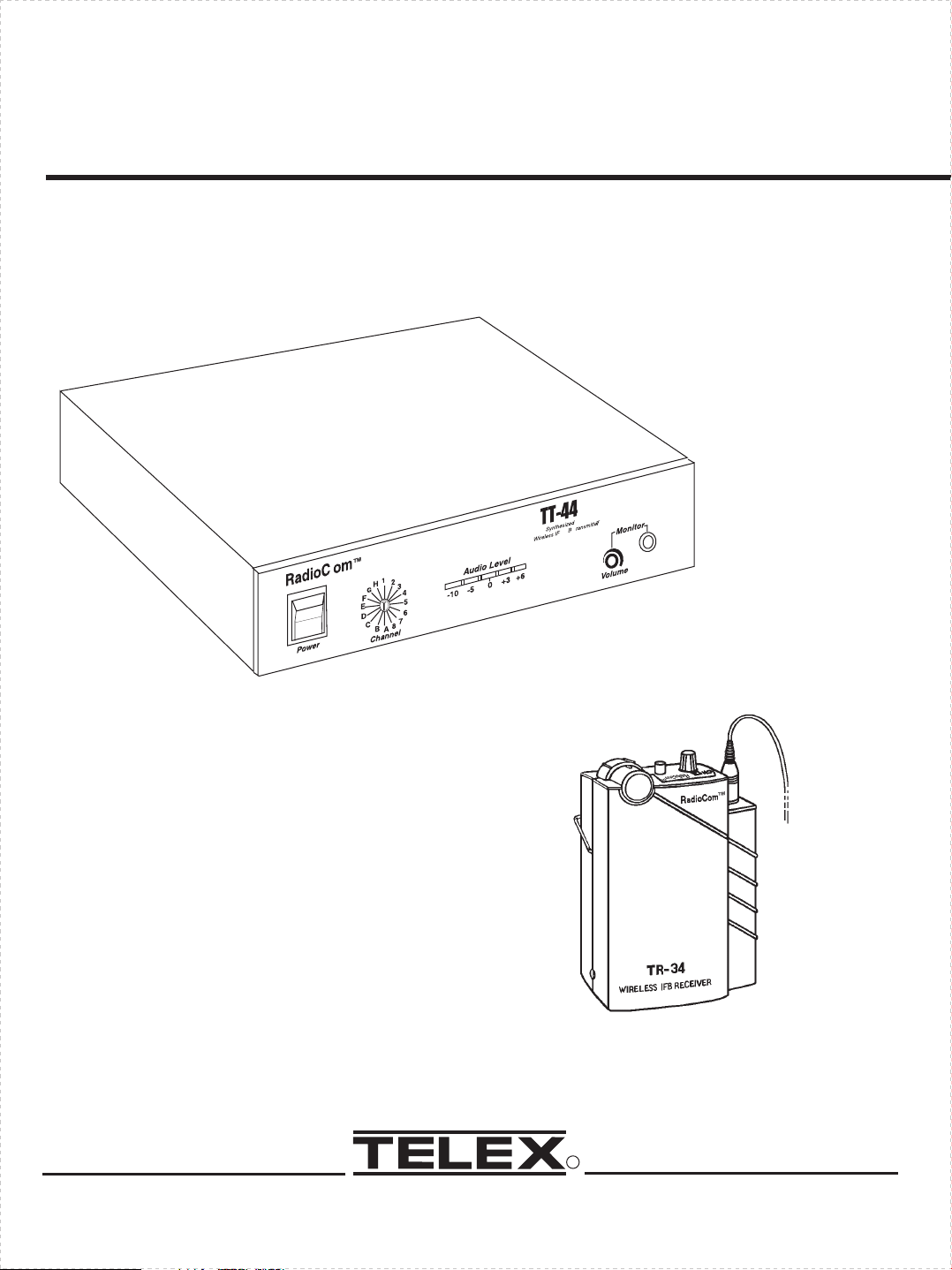
TR-34 TUNABLE RECEIVER
TT-44 TRANSMITTER
R
Page 2
PROFESSIONAL
WIRELESS IFB SYSTEM
INTRODUCTION
WHAT IS THE TELEX WIRELESS
IFB SYSTEM?
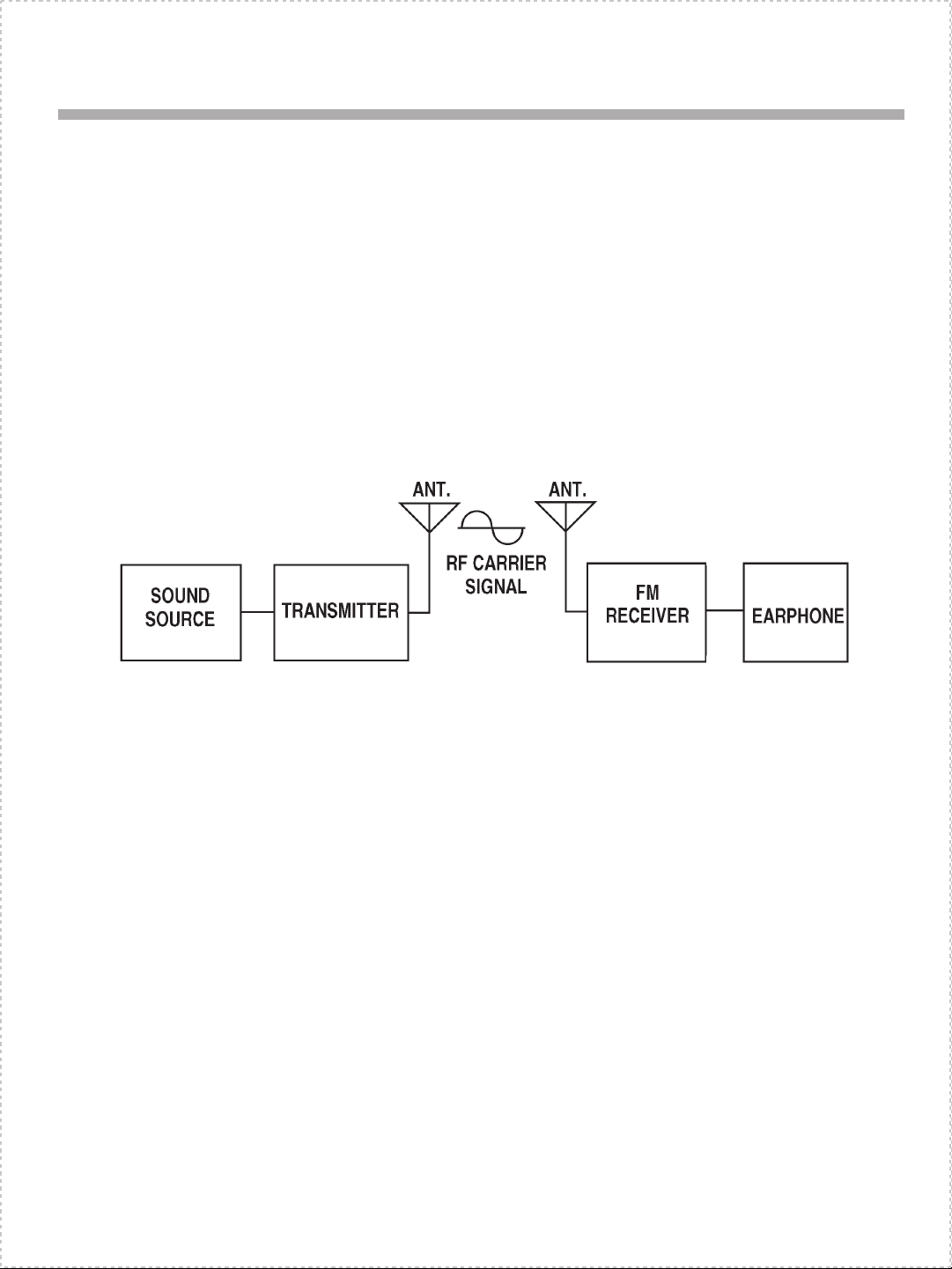
Transmitter: The transmitter generates and
amplifies an RF (Radio Frequency) carrier
signal, modulates this carrier with the microphone signal, and radiates the modulated RF
carrier.
WHAT FREQUENCY BAND DOES
THE TELEX SYSTEM OPERATE
IN?
The Telex Systems features a synthesized
transmitter and a synthesized receiver operating in the VHF Band between 60-72 MHz.
See Table 1 for standard frequencies available.
Figure 1
Block Diagram of Typical Wireless IFB System
Receiver: The FM VHF receiver is tuned to
the frequency of the transmitter. The receiver
picks up the radiated RF signal from the transmitter through the antenna and converts the
RF signal into audio voltages for use with an
earphone, headphone, button receiver,
neckloop, etc. The receiver frequency must be
matched to the transmitter frequency.
Up to five transmitter channels can be utilized
by any number of receivers in any given area.
-1-
Page 3

OFTEN ASKED QUESTIONS
Question: Can more than one system be
used simultaneously?
Answer: Yes but never on the same fre-
quency. You will need to have different frequencies for every receiver/transmitter
combination. All transmitters are factory set
for specific frequencies.
Question: Is the system more sensitive in
any one particular direction?
Answer: No, the transmitter’s antenna radi-
ates equally in all directions, but the signal is
attenuated by your body, walls or other surrounding objects. The receiving antenna is essentially sensitive in all directions as well.
Question: Can the receiver receive other
transmissions when the transmitter is turned
off?
Answer: Yes it can. Telex systems operate
in the VHF Band between 60-72 MHz. However, it is not susceptible to radio wave skip,
CB’ers or standard FM radio transmissions.
The frequency your system operates on is
computer selected for least interference, but
there is no such thing as a 100% clear channel
all the time, anywhere in the U.S.A., forever!
If the system is going to be used in a permanent fixed location, it should operate interference free until such a time or date when
someone else begins using the same frequency.
If the system is going to be moving among
various locations, you may run into occasional
frequency conflicts.
Whenever the system is in use, the transmitter
should be left on to prevent the receiver from
picking up outside interference.
-2-
Page 4

CHANNEL FREQ. in MHz
1 64.500
2 64.700
3 64.900
4 65.100
5 65.300
6 65.500
7 65.700
8 65.900
A 66.100
B 66.300
C 66.500
D 66.700
E 66.900
F 67.100
G 67.300
H 67.500
Table 1
Standard Frequencies Available
-3-
Page 5

TECHNICAL INFORMATION
TR-34 RECEIVER
General Description TR-34
The Telex TR-34 Receiver is a component of
a system which operates on 16 selectable
channels in the 60-72 MHz frequency band.
The receivers are designed to be used with the
Telex TT-44 Transmitter.
Operating Features
Volume OFF/ON Control: This thumbwheel
control serves as both an off/on switch and as
a volume control. The receiver is turned off
when the control is in the extreme counter-clockwise position, when viewed from the
front, and the volume is loudest when the control is in the extreme clockwise position as indicated on the volume control.
NOTE: The Headphone Jack must have a
headphone, or other accessory, plugged in
to activate the TR-34 power “ON”. Power
“ON” is indicated by the lighting of the
channel numbers.
Headphone Jack
The headphone jack accepts a 0.140-inch (3.5
mm) diameter miniature mono or stereo phone
plug. A variety of accessory units can be
plugged into this jack for reception of the desired channel(s) being transmitted.
Treble Control
A push button treble control is provided to enhance the “high” audio when the button is engaged, indicated by , the “High” audio is
emphasized.
Belt Clip
The belt clip supplied is detachable by spreading the wire apart at the tops and removing
one side of the clip from the case and then the
other.
-4-
Page 6
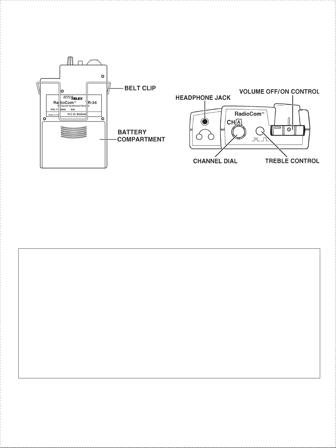
Figure 2
Operating Features of TR-34
TR-34 Specifications
Temperature Range....................................................................................0 to +50 degrees C
Supply Voltage ..........................................................................2 - 3 Volts, (2) AA Batteries
Battery Life...........................................................................................16 - 20 Hrs - Alkaline
8-10Hrs- Nickel-cadmium
Frequency Response 100-10 kHz ....................................................Less than 3 dB Variation
Sensitivity (12 dB SINAD @ 66.1 MHz)................................................................1 uV max
Distortion..............................................................................................................less than2%
Controls and Connections...............................................................Volume OFF/ON Switch,
Treble Control Switch,
Channel Selection Switch,
Headphone Output Jack
-5-
Page 7

TT-44 SYNTHESIZED
TRANSMITTER
General Description
The Telex TT-44 is a portable base station
transmitter which operates in the 60-72 MHz
band and accepts intercom audio input levels.
Operating Features
Main Power Switch and Indicator LED:
The Power “ON” LED is illuminated when
the Power OFF/ON switch is ON. It remains
illuminated while the transmitter is on.
Channel Select
This control is rotated in the clockwise and
counterclockwise directions to attain reception
of the desired channel(s) being transmitted
within the 60-72 MHz frequency band.
RF Power Switch: 50 mW max in “Hi”, approximately 5 mW in “Low”.
Audio Level Meter: Provides visual indication for setting input levels.
Audio “Monitor” Output Jack: 1/4" jack
provided for headset connection.
Audio “Monitor” Level Control: Adjusts
output level for monitor headset.
Balanced Audio Input Connector: Accepts
balanced two wire line or RTS two channel
line.
Balanced Input Selection Switch: Selects
either balanced two wire, RTS channel “1" or
RTS channel ”2".
Balanced Input Level Control: Adjusts input
level for all balanced input modes.
Unbalanced Audio Input Connector: Accepts unbalanced audio via 1/4" plug.
Unbalanced Audio Level Control: Adjusts
input level for unbalanced input mode.
Antenna Jack: Accepts 50-ohm whip (supplied).
RadioCom
TM
G
F
E
D
C
MAIN POWER SWITCH
Power Input Jack: Accepts either AC Power
adaptor (supplied), or any source of 13 VAC
300MA or 15 to 24 VDC 300MA.
AUDIO LEVEL METER
TT-44
Synthesized
H
+3
-5 0
-10
B
Wireless IFB Transmitter
+6
Figure 3
Operating Features TT-44
Front Panel
-6-
Page 8

BALANCED AUDIO
INPUT CONNECTOR
UNBALANCED
INPUT JACK
ANTENNA JACK
PUSH
Input-Intercom/IFB
RTS CH1
RTS CH2
AudioCom
RTS
CH
BALANCED INPUT
SELECTION SWITCH
BALANCED INPUT
LEVEL CONTROL
TelexCommunications, Inc. MADE IN U.S.A.
Unbalanced
Pin Out
Input
1-2
1-3
2-3
RTS CH2
1
Audiocom
Level
Audio Input
RF Power
Level
HI
LOW
Antenna
Power
15.24 VDS /13 VAC
RF POWER
SWITCH
POWER INPUT JACK
UNBALANCED INPUT
LEVEL CONTROL
Figure 4
Operating Features TT-44
Back Panel
TT-44 Specifications
Audio Input: Balanced Female XLR
Input Impedance.............................................................................................150K ohms
Unbalanced Audio Input ..............100K W input impedance/70 mV-7 Volt input range
RF Power Switch....................................50 mW max in “Hi”, approx. 5mW in “Low”
AGC Range .............................................................................................................30 dB
Signal-to-noise Ratio ..............................................................................................58 dB
Pre-Emphasis ..........................................................................................................100
Maximum Deviation ..........................................................................................
±25 KHz
Frequency Control Crystal.................................................................+/-.005% tolerance
Available Frequencies ......................................................................See Table 1, page 3
Max. Transmitter Output Power ..........................................................................50 mW
Power Requirements ............................13 VAC @ 300 mA or 15-24 VDC @ 300 mA
Dimensions .......................................................................7 1/2"W x 1 3/4"H x 6 7/8"D
FCC I.D. ..........................................................................................................B5DM507
-7-
mS
Page 9

TT-44 Transmitter
UNPACKING: Unpack your wireless IFB
system. If there are any damages or shortages,
refer to the “Warranty Service Information.”
TT-44 TRANSMITTER LOCATION: Select a suitable location for the TT-44 Transmitter. Try to keep a clear, unobstructed path
between the transmitter and receiver and allow plenty of free space around the Transmitter antenna.
CAUTION
Avoid heat sources when selecting a location for the Transmitter. The heat given off
by radiators or direct sunlight may eventually damage the unit.
POWER CONNECTION: Plug the supplied
AC power adaptor into a standard 120 vac
(U.S.A.) electrical outlet. Plug the other end
of the cord into the power input jack on the
rear panel of the TT-44 DO NOT TURN
UNIT ON AT THIS TIME.
ANTENNA CONNECTIONS: Connect the
telescoping whip antenna to the rear panel
ANTENNA jack.
For best results, the antenna should be vertically aligned. Tighten the coaxial connector to
hold the antenna in place, and extend the antenna to full length.
Figure 6
Antenna Connection
Figure 5
Connecting Power
-8-
Page 10

AUDIO INPUT: Select the appropriate input
on the rear panel switch depending on the interfacing equipment. Then connect the audio
input to the rear panel XLR Jack or to the unbalanced 1/4" input jack if required.
Figure 7
Balanced Input Jack, Switch, and
Level Control
Turn the input level control fully counterclockwise.
MULTIPLE SYSTEM
INSTALLATIONS: As with any radio de-
vice, interference can occur at any time. The
frequencies offered are shared with other legitimate users. The severity of interference
varies with the distance to the interfering station. Multiple systems further complicate installations. The following steps are suggested
in order to achieve best results in your installation.
1. In order to determine whether your selected
frequencies have minimum interference, Telex
recommends that you first temporarily install
the receivers only, in your proposed setting,
and monitor the channel for interference. To
do this, with fresh batteries installed, turn on
your receiver, but DO NOT turn on any other
receiver or transmitter at this time. Audible interference may be present, indicating another
user on the channel. Monitoring should be repeated for each channel that you propose to
use.
Unbalanced
Audio Input
Level
Figure 8
Unbalanced Input Jack and
Level Control
Turn the unbalanced control fully counterclockwise.
Refer to page 11, “Setting System Gain”, for
setting the optimum signal gain.
2. Next, you must decide on the placement of
the various channels. This is best accomplished by placing adjacent channel operating
areas as far apart as possible.
3. For best results, each transmitter should be
installed separately in its own service area.
The Transmitter should now be ready for use.
NOTE: When not in use, return the POWER
switch to the OFF position and unplug the
transmitter.
-9-
Page 11

EQUIPMENT OPERATION
TR-34 RECEIVER
Operation of the TR-34 Receiver
Try to keep a clear, unobstructed path between the transmitter and receiver antennas
for a clear transmission.
Plug in a unit such as an earphone, headphone
button receiver, induction coil neckloop, or
audio-input hearing aid into the receiver jack
(The cord acts as a receiving antenna).
BATTERY REPLACEMENT
The TR-34 Receiver uses two (2) AA batteries. When the batteries are low the sound will
be distorted. Replace weak batteries with two
fresh AA batteries, and position them in the
battery compartment as illustrated in Figure 9.
Rotate the VOLUME OFF/ON control slowly
in the clockwise direction while monitoring
the volume level, and select the correct receive channel.
Adjust volume for desired comfort. (Engage
treble control to enhance “Highs” if desired.)
When satisfied with the channel selection and
volume level, place the receiver in a pocket or
clip it to your belt for convenience.
Always return the VOLUME OFF/ON control
to the OFF position when the Receiver is not
in use to preserve battery life.
For additional information refer to the “Battery Information” Section.
NOTE: If the unit is to be stored for any
length of time make sure you remove the batteries from the unit.
Figure 9
Battery Installation - TR-34
-10-
Page 12

SETTING SYSTEM GAIN
If you have followed the instructions up to
this point you should now be ready to turn
both the transmitter and the receiver “ON”
and set optimum signal gain.
Place the power switch on the TT-44 Transmitter to the “ON” position. The red LED in
the power switch should now be lit. Turn your
microphone or other input equipment on and
the AUDIO LEVEL Meter will now respond
to your equipment.
Normal Level Setting: The balanced or unbalanced “Audio Gain” (Input Level Control)
will adjust the audio of the transmitter and for
normal readings this is in the green area between -10 and O. Readings in this area of the
meter give the highest dynamic range and no
overload.
High Level Setting: If your input equipment
has a high output, you will have to adjust the
Input Switch or Input Level Control to the
green area of the AUDIO LEVEL Meter or
you will overload the TT-44 indicated by one
or more red LED’s resulting in distortion.
Figure 10
Ideal Audio Level Meter Reading
Figure 11
High Level Setting
-11-
Page 13

TESTING THE SYSTEM
PRE WALK-THRU CHECKLIST
Following the instructions fully to this point
you have successfully completed the following checklist:
Located the Transmitter properly.
Connected power to the TT-44
Transmitter.
Connected the antenna to the TT-44
Transmitter.
Connected your Intercom to your
transmitter.
Installed the batteries in the TR-34
Set the Transmitter Audio Gain(s)
If you missed any of the above instructions,
go back and complete that instruction before
going on.
SYSTEM WALK-THRU
Now that you have successfully “set up” your
Telex Wireless System and turned on your
sound equipment, you are ready to test the
overall performance by “walking” the Telex
receiver through the areas in which you will
be using it.
The “system walk-thru” can detect the following problems:
Weak signal strength caused by:
·
Power Transmitter location
·
RF “Trouble Spots”
·
Operating distance beyond system
·
capability
· Malfunctioning system.
·
Mistuned Receiver
Under normal conditions the AUDIO LEVEL
Meter, located on the front panel of the
TT-44, should show a reading in the -10 to 0
(green) range with occasional +3 peaks (red).
Avoid +6 peaks as these will result in distorted audio at the receiver.
See “SETTING SYSTEM GAIN”.
-12-
Page 14

BATTERY INFORMATION
General
Improper battery selection, use, installation
and care are the cause of numerous wireless
system failures.
Alkaline Batteries
Alkaline batteries such as Mallory’s
DURACELL® or Eveready’s ENERGIZER®
provide the most reliable operation in wireless
transmitters and receivers. The use of low cost
carbon-zinc batteries is NOT RECOMMENDED.
ANTENNA INFORMATION
Antenna Alignment
Input-Intercom/IFB
Input
RTSCH1
RTSCH2
AudioCom
RTSCH2
RTS
1
CH
PinOut
1-2
1-3
2-3
Audiocom
TelexCommunications,Inc. MADEIN U.S.A.
Unbalanced
AudioInput
RFPower
Level
Level
Antenna
HI
LOW
15.24VDS/ 13 VAC
PUSH
Power
PUSH
DO
Input-Intercom/IFB
Input
RTSCH1
RTSCH2
AudioCom
RTSCH2
RTS
1
CH
PinOut
1-2
1-3
2-3
Audiocom
TelexCommunications,Inc. MADEIN U.S.A.
Unbalanced
AudioInput
RFPower
Level
Level
DON'T
Antenna
HI
LOW
Power
15.24VDS/ 13 VAC
Nickel-Cadmium Batteries
These batteries can save you money in the
long run, as they can be recharged, but they
can also cause disappointing wireless performance. If you want to use rechargeable
nickel-cadmium batteries you must select a
heavy duty nickel-cadmium.
*ENERGIZER® is a registered trademark of Union Carbide
Corporation
*DURACELL® is a registered trademark of Duracell Inc.
Antenna Placement
Proper antenna placement probably has the
most effect on your TELEX Wireless System’s overall performance. Following the suggestions that follow should result in “dropout
free” performance.
Keep the distance between the transmitter and
the receiver(s) as short as possible. The
greater the distance the weaker the signal.
Figure 12
Antenna Alignment
Do and Don’t
Figure 13
Distance Between Transmitter and Receiver
-13-
Page 15

Make sure the “signal path” between the
transmitter and receiver(s) is unobstructed.
You should always be able to visually locate
the antenna of the transmitter at all times.
DO NOT - Mount the transmitter on, or next
to, metal such as beams, walls with metal
studs, etc. This will “detune” the transmitter
antenna which can result in loss of signal at
the receiver.
SIGNAL REACHES ANTENNA AT FULL STRENGTH WITH
NO OBSTRUCTIONS.
Figure 14
Keeping Site Clear to Antenna
Attempting to operate the sound enhancement
system through or around walls, ceilings,
metal objects, etc., will reduce system range
and performance.
Figure 16
Transmitter Antenna Placement
SIGNAL REFLECTION OFF A METAL OBSTRUCTION CAUSES
REDUCED SIGNAL AND “MULTIPATH”
Figure 15
Operating Through Obstruction
-14-
Page 16

TROUBLESHOOTING
Reread the sections of this manual to make
sure you have completed system set-up properly.
PROBLEM
DISTORTION - System’s audio quality seems dis-
torted at medium to high input levels.
HISS - System seems to produce a “hiss which is
undesirable.
DROPOUTS - When moving around the area in
which you will be using the system there seem to
be locations where the signal “swooshes” or completely disappears.
INTERFERENCE - System picks up signals other
than wireless transmitter.
If you are unable to solve the problem, contact the dealer from whom you purchased the
system for assistance.
SOLUTION
Reduce audio gain on transmitter by adjusting the
gain controls as suggested on page 11.
Check the gain settings on the transmitter and the
volume control on the receiver. They may be too
low.
Make sure the antenna is connected and fully extended. Follow the location suggestions on pages 15
and 16 Change the location of the transmitter antenna or avoid the bad area with the receivers.
Make sure the Telex TT-44 is turned on - this will
usually eliminate the interference signal.
REDUCED DISTANCE - System doesn’t operate
as far as it once did. System doesn’t operate as well
as you think it should.
BATTERIES DON’T LAST
HUM - Audio System emits hum or Buzz thru
speakers and sound enhancement receiver.
If problem persist with the transmitter “ON”, try
changing to another channel.
Receiver Battery is possibly in need of replacement.
Transmitter antenna possibly located incorrectly.
Receiver not tuned properly.
If using “throw away” batteries make sure they are
alkaline. If using nickel-cadmium batteries make
sure they were fully charged when you are using
them and fully drained when you are done before
recharging them.
Locate Transmitter away from the audio equipment.
-15-
Page 17

CUSTOMER SERVICE INFORMATION
If your receiver or transmitter should need servicing under the warranty, please contact:
Customer Service Department
TELEX COMMUNICATIONS, INC.
8601 East Cornhusker Highway,
P.O. Box 5579,
Lincoln, Nebraska 68505-5579 U.S.A.
Phone: (402) 467-5321 or 465-7021
All claims of defect or shortage should be sent to the above address. When returning
items for service, you must provide date and proof of purchase, such as a copy of the
sales receipt, to establish warranty. A letter should be included outlining all symptoms
and claimed defects. Information on how the equipment was installed and used is very
helpful. Please include your phone number and return address in case our service technicians need to contact you.
Units that have been modified cannot be accepted for repair.
Include all information requested by the Service Center. Then pack the unit as follows:
Check the unit to see that all parts and screws are in place. Then wrap it in heavy paper
or put it in a plastic bag. If the original carton is not available, place the unit in a strong
carton that is at least six inches bigger in all three dimensions than the unit. Fill the carton equally around the unit with resilient packing material (shredded paper, foam, etc.).
Seal it with gummed paper tape, tie it with a strong cord, and ship it by prepaid express,
United Parcel Service or insured parcel post to the Telex Service Department.
It is very important that the shipment be well-packed and fully insured. Damage claims
must be settled between you and the carrier and this can delay repair and return of the
unit to you.
Telex reserves the right to make changes in design and improvement on its product without assuming any obligation to install the same on any of its products previously manufactured. Further Telex reserves the right to ship new and/or improved products which
are similar to the form, fit and function of products originally ordered.
-16-
Page 18

FCC INFORMATION
The Telex TT-44 Transmitter is authorized under part 74 of the FCC Regulations. The Telex
TR-34 Receiver is authorized under Part 15 of the FCC Regulations. Changes or modifications to this equipment could void the user’s authority to operate the equipment.
ACCESSORIES
Rack Mounting Kit
RM-S For mounting one TT-44 ................................................................71081-001
RM-D For mounting two TT-44’s ............................................................71081-002
Earphone (For TR-34))
(single) ......................................................................................................59840-005
Earphone (For TR-34)
(dual)..........................................................................................................59840-007
Headphone (For TR-34))
(lightweight)...............................................................................................59840-003
Headphone
(Full Cushion) ............................................................................................63510-021
Button Receiver
(8-ohm) ......................................................................................................63699-006
Button Receiver Cord
(30 inch).....................................................................................................35796-011
NL-4
Induction Coil Neckloop ...........................................................................71120-001
Antenna, Telescoping
For TT-44...................................................................................................877960-1
-17-
Page 19

R
TELEX COMMUNICATIONS, INC. 12000 Portland Ave. South, Burnsville, MN 55337 U.S.A.
PN 801564-1 April 2002 Made in U.S.A.
 Loading...