

Page 1

Telex
Op er ating In struc tions
RadioCom
™
BTR-1, TR-1
Pro fes sional
Wire less
In ter com Sys tem
Page 2

Ta ble of Con tents
Sec tion 1 In tro duc tion ..............................................1-1
Gen eral De scrip tion ..........................................................................1 -1
Sys tem Fea tures .............................................................................1-1
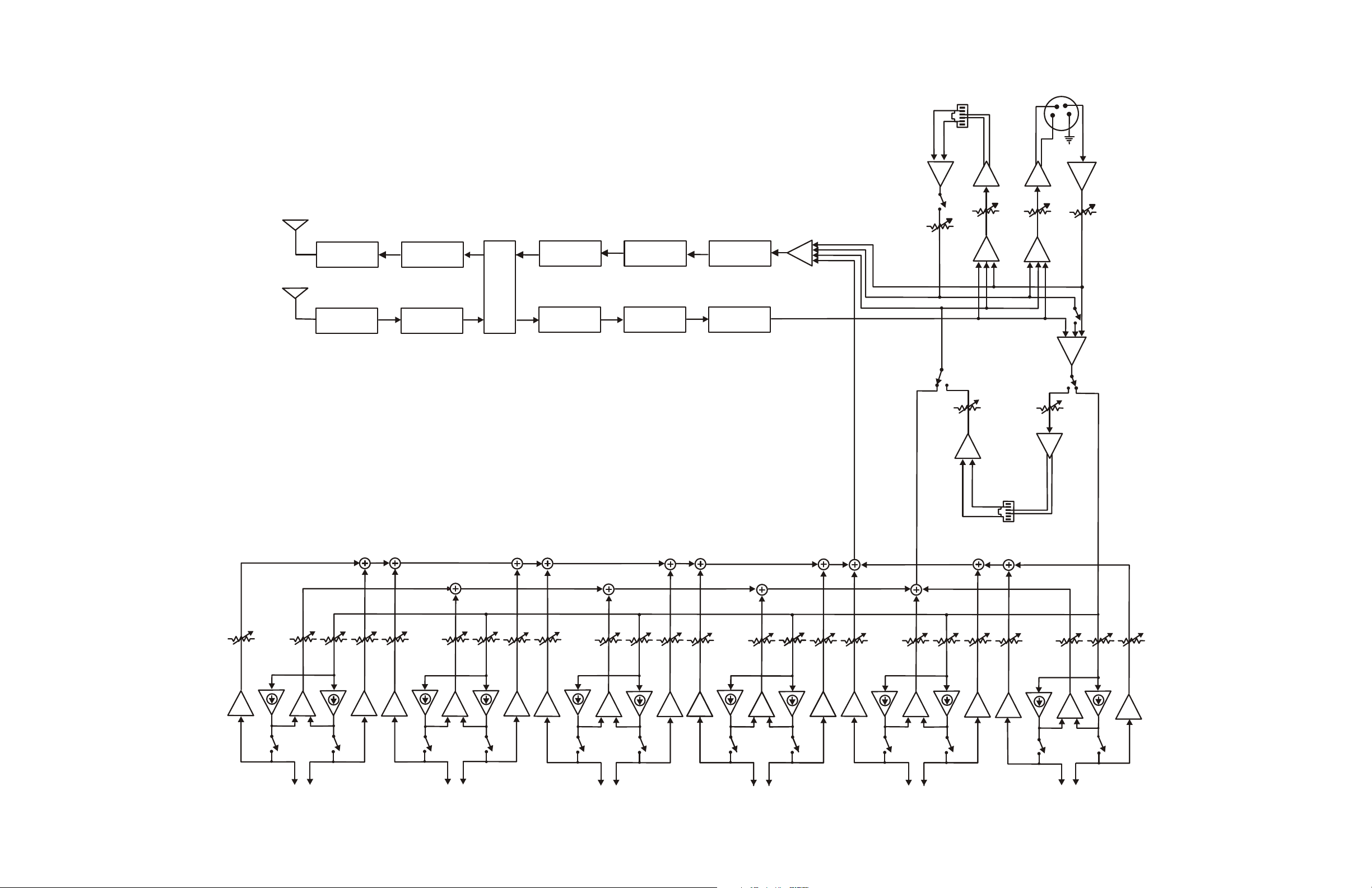
BTR-1 Block Di a gram........................................................................1-3
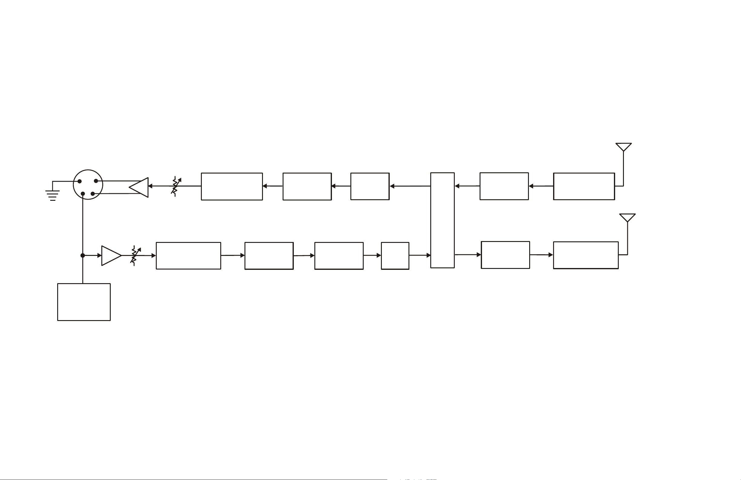
TR-1 Block Di a gram .........................................................................1-4
Sec tion 2 BTR-1 Base Sta tion ........................................2-1
Con trols and Con nec tions - Front Panel ..........................................................2-1
Con trols and Con nec tions - Rear Panel ...........................................................2-2
Sec tion 3 TR-1 Beltpack ............................................3-1
Con trols and Con nec tions - Top Panel............................................................3-1
Con trols and Con nec tions - Rear Panel ...........................................................3-2
Sec tion 4 Spec i fi ca tions .............................................4-1
BTR-1 Spec i fi ca tions.........................................................................4-1
TR-1 Spec i fi ca tions ..........................................................................4-2
Sec tion 5 Ini tial Equip ment Set-Up ...................................5-1
Un pack ing .................................................................................5-1
Rack Mount ing .............................................................................5-2
Rack Mount ing a Sin gle Base Sta tion ............................................................5-2
Rack Mount ing Two Base Sta tions Side-by-Side ...................................................5-2
An tenna Con nec tion .........................................................................5-3
An tenna Po lar iza tion .........................................................................5-3
Dis tance Be tween An tennas ...................................................................5-3
An tenna Place ment ..........................................................................5-3
Sec tion 6 BTR-1 Op er a tion..........................................6-1
Ba sic Op er a tional De scrip tion ..................................................................6-1
Sys tem Quick Start .......................................................................6-1
In ter fac ing to the BTR-1 ......................................................................6-3
TX/RX An ten nas ........................................................................6-3
2W In ter com Ports .......................................................................6-3
4W In ter com Ports .......................................................................6-4
Aux il iary Port ...........................................................................6-4
CAN Bus...............................................................................6-4
Re lay..................................................................................6-4
Lo cal Head set ...........................................................................6-5
Pow er ing the Base Station .....................................................................6-5
Start-up ...................................................................................6-5
Status Screen ...............................................................................6-5
En cryp tion Code ............................................................................6-6
Sys tem Set tings .............................................................................6-6
Name and Number .......................................................................6-6
Base Main Set tings .......................................................................6-6
In ter com Type ........................................................................6-7
Aux il iary Line ........................................................................6-7
Base TX Power .......................................................................6-7
Sidetone Lev els .......................................................................6-7
Fre quency Settings .......................................................................6-7
In ter com Set tings ............................................................................6-8
RF Me ter ..................................................................................6-9
ClearScanä ................................................................................6-9
Spe cial But ton Func tions .....................................................................6-10
-i-
Page 3

Ta ble of Con tents (con tin ued)
Sec tion 7 TR-1 Op er a tion ............................................7-1
Ba sic Op er a tional De scrip tion ..................................................................7-1
Sys tem Quick Start .......................................................................7-1
Bat tery Installation...........................................................................7-2
Trans mit Modes (PT TALK, PT TX).............................................................7-3
Head set Con nec tion ..........................................................................7-3
Sidetone ...................................................................................7-3
An tenna Con nec tions.........................................................................7-3
TR-1 Top Panel .............................................................................7-4
On/Off Vol ume Con trol ...................................................................7-4
BAT/O.M. Light .........................................................................7-4
Talk but ton .............................................................................7-4
A/B Selection Switch .....................................................................7-4
C Pushbut ton............................................................................7-4
Group and Chan nels .........................................................................7-5
Trans mit Fre quency ..........................................................................7-5
Re ceiver Fre quency ..........................................................................7-6
Bat tery Dis play .............................................................................7-6
Mi cro phone Gain ............................................................................7-7
Trans mit Power .............................................................................7-7
En cryp tion Code ............................................................................7-7
Se rial Num ber Code..........................................................................7-8
Auto Programing ............................................................................7-8
Soft ware/Chan nel Map Ver sion.................................................................7-8
ClearScan..................................................................................7-8
Lock Out ..................................................................................7-9
1st Use ....................................................................................7-9
Fac tory Re set ...............................................................................7-9
Sec tion 8 TR-1 Menu Struc ture ......................................8-1
Sec tion 9 BTR-1 Menu Struc ture .....................................9-1
Sec tion 10 Fre quency Bands ........................................10-1
Sec tion 11 Trou ble Shoot ing.........................................11-1
Sec tion 12 Bat tery In for ma tion ......................................12-1
Sec tion 13 2-Wire In ter com Spec i fi ca tions.............................13-1
Sec tion 14 FCC In for ma tion ........................................14-1
Sec tion 15 Soft ware Li cense.........................................15-1
Sec tion 16 Ac ces so ries and Re place ment Parts .........................16-1
-ii-
Page 4

Sec tion
1
In tro duc tion
Gen eral De scrip tion
The Telex RadioCom™ BTR-1 UHF wire less in ter com sys --
tems is the ul ti mate in re li able, high per for mance, en crypted
full du plex com mu ni ca tions.
The BTR-1 system in cludes the BTR-1 fre quency ag ile base
sta tion and a TR-1 fre quency ag ile beltpack. The BTR-1
system pro vides full du plex, en crypted digital com mu ni ca tion.
The base sta tion pro vides the beltpack with ac cess to a six in --
ter com port ma trix of 2-wire sys tems or com mu ni ca tion to a
4-wire in ter com sys tem. The sys tem can in ter face with
Audiocom® (Telex), RTS® TW, Clear-Com® 2-wire in ter --
com sys tems as well as 4 wire com mu ni ca tion sys tems.
In ad di tion to the 2 and 4-wire in ter com sys tems the base sta --
tion pro vides con nec tions for aux il iary bal anced au dio in put
and out put, as well as re lay clo sure and the abil ity for us ing
one of the six in ter com lines as a wire less only com mu ni ca tion
in ter com. The sys tem is also per fectly suited for stand-alone
op er a tion.
The BTR-1 has been de signed for re li able, ef fi cient op er a tion.
Op er ating in the 482 to 746 MHz range. The unit has ex --
pansion abil ity to add doz ens of base sta tions to cre ate a sys --
tem. The high-ef fi ciency beltpack pro vides up to 9 hours of
un in ter rupted op er a tion us ing stan dard al ka line bat ter ies.
Sys tem Fea tures
Fre quency ag ile base sta tion and beltpacks.
•
No ex ter nal com puter/de vice re quired to se lect fre quen -
•
cies.
Telex Com mu ni ca tions pro pri etary dig i tally en crypted
•
wire less com mu ni ca tion be tween the base sta tion and
beltpack.
AC or DC op er a tion in the 12 to15 Volt range.
•
Backlit base sta tion LCD al lows the user to eas ily mon i tor
•
the beltpack’s sta tus.
The fre quen cies of a beltpack may be changed at the
•
beltpack or from the base sta tion.
Beltpack units con tained in a weather and shock re sis tant
•
die cast mag ne sium case.
Six chan nels of 2-Wire in ter com.
•
Com pat i ble with Audiocom® (Telex), RTS TW,
•
Clear-Com®, RTS Ma trix and other wired in ter com types.
Re lay con tact clo sure on the base station that can be ac ti -
•
vated from the beltpack.
ClearScanä func tion to au to mat i cally find the best chan -
•
nels on which to op er ate.
Base sta tions are ta ble or rack mount able.
•
RTS® and Audiocom® are reg is tered trade marks of Telex Com mu ni ca tions, Inc.
Clear-Com® is a reg is tered trade mark of Clear-Com In ter com Sys tems, Inc.
1-1
Page 5

1-2 Blank
Page 6
LISTEN 1A
LISTEN 1B
LISTEN 2B
LISTEN 3A
LISTEN 3B
LISTEN 4A
LISTEN 4B
LISTEN 5A
LISTEN 6ALISTEN 5B
INPUT 1
OUTPUT 1
LISTEN 2A
OUTPUT 2
INPUT 4
OUTPUT 4
INPUT 3
OUTPUT 3
INPUT 5
OUTPUT 5
INTERCOM
PORT 1
INTERCOM
PORT 2
INTERCOM
PORT 3
INTERCOM
PORT 4
INTERCOM
PORT 5
INTERCOM
PORT 6
INPUT 6
4W
IN
4 WIRE
4W
OUT
2W
4W
4W
BTR-1 BLOCK DIAGRAM
HEADSET
GLOBAL/LOCAL
OUTPUT 6
LISTEN 6B
COMPRESSOR
EXPANDER
PRE
EMPHASIS
DE
EMPHASIS
A/D
LOW PASS
FILTER
TRANSMITTER
RECEIVER
SQUARING
AMP
DSP
D/A
AUX
IN
AUX
OUT
HS
LEVEL
MIC
GAIN
AUX
INPUT 2
2W
AUX IN
1-3
Fig ure 1-1
BTR-1 Block Diagram
Page 7
D/A
DSP
RECEIVER
TRANSMITTER
A/D
DE
EMPHASIS
EXPANDER
PRE
EMPHASIS
COMPRESSOR
SQUARING
AMP
LOW PASS
FILTER
RX
AUDIO
GATE
ELECTRET/
DYNAMIC
DETECT
TX
1
2 3
4
VOLUME
MIC
GAIN
Fig ure 1-2
TR-1 Block Diagram
1-4
Page 8
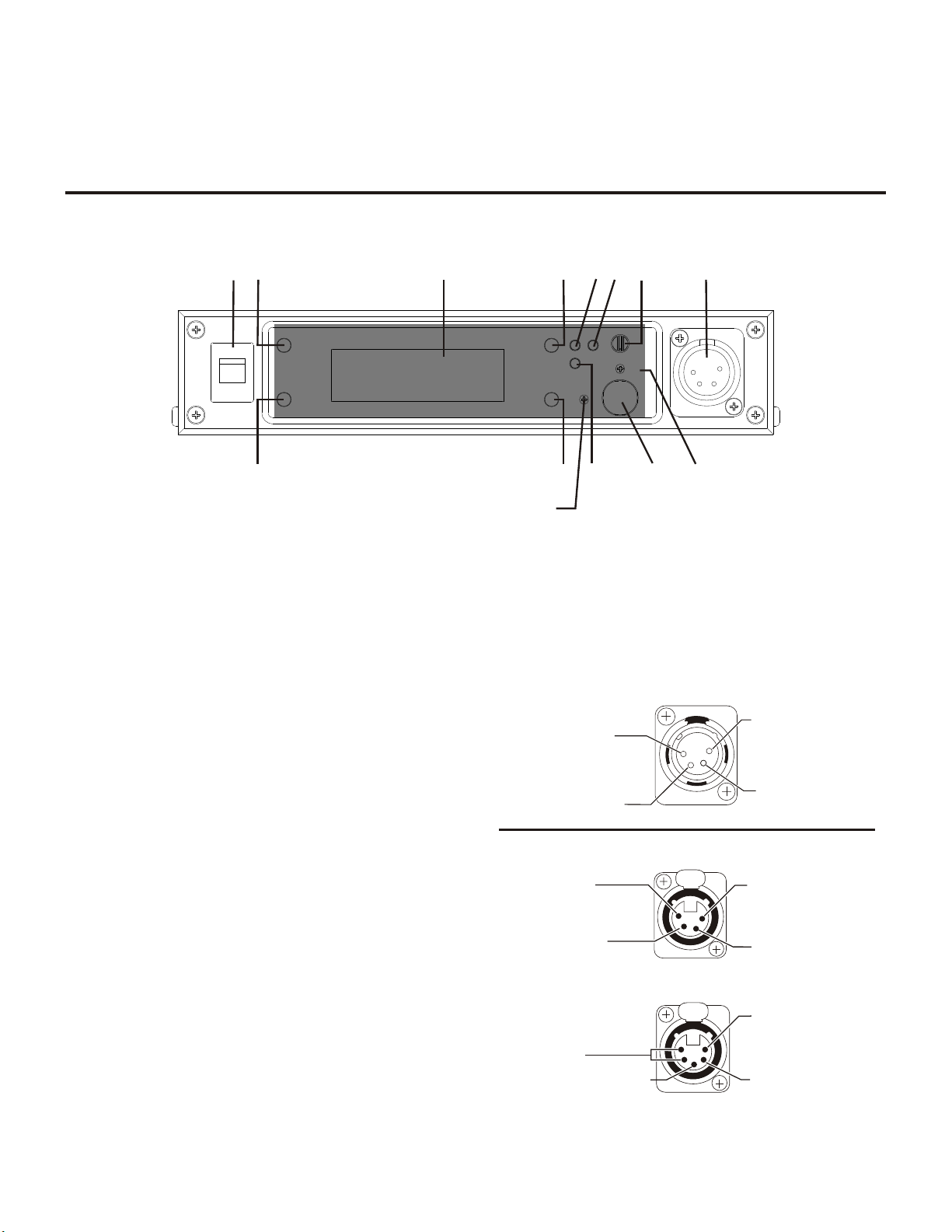
Con trols and Con nec tions - Front Panel
1 2 3 456
7
8
9
10
11
CONTRAST ADJUST
4
2
(1) Microphone
Shield
(2) Microphone
Audio
(3) Headphone
High (+)
(4) Headphone
Low (-)
(4) Headphone
Low (-)
(3) Headphone
High (+)
(1) Microphone
Shield
(2) Microphone
Audio
PUSH
(5) (4) Headphone
Low (-)
(3) Headphone
High (+)
(1) Microphone
Shield
(2) Microphone
Audio
PUSH
Sec tion
2
BTR-1 Base Sta tion
Fig ure 2-1
BTR-1 - Front Panel
1. On/Off Switch: Turns the base sta tion on/off
2. [Menu] and [Set] but tons: Used to se lect menus and set
op tions on the LCD.
3. Backlit LCD w/Con trast Ad just: Ad just the level of
con trast to the LCD.
4. [Up] and [Down] but tons: Used to se lect menus and set
op tions on the LCD.
5. Peak Aux Level Light: Will flash red when the aux il iary
in put level into the base sta tion is too high.
6. Peak In ter com Level Light: Will flash red when the in -
ter com in put lev els into the base sta tion are too high.
7.
Talk Light: Green when the talk but ton is ac tive. Will
turn red when the mi cro phone level into lo cal head set is
high.
11. Lo cal Head set Con nec tor: Male XLR con nec tor for
Telex units, Fe male XLR con nec tor for RTS units. A dy namic or electret head set mi cro phone is au to mat i cally de tected.
Telex Units
RTS Units
8. Talk But ton: Press to en able the au dio path from the
head set.
9.
Head set Vol ume: Used to ad just the vol ume level out to a
head phone.
10.
Mi cro phone Gain: Ad justs the au dio gain from the lo cal
head set mi cro phone.
2-1
Fig ure 2-2
Lo cal Head set Wiring
Page 9
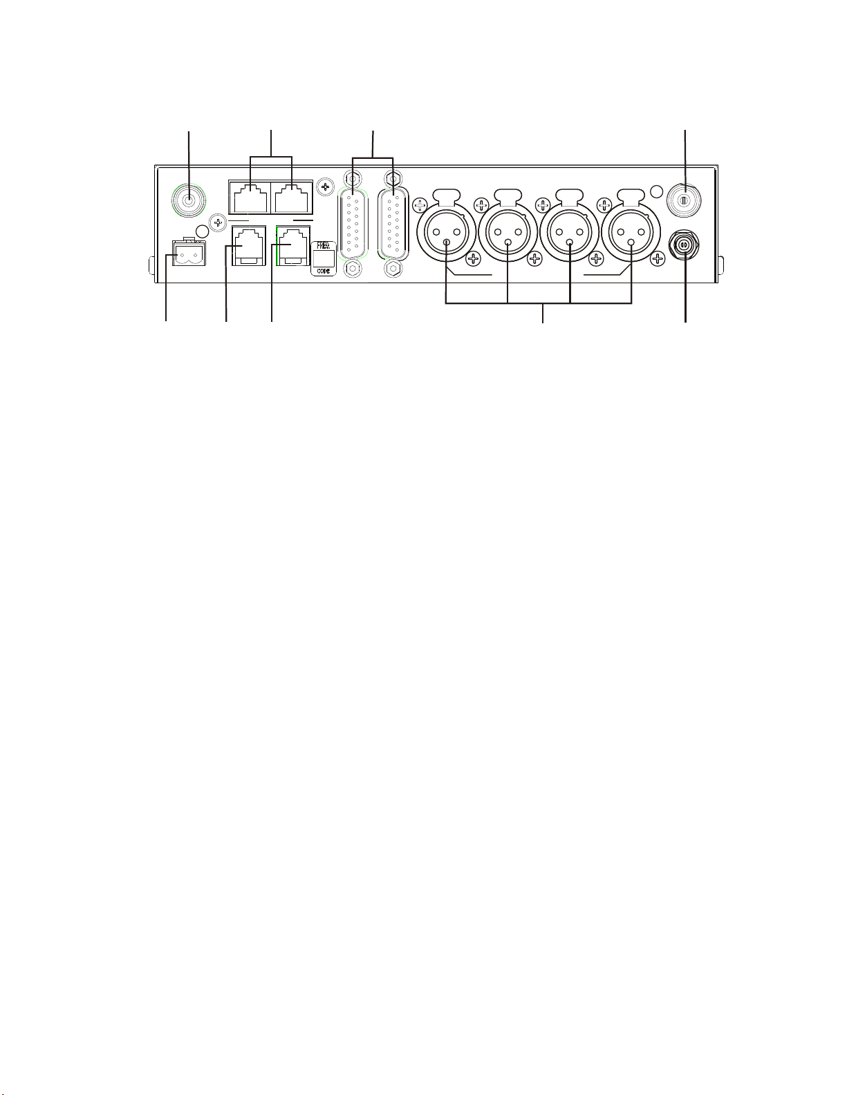
Con trols and Con nec tions - Rear Panel
ANT
CAN BUS
RCV
RELAY
AUX 4 WIRE
LOOP
THRU
Telex
TELEX COMMUNICATIONS, INC.
2 WIRE INTERCOM
1
2
3
4
TRAN
12-15V AC/DC
1 AMP
BTR-1
PATENT NO. 6,373,951 B1
MADE IN U.S.A.
13
15
17
20
12
14
16
18 19
ANT
BTR-1 - Rear Panel
Fig ure 2-3
12. Re lay Con tacts: Nor mally Open. When ac ti vated it will
close.
13. Re ceive An tenna Con nec tor: TNC Fe male con nec tor.
The color dot near the con nec tor must match the color of
the an tenna.
14. Aux il iary Connector: RJ-11 con nec tor used to con nect
balanced aux il iary au dio into and out of a base sta tion.
15. CAN Bus: RJ-45 con nec tors used to con nect a base sta tion to a CAN type of com mu ni ca tions bus.
16.
4 WIRE Con nec tor: RJ-11 con nec tor used to con nect
bal anced 4-W au dio into and out of the base sta tion.
17.
In ter com Loop Thru: Two DB15 con nec tors used to
loop 6 chan nels of in ter com au dio thru a base sta tion.
18.
In ter com Jacks: XLR in ter com jacks to al low in ter fac ing
to the first four in ter com ports via XLR con nec tors in ad di tion to them be ing avail able at the DB15 con nec tors.
19.
Power Con nec tor: In put power jack that re quires 12 to
15 Volts AC or DC at 1000 mA.
20.
Trans mit An tenna Con nec tor: TNC Fe male con nec tor.
The color dot near the con nec tor must match the color of
the an tenna.
2-2
Page 10
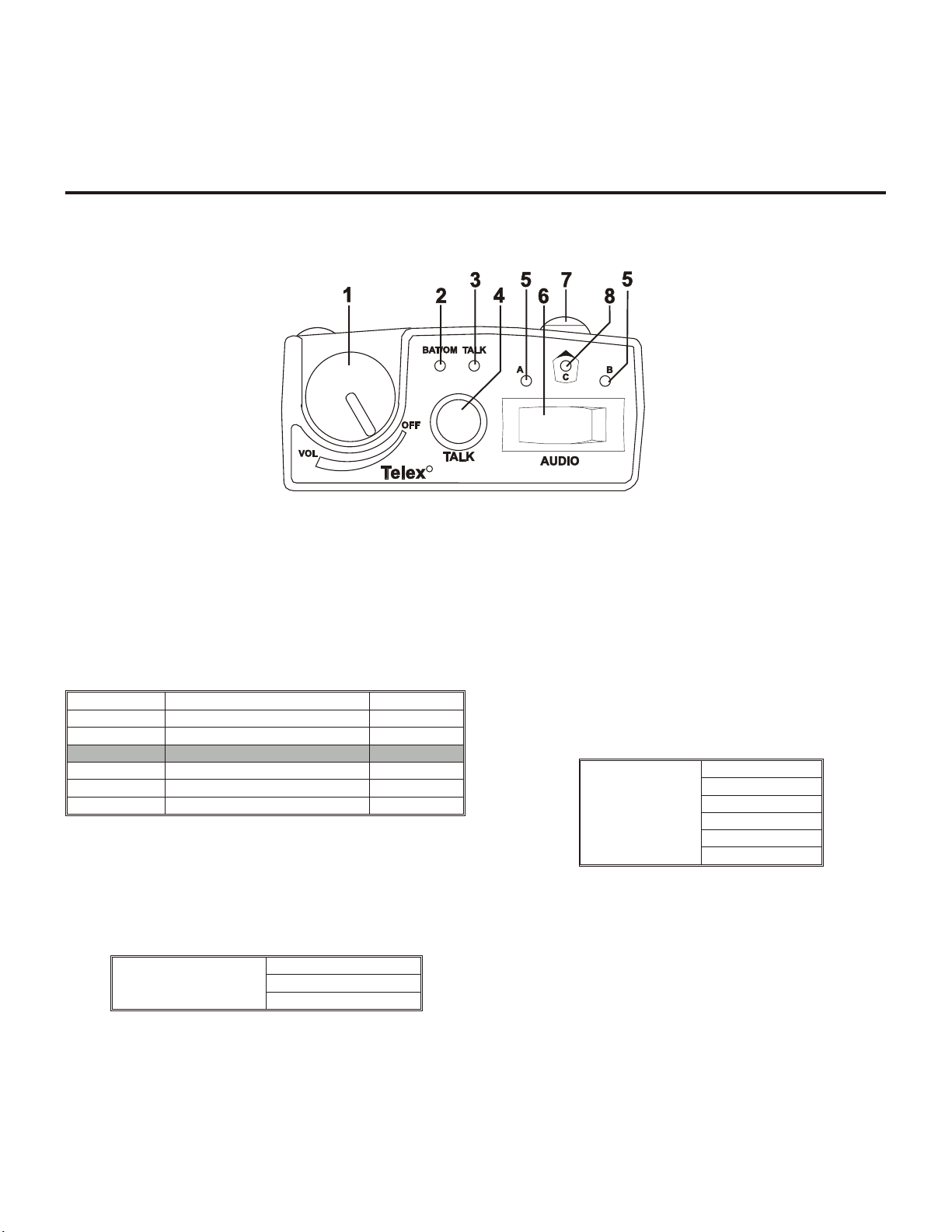
Con trols and Con nec tions - Top Panel
R
Sec tion
3
TR-1 Beltpack
Fig ure 3-1
TR-1 Top Panel
1. On/Off & Vol ume Con trol: Turns the beltpack power on
and con trols head set vol ume.
2.
BAT/O.M. Light:
Bat tery
Overmodulation
3. Talk Light: LED is on when the talk but ton is ac tive.
4. Talk but ton: Press to en able the au dio path from the
head set.
Selectable Modes:
TALK
Light flashes on power up = Bat tery OK
Light on continuously = Bat tery Low
Light does not flash or come on = Bat tery Dead
Light flashes on loud est speech = Gain OK
Light flashes on all speech = Gain too high
Light never flashes on loud est speech = Gain too Low
Push-to-Talk
Push-to-Latch
Off
5.
A and B Lights: "A" light is on if se lec tion switch in A
po si tion. "B" light is on if se lec tion switch in B position.
6.
Se lec tion Switch: Switches be tween base sta tion pre sets
A or B.
7.
"C" Pushbutton: Press to en able the base sta tion "C"
pre sets.
Momentary
Selectable Modes:
But ton "C"
8.
"C" But ton Light: "C" light is on if "C" pushbutton ac tive.
Latching
Quarterback
Off
Push-to-Talk
Latch ing Talk
3-1
Page 11

Con trols and Con nec tions - Rear Panel
(1) Microphone
Shield
(2) Microphone
Audio
(4) Headphone
Low (-)
(3) Headphone
High (+)
(1) Microphone
Shield
(4) Headphone
Low
(3) Headphone
High (+)
(2) Microphone
Audio (+)
13
15
14
MENU
SET
PT
TX
PT
TALK
10
9
11
12
(1) Microphone
Shield
(5) (4) Headphone
Low
(3) Headphone
High (+)
(2) Microphone
Audio (+)
Fig ure 3-2
TR-1 Rear Panel/Con nec tor/An ten nas
9. [MENU] and [SET] but tons: Used to se lect menus and
set op tions on the LCD.
10. LCD (Liq uid Crys tal Dis play)
11. [UP] and [DOWN] but tons: Used to se lect beltpack op -
tions on the LCD.
12. Push-to-Talk/Push-to-Transmit Switch:
Push-to-Talk (PT TALK): The trans mit ter is al ways
on. No au dio is sent un less the talk but ton is ac tive.
Rec om mended po si tion.
Push-to-Trans mit (PT TX): The trans mit ter and au dio paths are off ex cept when the talk but ton is ac tive.
13. Head set Con nec tor: Male XLR con nec tor for Telex
units, Fe male XLR con nec tor for RTS units.
14. Bat tery Latch: Press down to en able the bat tery pack to
be re leased. While the latch is held down, slide the bat tery
pack about 1/8 inch back, to ward the latch, un til it stops,
then lift out.
15. Re ceive and Trans mit An tennas: The an ten nas are screw
type, ¼ wave, re place able an ten nas. The color dot on the
screw end of the an tenna must match color dot on an tenna
re cep ta cle.
3-2
Fig ure 3-3
Head set Jack Wir ing
Telex Units
RTS Units
Page 12

Sec tion
Spec i fi ca tions
BTR-1
Spec i fi ca tions
Over all
RF Fre quency Range ..................................482 - 608 MHz, 614 - 746 MHz in 18 MHz TX and RX bands
Power Re quire ments ............................................................12-15 Volts AC/DC @ 1 Amp
Tem per a ture Range...........................................................-4° F to 130° F (-20° C to 55° C)
Di men sions............................................8.25” W x 1.72” H x 9.00” D (20.9 cm x 4.4 cm x 22.9 cm)
Weight ...............................................................................3 lbs 8 oz (1.59 kg)
TX An tenna .........................................................½ Wave (sup plied), TNC Male Con nec tor
RX An tenna .........................................................½ Wave (sup plied), TNC Male Con nec tor
FCC ID: .....................................................................................B5DM519
Fre quency Re sponse ........................................................................100Hz-4.0kHz
Four Wire In put ............................................................Level Ad just able (2 Vrm s typ i cal)
Four Wire Out put ...........................................................Level Ad just able (2 Vrms typ i cal)
Telex In ter com................................In put/Out put Level Ad just able (1 Vrms typ i cal), Line im ped ance 300W
RTS In ter com .............................In put/Out put Level Ad just able (0.775 Vrms typ i cal), Line Im ped ance 200W
ClearCom® In ter com .......................... In put/Out put Level Ad just able (1 Vrm s typ i cal), Line Im ped ance 200W
Aux il iary In put .............................................................Level Ad just able (2 Vrm s typ i cal)
Aux il iary Out put ...................................................Level Ad just able (2 Vrms typ i cal into 600W)
Mi cro phone in put sen si tiv ity ............................................................10mV (200W Source)
Lo cal Head set Out put .................................................200mW out put into 150W (1% Dis tor tion)
Mute of Wire In come Port....................................................100 dB (30kHz Low Pass Fil tered)
4
Trans mit ter
Type ..................................................................Syn the sized Trans mit ter, 720 chan nels
Trans mit Power ...................................................50mW typical (High), 5 mW typical (Nor mal)
Mod u la tion Type .................................................................................GMSK
De vi a tion.......................................................................Com plies with FCC 74.861
RF Fre quency Sta bil ity............................................................................0.005%
Ra di ated Har mon ics & Spu ri ous ....................................................Ex ceeds FCC spec i fi ca tions
Re ceiver
Type .....................................................Dual Con ver sion Super het ero dyne, 720 chan nels each
RF Sen si tiv ity....................................................................<0.8 µV for 12 dB SINAD
IF Se lec tiv ity ............................................................................3 dB at 230 kHz
Im age Re jec tion ...........................................................................70 dB or better
RF Fre quency Sta bil ity............................................................................0.005%
Dis tor tion ..............................................................................<1% at peak level
S/N Ra tio out to wired In ter com Ports ...........................................80 dB (30kHz Low Pass Fil tered)
4-1
Page 13

TR-1
Spec i fi ca tions
RF Fre quency Range .......................482 - 608 MHz, 614-746 MHz in 18 MHz TX and RX bands
Power Re quire ments ........................................6 “AA” Cells Al ka line (NiMH op tional)
Cur rent Draw ...................................................190 mA (Push-to-Talk, Talk On)
Tem per a ture Range ..............................................-4° F to 130° F (-20° C to 55° C)
Di men sions .................................3.75”W x 5.10”H x 1.65” D (9.5 cm x 12.9 cm x 4.2 cm)
Weight ......................................................15 oz (425g) with al ka line batteries
TX An tenna..........................................1/4 Wave (sup plied), Screw type, Replaceable
RX An tenna..........................................1/4 Wave (sup plied), Screw type, Replaceable
FCC ID: .........................................................................B5DM520
Fre quency Re sponse ............................................................100Hz-4.0kHz
Mi cro phone in put sen si tiv ity.................................................7 mV (200W Source)
Lo cal Head set Out put .....................................200 mW out put into 150W (1% dis tor tion)
Trans mit ter
Type ...............................................................Syn the sized, 720 chan nels
Trans mit Power ....................50 mW typ i cal (High), 5 mW typ i cal (Low), or auto-power switching
Mod u la tion Type .....................................................................GMSK
De vi a tion...........................................................Com plies with FCC 74.861
RF Fre quency Sta bil ity ................................................................0.005%
Ra di ated Har monics & Spu ri ous .................................Meets or ex ceeds FCC spec i fi ca tions
Re ceiver
Type ..................................Dual Con ver sion Super het ero dyne, Syn the sized, 720 chan nels
RF Sen si tiv ity........................................................<0.8 µV for 12 dB SINAD
IF Se lec tiv ity.................................................................3 dB at 230 kHz
Im age Re jec tion ...............................................................70 dB or better
RF Fre quency Sta bil ity ................................................................0.005%
Dis tor tion ..................................................................<1% at peak level
S/N Ra tio in From wired In ter com Ports .......................................80 dB (30kHz Low Pass Fil tered)
4-2
Page 14

Un pack ing
Un pack your RadioCom™ sys tem. Be low are the items that
should come with your base sta tion and each belt pack. Con --
tact the ship per or your dealer im me di ately if any thing is dam --
aged or miss ing.
BTR-1
Quantity Description
1 BTR-1 Base Station
1 Operating Instructions
1 In-Line Power Supply
2 Antennas (one Transmit, one Receive)
Sec tion
5
Ini tial Equip ment Set-Up
TR-1
1 Limited Warranty Sheet
4 Rubber Feet
1 Gain Adjust Plastic Screwdriver
1 Two Terminal Plug (for Relay)
2 Large Phillips Pan head Screw for Rack Mounting
2 Small Phillips Flathead Screw for rack Mounting
1 Single Unit Rack Mount Bracket
1 Dual Units (Side by Side) Middle Rack Mount Bracket
1 Rack Mount Side Bracket
1 Interconnect Cable (15 pin to 15 pin)
Quantity Description
1 TR-1 Beltpack with Antennas
1 Instruction Card
1 Battery Pack
1 Limited Warranty Sheet
5-1
Page 15
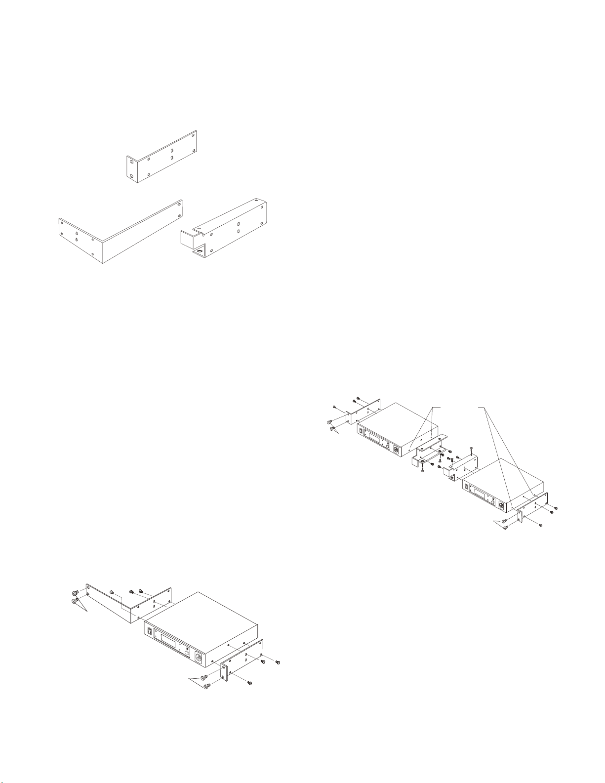
Rack Mount ing
SINGLE UNIT RACK MOUNT BRACKET
DOUBLE UNIT RACK MOUNT BRACKET
RACK MOUNT MIDDLE BRACKET
NOT
SUPPLIED
NOT
SUPPLIED
REMOVE SCREWS
(TYPICAL 4 SIDES)
NOT
SUPPLIED
NOT
SUPPLIED
The rack mount ing brack ets come with each BTR-1. These
brack ets may be used to mount a sin gle base sta tion in a 19"
wide rack or mount two base sta tions side by side in a rack.
Fig ure 5-1 shows the three brack ets that come with a base sta --
tion.
Rack Mount ing Two Base Sta tions
Side-by-Side
1. Re move the four pan head screws (two on each side)
closes to the front panel.
2. Place the dou ble unit side brack ets on the sides of the base
sta tions you wish clos est to the edge of the rack.
3. Re place the two pan head screws and use a third pan head
screw (2 sup plied with base sta tion) to screw into the up per mid dle lo ca tion of the rack mount middle bracket.
4. Place the dual bracket on the other sides of the base sta tions. Make sure the bracket is flipped so the front bend is
to ward the front of the base sta tion. As you face the rack,
the right base station will have the mid dle bracket front
bend high and left base station will have the bend low.
5. Re place the two pan head screws and the other pan head
screw into the up per mid dle hole of each bracket.
Fig ure 5-1
Rack Mount Brack ets
Rack Mount ing a Sin gle Base Sta tion
1. Re move the four pan head screws (two on each side) clos est to the front panel.
2. Place the dou ble unit side bracket on the side of the base
sta tion you wish clos est to the edge of the rack.
3. Re place the two pan head screws and use a third pan head
screw (2 sup plied with base station) to screw into the up per mid dle lo ca tion of the bracket.
4. Place the sin gle unit rack mount bracket on the other side
of the base sta tion.
5. Re place the two pan head screws and the other pan head
screw that came with the base to se cure the bracket. Screw
the third screw into the up per mid dle hole of the bracket.
6. Use the rack mount screws (not sup plied) to se cure the
unit to the rack.
6. Use the four flat head screws (2 sup plied with base sta tion) to se cure the top and bot tom of the mid dle brack ets
to gether.
7. Use rack mount screws (not sup plied) to se cure the unit to
the rack.
Fig ure 5-3
Rack Mount ing Two Base Units Side-by-Side
Rack Mounting of a Sin gle Unit
Fig ure 5-2
5-2
Page 16
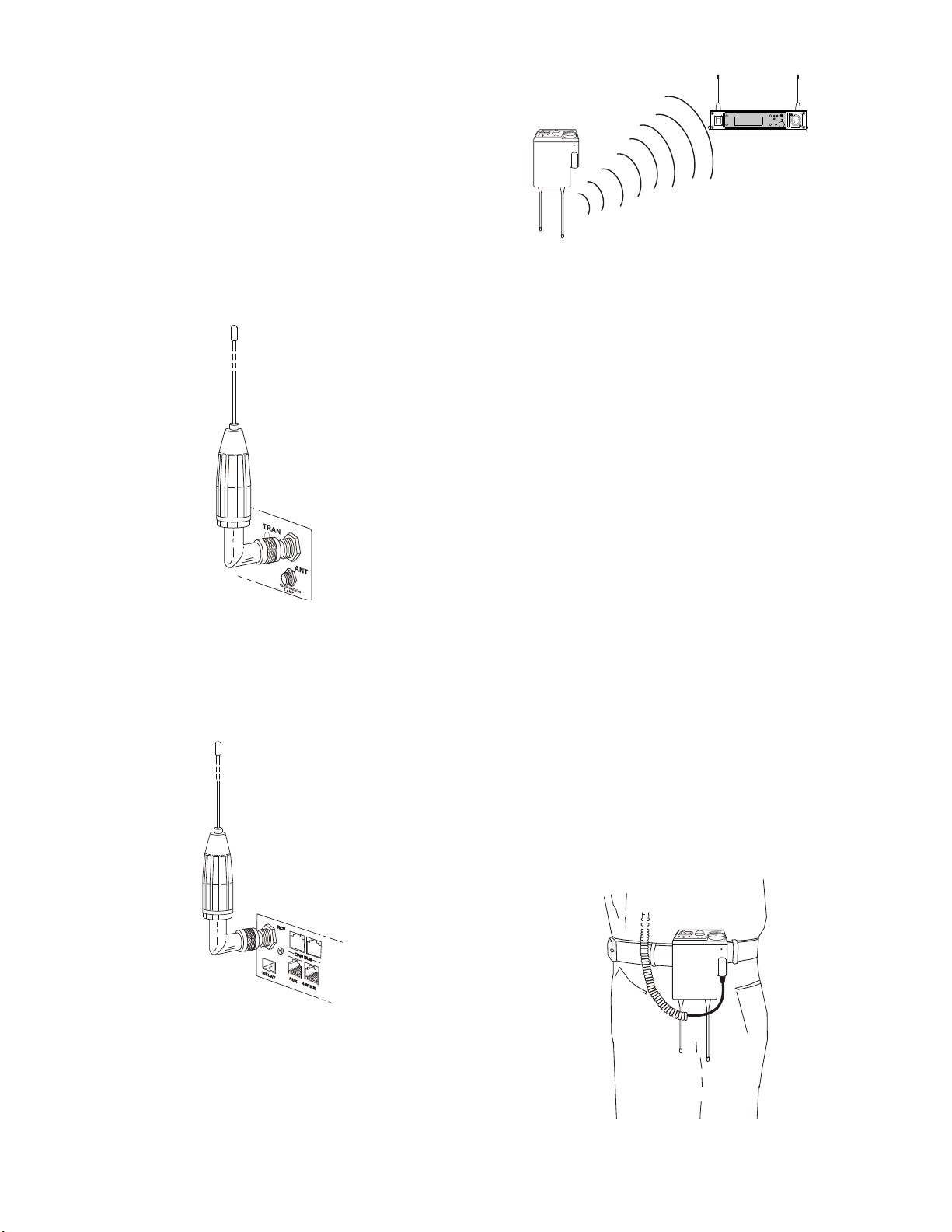
An tenna Con nec tion
O
F
F
B
A
T
/
O
M
T
A
L
K
R
a
d
i
o
C
o
m
T
R
-
1
T
M
VOL
Telex
T
e
l
e
x
A
O
F
F
B
A
T
/
O
M
T
A
L
K
R
a
d
i
o
C
o
m
T
R
-
1
T
M
VOL
Telex
T
e
l
e
x
A
The base sta tion is sup plied with two (2) an ten nas. One
1/2-wave an tenna for Trans mit and one 1/2-wave for Re ceive.
The an ten nas have TNC male con nec tors.
The fre quency range of the an ten nas should match the re ceiver
and trans mit ter of the base sta tion. Match the color code on
the an tenna with the color code on the base sta tion.
ANTENNAS SHOULD BE VERTICAL
At tach the transmit 1/2-wave an tenna to the an tenna in put re --
cep ta cle la beled “TRAN” on the right side of the rear panel.
The an tenna should be ver ti cally aligned.
Fig ure 5-4
Attaching Trans mit 1/2-Wave An tenna
At tach the receive 1/2-wave an tenna to the an tenna in put re --
cep ta cle la beled “RCV” on the left side of the rear panel. The
an tenna should be ver ti cally aligned.
Fig ure 5-6
Ver ti cally Po lar ized An tennas
Dis tance be tween An tennas
The dis tance be tween the base sta tion’s re ceive and trans mit
an ten nas is not ad just able when the an ten nas are con nected di --
rectly on the back of the unit.
The an ten nas can be remoted for better sig nal path. A Telex
coax as sem bly with re mote an ten nas may be re quired. See
“Ac ces sory and Re place ment Parts” sec tion for or der ing in for --
ma tion.
NOTE: If your base sta tion is to be lo cated in a shielded rack
mount en clo sure or other poor RF lo ca tion, you must re mote
the 1/2-wave an ten nas with coax as sem blies. See “Ac ces sories
and Re place ment Parts” sec tion for remote mount ing hard --
ware.
An tenna Place ment
Proper an tenna place ment prob a bly has the most ef fect on
your TELEX Wire less In ter com Sys tem’s over all per for --
mance. The fol low ing sug ges tions will re sult in op ti mum per --
for mance.
Fig ure 5-5
Attaching Receive 1/2-Wave An tenna
An tenna Po lar iza tion
The Telex Wire less In ter com Sys tem is “Ver ti cally Po lar ized”.
This means both the trans mit ting and re ceiv ing an ten nas
should op er ate in the ver ti cal po si tion.
Proper place ment of the beltpack can be crit i cal. The an ten nas
should be in the open. Bending the an ten nas up and plac ing
the beltpack in a pocket, etc., will re duce sys tem dis tance.
It is sug gested that the unit be worn on the belt or pocket with
both an tenna’s ver ti cal for best op er at ing range and per for --
mance.
Fig ure 5-7
Proper Dress ing of the An tennas
5-3
Page 17
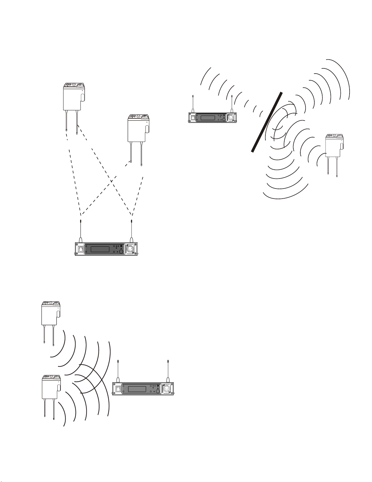
Keep the dis tance be tween the base sta tion and the beltpacks
700 FEET
100 FEET
O
F
F
B
A
T
/
O
M
T
A
L
K
R
a
d
i
o
C
o
m
T
R
-
1
T
M
VOL
Telex
T
e
l
e
x
A
O
F
F
B
A
T
/
O
M
T
A
L
K
R
a
d
i
o
C
o
m
T
R
-
1
T
M
VOL
Telex
T
e
l
e
x
A
O
F
F
B
A
T
/
O
M
T
A
L
K
R
a
d
i
o
C
o
m
T
R
-
1
T
M
VOL
Telex
T
e
l
e
x
A
O
F
F
B
A
T
/
O
M
T
A
L
K
R
a
d
i
o
C
o
m
T
R
-
1
T
M
VOL
Telex
T
e
l
e
x
A
O
F
F
B
A
T
/
O
M
T
A
L
K
R
a
d
i
o
C
o
m
T
R
-
1
T
M
VOL
Telex
T
e
l
e
x
A
as short as pos si ble. The greater the dis tance, the weaker the
sig nal. Make sure the “sig nal paths” be tween the base sta tion
and beltpacks are un ob structed. You should be able to vis i bly
lo cate the base sta tion an ten nas at all times for best per for --
mance.
At tempting to op er ate the wire less in ter com sys tem through or
around walls, ceil ings, metal ob jects, etc. will re duce sys tem
range and per for mance.
Fig ure 5-8
Dis tance Be tween base sta tion and beltpack
Fig ure 5-10
Op er ating Sys tem Near Obstructions
DO NOT - mount the base sta tion 1/2-wave an ten nas on, or
next to metal, such as beams, walls with metal studs, equip --
ment racks, etc. This also ap plies to the an ten nas when as sem --
bled di rectly to the Base Sta tion. This will “de tune” the
an ten nas which can re sult in noise or loss of RF sig nal at the
base sta tion.
Keep ing the dis tance from the base sta tion and beltpack as
short, and un ob structed as pos si ble will pro duce the most re li --
able per for mance.
The base sta tion is sup plied with two an ten nas. This should
pro vide sat is fac tory sys tem per for mance in most ap pli ca tions.
Sys tem range can be en hanced by remoting the 1/2-wave an --
ten nas.
Fig ure 5-9
Keeping Site Clear to An tennas
5-4
Page 18

CH 1
CH 2
1
2
3
4
5
6
1
2
3
4
5
6
CH 1
CH 2
CH 1
CH 2
CH 1
CH 2
CH 1
CH 2
CH 1
CH 2
CH 1
CH 2
CH 1
CH 2
CH 1
CH 2
CH 1
CH 2
CH 1
CH 2
CH 1
CH 2
RadioCom
IC-100
1 2
3
4
5
6
7
8 9
10
11 12
LINE 1 LINE 2
LINE 3 LINE 4 LINE 5 LINE 6
Telexâ
1
2
3
4
5
6
1
2
3
4
5
6
1
2
3
4
5
6
1
2
3
4
5
6
1
2
3
4
5
6
1
2
3
4
5
6
1
2
3
4
5
6
1
2
3
4
5
6
1
2
3
4
5
6
1
2
3
4
5
6
1
2
3
4
5
6
1
2
3
4
5
6
1
2
3
4
5
6
1
2
3
4
5
6
1
2
3
4
5
6
1
2
3
4
5
6
1
2
3
4
5
6
1
2
3
4
5
6
1
2
3
4
5
6
1
2
3
4
5
6
1
2
3
4
5
6
1
2
3
4
5
6
1
2
3
4
5
6
1
2
3
4
5
6
NEUTRIK NEUTRIK
NEUTRIK NEUTRIK
NEUTRIK NEUTRIK
NEUTRIK NEUTRIK
NEUTRIK NEUTRIK
NEUTRIK NEUTRIK
RadioCom
by Telex
ACS-101
UHF Antenna Splitter/Combiner
POWER - GREEN
OVERHEAT - RED
CH 1
CH 2
1
2
3
4
5
6
1
2
3
4
5
6
CH 1
CH 2
CH 1
CH 2
CH 1
CH 2
CH 1
CH 2
CH 1
CH 2
CH 1
CH 2
CH 1
CH 2
CH 1
CH 2
CH 1
CH 2
CH 1
CH 2
CH 1
CH 2
RadioCom
IC-100
1 2
3
4
5
6
7
8 9
10
11 12
LINE 1 LINE 2
LINE 3 LINE 4 LINE 5 LINE 6
Telexâ
1
2
3
4
5
6
1
2
3
4
5
6
1
2
3
4
5
6
1
2
3
4
5
6
1
2
3
4
5
6
1
2
3
4
5
6
1
2
3
4
5
6
1
2
3
4
5
6
1
2
3
4
5
6
1
2
3
4
5
6
1
2
3
4
5
6
1
2
3
4
5
6
1
2
3
4
5
6
1
2
3
4
5
6
1
2
3
4
5
6
1
2
3
4
5
6
1
2
3
4
5
6
1
2
3
4
5
6
1
2
3
4
5
6
1
2
3
4
5
6
1
2
3
4
5
6
1
2
3
4
5
6
1
2
3
4
5
6
1
2
3
4
5
6
NEUTRIK NEUTRIK
NEUTRIK NEUTRIK
NEUTRIK NEUTRIK
NEUTRIK NEUTRIK
NEUTRIK NEUTRIK
NEUTRIK NEUTRIK
CH 1
CH 2
1
2
3
4
5
6
1
2
3
4
5
6
CH 1
CH 2
CH 1
CH 2
CH 1
CH 2
CH 1
CH 2
CH 1
CH 2
CH 1
CH 2
CH 1
CH 2
CH 1
CH 2
CH 1
CH 2
CH 1
CH 2
CH 1
CH 2
RadioCom
IC-100
1 2
3
4
5
6
7
8 9
10
11 12
LINE 1 LINE 2
LINE 3 LINE 4 LINE 5 LINE 6
Telexâ
1
2
3
4
5
6
1
2
3
4
5
6
1
2
3
4
5
6
1
2
3
4
5
6
1
2
3
4
5
6
1
2
3
4
5
6
1
2
3
4
5
6
1
2
3
4
5
6
1
2
3
4
5
6
1
2
3
4
5
6
1
2
3
4
5
6
1
2
3
4
5
6
1
2
3
4
5
6
1
2
3
4
5
6
1
2
3
4
5
6
1
2
3
4
5
6
1
2
3
4
5
6
1
2
3
4
5
6
1
2
3
4
5
6
1
2
3
4
5
6
1
2
3
4
5
6
1
2
3
4
5
6
1
2
3
4
5
6
1
2
3
4
5
6
NEUTRIK NEUTRIK
NEUTRIK NEUTRIK
NEUTRIK NEUTRIK
NEUTRIK NEUTRIK
NEUTRIK NEUTRIK
NEUTRIK NEUTRIK
RadioCom
by Telex
ACS-101
UHF Antenna Splitter/Combiner
POWER - GREEN
OVERHEAT - RED
Telex
T
elex
#2
#1
#3
2. Placing the BTR on top of a
shelf or equip ment rack un ob structed with out remoting
the an ten nas is OK.
1. Placing BTRs in a shelf or
equip ment rack and us ing re mote an ten nas is OK.
3. Placing BTRs in a shelf or
equip ment rack with the an ten nas mounted on the back
of the BTR or the side of the
rack is BAD.
Fig ure 5-11
An tenna Placement
5-5
Page 19

5-6 Blank
Page 20

Sec tion
6
BTR-1 Op er a tion
Ba sic Op er a tional De scrip tion
The BTR-1 is a full du plex (si mul ta neous talk and lis ten) base
sta tion that works in con junc tion with a TR-1 beltpack.
The base sta tion, via the beltpack, al lows com mu ni ca tion with
other wire less or wired us ers. The A, B and C but tons on
beltpack are as signed their func tions at the base sta tion. The
base station also has the abil ity to pro gram the fre quen cies of
the beltpack over-the-air. The sidetone for the base station's lo --
cal head set and the beltpack are also ad justed at the base sta --
tion.
If base sta tions are be ing used stand alone (no 2-wire power
sup ply) but in ter con nected via the 2W in ter con nect cables, all
used in ter com chan nels must be loaded or a loud squeal may
re sult.
Sys tem Quick Start
The fol low ing is a list to quickly get a base sta tion and
beltpack op er at ing.
1. En sure the base station and beltpack are of the same
fre quency bands.
2. At tach an ten nas to base sta tion.
3. Pow er -up the base sta tion.
4. Press <MENU> + <SET> + <UP> + <DOWN> on the
base sta tion once it is pow ered up.
5. Load the base sta tion with a AudioCom power sup ply
on in ter coms 1 and 2 or place a load on in ter coms 1
and 2.
6. Press <MENU> as pow er ing-up the beltpack.
7. Set the en cryp tion code on the base sta tion.
8. Set the en cryp tion code on the beltpack to match the
base sta tion.
9. Set the se rial num ber of the base station in the
beltpack.
10. The base should now in di cate a bat tery volt age in di cat ing the base sta tion and beltpack are com mu ni cat ing.
11. Plug a head set into the base station and beltpack. Ad just the mi cro phone gain on both so the
overmodulation light flashes only on the loud est ex pected speech level.
6-1
Page 21

ACS-101
X
Y
AUDIO CHANNEL 1 = MAIN OFFENSE
AUDIO CHANNEL 2 = PRIVATE OFFENSE
AUDIO CHANNEL 3 = MAIN DEFENSE
AUDIO CHANNEL 4 = PRIVATE DEFENSE
X
Y
BTR-1
COAXIALCABLE
Telex
Telex
RX ANTENNA
TX ANTENNA
AUDIOCOM
POWER SUPPLY
AUDIO CH 1
AUDIO CH 2
PRESS BOX
2 CH
AUDIO
CABLE
SPOTTER
1 = MAIN DEF
2 = PRIVATE DEF
POSITION COACH
1 = MAIN DEF
2 = PRIVATE DEF
DEFENSIVE COACH
1 = MAIN DEF
2 = PRIVATE DEF
EXTRA
1 = PRIVATE OFF
2 = PRIVATE DEF
SPOTTER
1 = MAIN OFF
2 = PRIVATE OFF
POSITION COACH
1 = MAIN OFF
2 = PRIVATE OFF
OFFENSIVE COACH
1 = MAIN OFF
2 = PRIVATE OFF
A = BELTPACK POSITION A or 1
B = BELTPACK POSITION B or 2
*
*
* * *
AUDIO CH 4
TRANSMIT
ANTENNA
FUSE
5A SLOW BLOW
DC OUT
12V 5A
FUSE
5A SLOW BLOW
DC OUT
12V 5A
RECEIVE
ANTENNA
TRANSMIT
RECEIVE
HEAD
COACH
COACH 2
OFFENSE
COACH 8
DEFENSE
COACH 3
OFFENSE
COACH 4
OFFENSE
COACH 5
DEFENSE
COACH 6
DEFENSE
COACH 7
DEFENSE
BELTPACK
A = MAIN OFF
B = MAIN DEF.
BELTPACK
A = MAIN OFF
B = PRIVATE OFF
BELTPACK
A = MAIN OFF
B = PRIVATE OFF
BELTPACK
A = MAIN OFF
B = PRIVATE OFF
BELTPACK
A = MAIN DEF
B = PRIVATE DEF
BELTPACK
A = MAIN DEF
B = PRIVATE DEF
BELTPACK
A = MAIN DEF
B = PRIVATE DEF
BELTPACK
A = MAIN DEF
B = PRIVATE DEF
*
* *
*
*
*
*
*
ON FIELD
COACH 9
EXTRA
BELTPACK
A = PRIVATE OFF
B = PRIVATE DEF
*
COACH 10
EXTRA
BELTPACK
A = PRIVATE OFF
B = PRIVATE DEF
*
ANTANT
CAN BUSCAN BUS
RCVRCV
RELAYRELAY
AUX 4 WIREAUX 4 WIRE
LOOP
THRU
LOOP
THRU
Telex
TELEX COMMUNICATIONS, INC.TELEX COMMUNICATIONS, INC.
2 WIRE INTERCOM2 WIRE INTERCOM
11
22
33
44
ANTANT
TRANTRAN
12-15V AC/DC
1 AMP
12-15V AC/DC
1 AMP
BTR-1
PATENT NO. 6,373,951 B1PATENT NO. 6,373,951 B1
MADE IN U.S.A.MADE IN U.S.A.
X
Y
ANTANT
CAN BUSCAN BUS
RCVRCV
RELAYRELAY
AUX 4 WIREAUX 4 WIRE
LOOP
THRU
LOOP
THRU
Telex
TELEX COMMUNICATIONS, INC.TELEX COMMUNICATIONS, INC.
2 WIRE INTERCOM2 WIRE INTERCOM
11
22
33
44
ANTANT
TRANTRAN
12-15V AC/DC
1 AMP
12-15V AC/DC
1 AMP
BTR-1
PATENT NO. 6,373,951 B1PATENT NO. 6,373,951 B1
MADE IN U.S.A.MADE IN U.S.A.
*
* *
X
Y
ANTANT
CAN BUSCAN BUS
RCVRCV
RELAYRELAY
AUX 4 WIREAUX 4 WIRE
LOOP
THRU
LOOP
THRU
Telex
TELEX COMMUNICATIONS, INC.TELEX COMMUNICATIONS, INC.
2 WIRE INTERCOM2 WIRE INTERCOM
11
22
33
44
ANTANT
TRANTRAN
12-15V AC/DC
1 AMP
12-15V AC/DC
1 AMP
BTR-1
PATENT NO. 6,373,951 B1PATENT NO. 6,373,951 B1
MADE IN U.S.A.MADE IN U.S.A.
INTERCOM
ASSIGNMENT / DISTRIBUTION
PANEL
O
F
F
O
F
F
R
a
d
i
o
C
o
m
VOL
Telex
T
e
l
e
x
AA
TM
TR-1
BAT/O.M. TALK
O
F
F
O
F
F
R
a
d
i
o
C
o
m
VOL
Telex
T
e
l
e
x
AA
TM
TR-1
BAT/O.M. TALK
O
F
F
O
F
F
R
a
d
i
o
C
o
m
VOL
Telex
T
e
l
e
x
AA
TM
TR-1
BAT/O.M. TALK
O
F
F
O
F
F
R
a
d
i
o
C
o
m
VOL
Telex
T
e
l
e
x
AA
TM
TR-1
BAT/O.M. TALK
O
F
F
O
F
F
R
a
d
i
o
C
o
m
VOL
Telex
T
e
l
e
x
AA
TM
TR-1
BAT/O.M. TALK
O
F
F
O
F
F
R
a
d
i
o
C
o
m
VOL
Telex
T
e
l
e
x
AA
TM
TR-1
BAT/O.M. TALK
O
F
F
O
F
F
R
a
d
i
o
C
o
m
VOL
Telex
T
e
l
e
x
AA
TM
TR-1
BAT/O.M. TALK
O
F
F
O
F
F
R
a
d
i
o
C
o
m
VOL
Telex
T
e
l
e
x
AA
TM
TR-1
BAT/O.M. TALK
O
F
F
O
F
F
R
a
d
i
o
C
o
m
VOL
Telex
T
e
l
e
x
AA
TM
TR-1
BAT/O.M. TALK
O
F
F
O
F
F
R
a
d
i
o
C
o
m
VOL
Telex
T
e
l
e
x
AA
TM
TR-1
BAT/O.M. TALK
AUDIO CH 3
Ex am ple of a BTR-1 Ten Pack Sys tem Be ing Used by a Foot ball Team
Fig ure 6-1
6-2
Page 22

Fig ure 6-2
ANT
CAN BUS
RCV
RELAY
AUX 4 WIRE
LOOP
THRU
Telex
TELEX COMMUNICATIONS, INC.
2 WIRE INTERCOM
1
2
3
4
ANT
TRAN
12-15V AC/DC
1 AMP
BTR-1
PATENT NO. 6,373,951 B1
MADE IN U.S.A.
RELAY CONTACTS
AUXILIARY CONNECTOR
4 WIRE CONNECTOR
RECEIVE ANTENNA
CONNECTOR
CAN BUS
INTERCOM
LOOP THRU
TRANSMIT ANTENNA
CONNECTOR
INTERCOM JACKS
POWER
CONNECTOR
1
8
1
8
9
9
15
15
FEMALE
D-SUB
MALE
D-SUB
BTR-1 Rear Con nec tors
In ter fac ing to the BTR-1
TX / RX An ten nas
The TNC jack marked “RCV” is for the re ceive an tenna. The
TNC jack marked “TRAN” is for the trans mit an tenna. The
base sta tion will come with two ½ wave an ten nas. Al ways
match the color dot on the base sta tion with the col ored band
on the an tenna.
Physical Connections Possible Connections when BTR-1 in Indicated Mod
XLR Number,
XLR Pin
XLR 1, pin 2 1
XLR 1, pin 3 9 IC 1 CH 2 IC 1- IC 1
XLR 2, pin 2 2
XLR 2, pin 3 10 IC 2 CH 2 IC 2- IC2
XLR 3, pin 2 3
XLR 3, pin 3 11 IC 3 CH 2 IC 3- IC 3
XLR 4, pin 2 4 IC 4 IC 4+
XLR 4, pin 3 12 IC 4- IC 4
XLRs 1,2,3,4, pin 1 7 & 8 GND GND GND GND
In ter com As sign ments of XLR and D-Sub Connetors
2W In ter com Ports
The base sta tion has the abil ity to in ter face with up to six lines
of 2-wire in ter com. In ter coms 1 to 4 are avail able in two lo ca --
tions, the XLR ports and the D-sub loop thru con nec tors. In --
ter coms 5 and 6 are avail able only at the D-sub. See Fig ure
6-3 for the in ter com as sign ments of the XLR and D-sub con --
nec tors. The fe male and male con nec tors are par al leled to --
gether. For a description of how to set up the 2W port re fer to
In ter com Set tings in this Sec tion.
DB-15 RTS XLR Mode
IC 1 CH 1 IC 1 IC 1+
OR
IC 2 CH 1 IC 2 IC 2+
OR
IC 3 CH 1 IC 3 IC 3+
OR
RTS DB15
Mode
5 IC 5 IC 5+
13 IC 5- IC 5
6 IC 6 IC 6+
14 IC 6- IC 6
15 QB* QB* QB* QB*
*QB= Quar ter back mode. See in ter com set ting sec tion.
Fig ure 6-3
6-3
2W Telex
Mode
Clear-Com
Mode
Page 23

4W In ter com Ports
NC
AUDIO IN +
AUDIO OUT +
AUDIO OUT -
AUDIO IN -
NC
PIN 6 5 4 3 2 1
NC
AUDIO IN +
AUDIO OUT +
AUDIO OUT -
AUDIO IN -
NC
PIN 6 5 4 3 2 1
PIN 1
PIN 2
1
2
PHOENIX
TYPE
CONNECTOR
POWER
100-240 VAC 50-60 Hz
TERMINATIONOUT
CAN BUS
RadioCom
FM-1
SYSTEMS MANAGER
P/N: 879830
S.N.: 0001
Telex Communications, Inc.Telex Communications, Inc.
8601 East Cornhusker Highway, Lincoln, NE 68507
Made in U.S.A.Made in U.S.A. 803995
TM
ANT
CAN BUS
RCV
RELAY
AUX MATRIX
LOOP
THRU
Telex
TELEX COMMUNICATIONS, INC.
2 WIRE INTERCOM
1
2
3
4
ANT
TRAN
12-15V AC/DC
1 AMP
BTR-1
PATENT NO. 6,373,951 B1
MADE IN U.S.A.
ANT
CAN BUS
RCV
RELAY
AUX MATRIX
LOOP
THRU
Telex
TELEX COMMUNICATIONS, INC.
2 WIRE INTERCOM
1
2
3
4
ANT
TRAN
12-15V AC/DC
1 AMP
BTR-1
PATENT NO. 6,373,951 B1
MADE IN U.S.A.
ANT
CAN BUS
RCV
RELAY
AUX MATRIX
LOOP
THRU
Telex
TELEX COMMUNICATIONS, INC.
2 WIRE INTERCOM
1
2
3
4
ANT
TRAN
12-15V AC/DC
1 AMP
BTR-1
PATENT NO. 6,373,951 B1
MADE IN U.S.A.
ANT
CAN BUS
RCV
RELAY
AUX MATRIX
LOOP
THRU
Telex
TELEX COMMUNICATIONS, INC.
2 WIRE INTERCOM
1
2
3
4
ANT
TRAN
12-15V AC/DC
1 AMP
BTR-1
PATENT NO. 6,373,951 B1
MADE IN U.S.A.
ANT
CAN BUS
RCV
RELAY
AUX MATRIX
LOOP
THRU
Telex
TELEX COMMUNICATIONS, INC.
2 WIRE INTERCOM
1
2
3
4
ANT
TRAN
12-15V AC/DC
1 AMP
BTR-1
PATENT NO. 6,373,951 B1
MADE IN U.S.A.
ANT
CAN BUS
RCV
RELAY
AUX MATRIX
LOOP
THRU
Telex
TELEX COMMUNICATIONS, INC.
2 WIRE INTERCOM
1
2
3
4
ANT
TRAN
12-15V AC/DC
1 AMP
BTR-1
PATENT NO. 6,373,951 B1
MADE IN U.S.A.
ANT
CAN BUS
RCV
RELAY
AUX MATRIX
LOOP
THRU
Telex
TELEX COMMUNICATIONS, INC.
2 WIRE INTERCOM
1
2
3
4
ANT
TRAN
12-15V AC/DC
1 AMP
BTR-1
PATENT NO. 6,373,951 B1
MADE IN U.S.A.
ANT
CAN BUS
RCV
RELAY
AUX MATRIX
LOOP
THRU
Telex
TELEX COMMUNICATIONS, INC.
2 WIRE INTERCOM
1
2
3
4
ANT
TRAN
12-15V AC/DC
1 AMP
BTR-1
PATENT NO. 6,373,951 B1
MADE IN U.S.A.
ANT
CAN BUS
RCV
RELAY
AUX MATRIX
LOOP
THRU
Telex
TELEX COMMUNICATIONS, INC.
2 WIRE INTERCOM
1
2
3
4
ANT
TRAN
12-15V AC/DC
1 AMP
BTR-1
PATENT NO. 6,373,951 B1
MADE IN U.S.A.
ANT
CAN BUS
RCV
RELAY
AUX MATRIX
LOOP
THRU
Telex
TELEX COMMUNICATIONS, INC.
2 WIRE INTERCOM
1
2
3
4
ANT
TRAN
12-15V AC/DC
1 AMP
BTR-1
PATENT NO. 6,373,951 B1
MADE IN U.S.A.
The base station can con nect to a 4-wire sys tems via the RJ-11
jack la beled “4 WIRE”. The pinout for this jack may be seen
in fig ure 6-4. For a de scrip tion of how to set up the 4 Wire
Jack re fer to in ter com set tings in this sec tion. The 4 Wire jack
is for bal ance in put and out put sig nals.
NC = Not Con nected
Fig ure 6-4
Pinout of the 4-Wire Jack
Aux il iary port
This jack al lows a bal anced in put aux il iary sig nal to be placed
into the base sta tion. It also al lows a bal anced out put sig nal to
be brought out of the base sta tion. The in put sig nal can be
soft ware se lected to be lo cal or global. A lo cal in put sig nal is
only heard at the base sta tion’s lo cal head set and beltpack. A
global in put sig nal is heard thoughout the in ter com sys tem(s)
the base sta tion is cur rent con nected to via the se lec tion of the
beltpack’s A, B or C but ton. The pinout for this jack is in fig --
ure 6-5.
NC = Not Cnnected
The CAN bus ca ble starts at the Fre quency Man ager and then
pro ceeds to the first base sta tion. From the first base sta tion,
the CAN bus daily chains though all the base stations, stop --
ping fi nally at the Fre quency Man ager. Both base sta tion
RJ-45 CAN bus con nec tors are wired in par al lel so it does not
mat ter which jack is used for the in put or out put ca ble. See
Fig ure 6-6 below for a sam ple rout ing of the CAN bus ca ble.
NOTE: For clar ity the power, in ter con nect, and TX/RX ca --
bles are not shown in the fig ure.
Fig ure 6-6
CAN Bus Ca bles
Re lay
A soft ware selectable re lay clo sure is avail able at the base sta --
tion. The re lay is nor mally open. How ever the base sta tion
soft ware op tions can be set so the re lay closes when the
beltpack’s “C” but ton is pushed. The re lay sche matic is shown
in Fig ure 6-7.
Fig ure 6-5
Pinout of the Aux il iary Jack
CAN Bus
The CAN bus al lows the con nec tion of mul ti ple base sta tions
to a Fre quency Man ager. The Fre quency Man ager then can be
use to set all the base sta tions to a fre quency plan plus set a
va ri ety of other op tions on the base sta tion. The base sta tions
then can pro gram their beltpacks via an over-the-air link. Thus
a whole sys tem can be set-up with only a few but ton presses at
the fre quency man ager. Each fre quency man ager can con trol
up to 10 base sta tion.
Fig ure 6-7
Re lay Sche matic
A “Phoe nix” type con nec tor (sup plied) plugs into the re lay
con tact port on the base sta tion. This con nec tor pro vides a
screw-type clo sure for an easy con nec tion to wires.
Fig ure 6-8
Re lay Con tact Jack Adapter
6-4
Page 24

Fig ure 6-9
CONTRAST ADJUST
LCD DISPLAY
ON/OFF
SWITCH
MENU AND SET
BUTTONS
UP AND DOWN
BUTTONS
HEADSET
CONNECTOR
HEADSET VOLUME
ADJUST
TALK BUTTON
MICROPHONE GAIN
PEAK AUX LEVEL LIGHT
PEAK INTERCOM
LEVEL LIGHT
TALK LIGHT
Front Con trols and Con nec tor
Lo cal Head set
The lo cal base sta tion head set al ways fol low ing the au dio se --
lec tion of the beltpack. It can not be set to in de pend ently select
in ter com chan nels.
Vol ume Con trol
Turn con trol clock wise to increase the head phone vol ume.
Talk But ton
Press to en able au dio path from the head set mi cro phone.
The talk light will ac ti vate when the talk but ton is ac tive
This light has two func tions. Green in di cates ac ti va tion of
the talk but ton. Red or flash ing red on most speech in di --
cates overmodulation (too strong of in put au dio).
Overmodulation:
Light flashes on loud est speech = Gain OK
Light flashes on all speech = Gain too High
Light never flashes on loud speech = Gain too Low
Mi cro phone Gain
The mi cro phone gain of the base sta tion’s head set mi cro --
phone maybe ad just via the pot above the Talk but ton. A
plas tic screw driver was pro vided with the base sta tion for
this pur pose. Ad just the gain for the overmodulation set --
ting as shown above.
Pow er ing the Base Sta tion
The base sta tion re quires 12 – 15 Volts AC or DC at 1 Amp
for power. The power jack ac cepts a 5.5 mm x 2.1 mm screw
on plug. An inline 12 Volt DC power sup ply was pro vided
with the base sta tion.
Power the base sta tion via the rocker switch lo cated to the left
as fac ing the base sta tion.
Start-up
When the BTR-1 is pow ered-up the 1st screen dis played is the
start-up splash screen. It will be dis played for about 3 sec onds.
This screen con tains the soft ware ver sion and chan nel map
ver sions that are loaded into the base sta tion. The fol low ing
screen has soft ware ver sion sb10016, and chan nel map ver --
sions B0001 and 30001. This in di cates it is a B3 unit.
Af ter 3 sec onds the sta tus screen will ap pear. See the "BTR-1
Menu Struc ture" sec tion for a flowchart of the main BTR-1
screens.
Sta tus Screen
The sta tus screen is the main in for ma tion screen of the base
sta tion. It dis plays a num ber of sys tem items:
• Name of Base Sta tion
• Num ber of Base Sta tion
• The Beltpack But ton Cur rently Se lected
• Group and Chan nels
• In ter coms Ac tive
• The Bands of Sys tem A2, B3, E7, etc.
• The In ter com Type Selected 2W or 4W
• Bat tery Life at the Beltpack
6-5
Page 25

The sta tus screen may be changed to an al ter nate dis play by
press ing <MENU> for 3 sec onds. The al ter nate dis play shows
the base name and num ber in dou ble wide and dou ble tall
char ac ters. It also in di cates the sys tem's band and fre quen cies
in nor mal char ac ters. Press ing <MENU> for 3 sec onds again
will re vert back to the main sta tus screen.
En cryp tion Code
The base sta tion has a four digit, hex a dec i mal, en cryp tion
code that can be set by the user. It must match the code at the
beltpack in or der for com mu ni ca tion be tween the beltpack and
base station to oc cur.
The num ber of the base sta tion can also be set from 1 to
10. In a sys tem of base sta tions man aged by a fre quency
man ager the base num ber must be set to a unique num ber
be cause this is how the fre quency man ager iden ti fies the
base sta tion.
Chang ing the Base Name and Num ber
1. From the sta tus screen hit <MENU> once to ar rive at
the se cu rity code / sys tem set tings / in ter com set tings/RF meter menu screen.
2. Se lect the sys tem set tings menu with the
<UP>/<DOWN> ar row buttons and press <SET> to
go to base set ting sub-menu.
3. Se lect the base name and num ber menu with the
<UP>/<DOWN> ar row buttons and press <SET> to
go to the base name and num ber set screen.
Chang ing the En cryp tion Code
1. From the sta tus screen hit <MENU> once to ar rive at
the se cu rity code / sys tem set tings / in ter com set tings/RF me ter menu screen.
2. Se lect the se cu rity code menu with the
<UP>/<DOWN> ar row buttons and press <SET> to
go to the se cu rity code screen.
3. The first code po si tion will be flash ing. Set the digit by
us ing the <UP>/<DOWN> ar row buttons then press ing <SET> to go to the next code po si tion.
4. Af ter the last code po si tion is set press <MENU> to go
back to the sta tus screen or press <SET> to be gin ed it ing again.
Sys tem Set tings
The sys tems set tings al lows a num ber of base sta tion char ac --
ter is tics to be set. This in cludes base name, base num ber, in --
ter com type, aux type, base TX power, BP off mode, sidetone
and fre quen cies.
4. The first name po si tion will be flash ing. Set the al pha nu meric char ac ter by us ing the <UP>/<DOWN> ar row
but tons then press ing <SET> to go to the next po si tion. Up to 10 char ac ters may be set.
5. Af ter the al pha nu meric char ac ters are set the screen
pro ceeds to the num ber se lec tion. Se lect the num ber
menu with the <UP>/<DOWN> ar row buttons and
press <SET> to set it.
6. Af ter the num ber is set press <MENU> to go back to
the sta tus screen or press <SET> again to be gin the
pro cess over again.
Base Main Set tings
This im por tant screen en ables the user to set the wired in --
ter com type con nected to the sys tem, the aux il iary in put
type, the trans mit ter power, BP Off Mode, and the base
station and beltpack side tone lev els.
Name and Num ber
The name of the base sta tion may be set to any 10 digit al --
pha nu meric char ac ter. For ex am ple, in a foot ball sit u a tion
the name of the coach may be en tered. This pro vides an
easy iden ti fier to the user as to who’s base sta tion it is.
6-6
Page 26

In ter com Type
The base sta tion has the abil ity to in ter face to a va ri ety
of wired in ter com sys tems. These in clude Telex
(AudioCom), RTS 2W, ClearComâ, Four Wire
Systems and oth ers.
Sidetone Lev els
The sidetone is the amount of a user’s own voice that is
feed back to their head phones. Both the beltpack and
base sta tion sidetone may be ad justed in the base main
set tings.
Aux il iary Line
The aux il iary line may be set to lo cal or global.
Lo cal = Any au dio placed into the aux il iary in put port
is routed only to the base sta tion's lo cal head set and
beltpack
Global = Any au dio placed into the aux il iary in put port
is routed not only to the base station's lo cal head set and
beltpack, but also to any wired sys tem con nected to the
base sta tion.
Base TX Power
The base station trans mit power can be set to two po si --
tions.
NORM = The trans mit power is about 10 dB be low
max i mum power. This is 5 mW typ i cally.
HI = The trans mit power is at full power. This is 50
mW typ i cally.
BP Off Mode
This op tion sets the base sta tion's wired con nec tiv ity
when the beltpack is off, out of com mu ni ca tions range
or in Push-to-Tx mode, with the talk but ton OFF.
MUTE ICs = The base sta tion drops con nec tiv ity to
any wired in ter com con nected to it af ter 1 sec ond of no
com mu ni ca tions from a beltpack.
LAST IC = The base station main tains con nec tiv ity to
the wired in ter com(s). The base sta tion re mains on the
last in ter com chan nel(s) se lected when not re ceiv ing
com mu ni ca tions from a beltpack.
BTN A = The base sta tion con nect to the "A" but ton
de fined wired in ter com(s) when not re ceiv ing com mu --
ni ca tions from a beltpack.
BTN B = The base sta tion con nects to the "B" but ton
de fined wired in ter com(s) when not re ceiv ing com mu --
ni ca tions from a beltpack.
Chang ing the In ter com and Aux il iary types,
TX power and Sidetone
1. From the sta tus screen hit <MENU> once to ar rive at
the se cu rity code / sys tem set tings / in ter com set tings/RF meter menu screen.
2. Se lect the sys tem set tings menu with the
<UP>/<DOWN> ar row but tons and press <SET> to
go to the base station set tings sub-menu.
3. Se lect the base main set tings menu with the
<UP>/<DOWN> ar row but tons and press <SET> to
go the base sta tion main set tings set screen.
4. The in ter com type will be flash ing. Set the type by us ing the <UP>/<DOWN> ar row but tons then press ing
<SET> to go to aux line op tions.
5. The aux line type will be flash ing. Set lo cal or global
by us ing the <UP>/<DOWN> ar row but tons then
press <SET> to go to the base sta tion Tx op tions.
6. The Tx op tion will be flash ing. Set Norm or High by
us ing the <UP>/<DOWN> ar row but tons then press
<SET> to go to the beltpack off mode op tion.
7. The beltpack OFF mode will be flash ing. Set the de sired mode by us ing the <UP>/<DOWN> ar row but tons, then press <SET> to go to the set sidetone lev els
op tion.
8. The screen will change to a BTR and TR side level op tions screen. Set the BTR side level by us ing the
<UP>/<DOWN> ar row but tons then press <SET> to
go on to the TR sidetone level.
9. Af ter the TR sidetone is set press <MENU> twice to
go back to the sta tus screen or press <SET> again to
be gin the ed it ing of the base main set ting again.
Fre quency Set tings
The group and chan nels of fac tory de fined groups may be
changed in this screen. How ever, fac tory de fined fre --
quencies can not be changed. User de fined groups and
chan nels may be de fined in this screen too. The user de --
fined frequencies can be changed by the user.
BTN C = The base sta tion con nects to the "C" but ton
de fined wired in ter com and ac ti vates the "C" but ton
op tions (QB and/or re lay if ac tive) when not re ceiv ing
com mu ni ca tions from a beltpack.
6-7
Page 27

When ever the group, chan nels or fre quen cies are changed
at the base, it will dis play the fol low ing screen:
This will oc cur re gard less of a beltpack com mu ni ca tion to
the base sta tion or not. It is a broadcast type of mes sage. If
a beltpack is com mu ni ca tion with the base sta tion, then
two soft ware menu func tions in the beltpack de ter mines if
that beltpack will fol low the base to the new fre quen cies or
staty where it is cur rently. One op tion is called, "Auto
Pro gram ming", the other op tion is, "Trans mit Power". The
beltpack auto pro gram ming must be set to ON and the
Trans mit Power set to "Auto" for au to matic fre quency pro --
gram ming of the beltpack to oc cur. More de tail on these
two op tions may be found in the "TR-1 Op er a tion" sec tion
of the man ual.
Chang ing Groups / Chan nels / Fre quen cies
1. From the sta tus screen hit <MENU> once to ar rive at
the se cu rity code / sys tem set tings / in ter com set tings /
RF meter menu screen.
2. Se lect the sys tem set tings menu with the
<UP>/<DOWN> ar row but tons and press <SET> to
go to the base station set tings sub-menu.
3. Se lect the Fre quency set tings menu with the
<UP>/<DOWN> ar row but tons and press <SET> to
go the Groups/Chan nels/Frequencies set screen.
4. The group will be flash ing. Set de sired groups by us ing the <UP>/<DOWN> ar row but tons then press
<SET> to go to the trans mit chan nel.
5. The trans mit chan nel will be flash ing. Set the chan nel
by us ing the <UP>/<DOWN> ar row but tons then
press <SET> to go to the re ceive chan nel.
6. The re ceive chan nel will be flash ing. Set the chan nel
by us ing the <UP>/<DOWN> ar row but tons then
press ing <SET> to end ed it ing in fac tory de fined
groups.
7. In fac tory de fined groups, af ter the RX chan nel is set
press <MENU> once to go back to the sta tus screen.
Press <SET> again to be gin the ed it ing of the screen
again. In user de fined groups the ed it ing con tin ues
with the Tx frequency then Rx fre quency. Once these
are set, press <MENU> once to go back to the sta tus
screen or press <SET> again to be gin the ed it ing of the
screen again.
In ter com Set tings
While the in ter com type was set in the base main set tings, the
other 2W in ter com set ting are done in this screen. The as sign --
ment of the three beltpack but tons, A, B and C, to the in ter --
com ports are done here. The in ter com in put and out put lev els
are also set here. This screen also pro vides the abil ity to set
the in ter com to mute, talk or lis ten and ac ti vate or de ac ti vate
aux il iary au dio to an in ter com chan nel. The C but ton also has
the added selectable op tions of QB on/off and Re lay on/off.
Set ting the A, B and C TR-1 but ton in ter com
se lec tions
1. From the sta tus screen hit <MENU> once to ar rive at
the se cu rity code / sys tem set tings / in ter com set tings /
RF me ter menu screen.
2. Se lect the in ter com set tings menu with the
<UP/<DOWN> ar row but tons and press <SET> to go
to the in ter com set tings.
3. The but ton se lected will be flash ing (A, B or C). Se lect
the de sired but ton by us ing the <UP>/<DOWN> ar row
but tons then press <SET>. The in ter com port will now
be flash ing.
4. Se lect the in ter com port to be set. In ter coms 1 – 6 will
be avail able (1-3 in 2W RTS XLR). Set the in ter com
port by us ing the <UP>/<DOWN> ar row but tons then
press <SET>. If in 2W RTS XLR mode an ad di tional
op tion will ap pear. This is RTS Chan nel 1 or 2 Se lect.
Use the <UP>/<DOWN> ar row but tons to set the RTS
Chan nel, then press <SET>. The in ter com mode will
start to flash. Se lect from Mute, Talk or Lis ten.
MUTE = The in ter com port is off. No au dio is
placed on or taken from that port.
TALK = The in ter com port is ac tive. Au dio is
passed to and from the beltpack and base station’s
lo cal head set.
6-8
LIS TEN = The au dio on the in ter com port can be
heard at the beltpack and base’s lo cal head set, but
no au dio is passed to the in ter com port from the
beltpack or lo cal head set.
Page 28

5. If talk is se lected the user will be asked to set the in ter com in and out lev els. If Lis ten is se lected the user will
be asked to set the lis ten level. Use the
<UP>/<DOWN> ar row but tons to ad just the lev els,
then press <SET> to ac cept the lev els. NOTE: In verted
char ac ter for the in ter com / lis ten lev els in di cates the
op tion is off. Af ter lev els are set the aux in put se lec tion is now ac tive.
6. The aux in put se lec tion will now be flash ing. Use the
<UP>/<DOWN> ar row but tons to se lect aux au dio
Yes or No. Press <SET> to ac cept the choice. Aux in put is selectable by but ton only. Set ting the aux in put
for but ton A to yes sets all in ter coms ac tive for that
but ton to yes, set ting it to no sets all in ter com ports for
no.
7. If aux in put was set to “Y” then the user will be asked
to set the aux il iary in put and out put lev els. Use the
<UP>/<DOWN> ar row but tons to ad just the in put and
out put lev els, then press <SET> to ac cept the lev els.
Press <MENU> once to go back to the sta tus screen or
press <SET> again to be gin the ed it ing of the screen
again.
8. On the “C” but ton there are two more selectable op tions: QB and RE LAY. If ac tive these op tions are in
nor mal char ac ters, if off the op tions are in in verted
char ac ters. Use the <UP>/<DOWN> ar row but tons to
se lect the op tion then press <SET> to ac cept the op tion.
QB = If ac tive, when the but ton C on the beltpack
is pressed, a 1000 Ohm path to ground is ac ti vated
at pin 15 of the male and female D-sub con nec tor in
the rear of the unit. This can be used to ac tive a
PTT on some ex ter nal ra dio sys tems. Au dio from
the beltpack and lo cal base sta tion’s head set is also
avail able at pin 15 only when QB is ac tive.
Re lay = If ac tive, when but ton C on the beltpack is
pressed, a re lay clo sure is ac ti vated on the rear of
the base sta tion.
RF Me ter
This screen dis plays a larger ver sion of the 5 bars of re ceived
sig nal strength dis played on the sta tus screen. It also dis plays
the re ceive fre quency.
2. Se lect the RF me ter menu with the <UP>/<DOWN>
ar row keys and press <SET> to go to the RF me ter.
ClearScan™
Press and hold <MENU> + <SET> for 3 sec onds to en ter the
ClearScan™ menu. There will be three op tion from with to
choose from by us ing the <UP>/<DOWN> ar row but tons and
then press <SET>. Those op tions and the re sults are ex plained
be low.
ClearScan™ Groups
This op tion scans all the groups in the base sta tion. The
group with the high est num ber of clear re ceive chan nels is
listed at the top of the list (<UP> ar row all the way to the
top). The next group down has the sec ond high est num ber
of clear re ceive chan nels and so forth. Chan nels that
clearly have RF in ter fer ence on them are in verted.
A pos si ble re sult of ClearScan™ Groups is shown be low:
x = No fre quency in that re ceive chan nel po si tion. It
would be dashed lines if ex am ined in the group/chan nels
screen.
4
= In ter fer ence found on the re ceive chan nel dur ing the
groups scan.
Af ter a group is de cided upon, press <SET> to se lect that
group. A ClearScan™ Chan nels is now ini tialed. See
ClearScan™ Chan nels de scrip tion.
ClearScan™ Chan nels
This op tion scans all the receive chan nels within the base
sta tion's cur rently set group. This scan is also ini tialed af ter
a ClearScan Groups in or der to find the clear re ceive chan --
nels within that group. The re ceive chan nel with the least
amount of RF noise on it is listed at the far left (<UP> ar --
row all the way to the left). The next chan nel to the right
has the next least amount of RF noise on it and so forth.
Chan nel that clearly have RF in ter fer ence on them are in --
verted.
Chang ing to the RF Me ter Screen
1. From the sta tus screen hit <MENU> once to ar rive at
the se cu rity code / sys tem set tings / in ter com set tings /
RF me ter menu screen.
A pos si ble re sult of a ClearScan™ Chan nels is shown be --
low.
6-9
Page 29

= In ter fer ence found on the re ceive chan nel dur ing the
6
scan or no re ceive fre quency in that re ceive chan nel po si --
tion.
Af ter a chan nel is de cided upon, press <SET> to se lect that
chan nel
The al ter nate screen dis plays the base name and num ber in
dou ble wide dou ble tall char ac ters. Up to ten char ac ter in the
name can be dis played. It also shows the bands of the unit and
the cur rently set frequencies.
Lock out
ClearScan™ Band
This op tion con tin u ously scans the whole re ceive band un --
til user in ter ven tion. The scan starts at the be gin ning of the
band, then checks and re cords ev ery 200kHz for the RF re --
ceived sig nal strength level. Press <SET> to store the re --
sults in user group 63u. Press <MENU> to bail out of the
band scan with out sav ing any re sults. The re sults of the six
clear est RF fre quency ar eas are listed in the re ceive side of
user group 63u. Chan nel 1 is the best (clear est) fre quency
found, chan nel 2 is the next best and so forth, to chan nel 6.
Spe cial But ton Func tions
Fac tory De faults
Press and hold <MENU> + <SET> + <DOWN> for 3 Sec --
onds. A screen dis play ing, "Fac tory De faults" will then ap --
pear.
Press and hold the <UP> + <DOWN> but tons for 3 sec onds
to lock or un lock the base sta tion. A pad lock will ap pear on
the sta tus and al ter nate screens if the base is locked.
This func tion locks out a user from chang ing any op tions at
the base sta tion.
Copy
Press and hold the <SET> + <DOWN> but tons for 3 sec onds
and the fol low ing screen will ap pear:
This al lows the user to se lect a user group to copy the cur rent
group to. Now the user could edit that group slightly if de --
sired.
Dis play Start-up Screen
Press and hold <DOWN> + <TALK> for 3 sec onds.
This func tion sets the base sta tion to Group1, chan nels A and
1 and ERASES any user de fined groups in mem ory. It will
also set the unit to fac tory de fined pa ram e ters.
1st Use De faults
Press and hold <MENU> while turn ing on the base sta tion. A
screen dis play ing, "Fac tory De faults" will then ap pear.
This func tion sets the base sta tion to Group 1, chan nels A and
1 and RE TAINS any user de fined groups in mem ory. It will
also set the unit to fac tory de fined pa ram e ters.
Al ter nate Screen
Press and hold <MENU> for 3 sec onds to tog gle be tween the
al ter nate screen and the sta tus screen. The al ter nate screen is
shown be low.
This func tion al lows the user to check the soft ware and chan --
nel map ver sion of the base sta tion with out rebooting the base.
6-10
Page 30

Sec tion
VOLVOL
OFFOFF
TelexTelex
R
BAT/OM TALKBAT/OM TALK
TAL KTAL K
11
AA
BB
CC
22
33
44
55
66
77
88
55
AUDIOAUDIO
13
15
14
MENU
SET
PT
T
X
P
T
TA
LK
10
9
11
12
7
TR-1 Op er a tion
1. On/Off & Vol ume Con trol
2. BAT/O.M. Light
3. Talk Light
4. Talk But ton
5. A and B Lights
6. Se lec tion Switch
7. "C" Pushbutton
8. "C" But ton Light
Con trols and Con nec tions
Ba sic Op er a tional De scrip tion
The TR-1 is a full du plex (si mul ta neous talk and lis ten)
beltpack that works in con junc tion with a BTR-1 base sta tion.
The beltpack al lows a user, via a head set at tached to the
beltpack, to com mu ni cate with other wire less or wired us ers.
Other base sta tions and / or wired in ter com sys tems con nect to
the beltpack’s base sta tion. The base sta tion is what al lows the
au dio path in ter con nect ing for the beltpack audio.
The talk but ton on the beltpack turns the mi cro phone in put of
the beltpack on or off. The A / B rocker switch and the C but --
ton se lect pre set au dio paths that are set-up via the base sta --
tion. For ex am ple, the base sta tion may be set-up for A to
route beltpack au dio to and from wired in ter com 1, B routes
beltpack au dio to and from wired in ter com 2 and C to route
au dio to and from wired in ter coms 1 and 2 plus active a relay.
Sys tem Quick Start
1. En sure the base staton and beltpack are of the same fre -
quency bands.
2. At tach an ten nas to base sta tion.
9. [MENU] and [SET] But tons
10. LCD Dis play
11. [UP] and [DOWN] But tons
12. Push-to-Talk/Push-to-Trans mit Switch
13. Head set Con nec tor
14. Bat tery Latch
15. Re ceive and Trans mit ter An ten nas
Fig ure 7-1
3. En sure in ter com ports 1 and 2 are loaded via a Telex
(AudioCom) load (300W be tween pins 2 and 3) or con nected to a power sup ply. WARN ING: Fail ure to load
the in ter com ports could cause a loud feed back due to
ex ces sive gain when a head set is placed on the base or
beltpack.
4. Power-up the base sta tion.
5. Press <MENU> + <SET> + <UP> + <DOWN> on the
base sta tion once it is pow ered up.
6. Press <MENU> as pow er ing-up the beltpack.
7. Set the en cryp tion code on the base sta tion.
8. Set the en cryp tion code on the beltpack to match the
base sta tion.
9. Set the se rial num ber of the base station in the
beltpack.
10. The base should now in di cate a bat tery volt age in di cat ing the base sta tion and beltpack are com mu ni cat ing.
11. Plug a head set into the base sta tion and beltpack. Ad just the mi cro phone gain on both so the
overmodulation light flashes only on the loud est ex pected speech level.
7-1
Page 31

Bat tery In stal la tion
En sure that the On/Off vol ume con trol knob is turned off.
Press down and hold down the bat tery re lease latch, slide the
bat tery pack about 1/8 inch back, to ward the latch, un til it
stops. Then lift bat tery pack out. Re place bat ter ies as fol lows:
1. Open the bat tery pack by in sert ing fin ger nail and lift ing.
2. Pull bat tery strap to re move low or
dead bat ter ies.
3. Load new bat ter ies fol low ing the po lar ity as
shown in bat tery case
5. Be sure strap goes un der bat ter ies.
Tuck end of strap un der door
6.
when plac ing the bat tery cover
back on the case.
Fig ure 7-2
Bat tery In stal la tion
WARN ING: Do not place an al ka line TR bat tery pack in any
bat tery charger. Se vere charger and bat ter pack dam age may
re sults.
4.
Start load ing at the end of the case where
the strap is at tached to the case.
7-2
Page 32

TR-1
MENU
SET
PT
TX
PT
TALK
HEADSET
CONNECTION
ANTENNAS
VIEW A
MENU AND
SET BUTTONS
UP AND DOWN BUTTONS
PUSH-TO-TALK/PUSH-TO-TRANSMIT SWITCH
VIEW A
Fig ure 7-3
TR-1 Con trols
Trans mit Modes (PT TALK, PT TX)
The rear panel has a slide switch that can be set to the fol low --
ing two modes:
PT TALK (Push-to-Talk) – The trans mit ter is al ways on.
No au dio is sent un less the talk but ton is ac tive. Rec om mended po si tion.
PT TX (Push-to-Trans mit) – The trans mit ter and au dio
path are off ex cept when the talk but ton is ac tive.
Head set Con nec tion
The head set con nec tor is a XLR type con nec tor. Four or five
pin Telex or RTS head set con nec tors may be in stalled in the
unit. See the “TR-1 Con trols and Con nec tions” sec tion for in --
for ma tion on the pinouts. A dy namic or electret head set mi cro --
phone is au to mat i cally de tected by the beltpack and a bias
volt age supplied if needed.
Sidetone
Sidetone is the amount of the us ers voice that is feed back to
their head phone. The sidetone level in the beltpack is set at the
base sta tion. Please see “BTR-1 Op er a tion” sec tion for how to
set this level.
An tenna Con nec tion
The beltpack co mes with two de tach able, screw type, ¼ wave
an ten nas. At tach the two an ten nas by screw ing the an ten nas
into the re cep ta cles at the bot tom of the beltpack. The color
dot on the screw end of the an tenna must match the color dot
on the an tenna receptacle.
7-3
Page 33

Fig ure 7-4
VOLVOL
OFFOFF
TelexTelex
R
BAT/OM TALKBAT/OM TALK
TAL KTAL K
AA
BB
CC
AUDIOAUDIO
ON/OFF & VOLUME
CONTROL
BATT/O.M. LIGHT
TALK BUTTON
SELECTION SWITCH
A AND B LIGHTS
“C” BUTTON LIGHT
“C” PUSHBUTTON
TALK LIGHT
TR-1 Top Panel Controls
TR-1 Top Panel
On / Off Vol ume Con trol
Turn con trol clock wise to turn the beltpack on and ad just the
head phone vol ume.
BAT/O.M. Light
This light has two func tions. It in di cates over mod u la tion (too
strong of in put au dio) and low bat tery.
Bat tery
Over mod u la tion
Talk But ton
Press to en able au dio path from the head set mi cro phone. The
talk light will ac tivate when the talk but ton is ac tive. It has
three soft ware selectable modes that can be seen via the LCD
dis play of the beltpack. The mode of the talk but ton may be
se lected by press ing and hold ing <SET> while hit ting the talk
but ton. The cur rent mode of the talk but ton will be dis played
the first time the talk but ton is hit. Hit the talk but ton again to
change the mode of the but ton. Re lease the <SET> but ton to
ac cept the cur rently displayed setting.
Light flashes on power up = Bat tery OK
Light on continuously = Bat tery Low
Light does not flash or come on = Bat tery Dead
Light flashes on loud est speech = Gain OK
Light flashes on all speech = Gain to high
Light never flashes on loud est speech = Gain to Low
Selectable Modes:
TALK
Push-to-Talk
Push-to-Latch
Off
A / B Selection Switch
This rocker switch switches be tween A and B but ton base sta --
tion pre-sets.
C Pushbutton
The C but ton ac ti vates the base sta tion C au dio paths and spe --
cial func tions.
Selectable Modes:
But ton "C"
The mode of the C but ton may be se lected by press ing and
hold ing <SET> while hit ting the C but ton. The cur rent mode
of the C but ton will be dis played the first time the C but ton is
hit. Hit the C but ton again to change the mode of the but ton.
Re lease the <SET> but ton to ac cept the cur rently dis played
set ting.
Momentary
Latching
Quarterback
OFF
Push-to-Talk
Latch ing Talk
7-4
Page 34

Group and Chan nels
GP
CH
10 A1
GROUP/CHANNEL
SCREEN
<MENU>
TX
484 200
<MENU>
RX
b14 200
<MENU>
100 Pct
<MENU>
Pot 13
<MENU>
P Aut
<MENU>
En00 10
<MENU>
TRANSMIT FREQUENCY
SCREEN
The first LCD screen the beltpack dis plays af ter power-up is
the group / chan nels screen. This screen shows the cur rently
se lected group fol lowed by the receive and transmit chan nels
where the unit is set.
Ed it ing Group / Chan nels
1. Push <SET> to edit the group. The group num ber will
be gin flash ing.
2. Se lect the de sired group with the, <UP>/<DOWN> ar row but tons.
3. Push <SET> to ac cept the group. The re ceive chan nel
let ter will now be gin flash ing.
4. Se lect the de sired chan nel with ar rows but tons.
5. Push <SET> to ac cept the re ceive chan nel. The trans mit chan nel num ber will now be gin flash ing.
6. Se lect the de sired chan nel with the ar row but tons.
7. Push <SET> once more to ac cept the trans mit chan nel.
8. The new group con tain ing the se lected chan nels is now
set.
NOTE: Press ing <MENU> dur ing the group/chan nels ed it ing
will bail out of the ed it ing with out any changes.
Fac tory group’s frequencies are not change able.
User group’s (Group 51u to 64u) fre quen cies are change able.
Trans mit Fre quency
This screen dis plays the fre quency in MHz of the beltpack
trans mit ter. The fre quency is not change able in fac tory de fined
groups. The fre quency is change able in user groups.
Ed it ing the TX Fre quency (User Groups
Only)
1. Set the unit to the de sire user de fined group and chan nels. See Groups and Chan nels In struc tions. The menu
struc ture at the right (Fig ure 7-5) indicates how to get
to the trans mit fre quency screen.
2. Push <SET> to edit the TX fre quency. The fre quency
will be gin flash ing.
3. Se lect the de sired fre quency with the <UP>/<DOWN>
ar row but tons. The fre quency can be changed in 25
kHz steps.
4. Push <SET> to place the unit on the new trans mit fre quency.
Fig ure 7-5
Group/Chan nel and Trans mit Fre quency Screen
7-5
Page 35

Re ceive Fre quency
GP
CH
10 A1
<MENU>
TX
484 200
<MENU>
RX
b14 200
<MENU>
100 Pct
<MENU>
Pot 13
<MENU>
P Aut
<MENU>
En00 10
<MENU>
RECEIVE FREQUENCY
SCREEN
BATTERY PERCENTAGE
SCREEN
Lbt On
This screen dis plays the fre quency in MHz of the beltpack re --
ceiver. The fre quency is not change able in fac tory de fined
groups. The fre quency is change able in user groups.
Ed it ing the RX Fre quency (User Groups
Only)
1. Set the unit to the de sire user de fined group and chan nels. See Groups and Chan nels In struc tions. The menu
struc ture at the right (Fig ure 7-6) in di cates how to get
to the re ceive fre quency screen.
2. Push <SET> to edit the RX fre quency. The fre quency
will be gin flash ing.
3. Se lect the de sired fre quency with the <UP>/<DOWN>
ar row but tons. The fre quency can be changed in 25
kHz steps.
4. Push <SET> to place the unit on the new re ceive fre quency.
Bat tery Dis play
The bat tery dis play screen in di cates the cur rent per cent age of
bat tery life based upon al ka line bat ter ies be ing used in the
unit. NiMH bat tery packs will lose volt age nuch faster than al --
ka line bat ter ies to ward the end of life.
4. Push <SET> to ac cept the change. The dis play will
now re turn to the bat tery life screen.
Bat tery Per cent ages
100 Pct = Fresh Bat tery
75 Pct = 75 % Life Left
50 Pct = 50 % Life Left
25 Pct = 25 % Life Left
10 Pct = 10 % Life Left. Low Bat tery Light Ac tive.
0 Pct = Bat tery Dead. Unit will lose com mu ni ca tion
at any time.
Set ting the Low Bat tery Alert Tone
The beltpack has an au dio alert tone that is sent to the
head phone if the bat tery life reaches 10 %. The tone is at
1 kHz and is heard for 0.5 sec onds ev ery 30 sec onds. The
tone is only heard at the beltpack. The alert tone func tion
may be turned on or off at the beltpack:
Low Bat tery Alert Tone On/Off
1. Press <SET> at the bat tery per cent age screen. The
screen be low will ap pear.
Fig ure 7-6
Re ceive Fre quency/Bat tery Per cent age Screen
2.
The low bat tery tone op tion will also be gin flash ing.
3. Use the <UP>/<DOWN> ar row but tons to turn the op tion on or off.
7-6
Page 36

Mi cro phone Gain
GP
CH
10 A1
<MENU>
TX
484 200
<MENU>
RX
b14 200
<MENU>
100 Pct
<MENU>
Pot 13
<MENU>
P Aut
<MENU>
En00 10
<MENU>
MICROPHONE GAIN
SCREEN
TRANSMIT POWER
SCREEN
ENCRYPTION CODE
SCREEN
This screen dis plays the set ting of the mi cro phone gain of the
beltpack. There are 16 pos si ble set tings. The num ber 0 in di --
cates no mi cro phone gain, the num ber 15 is max i mum gain.
Each step is about 3 dB of au dio.
Ad just ing the Mi cro phone Gain
1. Push <SET> at the mi cro phone gain screen. The num ber will be gin flash ing.
2. Se lect the de sired gain with the <UP>/<DOWN> ar row but tons.
3. Push <SET> to place the unit at the in di cated mi cro phone gain.
Trans mit Power
The trans mit power screen dis plays the cur rent set ting of the
beltpack trans mit ter’s out put power level. There are three set --
tings.
Trans mit Power Set tings
The beltpack’s transmitter adjusts it’s output level according
Auto (Default)
High
Low
When the unit is set to auto the beltpack will set it’s power set --
ting ac cord ing to in for ma tion be ing sent from the base station.
The base sta tion in for ma tion will tell the beltpack the ap pro --
pri ate power set ting to use based upon re ceived sig nal strength
level at the base sta tion from the beltpack. By re duc ing the
trans mit power when pos si ble, the bat tery life of the beltpack
can be slightly ex tended. Also intermodulation prod ucts can
be reduced.
Chang ing the Trans mit Power Set ting
1. Push <SET> at the trans mit power screen. The power
set ting will be gin flash ing.
2. Se lect the power set ting with the <UP>/<DOWN> ar row but tons.
3. Push <SET> to place the unit at the in di cated set ting.
to information sent to the beltpack from the base station.
NOTE: A decimal point in the display indicates the
transmitter is at high power, no dot means the unit is at low
transmit power.
The beltpack is transmitting at full power, nominal 50 mW,
constant.
The transmitter is at low power, nominal 5 mW, constant.
En cryp tion Code
The en cryp tion code screen al lows the set ting of four hex a dec --
i mal dig its. Any com bi na tion of let ters and/or num bers may
be se lected. The beltpack’s code must match the base sta tion’s
code for au dio re cov ery. This code along with the se rial num --
ber en cryp tion code dis cussed on the next page, means there is
over 4 bil lion pos si ble code com bi na tions.
Fig ure 7-7
Mi cro phone Gain Screen and Trans mit Power Screen
Chang ing the En cryp tion Code
1. Push <SET> at the en cryp tion code screen. The first
code lo ca tion will be gin flash ing.
2. Se lect the de sired num ber / let ter with the
<UP>/<DOWN> ar row but tons.
3. Push <SET> to set the code. Now the next code lo ca tion will be gin flash ing.
4. Set the next three code lo ca tions in the same man ner.
7-7
Page 37

Se rial Num ber Code
Aut On
510044
A00 00 1
400 00 1
Sm1247
The base se rial num ber is re quired to be in put to the beltpack
to al low com mu ni ca tion with that base sta tion. The num ber,
like the en cryp tion code, is com posed of four hexidecimal dig --
its. This ex tra se cu rity along with the en cryp tion code means
there is over 4 bil lion pos si ble code com bi na tions.
Chang ing the Se rial Num ber Code
1. Press and hold <MENU> + <UP> but tons at the en cryp tion code screen for about 3 sec onds. The se rial
num ber set screen will ap pear.
2.
Push <SET> to start the first num ber flash ing. Se lect
the de sired num ber with the <UP> <DOWN>/ ar row
but tons.
3. Push <SET> to set the code. Now the next code lo ca tion will be gin flash ing.
4. Set the next three code lo ca tions in the same man ner.
Auto Pro gram ming
This func tion al lows the base sta tion to change the beltpack’s
fre quen cies “over-the-air”. Thus when ever the base sta tion's
groups / chan nels are changed the beltpack will au to mat i cally
fol low. If the beltpack's fre quen cies are changed
"over-the-air", the beltpack will place those fre quen cies in
group 64u, and go to group 64u.
Auto fre quency pro gram ming, via the base station chang ing
fre quen cies, only will oc cur at the beltpack if the fol low ing is
set: Beltpack al ready in com mu ni ca tion with the base station,
beltpack auto pro gram ming set to on and beltpack trans mit
power set to auto.
En abling / Dis abling Auto Pro gram ming
1. In any of the beltpack main screens press and hold
<UP> the but ton for 3 sec onds. The fol low ing screen
will ap pear.
View ing the Soft ware and Chan nel Maps Ver sion
1. In any of the beltpack main screens press and hold the
<DOWN> but ton for 3 sec onds. The fol low ing screen
con tain ing the soft ware ver sion will ap pear.
2.
As long as the <DOWN> but ton is pressed the soft ware ver sion in the beltpack will be dis played.
3. When the but ton is re leased the fol low ing two chan nel
map screens will be dis played for a sec ond each.
4.
The first screen in di cates the re ceive chan nel map in
the beltpack. The sec ond screen in di cates the trans mit
chan nel map. The above screens in di cate that it is a A4
band beltpack.
5. The screen will now re vert back to the main screen.
ClearScanä
ClearScanä al lows the se lec tion of RF clear chan nels in an
area. The beltpack ClearScanä has three modes:
1. Scan Groups- The beltpack’s re ceiver scans all the
fac tory de fined groups and any user de fined groups
that have been set. The re sult is a list of the top 20
groups, ranked in or der of the most clear re ceive chan nels in that group. The <UP> ar row all the way to the
top is the group with the most clear chan nels.
2. Scan within a Group - The beltpack’s re ceiver scans
all the re ceive chan nels within a group. The re sult is a
list of the chan nels in that group ranked in or der of best
to worst chan nels. The <UP> ar row all the way to the
top is the chan nel that is the best.
2.
The auto pro gram ming op tion will also be gin flash ing.
3. Use the <UP>/<DOWN> ar row but tons to turn the op tion on or off.
4. Push <SET> to ac cept the change. The dis play will
now re turn to the main screen.
Soft ware / Chan nel Map Ver sion
The soft ware and chan nel maps of the beltpack may be dis --
played from any of the main beltpack screens.
3. Scan Band – The beltpack’s re ceiver scans the en tire
band of fre quen cies con tin u ously. It starts at the be gin ning of the re ceive band and checks the fre quency ev ery 100 kHz un til the end of the re ceive band, then
starts over. The user must push <SET> to stop the
scan ning. The 100 kHz step size is as close as is
needed be cause the nar row est re ceive fil ters are 230
KHz wide. This is why ev ery 25 KHz is not scanned.
7-8
Page 38

En ter ing ClearScanä
C5 9P
<DOWN>
<DOWN>
<DOWN>
GP
C5 ch
CH
C5 bnd
R1
Scan Groups
Scan within a Group
Scan Band
1. Press and hold <MENU> + <SET> for 3 sec onds. The
fol low ing screen will ap pear:
6. Scan Band
a. Push <SET> to stop the scan band search ing. The
unit will sort the re sult and dis play the top 20 clear
fre quen cies.
b. Use the <UP>/<DOWN> ar rows to se lect a fre -
quency then push <SET>.
c. The re ceive fre quency is placed in user group 63u.
NOTE: The trans mit fre quency will not be in group 63u.
The fre quency to en ter for trans mit would be the re sult a
base sta tion scan band.
Lock Out
This func tion al lows the user to lock the top panel and menu
op tions. The talk but ton and A, B and C pre sets but ton will
still work but the C and talk but ton mode can not be changed.
Like wise the val ues and screen in the beltpack can be viewed
but not changed.
En abling / Dis abling Lock Out
Fig ure 7-8
ClearScan Menus
2. Use the <DOWN> ar row but ton to se lect the type of
ClearScan de sired.
3. Push <SET> to start the ClearScan.
4. Scan Groups
a. Af ter the scan is done the group icon will be flash -
ing. The left side of the screen will dis play the
group. The right side of the screen will dis play the
num ber of re ceive chan nels clear in that group.
b. Use the <UP>/<DOWN> ar rows but tons to se lect a
group, then push <SET> to set the group and start
the chan nel scan within that group.
c. Af ter the scan within a group use the
<UP>/<DOWN> to se lect a chan nel.
d. Hit <SET> to set the chan nel. The unit will now be
set to the group se lected ear lier and the re ceive
chan nel just se lected.
NOTE: The trans mit chan nel will be the one in that
group that the unit was al ready set to. The ClearScan of
the base station would se lect the best beltpack trans mit
chan nels to use.
1. Press and hold the <UP>and <DOWN> but tons for
three sec onds. The word “SE CURE” will ap pear on
the screen when lock out is ac tive.
2. Press and hold the and but ton for three sec onds again
to dis able lock out. The work “AC CESS” will ap pear.
1st Use
This func tion sets the beltpack to Group 1, chan nels A and 1
and leaves any user de fined groups in mem ory. It will set unit
to fac tory de fined menu set tings. It will also set the “Talk”
and “C” but ton to their de fault modes.
Ac ti vat ing 1st Use
1. Press and hold the <MENU> but ton as pow er ing-up
the beltpack.
Fac tory Re set
This func tion sets the beltpack to Group 1, chan nels A and 1
and ERASES any user de fined groups in mem ory. It will set
unit to fac tory de fined menu set tings. It will also set the
“Talk” and “C” but ton to their de fault modes.
5. Scan with in a Group
a. Af ter the scan is done the chan nel icon will be
flash ing. The right side of the screen will dis play
the best chan nel in the group. Use the
<UP>/<DOWN> ar rows but tons to se lect a chan nel, then push <SET> to set the chan nel.
Ac ti vat ing 1st Use
1. Press and hold the <MENU> + <SET> + <UP> +
<DOWN> for three sec onds.
7-9
Page 39

7-10 Blank
Page 40

Sec tion
8
TR-1 Menu Struc ture
8-1
Fig ure 8-1
TR-1 Menu Struc ture
Page 41

Sec tion
9
BTR-1 Menu Struc ture
9-1
Fig ure 9-1
BTR-1 Menu Struc ture
Page 42

Fre quency Bands
Sec tion
10
Fre quency Bands
The BTR-1 sys tem op er ates in TV chan nels 16 to 36 and 38 to
59. This is the fre quency range of 482 to 608 MHz and 614
MHz to 746 MHz. The band, TV chan nels and fre quen cies are
shown in Ta ble 2. Most bands are 18 MHz wide, how ever
band 7 is 24 MHz wide.
Bands F to E are al ways base trans mit bands (beltpack re ceive
bands). Bands 1 to 7 are al ways base re ceive bands (beltpack
trans mit bands). Thus an A2 base sta tion would be com prised
of an A band trans mit ter paired with a 2 band re ceiver.
Band Pair ing for Sys tems
All band pairs can not be made into a sys tem (a sin gle sys tem
is com prised of a base and beltpack). Ta ble 1 show the avail --
able band pair ings.
Base TX Bands Base RX Bands
F 1, 2, 3, 4, 5, 6, 7
H 1, 2, 3, 4, 5, 6, 7
A 2, 3, 4 ,5, 6 ,7
B 3, 4, 5, 6, 7
C 4, 5, 6, 7
D 5, 6, 7
E 6, 7
Ta b l e 1
Avail able Band Pair ings
In Ta ble 1 it can been seen that a C base sta tion trans mit band
can be paired with 4, 5, 6 or 7 re ceive bands. How ever, a C3
unit can not be made. This is be cause a cer tain amount of fre --
quency sep a ra tion be tween trans mit and re ceive bands is re --
quired for good trans mit and re ceive op er a tion. If they are too
close the RF per for mance of the sys tem is re duced.
Band TV Freq. Start Freq. End
16 482 488
F
H
A
B
C
D
E
Not Used
1
2
3
4
5
6
7
17 488 494
18 494 500
19 500 506
20 506 512
21 512 518
22 518 524
23 523 530
24 530 536
25 536 542
26 542 548
27 548 554
28 554 560
29 560 566
30 566 572
31 572 578
32 578 584
33 584 590
34 590 596
35 596 602
36 602 608
37 608 614
38 614 620
39 620 626
40 626 632
41 632 638
42 638 644
43 644 650
44 650 656
45 656 662
46 662 668
47 668 674
48 674 680
49 680 686
50 686 692
51 692 698
52 698 704
53 704 710
54 710 716
55 716 722
56 722 728
57 728 734
58 734 740
59 740 746
10-1
Ta b l e 2
Band Names and TV Chan nels
Page 43

Fac tory Group Plan
There are 50 fac tory de fined groups in a base
sta tion and beltpack. These group are or ga nized
in dif fer ent ways to pro vide flex i bil ity to the
user on se lect ing fre quen cies. A group is com --
posed of intermodulation free fre quen cies, but
a group is also or ga nized to be com posed of
fre quen cies in dif fer ent com bi na tions of the TV
chan nels. The user then can se lect a group that
is clear of broad cast TV chan nels in the area by
se lect ing a group(s) that does n’t use those
chan nels.
Ta ble 3 in di cates how the fac tory de fined
groups use the three TV chan nels for transmit
and 3 TV chan nels for re ceive. A shaded TV
chan nel in di cates the group has fre quen cies in
that chan nel. The white TV chan nel in di cates
the group has no fre quen cies in that TV chan --
nel. Group 1 uses at least one fre quency from
each of the three TV chan nels for TX and RX.
How ever group 50 uses only the third TV chan --
nel for TX and RX.
Base TX Freq. Base RX Freq.
Group TV1 TV2 TV3 TV4 TV5 TV6
1
2
3
4
5
6
7
8
9
10
11
12
13
14
15
16
17
18
19
20
21
22
23
24
25
26
27
28
29
30
31
32
33
34
35
36
37
38
39
40
41
42
43
44
45
46
47
48
49
50
10-2
Ta b l e 3
Groups and TV Chan nel Used
Shaded = TV used,
Not Shaded = TV not used.
Page 44

Sec tion
11
Trou ble shoot ing
Re read the sec tions of this man ual to make sure you have
com pleted sys tem set-up prop erly.
PROBLEM SOLUTION
DIS TOR TION - Sys tem’s au dio qual ity seems dis torted at
me dium to high in put lev els.
HISS - Sys tem seems to pro duce a “hiss” which is un de sir able.
LOW OUT PUT - Sys tem pro duces a low out put level.
FEED BACK - Mov ing around area of use pro duces
“squeal” or “howl” in var i ous lo ca tions us ing ext. speak ers.
DROP OUTS - When mov ing around the area of use there
seems to be lo ca tions where the sig nal “swooshes” or com pletely dis ap pears.
NO AU DIO from BASE STA TION or BELTPACK head sets.
If you are un able to solve the prob lem, con tact the dealer from
whom you pur chased the sys tem for as sis tance.
Re duce mi cro phone gain by ad just ing mi cro phone gain con trol.
Check the gain set ting on all beltpacks and the base sta tion.
They may be too low or too high. Check to make sure you
are still well within range of the base sta tion
Check the gain set ting on both the beltpacks and the base
sta tion. They may be too low.
Re duce the gain set tings on both the beltpacks and the base
sta tion. They may be too high. If in the 2W Mode, the in ter com chan nel you are on maybe un loaded.
Make sure both an ten nas on the base sta tion and beltpack
are con nected and fol low the lo ca tion sug ges tions. Change
the lo ca tion of the base sta tion and an ten nas or avoid the bad
ar eas with the beltpacks.
Check talk LED to make sure is is on. Make sure beltpack
bat ter ies are OK. Make sure the base sta tion and the
beltpack se rial num ber and en cryp tion codes all match.
11-1
Page 45

11-2 Blank
Page 46

Sec tion
12
Bat tery In for ma tion
Im proper bat tery se lec tion, use, in stal la tion and care are the
cause of nu mer ous wire less sys tem fail ures.
Al ka line Bat ter ies: Al ka line bat ter ies such as Mallory’s
DURACELL® or Eveready’s EN ER GIZER® pro vide the
most re li able op er a tion in wire less trans ceiv ers.
The use of low cost car bon-zinc bat ter ies is NOT rec om --
mended.
Nickel-Metal Hy dride Bat ter ies: These bat ter ies can save
you money in the long run, as they can be re charged. Typ i cal
bat tery life is about 90% of the length of time al ka line bat ter --
ies last.
Cold Tem per a tures and Bat ter ies
The bat tery life times listed in this sec tion are at room tem per --
a ture. Al ka line and Nickel-Metal Hy dride bat ter ies ser vice
hours falls off sig nif i cantly at low tem per a tures due to bat tery
chem is try. Al ka line bat ter ies typ i cally have less than half their
room tem per a ture ser vice life if used at freez ing 32° F (0° C).
Due to the ser vice hours re duc tion of Al ka line and Nickel
Metal Hy dride bat ter ies at low tem per a ture the user will need
to change bat ter ies more of ten.
Bat tery Life:
TR-1
Al ka line, 8-10 hours typ i cal
Nickel Metal Hy dride, 7-9 Hours typical
WARN ING:
Do not place an al ka line TR bat tery pack in any bat tery
charger. Se vere charger and bat tery pack dam age may re sult.
An other so lu tion is us ing Lith ium AA cells if beltpacks are to
be used in very cold tem per a tures. Lithium bat ter ies, like the
En er gizerâ E2 Lith ium AA cells, are ex cel lent bat ter ies at
cold tem per a tures. At the tem per a tures of 15° F (-9° C), Lith --
ium AA cells will last about 7 times lon ger than Al ka line bat --
ter ies. that equates to 2 hours for Al ka line vs 14 hours for
Lithiums. How ever, the trade off is Lithiums cost more and are
less friendly to the environment than alkalines.
En er gizer® is a reg is tered trade mark of Un ion Car bide Cor po ra tion.
Duracell® is a reg is tered trade mark of Duracell Inc.
12-1
Page 47

12-2 Blank
Page 48

2
COMMON
1
3
AUDIO 1 PLUS POWER
AUDIO 2
MALE
2
COMMON
1
3
AUDIO ( - ) PLUS POWER
AUDIO ( + ) PLUS POWER
MALE
2
COMMON
1
3
POWER
AUDIO
MALE
RTS
In put Im ped ance:...............................................................200W
Out put Level: .............................................0.775 Vrms nom i nal
Bridg ing Im ped ance:.......................................................>10kW
Call Sig nal ing:
Send: ...................................20kHz ±100 Hz, 240 mVrms
Re ceive: .............................20kHz ±800 Hz, 100 mVrms
Power Volt age: ............................................28.0 VDC nom i nal
AudioCom/Telex
In put Im ped ance: ..............................................................300W
Out put Level: .................................................1.0 Vrms nom i nal
Bridg ing Im ped ance: ......................................................>10kW
Call Sig nal ing:
Send: .....................................20kHz ±100 Hz, 05 mVrms
Re ceive: .............................20kHz ±800 Hz, 100 mVrms
Sec tion
13
2-Wire Sys tems Spec i fi ca tions
Power Volt age: ............................................24.0 VDC nom i nal
Clear-Com
In put Im ped ance:...............................................................200W
Out put Level: .................................................1.0 Vrms nom i nal
Bridg ing Im ped ance:.......................................................>10kW
Call Sig nal ing:
Send:................................................................12 ±3 VDC
Re ceive: ...............................................4 VDC Min i mum
Power Volt age: ............................................30.0 VDC nom i nal
13-1
Page 49

13-2 Blank
Page 50

Sec tion
FCC Information
FCC LI CENS ING
The Telex BTR-1 and the TR-1 Trans mit ter/Re ceiver are Type Ac cepted un der United States Fed eral Com mu ni ca tions Com mis sion Part 74. Li cens ing of Telex equip ment is the User’s re spon si bil ity and licensibility de pends
on the user’s clas si fi ca tion, us ers ap pli ca tion, and fre quency se lected. Telex strongly urges the user to con tact the
ap pro pri ate tele com mu ni ca tions au thor ity for any de sired clar i fi ca tion.
This de vice com plies with part 15 of the FCC Rules. Op er a tion is sub ject to the con di tion that
this de vice does not cause harm ful in ter fer ence.
CAU TION: Changes or mod i fi ca tions made by the user could void the user’s au thor ity to
op er ate the equip ment.
14
14-1
Page 51

14-2 Blank
Page 52

Sec tion
15
Soft ware Li cense
End-User Li cense Agree ment for Telex
IM POR TANT - Please red this doc u ment care fully be fore us ing this prod uct.
THIS DOC U MENT STATES THE TERMS AND CON DI TIONS UPON WHICH TELEX COM MU NI CA TIONS, INC. (the “COM PANY”) OF FERS TO LI CENSE THE IN STALLED SOFT WARE OR PRO GRAM
(the “SOFT WARE”) FOR USE WITH THE PROD UCT IN WHICH IT WAS IN STALLED. YOU ARE
AGREE ING TO BE COME BOUND BY THE TERMS OF THIS AGREE MENT. IF YOU DO NOT AGREE
TO THE TERMS OF THIS AGREE MENT, DO NOT USE THIS PROD UCT. PROMPTLY RE TURN THE
PROD UCT TO THE PLACE WHERE YOU OB TAINED IT FOR A FULL RE FUND.
The in stalled soft ware as sup plied by the Com pany is li censed, not sold, to you for use only un der the terms
of this li cense, and the Com pany re serves all rights not ex pressly granted to you. You own the prod uct or
other me dia on or in which the Soft ware is orig i nally or sub se quently re corded or fixed, but the Com pany re tains own er ship of all cop ies of the Soft ware it self.
®
Soft ware
1. Li cense: This li cense al lows you to use the Soft ware for in ter nal pur poses only on a sin gle prod uct in
which it was in stalled.
2. Re stric tions: (a) You may not mar ket, dis trib ute or trans fer cop ies of the Soft ware to oth ers or elec tron i cally trans fer or du pli cate the soft ware. YOU MAY NOT RE VERSE EN GI NEER, DECOMPILE, DIS AS SEM BLE, MOD IFY, ADAPT, TRANS LATE, RENT, LEASE OR LOAN THE SOFT WARE OR
CRE ATE DE RIV A TIVE WORKS BASED ON THE SOFT WARE OR ANY AC COM PA NY ING WRIT TEN MA TE RI ALS. (b) The Soft ware and the ac com pa ny ing writ ten ma te ri als are copy righted. Un au tho rized copy ing of the Soft ware, in clud ing por tions thereof or the writ ten ma te ri als, is ex pressly for bid den.
(c) You un der stand that the Com pany may up date or re vise the Soft ware and in so do ing in curs no ob li ga tion to fur nish such up dates to you.
3. Lim ited War ranty: The com pany does not war rant that the op er a tion of the Soft ware will meet your re quire ments or op er ate free from er ror. The com pany DIS CLAIMS ALL OTHER WAR RAN TIES AND
CON DI TIONS EI THER EX PRESS OR IM PLIED, IN CLUD ING THE WAR RAN TIES OF MER CHANT ABIL ITY, FIT NESS FOR A PAR TIC U LAR PUR POSE AND NON-IN FRINGE MENT OR
THIRD PARTY RIGHTS.
4. Lim ited Li a bil ity: The li a bil ity of the com pany for any claims aris ing out of this Li cense based upon the
Soft ware, re gard less of the form of ac tion, shall not ex ceed the greater of the li cense fee for the Soft ware
or $50.
15-1
Page 53

15-2 Blank
Page 54

Sec tion
T
elex
Te l x
e
ALP-450ALP-450
THIS END TOWARD TRANSMITTERTHIS END TOWARD TRANSMITTER
MICROPHONE STAND
MOUNTING
16
Accessories and Re place ment Parts
ALP-600
480-800 MHz Bi-Di rec tional Log Pe ri odic An tenna In --
cludes mount ing hard ware and 10 feet (3 me ters) of co ax ial
ca ble with TNC Con nec tors
P N. 878896
ALP-450
450-900 MHz Log Pe ri odic An tenna In cludes mount ing
hard ware and 10 feet (3 me ters) co ax ial ca ble with TNC con --
nec tors
Or der No. 71147000
An tenna Ca bles
Spe cial low loss an tenna ca bles with TNC Con nec tors
Model No. Length Order No.
CXU-2 2 Ft. (.7 meter) 691459-8
CXU-10 10 Ft. (3 meter) 690419
CXU-25 25 Ft. (7.6 meter) 71151-025
CXU-50 50 Ft. (15 meter) 71151-050
CXU-75 75 Ft. (23 meter) 71151-075
AB-2
Bracket for 1/2 wave An tenna with 10 ft. of coax-
PN 71138000
BTR Power Sup ply
12 VDC, 1 AMP.......................................................879963
BTR Power Cords
U.S./Canada............................................................. 600092
BTR XLR In ter com Dummy Load
Telex type .................................................................878935
RTS t ype ...................................................................878990
TR LCD/ switch cover ..........................................450364
Loop Thru Patch Ca ble .......................................690523
2 Pin Re lay Con nec tor........................................2862046
BP-700 TR Bat tery pack, al ka line
(bat ter ies not in cluded)........................................71315-000
BP-700NM TR Nickel Metal Hy dride
Bat tery pack .......................................................71315-001
BC-1NM4
Four Slot “Smart” Charger with Four Nickel Metal Hy --
dride Bat tery Packs
U.S./Can ada........................................................301778400
Euro ....................................................................301778401
CXU-100 100 Ft. (30 meter) 71151-100
Base Sta tion's 1/2-Wave An ten nas
Model No. Part No. Band Color Frequency
CLA-1 870658-1 Blue 520-565 MHz
CLA-2 870658-2 Yellow 565-615 MHz
CLA-3 870658-3 Red 615-660 MHz
CLA-4 870658-4 White 560-690 MHz
CLA-5 870658-5 Green 690-725 MHz
CLA-6 870658-6 Orange 725-760 MHz
CLA-10 870658-10 Tan 470-518 MHz
CLA-11 870658-11 Pink 515-548 MHz
CLA-12 870658-12 Brown 542-575 MHz
BC-1NM
Sin gle Slot “Smart” Charger with Nickel Metal Hy dride
Bat tery Pack
U.S./Can ada........................................................301778100
Euro ....................................................................301778101
Beltpack’s 1/4-wave an tenna
Part No. Color Dot Frequency
879220-1 Violet 425-485 MHz
879220-2 Black 485-556 MHz
879220-3 Yellow 556-636 MHz
879220-4 Green 636-726 MHz
879220-5 Red 726-826 MHz
16-1
Page 55

16-2 Blank
Page 56

TELEX COM MU NI CA TIONS, INC.
PN 803959 REV B March 2005 Made in U.S.A.
12000 Port land Ave. South, Burnsville, MN 55337.
•
 Loading...