

Page 1
®
Te l e x
User Instructions
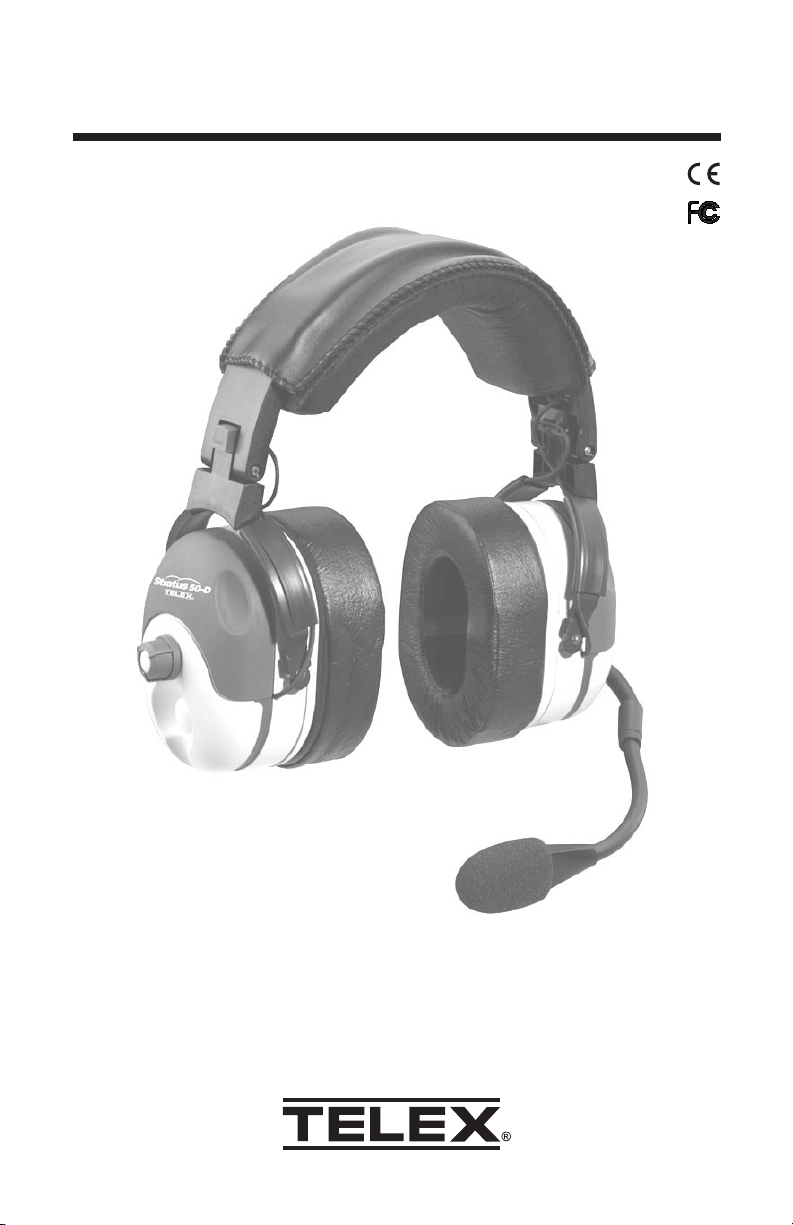
Stratus 50-D
Active Noise Reduction Headset
Page 2
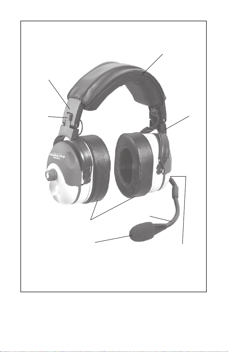
Detented Sliders
Adjust to
Any Size Head
Patented
Tension
Adjust Knob
(Comfort
Camtm)
Replaceable
Ear Cushions
Replaceable
Wide Head Pad
Earcups Pivot on
Two Planes to
Conform to
Wearer
Flexible Boom Permits
Precise Mic Placement
Noise Canceling
Electret Microphone
Stratus Reference View
Patented Ball and Socket
Jointed Boom Rotates
Overhead for Mic
Placement on Either
Side of Head
Figure 1
Page 3

General Description
The Telex Stratus 50-D is a medium-weight, active noise-reduction headset
with an amplified, noise-canceling, electret microphone. It provides up to 25+dB
digital tonal noise reduction of engine and blade noise, up to 15+dB of analog
broadband noise reduction, and 29+dB of passive noise reduction. At 90 Hz
the accumulative total is 50+dB of noise reduction.
This device complies with part 15 of the FCC
Rules, Operation is subject to the following two
conditions: (1) This device may not cause harmful interference, and (2) this device must accept
any interference received, including interference
that may cause undesired operation.
Design Features (See Figure 1)
Fit and Comfort
The Stratus 50-D incorporates unique features that allow the user to “custom
fit” the headset for comfortable operation. Among the features is a headband
design that distributes ear cushion pressure evenly over the entire ear with
no pressure points. A detented slide adjustment on the headband allows the
ear cup to be easily raised or lowered for proper fit. Contributing to the
comfort fit is a yoke design that allows the ear cup to pivot in two planes
assuring proper performance to the head.
To adjust ear cup pressure, a patented “Comfort Camtm” is rotated to one of
three tension settings. The last component in the fit and comfort is the 1”
cushion made from heat sensitive slow recovery foam which will conform to
your head to provide a perfect seal while spreading the weight over a large
area eliminating pressure points.
Boom Microphone
The Stratus 50-D utilizes an electric noise-canceling microphone to eliminate
unwanted cabin noise from entering the communication system. To assure
proper operation the mic must be positioned perpendicular to the mouth
close to the lips, slightly off center to the mouth. To facilitate pilot/co-pilot
wearing, the boom rotates up to allow the boom to be worn on the left or
right side. To minimize windscreen loss, “teeth” are designed into the mic
housing to securely hold the windscreen in place.
Cordage and Plugs
The Stratus 50-D uses shielded cables to protect against RFI (Radio
Frequency Interference) and EMF (Electro Magnetic Frequency). Strain
relief is added to the cords and plugs to provide protection from wear and
tear resulting from normal usage. Separate receiver and microphone plugs
are provided as standard. The receiver plug is set up for stereo usage but
a switch on the cordage controls stereo/mono operation.
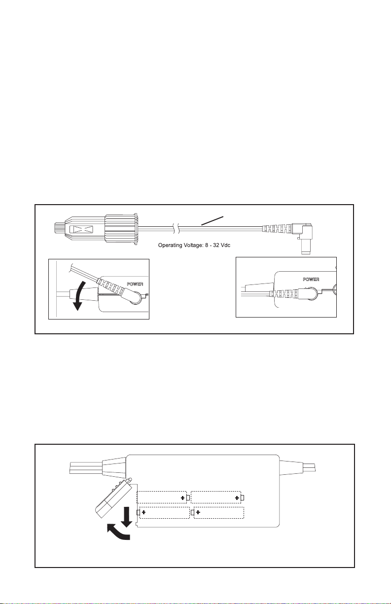
A separate power cord is provided to allow aircraft power (via cigarette
lighter adapter) to plug into the battery module on the headset cord. This
will accommodate aircraft power from 8-32 Vdc.
Page 1
Page 4
Microphone Bias Voltage Requirements
The boom microphone operates on a voltage of 8-16 VDC. Output voltage
is 50 ohms (Designed for radio input impedances from 50-600 ohms). If
you are uncertain whether your avionics equipment meets this requirement,
consult the avionics equipment manufacturer.
Headset Power
The headset will operate with either 4 AA batteries or panel power from 832 Vdc.
Panel Power Option
An optional power cord is provided for use in negative ground electrical
systems only. Do not attempt to use with positive ground electrical systems.
The power cord is designed to connect the battery module to the aircraft
power via the cigarette lighter jack.
Power Cord
450 Locking
Figure 2
Panel Power Option
Battery Power
The battery module requires 4 AA Batteries. Alkaline batteries are
recommended for best performance. Do not use nickel-cadmium
rechargeable batteries or lithium batteries.
1. Slide the battery door down in the direction of the arrow, then up to
rotate the battery door (Figure 3).
2. Place the batteries into the battery module as shown.
3. Slide the battery door back into place.
Figure 3
Battery Installation
Page 2
Page 5
Headset Operation
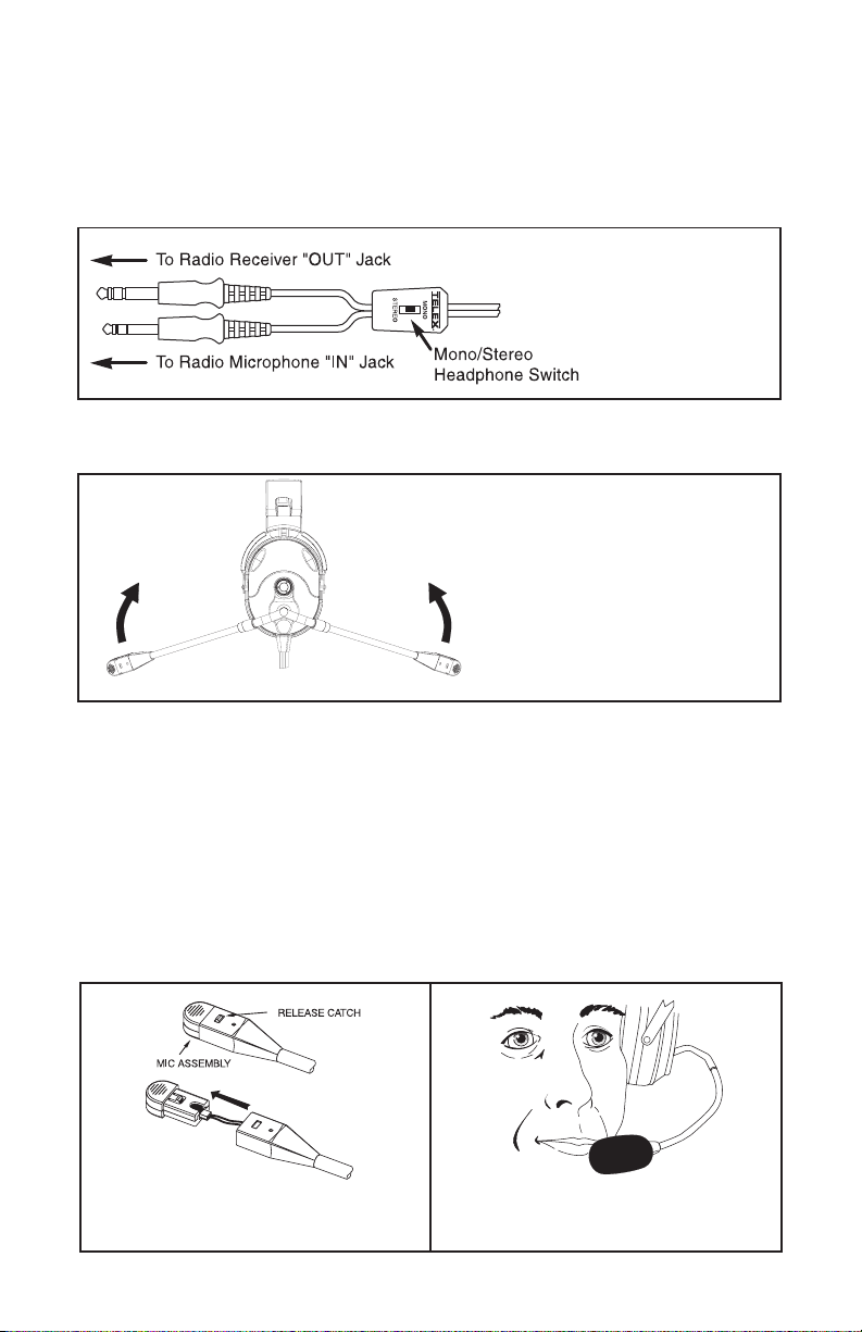
1. Connect the headset as shown in Figure 4. Set the MONO/STEREO
headphone switch to match the type of sound system in your aircraft.
If the headset is set for stereo and the intercom is set for mono, sound
will only come out of one earcup.
Figure 4
Headset Connections
2. Rotate the entire boom overhead to wear the microphone on either
the right or left side of the head (See Figure 5).
Figure 5
Microphone Placement
3. Reshape the boom so that the microphone will be in front of
the mouth.
4. For best noise cancellation, position the microphone as close to the
mouth as possible and speak in a normal voice (Figure 7).
5. For mic replacement, press the release catch and carefully pull out
the mic element. Avoid pulling the connecting wires (Figure 6).
Figure 6
Mic Element Removal
Page 3
Figure 7
Mic Placement
Page 6

Headset Operation (Cont.)
6. With the headband resting securely on the top of the head, check that
the ear cups are centered over the ears. Reposition them if necessary
by moving the headband sliders up or down (See Figure 9 on the next
page). Proper performance depends on proper fit of the headset as
described below.
7. Headband Pressure Adjustments:
There are three pressure settings. Increasing the pressure will improve
the seal between the earcup and the head for greater noise reduction.
To change the pressure setting, remove the headset and fold the
earcup inward as shown in Figure 8, then rotate the Comfort Camtm to
the desired setting. Repeat for both earcups. Both sides of the
headband should be set to the same pressure setting to keep the
headband properly centered on the head.
Side View
Headband Pressure Adjustment
Comfort Camtm Adjustment Settings
KNOB ADJUSTMENT SETTINGS
HIGH MEDIUM LOW
Top View
Figure 8
Page 4
Page 7

Headset Operation (Cont.)
8. Headband Size Adjustment
To adjust the headband size, move the earcup sliders up or down
on the headband (Figure 9). Size is properly adjusted when the
earcups are centered over the ears. It is important to adjust both
sides of the headband the same to keep the headband and pad
properly centered over the head.
Figure 9
Headband Size Adjustment
9. Volume Adjustment
When the microphone is worn
on the left side, volume is
increased by rotating the top
of the volume controls toward
the front of the head. Control
operation is reversed when
the microphone is worn on the
right side (Figure 10).
Volume
Control
Figure 10
Volume Adjustment
Page 5
Page 8

Stratus Controls
Power
Switch the ON/OFF button to turn the Stratus on or off. Green LED
indicates power on.
Low Battery
Red LED indicates 20% or less battery life remaining.
Figure 11
Stratus DSP Controller
Microphone Gain Adjustment
The microphone gain has been factory-adjusted to the nominal level required
for FAA certification, and it should normally not require readjustment. Any
changes to the mic gain should be done by a qualified avionics technician.
To access the gain trimmer, insert a small flat-blade screwdriver through the
access hole in the mic assembly. Clockwise rotation of the trimmer increases
gain.
Figure 12
Microphone Gain Adjustment
MIC GAIN
ADJUSTMENT
ACCESS
Page 6
Page 9

Ear Cushion Replacement
To remove an old ear cushion, simply grasp it and pull it off the earcup. To
install a new ear cushion, start at the top of the earcup. Place the flap on the
back of the ear cushion over the lip along the top of the earcup. Then, pull
the bottom of the ear cushion down over the lip at the bottom of the earcup.
Wiring Diagram
.206 DIA. MICROPHONE PLUG
MIC +
MIC -
.250 DIA. SPEAKER PLUG
SPKR - L
SPKR - R
Figure 13
Wiring Diagram for Fixed-Wing Version
RED
BLK
SHLD
RED
BLUE
BLK
WHITE
SHLD
SPKR - GND
Page 7
Page 10

Specifications
Receivers:
Type: Dynamic
Frequency Response: 50 Hz - 10 kHz
Sensitivity: 95 ± 5 dB SPL (1 kHz, 1 mW input)
Impedance (Max. Volume):
Stereo.........................................300 ohms per side
Monaural...................................................150 ohms
Headset Power: 4AA Batteries or Panel Power from 8-32 Vdc
Microphone and Amplifier:
Element Type: Noise-canceling electret
Frequency Response: 100 Hz - 3.5 kHz
Sensitivity: -53 +2/-1 dB (ref:1 V/ µbar at 1 kHz with 12 Vdc supply
voltage and 470 ohm DC, 150 ohm AC load)
Matching Impedance: 50-600 ohms
Gain Adjustment Range: ± 5 dB (clockwise rotation increases gain)
Operating Voltage: (supplied by aircraft radio) 8-16 Vdc
Cordage:
Straight Y-cord, 9 ft (2.74 m)
Connectors:
Microphone Plug: PJ-068 or equivalent
Reciever Plug: PJ-055 or equivalent
DC Jack: 2.5mm Dia. Pin
Weight:
Effective Head Weight: Approximately 18.5 oz. (524 g)
Color: Lt. Grey/Purple
Page 8
Page 11

ORDERING INFORMATION
Stratus Headset, with electret mic, battery module,
and carrying case . ............................................. Catalog no. 301125-000
Aircraft Power Cord ............................................ Catalog no. 550216-001
1” Foam-filled ear cushions (package of 2) ......... Catalog no. 800456-015
Headband Pad.................................................... Catalog no. 800456-017
Replacement electret microphone ...................... Catalog no. 800136-000
Microphone windscreen (electret) ....................... Catalog no. 800456-000
Clothing Clip ....................................................... Catalog no. 590637-000
Zippered Pouch .................................................. Catalog no. 500266-000
Page 9
Page 12

LIMITED WARRANTY — VALID ONLY IN UNITED STATES AND CANADA
TELEX Communications, Inc. (“Telex”) warrants to the user, who originally purchased the
product delivered with this card, that the product will be free from defects in material and
workmanship for the following periods after such date of purchase: Material 36 months,
workmanship 36 months. Telex will, at its option, repair or replace, free of charge, such defective
products subject to the following conditions:
1. Delivery of the product or parts postage prepaid to the Telex dealer, authorized service
facility or factory.
2. Determination by Telex that a defect exists and is covered by the limited warranty. Defects
due to alteration, repair by an unauthorized person, insertion of non-Telex parts, misuse,
accidental damage, use of the equipment for purposes other than those for which it was
designed, and the like, are not covered by this limited warranty and repairs thereof will
be subject to normal service charges.
3. Repairs and replacement parts are covered under this limited warranty only for the
unexpired term of the original limited warranty.
4. Products purchased from unauthorized dealers are not warranted.
5. You must fill out and return the attached registration card within 10 days after such
purchase or this limited warranty is void.
THIS LIMITED WARRANTY IS EXPRESSLY IN LIEU OF ANY EXPRESS OR IMPLIED
WARRANTY, INCLUDING ANY IMPLIED WARRANTY OF MERCHANTABILITY OR FITNESS
FOR A PARTICULAR PURPOSE WHICH EXTENDS BEYOND THE TERM HEREOF. THE
REMEDIES PROVIDED BY THIS LIMITED WARRANTY ARE THE ONLY REMEDIES
AVAILABLE TO ANY PERSON. NO PERSON HAS ANY AUTHORITY TO BIND TELEX TO
ANY REPRESENTATION OR WARRANTY OTHER THAN THOSE PROVIDED BY THIS
LIMITED WARRANTY. TELEX SHALL NOT BE LIABLE FOR ANY INCIDENTAL OR
CONSEQUENTIAL DAMAGES CAUSED BY FAILURE OR OTHERWISE OF THE PRODUCT.
Some states do not allow exclusions or limitations of incidental or consequential damages or
limitations on how long an implied warranty lasts, so the limitations or exclusions herein may
not apply to you. This warranty gives you specific legal rights, and you may also have other
rights which vary from state to state.
Page 10
Page 13

CUSTOMER SERVICE
For information or technical assistance, call or write to Telex at:
Customer Service Department
Telex Communications, Inc.
12000 Portland Ave. So.
Burnsville, MN 55337 U.S.A.
(952) 884-4051
When returning equipment for repair, please enclose an explanation of
the problem. And, if the equipment is covered under warranty, please
enclose a copy of your proof of purchase. The equipment must be
accompanied by documentation stating your name, return address, and
telephone number.
Return equipment for factory repair to:
Customer Service Department
Telex Communications, Inc.
1720 East 14th St.
Glencoe, MN 55336 U.S.A.
(320) 864-3177
Warranty Repairs - If in warranty, no charge will be made for the repairs.
Equipment being returned for warranty repair must be sent prepaid and
will be returned prepaid.
Non-Warranty Repairs - Equipment that is not under warranty must be
sent prepaid to Telex. If requested, an estimate of repair costs will be
issued prior to service. Once your approval for repair, and repair of
equipment is completed, the equipment will be returned on a collect
basis. Collect charges may be avoided by sending a signed check for
payment in full along with your signed estimate approval form (the
estimate includes the shipping charge).
Page 11
Page 14

Notes
Page 15

Notes
Page 16

38110-073 Rev D 7/02
 Loading...