


Telex
Operating Instructions
ST300
Transmitter
SR-400
17 Channel Receiver
SR-50
Single Channel Receiver
INTRODUCTION
WHAT IS THE TELEX SOUND
ENHANCEMENT SYSTEM?
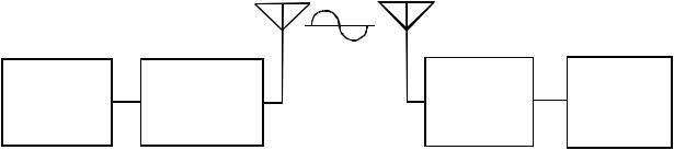
Transmitter: The transmitter generates and amplifies a RF (Radio Frequency) carrier signal, modulates this carrier with the microphone signal, and radiates the modulated RF carrier.
Receiver: The FM VHF receiver is tuned to the frequency of the transmitter. The receiver picks up the radiated RF signal from the transmitter through the antenna and converts the RF signal into audio voltages for use with an earphone, headphone, button receiver, neckloop, etc. The receiver frequency must be matched to the transmitter frequency.
WHAT FREQUENCY BAND DOES THE TELEX SYSTEM OPERATE IN?
The Telex Systems feature a synthesized transmitter and single channel or synthesized receivers operating in the VHF Band between 72-76 MHz. See Table 1 for standard frequencies available.
Each transmitter channel can be utilized by any number of receivers in any given area. Up to eight simultaneous systems can be used, and with proper placement of adjacent channels, up to ten systems can be used.
ANT. ANT.
|
|
RF CARRIER |
|
|
|
|
SIGNAL |
|
|
SOUND |
TRANSMITTER |
FM |
EARPHONE |
|
SOURCE |
RECEIVER |
|||
|
|
Figure 1
Block Diagram of Typical Sound Enhancement System
-1-

OFTEN ASKED QUESTIONS
Question: Can more than one system be used simultaneously?
Answer: Yes but never on the same frequency. You will need to have different frequencies for every receiver/transmitter combination. All transmitters are factory set for specific frequencies.
Question: Is the system more sensitive in any one particular direction?
Answer: No, the transmitter’s antenna radiates equally in all directions, but the signal is attenuated by your body, walls or other surrounding objects. The receiving antenna is essentially sensitive in all directions as well.
Question: Can the receiver receive other transmissions when the transmitter is turned off?
Answer: Yes it can. Telex systems operate in the VHF Band between 72-76 MHz. However, it is not susceptible to radio wave skip, CB’ers or standard FM radio transmissions.
The frequency your system operates on is computer selected for least interference, but there is no such thing as a 100% clear channel all the time, anywhere in the U.S.A., forever!
If the system is going to be used in a permanent fixed location, it should operate interference free until such a time or date when someone else begins using the same frequency.
If the system is going to be moving among various locations, you may run into occasional frequency conflicts.
Whenever the system is in use, the transmitter should be left on to prevent the receiver from picking up outside interference.
AVAILABLE FREQUENCIES
|
CHANNEL |
FREQ. in MHz |
|
|
|
|
|
|
A |
72.100 |
|
|
|
|
|
|
B |
72.200 |
|
|
|
|
|
|
C |
72.300 |
|
|
|
|
|
|
D |
72.400 |
|
|
E |
72.500 |
|
|
|
|
|
|
F |
72.600 |
|
|
G |
72.700 |
|
|
|
|
|
|
H |
72.800 |
|
|
I |
72.900 |
|
|
|
|
|
|
J |
75.500 |
|
|
|
|
|
|
K |
75.600 |
|
|
|
|
|
|
L |
75.700 |
|
|
|
|
|
|
M |
75.800 |
|
|
|
|
|
|
N |
75.900 |
|
|
|
|
|
|
O |
74.700 |
|
|
|
|
|
|
P |
75.300 |
|
|
Q |
75.400 |
|
|
|
|
|
Table 1
Frequencies Available
-2-
TECHNICAL INFORMATION
SR-50 RECEIVER
GENERAL DESCRIPTION SR-50
The Telex SR-50 Receiver is a component of a system which operates on 17 factory preset channels in the 72 to 76 MHz frequency band. The receivers are designed to be used with Telex ST-300 and PST-170 transmitters, but they can be used with other brands of transmitters in the 72 to 76 MHz band provided the frequencies match.
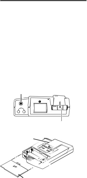
OPERATING FEATURES
Volume OFF/ON Control: The thumbwheel control serves as both an off/on switch and as a volume control.
HEADPHONE JACK
TelexR
A
CHANNEL
VOLUME OFF/ON CONTROL
BELT CLIP
The receiver is turned off when the control is in the extreme counterclockwise position, when viewed from the rear and the volume is loudest when the control is in the extreme clockwise position.
Headphone Jack: The receiver jack accepts a 0.140-inch (3.5 mm) diameter miniature phone plug. A variety of accessory units can be plugged into the jack for reception of the desired channels being transmitted.
Belt Clip: The belt clip supplied is detachable by spreading the wire apart at the tops and removing one side of the clip form the case and then the other.

 BATTERY
ORIENTATION
BATTERY COMPARTMENT COVER
Figure 2
Operating Features SR-50
-3-
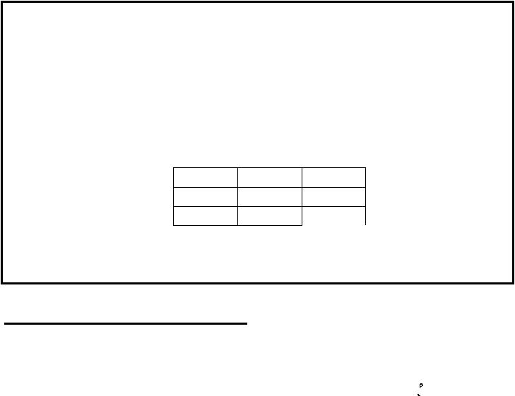
SPECIFICATIONS |
|
|
SR-50 Single Channel Receiver |
|
|
Temperature Range ..................................................................................................... |
|
0 to +50 degrees C |
Supply Voltage ............................................................................................... |
|
2-3 Volts, (2) AA Batteries |
Battery Life .............................................................................................................. |
|
20-30 Hrs - Alkaline |
|
|
8-10 Hrs - Nicad |
Sensitivity (12 dB SINAD @ 25 kHz deviation) ................................... |
|
0.5µ V typical/1µ V maximum |
Distortion ............................................................................................................................... |
|
less than 2% |
Frequency Response - 100 Hz-10 kHz ............................................................. |
|
Less than 3 dB Variation |
Audio Output @ 10% Distortion |
|
|
Battery Input |
2.0V |
3.0V |
Voltage |
|
|
8 ohm |
15 mW |
80 mW |
32 ohm |
10 mW |
50 mW |
Controls and Connections ................................................................................ |
|
Volume OFF/ON Switch, |
|
|
Audio Output Jack |
SR-400 SYNTHESIZED
RECEIVER
General Description SR-400
The Telex SR-400 Receiver is a component of a system which operates on seventeen user selectable channels in the 72 to 76 MHz frequency band. The receivers are designed to be used with the Telex ST-300 and PST-170 Transmitters.
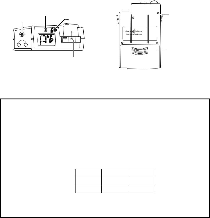
Operating Features
Volume OFF/ON Control: This thumbwheel control serves as both an off/on switch and as a volume control. The receiver is turned off when the control is in the extreme counter-clockwise position, when viewed from the rear, and the volume is loudest when the control is in the extreme clockwise position.
NOTE: A headphone or other device must be plugged in the headphone jack in order to turn on the SR-400. This is to prevent draining the batteries if the switch is accidently left on.
Treble Control: A push button treble control is provided to enhance higher frequency audio when the button is engaged, indicated by  .
.
Headphone Jack: The receiver jack accepts a 0.140-inch (3.5 mm) diameter miniature plug. A variety of accessory units can be plugged into this jack for listening.
Belt Clip: The belt clip supplied is detachable by spreading the wire apart at the tops and removing one side of the clip form the case and then the other.
-4-
SET |
|
|
SWITCH |
|
|
BUTTON |
|
BELT CLIP |
|
|
|
HEADPHONE JACK |
TREBLE CONTROL |
|
SET |
|
Telex |
|
SR-400 |
|
|
|
|
|
P/N:71166000 |
S/N:00001 |
|
FCC ID: B5DE405 |
|
 E.D.R.
BATTERY COMPARTMENT
VOLUME OFF/ON CONTROL
Figure 3 |
|
|
Operating Features SR-400 |
|
|
SPECIFICATIONS |
|
|
SR-400 17 Channel Synthesized Receiver |
|
|
Temperature Range ..................................................................................................... |
|
0 to +50 degrees C |
Supply Voltage ............................................................................................... |
|
2-3 Volts, (2) AA Batteries |
Battery Life .............................................................................................................. |
|
16-20 Hrs - Alkaline |
|
|
12-16 Hrs - Nickel Metal Hydride |
|
|
8-10 Hrs - Nickel-cadmium |
Frequency Response .................................................................................................... |
|
100-10 kHz ±3 dB |
Sensitivity (12 dB SINAD @ 74 MHz)................................................................................... |
|
1µ V max. |
Distortion ............................................................................................................................... |
|
less than 2% |
Audio Output @ 10% Distortion |
8 ohm |
32 ohm |
Battery Input |
||
Voltage |
|
|
2.0 V |
15 mW |
10 mW |
3.0 V |
80 mW |
50 mW |
Controls and Connections................................................................................. |
|
Volume OFF/ON Switch; |
|
Treble Control Switch; Channel Selection Switch |
|
|
|
Audio Output Jack |
-5-
 Loading...