


Telex
Operating Instructions
RadioCom™
BTR-1, TR-1
Professional
Wireless
Intercom System
Table of Contents
Section 1 Introduction . . . . . . . . . . . . . . . . . . . . . . . . . . . . . . . . . . . . . . . . . . . . . . 1-1
General Description . . . . . . . . . . . . . . . . . . . . . . . . . . . . . . . . . . . . . . . . . . . . . . . . . . . . . . . . . . . . . . . . . . . . . . . . . . 1-1
System Features . . . . . . . . . . . . . . . . . . . . . . . . . . . . . . . . . . . . . . . . . . . . . . . . . . . . . . . . . . . . . . . . . . . . . . . . . . . . . 1-1
BTR-1 Block Diagram. . . . . . . . . . . . . . . . . . . . . . . . . . . . . . . . . . . . . . . . . . . . . . . . . . . . . . . . . . . . . . . . . . . . . . . . 1-3
TR-1 Block Diagram . . . . . . . . . . . . . . . . . . . . . . . . . . . . . . . . . . . . . . . . . . . . . . . . . . . . . . . . . . . . . . . . . . . . . . . . . 1-4
Section 2 BTR-1 Base Station . . . . . . . . . . . . . . . . . . . . . . . . . . . . . . . . . . . . . . . . 2-1
Controls and Connections - Front Panel . . . . . . . . . . . . . . . . . . . . . . . . . . . . . . . . . . . . . . . . . . . . . . . . . . . . . . . . . . 2-1
Controls and Connections - Rear Panel . . . . . . . . . . . . . . . . . . . . . . . . . . . . . . . . . . . . . . . . . . . . . . . . . . . . . . . . . . . 2-2
Section 3 TR-1 Beltpack . . . . . . . . . . . . . . . . . . . . . . . . . . . . . . . . . . . . . . . . . . . . 3-1
Controls and Connections - Top Panel. . . . . . . . . . . . . . . . . . . . . . . . . . . . . . . . . . . . . . . . . . . . . . . . . . . . . . . . . . . . 3-1
Controls and Connections - Rear Panel . . . . . . . . . . . . . . . . . . . . . . . . . . . . . . . . . . . . . . . . . . . . . . . . . . . . . . . . . . . 3-2
Section 4 Specifications . . . . . . . . . . . . . . . . . . . . . . . . . . . . . . . . . . . . . . . . . . . . . 4-1
BTR-1 Specifications. . . . . . . . . . . . . . . . . . . . . . . . . . . . . . . . . . . . . . . . . . . . . . . . . . . . . . . . . . . . . . . . . . . . . . . . . 4-1
TR-1 Specifications . . . . . . . . . . . . . . . . . . . . . . . . . . . . . . . . . . . . . . . . . . . . . . . . . . . . . . . . . . . . . . . . . . . . . . . . . . 4-2
Section 5 Initial Equipment Set-Up . . . . . . . . . . . . . . . . . . . . . . . . . . . . . . . . . . . 5-1
Unpacking . . . . . . . . . . . . . . . . . . . . . . . . . . . . . . . . . . . . . . . . . . . . . . . . . . . . . . . . . . . . . . . . . . . . . . . . . . . . . . . . . 5-1
Rack Mounting . . . . . . . . . . . . . . . . . . . . . . . . . . . . . . . . . . . . . . . . . . . . . . . . . . . . . . . . . . . . . . . . . . . . . . . . . . . . . 5-2
Rack Mounting a Single Base Station . . . . . . . . . . . . . . . . . . . . . . . . . . . . . . . . . . . . . . . . . . . . . . . . . . . . . . . . . . . . 5-2
Rack Mounting Two Base Stations Side-by-Side . . . . . . . . . . . . . . . . . . . . . . . . . . . . . . . . . . . . . . . . . . . . . . . . . . . 5-2
Antenna Connection . . . . . . . . . . . . . . . . . . . . . . . . . . . . . . . . . . . . . . . . . . . . . . . . . . . . . . . . . . . . . . . . . . . . . . . . . 5-3
Antenna Polarization . . . . . . . . . . . . . . . . . . . . . . . . . . . . . . . . . . . . . . . . . . . . . . . . . . . . . . . . . . . . . . . . . . . . . . . . . 5-3
Distance Between Antennas . . . . . . . . . . . . . . . . . . . . . . . . . . . . . . . . . . . . . . . . . . . . . . . . . . . . . . . . . . . . . . . . . . . 5-3
Antenna Placement . . . . . . . . . . . . . . . . . . . . . . . . . . . . . . . . . . . . . . . . . . . . . . . . . . . . . . . . . . . . . . . . . . . . . . . . . . 5-3
Section 6 BTR-1 Operation. . . . . . . . . . . . . . . . . . . . . . . . . . . . . . . . . . . . . . . . . . 6-1
Basic Operational Description . . . . . . . . . . . . . . . . . . . . . . . . . . . . . . . . . . . . . . . . . . . . . . . . . . . . . . . . . . . . . . . . . . 6-1 System Quick Start . . . . . . . . . . . . . . . . . . . . . . . . . . . . . . . . . . . . . . . . . . . . . . . . . . . . . . . . . . . . . . . . . . . . . . . 6-1 Interfacing to the BTR-1 . . . . . . . . . . . . . . . . . . . . . . . . . . . . . . . . . . . . . . . . . . . . . . . . . . . . . . . . . . . . . . . . . . . . . . 6-3 TX/RX Antennas . . . . . . . . . . . . . . . . . . . . . . . . . . . . . . . . . . . . . . . . . . . . . . . . . . . . . . . . . . . . . . . . . . . . . . . . 6-3 2W Intercom Ports . . . . . . . . . . . . . . . . . . . . . . . . . . . . . . . . . . . . . . . . . . . . . . . . . . . . . . . . . . . . . . . . . . . . . . . 6-3 4W Intercom Ports . . . . . . . . . . . . . . . . . . . . . . . . . . . . . . . . . . . . . . . . . . . . . . . . . . . . . . . . . . . . . . . . . . . . . . . 6-4 Auxiliary Port . . . . . . . . . . . . . . . . . . . . . . . . . . . . . . . . . . . . . . . . . . . . . . . . . . . . . . . . . . . . . . . . . . . . . . . . . . . 6-4 CAN Bus. . . . . . . . . . . . . . . . . . . . . . . . . . . . . . . . . . . . . . . . . . . . . . . . . . . . . . . . . . . . . . . . . . . . . . . . . . . . . . . 6-4 Relay . . . . . . . . . . . . . . . . . . . . . . . . . . . . . . . . . . . . . . . . . . . . . . . . . . . . . . . . . . . . . . . . . . . . . . . . . . . . . . . . . . 6-4 Local Headset . . . . . . . . . . . . . . . . . . . . . . . . . . . . . . . . . . . . . . . . . . . . . . . . . . . . . . . . . . . . . . . . . . . . . . . . . . . 6-5 Powering the Base Station . . . . . . . . . . . . . . . . . . . . . . . . . . . . . . . . . . . . . . . . . . . . . . . . . . . . . . . . . . . . . . . . . . . . . 6-5 Start-up . . . . . . . . . . . . . . . . . . . . . . . . . . . . . . . . . . . . . . . . . . . . . . . . . . . . . . . . . . . . . . . . . . . . . . . . . . . . . . . . . . . 6-5 Status Screen . . . . . . . . . . . . . . . . . . . . . . . . . . . . . . . . . . . . . . . . . . . . . . . . . . . . . . . . . . . . . . . . . . . . . . . . . . . . . . . 6-5 Encryption Code . . . . . . . . . . . . . . . . . . . . . . . . . . . . . . . . . . . . . . . . . . . . . . . . . . . . . . . . . . . . . . . . . . . . . . . . . . . . 6-6 System Settings . . . . . . . . . . . . . . . . . . . . . . . . . . . . . . . . . . . . . . . . . . . . . . . . . . . . . . . . . . . . . . . . . . . . . . . . . . . . . 6-6 Name and Number . . . . . . . . . . . . . . . . . . . . . . . . . . . . . . . . . . . . . . . . . . . . . . . . . . . . . . . . . . . . . . . . . . . . . . . 6-6 Base Main Settings . . . . . . . . . . . . . . . . . . . . . . . . . . . . . . . . . . . . . . . . . . . . . . . . . . . . . . . . . . . . . . . . . . . . . . . 6-6 Intercom Type . . . . . . . . . . . . . . . . . . . . . . . . . . . . . . . . . . . . . . . . . . . . . . . . . . . . . . . . . . . . . . . . . . . . . . . . 6-7 Auxiliary Line . . . . . . . . . . . . . . . . . . . . . . . . . . . . . . . . . . . . . . . . . . . . . . . . . . . . . . . . . . . . . . . . . . . . . . . . 6-7 Base TX Power . . . . . . . . . . . . . . . . . . . . . . . . . . . . . . . . . . . . . . . . . . . . . . . . . . . . . . . . . . . . . . . . . . . . . . . 6-7 Sidetone Levels . . . . . . . . . . . . . . . . . . . . . . . . . . . . . . . . . . . . . . . . . . . . . . . . . . . . . . . . . . . . . . . . . . . . . . . 6-7 Frequency Settings . . . . . . . . . . . . . . . . . . . . . . . . . . . . . . . . . . . . . . . . . . . . . . . . . . . . . . . . . . . . . . . . . . . . . . . 6-7
Intercom Settings . . . . . . . . . . . . . . . . . . . . . . . . . . . . . . . . . . . . . . . . . . . . . . . . . . . . . . . . . . . . . . . . . . . . . . . . . . . . 6-8
RF Meter . . . . . . . . . . . . . . . . . . . . . . . . . . . . . . . . . . . . . . . . . . . . . . . . . . . . . . . . . . . . . . . . . . . . . . . . . . . . . . . . . . 6-9
ClearScanä . . . . . . . . . . . . . . . . . . . . . . . . . . . . . . . . . . . . . . . . . . . . . . . . . . . . . . . . . . . . . . . . . . . . . . . . . . . . . . . . 6-9
Special Button Functions . . . . . . . . . . . . . . . . . . . . . . . . . . . . . . . . . . . . . . . . . . . . . . . . . . . . . . . . . . . . . . . . . . . . . 6-10
-i-
Table of Contents (continued)
Section 7 TR-1 Operation . . . . . . . . . . . . . . . . . . . . . . . . . . . . . . . . . . . . . . . . . . . . |
7-1 |
Basic Operational Description . . . . . . . . . . . . . . . . . . . . . . . . . . . . . . . . . . . . . . . . . . . . . . . . . . . . . . . . . . . . . . . . . . 7-1 System Quick Start . . . . . . . . . . . . . . . . . . . . . . . . . . . . . . . . . . . . . . . . . . . . . . . . . . . . . . . . . . . . . . . . . . . . . . . 7-1 Battery Installation. . . . . . . . . . . . . . . . . . . . . . . . . . . . . . . . . . . . . . . . . . . . . . . . . . . . . . . . . . . . . . . . . . . . . . . . . . . 7-2 Transmit Modes (PT TALK, PT TX). . . . . . . . . . . . . . . . . . . . . . . . . . . . . . . . . . . . . . . . . . . . . . . . . . . . . . . . . . . . . 7-3 Headset Connection . . . . . . . . . . . . . . . . . . . . . . . . . . . . . . . . . . . . . . . . . . . . . . . . . . . . . . . . . . . . . . . . . . . . . . . . . . 7-3 Sidetone . . . . . . . . . . . . . . . . . . . . . . . . . . . . . . . . . . . . . . . . . . . . . . . . . . . . . . . . . . . . . . . . . . . . . . . . . . . . . . . . . . . 7-3 Antenna Connections. . . . . . . . . . . . . . . . . . . . . . . . . . . . . . . . . . . . . . . . . . . . . . . . . . . . . . . . . . . . . . . . . . . . . . . . . 7-3 TR-1 Top Panel . . . . . . . . . . . . . . . . . . . . . . . . . . . . . . . . . . . . . . . . . . . . . . . . . . . . . . . . . . . . . . . . . . . . . . . . . . . . . 7-4 On/Off Volume Control . . . . . . . . . . . . . . . . . . . . . . . . . . . . . . . . . . . . . . . . . . . . . . . . . . . . . . . . . . . . . . . . . . . 7-4 BAT/O.M. Light . . . . . . . . . . . . . . . . . . . . . . . . . . . . . . . . . . . . . . . . . . . . . . . . . . . . . . . . . . . . . . . . . . . . . . . . . 7-4 Talk button . . . . . . . . . . . . . . . . . . . . . . . . . . . . . . . . . . . . . . . . . . . . . . . . . . . . . . . . . . . . . . . . . . . . . . . . . . . . . 7-4 A/B Selection Switch . . . . . . . . . . . . . . . . . . . . . . . . . . . . . . . . . . . . . . . . . . . . . . . . . . . . . . . . . . . . . . . . . . . . . 7-4 C Pushbutton. . . . . . . . . . . . . . . . . . . . . . . . . . . . . . . . . . . . . . . . . . . . . . . . . . . . . . . . . . . . . . . . . . . . . . . . . . . . 7-4
Group and Channels . . . . . . . . . . . . . . . . . . . . . . . . . . . . . . . . . . . . . . . . . . . . . . . . . . . . . . . . . . . . . . . . . . . . . . . . . 7-5 Transmit Frequency . . . . . . . . . . . . . . . . . . . . . . . . . . . . . . . . . . . . . . . . . . . . . . . . . . . . . . . . . . . . . . . . . . . . . . . . . . 7-5 Receiver Frequency . . . . . . . . . . . . . . . . . . . . . . . . . . . . . . . . . . . . . . . . . . . . . . . . . . . . . . . . . . . . . . . . . . . . . . . . . . 7-6 Battery Display . . . . . . . . . . . . . . . . . . . . . . . . . . . . . . . . . . . . . . . . . . . . . . . . . . . . . . . . . . . . . . . . . . . . . . . . . . . . . 7-6 Microphone Gain . . . . . . . . . . . . . . . . . . . . . . . . . . . . . . . . . . . . . . . . . . . . . . . . . . . . . . . . . . . . . . . . . . . . . . . . . . . . 7-7 Transmit Power . . . . . . . . . . . . . . . . . . . . . . . . . . . . . . . . . . . . . . . . . . . . . . . . . . . . . . . . . . . . . . . . . . . . . . . . . . . . . 7-7 Encryption Code . . . . . . . . . . . . . . . . . . . . . . . . . . . . . . . . . . . . . . . . . . . . . . . . . . . . . . . . . . . . . . . . . . . . . . . . . . . . 7-7 Serial Number Code. . . . . . . . . . . . . . . . . . . . . . . . . . . . . . . . . . . . . . . . . . . . . . . . . . . . . . . . . . . . . . . . . . . . . . . . . . 7-8 Auto Programing . . . . . . . . . . . . . . . . . . . . . . . . . . . . . . . . . . . . . . . . . . . . . . . . . . . . . . . . . . . . . . . . . . . . . . . . . . . . 7-8 Software/Channel Map Version . . . . . . . . . . . . . . . . . . . . . . . . . . . . . . . . . . . . . . . . . . . . . . . . . . . . . . . . . . . . . . . . . 7-8 ClearScan . . . . . . . . . . . . . . . . . . . . . . . . . . . . . . . . . . . . . . . . . . . . . . . . . . . . . . . . . . . . . . . . . . . . . . . . . . . . . . . . . . 7-8 Lock Out . . . . . . . . . . . . . . . . . . . . . . . . . . . . . . . . . . . . . . . . . . . . . . . . . . . . . . . . . . . . . . . . . . . . . . . . . . . . . . . . . . 7-9 1st Use . . . . . . . . . . . . . . . . . . . . . . . . . . . . . . . . . . . . . . . . . . . . . . . . . . . . . . . . . . . . . . . . . . . . . . . . . . . . . . . . . . . . 7-9 Factory Reset . . . . . . . . . . . . . . . . . . . . . . . . . . . . . . . . . . . . . . . . . . . . . . . . . . . . . . . . . . . . . . . . . . . . . . . . . . . . . . . 7-9
Section 8 TR-1 Menu Structure . . . . . . . . . . . . . . . . . . . . . . . . . . . . . . . . . . . . . . 8-1
Section 9 BTR-1 Menu Structure . . . . . . . . . . . . . . . . . . . . . . . . . . . . . . . . . . . . . 9-1
Section 10 Frequency Bands . . . . . . . . . . . . . . . . . . . . . . . . . . . . . . . . . . . . . . . . 10-1
Section 11 Trouble Shooting. . . . . . . . . . . . . . . . . . . . . . . . . . . . . . . . . . . . . . . . . 11-1
Section 12 Battery Information . . . . . . . . . . . . . . . . . . . . . . . . . . . . . . . . . . . . . . 12-1
Section 13 2-Wire Intercom Specifications. . . . . . . . . . . . . . . . . . . . . . . . . . . . . 13-1
Section 14 FCC Information . . . . . . . . . . . . . . . . . . . . . . . . . . . . . . . . . . . . . . . . 14-1
Section 15 Software License. . . . . . . . . . . . . . . . . . . . . . . . . . . . . . . . . . . . . . . . . 15-1
Section 16 Accessories and Replacement Parts . . . . . . . . . . . . . . . . . . . . . . . . . 16-1
-ii-

Section
1
Introduction
General Description
The Telex RadioCom™ BTR-1 UHF wireless intercom systems is the ultimate in reliable, high performance, encrypted full duplex communications.
The BTR-1 system includes the BTR-1 frequency agile base station and a TR-1 frequency agile beltpack. The BTR-1 system provides full duplex, encrypted digital communication.
The base station provides the beltpack with access to a six intercom port matrix of 2-wire systems or communication to a 4-wire intercom system. The system can interface with Audiocom® (Telex), RTS® TW, Clear-Com® 2-wire intercom systems as well as 4 wire communication systems.
In addition to the 2 and 4-wire intercom systems the base station provides connections for auxiliary balanced audio input and output, as well as relay closure and the ability for using one of the six intercom lines as a wireless only communication intercom. The system is also perfectly suited for stand-alone operation.
System Features
•Frequency agile base station and beltpacks.
•No external computer/device required to select frequencies.
•Telex Communications proprietary digitally encrypted wireless communication between the base station and
beltpack.
•AC or DC operation in the 12 to15 Volt range.
•Backlit base station LCD allows the user to easily monitor the beltpack’s status.
•The frequencies of a beltpack may be changed at the beltpack or from the base station.
•Beltpack units contained in a weather and shock resistant die cast magnesium case.
The BTR-1 has been designed for reliable, efficient operation. Operating in the 482 to 746 MHz range. The unit has expansion ability to add dozens of base stations to create a system. The high-efficiency beltpack provides up to 9 hours of uninterrupted operation using standard alkaline batteries.
•Six channels of 2-Wire intercom.
•Compatible with Audiocom® (Telex), RTS TW, Clear-Com®, RTS Matrix and other wired intercom types.
•Relay contact closure on the base station that can be activated from the beltpack.
•ClearScanä function to automatically find the best channels on which to operate.
•Base stations are table or rack mountable.
RTS® and Audiocom® are registered trademarks of Telex Communications, Inc. Clear-Com® is a registered trademark of Clear-Com Intercom Systems, Inc.
1-1
1-2 Blank

|
|
|
|
|
|
|
|
|
|
|
|
|
TRANSMITTER |
|
LOW PASS |
|
|
|
A/D |
|
PRE |
|
COMPRESSOR |
|
|
FILTER |
|
|
|
|
|
EMPHASIS |
|
|
|
|
|
|
|
|
DSP |
|
|
|
|
||
|
|
|
|
|
|
|
|
|
|
|
|
|
RECEIVER |
|
SQUARING |
|
|
|
D/A |
|
DE |
|
EXPANDER |
|
|
|
AMP |
|
|
|
|
|
EMPHASIS |
|
|
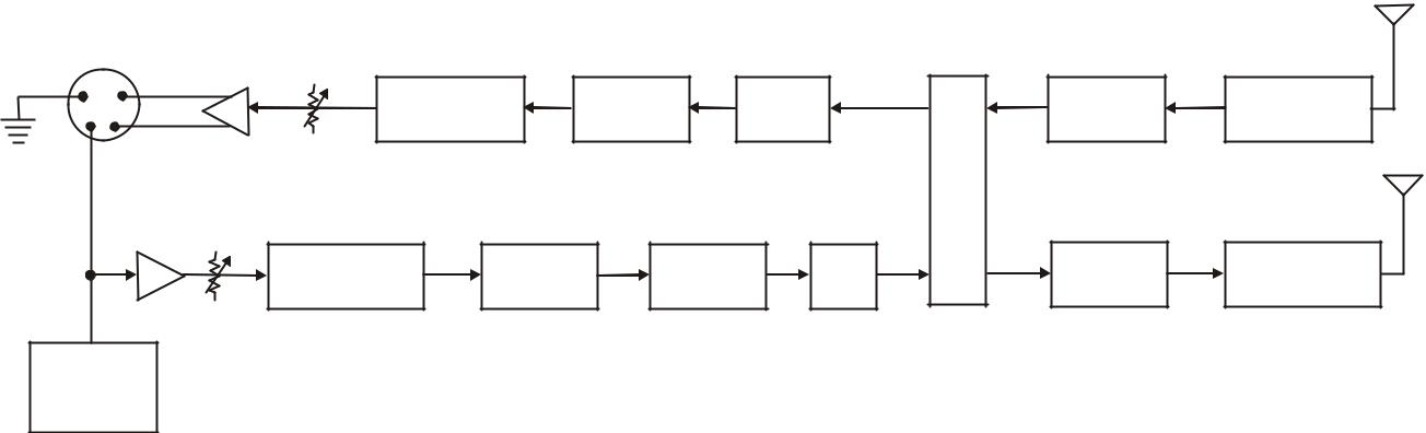
BTR-1 BLOCK DIAGRAM
HEADSET
AUX
AUX |
HS |
MIC |
OUT |
LEVEL |
GAIN |
AUX
IN
AUX IN
GLOBAL/LOCAL
2W |
4W |
4W |
2W |
|
4W |
4W |
|
|
IN |
OUT |
|
4 WIRE
LISTEN 1A
INPUT 1 OUTPUT 1 LISTEN 1B LISTEN 2A |
INPUT 2 |
OUTPUT 2 LISTEN 2B LISTEN 3A |
INPUT 3 OUTPUT 3 LISTEN 3B LISTEN 4A |
INPUT 4 OUTPUT 4 LISTEN 4B LISTEN 5A |
INPUT 5 OUTPUT 5 LISTEN 5B LISTEN 6A |
INPUT 6 OUTPUT 6 LISTEN 6B |
INTERCOM |
INTERCOM |
INTERCOM |
INTERCOM |
INTERCOM |
INTERCOM |
PORT 1 |
PORT 2 |
PORT 3 |
PORT 4 |
PORT 5 |
PORT 6 |
Figure 1-1
BTR-1 Block Diagram
1-3
|
|
|
|
|
|
RX |
|
1 |
4 |
VOLUME |
|
|
|
|
|
|
DE |
D/A |
SQUARING |
RECEIVER |
|||
2 |
3 |
EXPANDER |
|||||
EMPHASIS |
AMP |
||||||
|
|
|
|
|
|||
|
|
MIC |
|
DSP |
|
TX |
|
|
|
|
|
|
|
||
|
|
GAIN |
|
|
|
|
|
|
|
AUDIO |
PRE |
A/D |
LOW PASS |
TRANSMITTER |
|
|
|
COMPRESSOR |
EMPHASIS |
FILTER |
|||
|
|
GATE |
|
|
ELECTRET/
DYNAMIC
DETECT
Figure 1-2
TR-1 Block Diagram
1-4
Section
2
BTR-1 Base Station
Controls and Connections - Front Panel
1 |
2 |
3 |
4 |
6 |
7 |
9 |
11 |
2 |
4 |
5 |
8 |
10 |
CONTRAST ADJUST
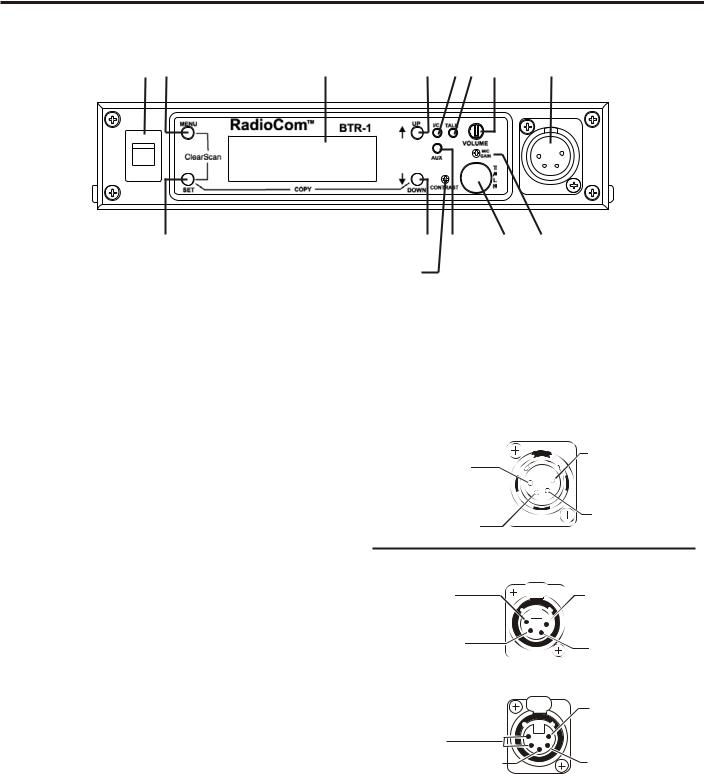
Figure 2-1
BTR-1 - Front Panel
1.On/Off Switch: Turns the base station on/off
2.[Menu] and [Set] buttons: Used to select menus and set options on the LCD.
3.Backlit LCD w/Contrast Adjust: Adjust the level of contrast to the LCD.
4.[Up] and [Down] buttons: Used to select menus and set options on the LCD.
11.Local Headset Connector: Male XLR connector for Telex units, Female XLR connector for RTS units. A dynamic or electret headset microphone is automatically detected.
|
Telex Units |
(1) Microphone |
4) Headphone |
Shield |
ow (-) |
(2) Microp |
3) Headphone |
Audio |
High (+) |
5.Peak Aux Level Light: Will flash red when the auxiliary input level into the base station is too high.
6.Peak Intercom Level Light: Will flash red when the intercom input levels into the base station are too high.
7.Talk Light: Green when the talk button is active. Will turn red when the microphone level into local headset is high.
8.Talk Button: Press to enable the audio path from the headset.
9.Headset Volume: Used to adjust the volume level out to a headphone.
10.Microphone Gain: Adjusts the audio gain from the local headset microphone.
|
|
RTS Units |
(4) Headphone |
|
1) Microphone |
Low (- |
USH |
|
|
|
Shield |
(3) Hea |
|
|
High (+) |
|
2) Microphone |
|
|
Audio |
|
PUSH |
(1) Microphone |
|
|
|
(5) (4) Headphone |
|
Shield |
Low (-) |
|
|
(3) Headphone |
|
(2) Microphone |
High (+) |
|
Audio |
Figure 2-2
Local Headset Wiring
2-1
Controls and Connections - Rear Panel
13 |
15 |
17 |
|
20 |
RCV |
|
Telex BTR-1 |
MADE IN U.S.A. |
TRAN |
|
|
TELEX COMMUNICATIONS, INC. |
PATENT NO. 6,373,951 B1 |
|
ANT |
CAN BUS |
|
|
ANT |
RELAY |
AUX |
4 WIRE |
LOOP |
1 |
2 |
3 |
4 |
12-15V AC/DC |
THRU |
|
|
2 WIRE INTERCOM |
|
1 AMP |
12 |
14 |
16 |
18 |
19 |
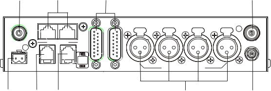
Figure 2-3
BTR-1 - Rear Panel
12.Relay Contacts: Normally Open. When activated it will close.
13.Receive Antenna Connector: TNC Female connector. The color dot near the connector must match the color of the antenna.
14.Auxiliary Connector: RJ-11 connector used to connect balanced auxiliary audio into and out of a base station.
15.CAN Bus: RJ-45 connectors used to connect a base station to a CAN type of communications bus.
16.4 WIRE Connector: RJ-11 connector used to connect balanced 4-W audio into and out of the base station.
17.Intercom Loop Thru: Two DB15 connectors used to loop 6 channels of intercom audio thru a base station.
18.Intercom Jacks: XLR intercom jacks to allow interfacing to the first four intercom ports via XLR connectors in addition to them being available at the DB15 connectors.
19.Power Connector: Input power jack that requires 12 to 15 Volts AC or DC at 1000 mA.
20.Transmit Antenna Connector: TNC Female connector. The color dot near the connector must match the color of the antenna.
2-2
Section
3
TR-1 Beltpack
Controls and Connections - Top Panel
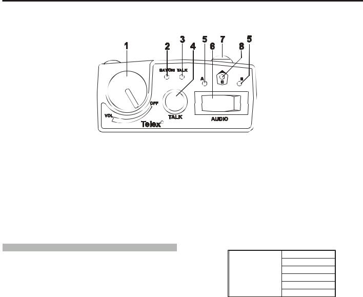
Figure 3-1
TR-1 Top Panel
1.On/Off & Volume Control: Turns the beltpack power on and controls headset volume.
2.BAT/O.M. Light:
Battery |
Light flashes on power up |
= Battery OK |
|
Light on continuously |
= Battery Low |
|
Light does not flash or come on |
= Battery Dead |
|
|
|
Overmodulation |
Light flashes on loudest speech |
= Gain OK |
|
Light flashes on all speech |
= Gain too high |
|
Light never flashes on loudest speech |
= Gain too Low |
|
|
|
5.A and B Lights: "A" light is on if selection switch in A position. "B" light is on if selection switch in B position.
6.Selection Switch: Switches between base station presets A or B.
7."C" Pushbutton: Press to enable the base station "C" presets.
Momentary
Latching
Selectable Modes: Quarterback
Button "C"
Off
Push-to-Talk
Latching Talk
3. Talk Light: LED is on when the talk button is active.
|
|
|
|
|
8. "C" Button Light: "C" light is on if "C" pushbutton ac- |
4. Talk button: Press to |
enable the audio path from the |
tive. |
|||
headset. |
|
|
|
|
|
|
|
|
|
|
|
|
Selectable Modes: |
|
Push-to-Talk |
|
|
|
TALK |
|
Push-to-Latch |
|
|
|
|
|
Off |
|
|
|
|
|
|
|
|
3-1
|
9 |
|
|
|
SET |
MENU |
14 |
10 |
|
13 |
|
|
|
||
11 |
PT PT |
|
15 |
|
TX TALK |
|
|
|
12 |
|
|
Controls and Connections - Rear Panel
Figure 3-2
TR-1 Rear Panel/Connector/Antennas
9.[MENU] and [SET] buttons: Used to select menus and set options on the LCD.
10.LCD (Liquid Crystal Display)
11.[UP] and [DOWN] buttons: Used to select beltpack options on the LCD.
12.Push-to-Talk/Push-to-Transmit Switch:
Push-to-Talk (PT TALK): The transmitter is always on. No audio is sent unless the talk button is active. Recommended position.
Push-to-Transmit (PT TX): The transmitter and audio paths are off except when the talk button is active.
13.Headset Connector: Male XLR connector for Telex units, Female XLR connector for RTS units.
14.Battery Latch: Press down to enable the battery pack to be released. While the latch is held down, slide the battery pack about 1/8 inch back, toward the latch, until it stops, then lift out.
15.Receive and Transmit Antennas: The antennas are screw type, ¼ wave, replaceable antennas. The color dot on the screw end of the antenna must match color dot on antenna receptacle.
Telex Units
(4) Headphone
(1) Microphone
Low (-)
Shield
(3) Headphone
(2) Microphone
High (+)
Audio
RTS Units
(1) Microphone
Shield (2) Microphone
Audio (+)
(4) Headphone |
(3) Headphone |
Low |
High (+) |
(1) Microphone
Shield 2) Microphone
Audio (+)
(3) Headphone
High (+)
(5) (4) Headphone
Low
Figure 3-3
Headset Jack Wiring
3-2

Section
4
Specifications
BTR-1
Specifications
Overall
RF Frequency Range . . . . . . . . . . . . . . . . . . . . . . . . . . . . . . . . . . 482 - 608 MHz, 614 - 746 MHz in 18 MHz TX and RX bands Power Requirements . . . . . . . . . . . . . . . . . . . . . . . . . . . . . . . . . . . . . . . . . . . . . . . . . . . . . . . . . . . . 12-15 Volts AC/DC @ 1 Amp Temperature Range. . . . . . . . . . . . . . . . . . . . . . . . . . . . . . . . . . . . . . . . . . . . . . . . . . . . . . . . . . . -4° F to 130° F (-20° C to 55° C) Dimensions. . . . . . . . . . . . . . . . . . . . . . . . . . . . . . . . . . . . . . . . . . . . 8.25” W x 1.72” H x 9.00” D (20.9 cm x 4.4 cm x 22.9 cm) Weight . . . . . . . . . . . . . . . . . . . . . . . . . . . . . . . . . . . . . . . . . . . . . . . . . . . . . . . . . . . . . . . . . . . . . . . . . . . . . . . 3 lbs 8 oz (1.59 kg) TX Antenna . . . . . . . . . . . . . . . . . . . . . . . . . . . . . . . . . . . . . . . . . . . . . . . . . . . . . . . . . ½ Wave (supplied), TNC Male Connector RX Antenna . . . . . . . . . . . . . . . . . . . . . . . . . . . . . . . . . . . . . . . . . . . . . . . . . . . . . . . . . ½ Wave (supplied), TNC Male Connector FCC ID: . . . . . . . . . . . . . . . . . . . . . . . . . . . . . . . . . . . . . . . . . . . . . . . . . . . . . . . . . . . . . . . . . . . . . . . . . . . . . . . . . . . . . B5DM519 Frequency Response . . . . . . . . . . . . . . . . . . . . . . . . . . . . . . . . . . . . . . . . . . . . . . . . . . . . . . . . . . . . . . . . . . . . . . . . 100Hz-4.0kHz Four Wire Input . . . . . . . . . . . . . . . . . . . . . . . . . . . . . . . . . . . . . . . . . . . . . . . . . . . . . . . . . . . . Level Adjustable (2 Vrms typical) Four Wire Output . . . . . . . . . . . . . . . . . . . . . . . . . . . . . . . . . . . . . . . . . . . . . . . . . . . . . . . . . . . Level Adjustable (2 Vrms typical) Telex Intercom. . . . . . . . . . . . . . . . . . . . . . . . . . . . . . . . Input/Output Level Adjustable (1 Vrms typical), Line impedance 300W
RTS Intercom . . . . . . . . . . . . . . . . . . . . . . . . . . . . . Input/Output Level Adjustable (0.775 Vrms typical), Line Impedance 200W
ClearCom® Intercom . . . . . . . . . . . . . . . . . . . . . . . . . . Input/Output Level Adjustable (1 Vrms typical), Line Impedance 200W
Auxiliary Input . . . . . . . . . . . . . . . . . . . . . . . . . . . . . . . . . . . . . . . . . . . . . . . . . . . . . . . . . . . . . Level Adjustable (2 Vrms typical) Auxiliary Output . . . . . . . . . . . . . . . . . . . . . . . . . . . . . . . . . . . . . . . . . . . . . . . . . . . Level Adjustable (2 Vrms typical into 600W) Microphone input sensitivity . . . . . . . . . . . . . . . . . . . . . . . . . . . . . . . . . . . . . . . . . . . . . . . . . . . . . . . . . . . . 10mV (200Ω Source) Local Headset Output . . . . . . . . . . . . . . . . . . . . . . . . . . . . . . . . . . . . . . . . . . . . . . . . . 200mW output into 150W (1% Distortion) Mute of Wire Income Port. . . . . . . . . . . . . . . . . . . . . . . . . . . . . . . . . . . . . . . . . . . . . . . . . . . . 100 dB (30kHz Low Pass Filtered)
Transmitter
Type. . . . . . . . . . . . . . . . . . . . . . . . . . . . . . . . . . . . . . . . . . . . . . . . . . . . . . . . . . . . . . . . . . Synthesized Transmitter, 720 channels Transmit Power . . . . . . . . . . . . . . . . . . . . . . . . . . . . . . . . . . . . . . . . . . . . . . . . . . . 50mW typical (High), 5 mW typical (Normal) Modulation Type . . . . . . . . . . . . . . . . . . . . . . . . . . . . . . . . . . . . . . . . . . . . . . . . . . . . . . . . . . . . . . . . . . . . . . . . . . . . . . . . . GMSK Deviation. . . . . . . . . . . . . . . . . . . . . . . . . . . . . . . . . . . . . . . . . . . . . . . . . . . . . . . . . . . . . . . . . . . . . . . Complies with FCC 74.861 RF Frequency Stability. . . . . . . . . . . . . . . . . . . . . . . . . . . . . . . . . . . . . . . . . . . . . . . . . . . . . . . . . . . . . . . . . . . . . . . . . . . . 0.005% Radiated Harmonics & Spurious . . . . . . . . . . . . . . . . . . . . . . . . . . . . . . . . . . . . . . . . . . . . . . . . . . . . Exceeds FCC specifications
Receiver
Type . . . . . . . . . . . . . . . . . . . . . . . . . . . . . . . . . . . . . . . . . . . . . . . . . . . . . Dual Conversion Superheterodyne, 720 channels each RF Sensitivity. . . . . . . . . . . . . . . . . . . . . . . . . . . . . . . . . . . . . . . . . . . . . . . . . . . . . . . . . . . . . . . . . . . . <0.8 µV for 12 dB SINAD IF Selectivity . . . . . . . . . . . . . . . . . . . . . . . . . . . . . . . . . . . . . . . . . . . . . . . . . . . . . . . . . . . . . . . . . . . . . . . . . . . . 3 dB at 230 kHz Image Rejection . . . . . . . . . . . . . . . . . . . . . . . . . . . . . . . . . . . . . . . . . . . . . . . . . . . . . . . . . . . . . . . . . . . . . . . . . . . 70 dB or better RF Frequency Stability. . . . . . . . . . . . . . . . . . . . . . . . . . . . . . . . . . . . . . . . . . . . . . . . . . . . . . . . . . . . . . . . . . . . . . . . . . . . 0.005% Distortion . . . . . . . . . . . . . . . . . . . . . . . . . . . . . . . . . . . . . . . . . . . . . . . . . . . . . . . . . . . . . . . . . . . . . . . . . . . . . . <1% at peak level S/N Ratio out to wired Intercom Ports . . . . . . . . . . . . . . . . . . . . . . . . . . . . . . . . . . . . . . . . . . . 80 dB (30kHz Low Pass Filtered)
4-1

TR-1
Specifications
RF Frequency Range . . . . . . . . . . . . . . . . . . . . . . . 482 - 608 MHz, 614-746 MHz in 18 MHz TX and RX bands Power Requirements. . . . . . . . . . . . . . . . . . . . . . . . . . . . . . . . . . . . . . . . 6 “AA” Cells Alkaline (NiMH optional) Current Draw . . . . . . . . . . . . . . . . . . . . . . . . . . . . . . . . . . . . . . . . . . . . . . . . . . . 190 mA (Push-to-Talk, Talk On) Temperature Range . . . . . . . . . . . . . . . . . . . . . . . . . . . . . . . . . . . . . . . . . . . . . . -4° F to 130° F (-20° C to 55° C) Dimensions . . . . . . . . . . . . . . . . . . . . . . . . . . . . . . . . . 3.75”W x 5.10”H x 1.65” D (9.5 cm x 12.9 cm x 4.2 cm) Weight . . . . . . . . . . . . . . . . . . . . . . . . . . . . . . . . . . . . . . . . . . . . . . . . . . . . . . 15 oz (425g) with alkaline batteries TX Antenna . . . . . . . . . . . . . . . . . . . . . . . . . . . . . . . . . . . . . . . . . . 1/4 Wave (supplied), Screw type, Replaceable RX Antenna. . . . . . . . . . . . . . . . . . . . . . . . . . . . . . . . . . . . . . . . . . 1/4 Wave (supplied), Screw type, Replaceable FCC ID: . . . . . . . . . . . . . . . . . . . . . . . . . . . . . . . . . . . . . . . . . . . . . . . . . . . . . . . . . . . . . . . . . . . . . . . . . B5DM520 Frequency Response . . . . . . . . . . . . . . . . . . . . . . . . . . . . . . . . . . . . . . . . . . . . . . . . . . . . . . . . . . . . 100Hz-4.0kHz Microphone input sensitivity. . . . . . . . . . . . . . . . . . . . . . . . . . . . . . . . . . . . . . . . . . . . . . . . . 7 mV (200Ω Source) Local Headset Output . . . . . . . . . . . . . . . . . . . . . . . . . . . . . . . . . . . . . 200 mW output into 150W (1% distortion)
Transmitter
Type . . . . . . . . . . . . . . . . . . . . . . . . . . . . . . . . . . . . . . . . . . . . . . . . . . . . . . . . . . . . . . . Synthesized, 720 channels Transmit Power . . . . . . . . . . . . . . . . . . . . 50 mW typical (High), 5 mW typical (Low), or auto-power switching Modulation Type . . . . . . . . . . . . . . . . . . . . . . . . . . . . . . . . . . . . . . . . . . . . . . . . . . . . . . . . . . . . . . . . . . . . . GMSK Deviation. . . . . . . . . . . . . . . . . . . . . . . . . . . . . . . . . . . . . . . . . . . . . . . . . . . . . . . . . . . Complies with FCC 74.861 RF Frequency Stability . . . . . . . . . . . . . . . . . . . . . . . . . . . . . . . . . . . . . . . . . . . . . . . . . . . . . . . . . . . . . . . . 0.005% Radiated Harmonics & Spurious . . . . . . . . . . . . . . . . . . . . . . . . . . . . . . . . . Meets or exceeds FCC specifications
Receiver
Type . . . . . . . . . . . . . . . . . . . . . . . . . . . . . . . . . . Dual Conversion Superheterodyne, Synthesized, 720 channels RF Sensitivity. . . . . . . . . . . . . . . . . . . . . . . . . . . . . . . . . . . . . . . . . . . . . . . . . . . . . . . . <0.8 µV for 12 dB SINAD IF Selectivity. . . . . . . . . . . . . . . . . . . . . . . . . . . . . . . . . . . . . . . . . . . . . . . . . . . . . . . . . . . . . . . . . 3 dB at 230 kHz Image Rejection . . . . . . . . . . . . . . . . . . . . . . . . . . . . . . . . . . . . . . . . . . . . . . . . . . . . . . . . . . . . . . . 70 dB or better RF Frequency Stability . . . . . . . . . . . . . . . . . . . . . . . . . . . . . . . . . . . . . . . . . . . . . . . . . . . . . . . . . . . . . . . . 0.005% Distortion . . . . . . . . . . . . . . . . . . . . . . . . . . . . . . . . . . . . . . . . . . . . . . . . . . . . . . . . . . . . . . . . . . <1% at peak level
S/N Ratio in From wired Intercom Ports . . . . . . . . . . . . . . . . . . . . . . . . . . . . . . . . . . . . . . . 80 dB (30kHz Low Pass Filtered)
4-2

Section
5
Initial Equipment Set-Up
Unpacking
Unpack your RadioCom™ system. Below are the items that should come with your base station and each belt pack. Contact the shipper or your dealer immediately if anything is damaged or missing.
BTR-1
Quantity |
Description |
|
|
1 |
BTR-1 Base Station |
|
|
1 |
Operating Instructions |
|
|
1 |
In-Line Power Supply |
|
|
2 |
Antennas (one Transmit, one Receive) |
|
|
1 |
Limited Warranty Sheet |
|
|
4 |
Rubber Feet |
|
|
1 |
Gain Adjust Plastic Screwdriver |
|
|
1 |
Two Terminal Plug (for Relay) |
|
|
2 |
Large Phillips Pan head Screw for Rack Mounting |
|
|
2 |
Small Phillips Flathead Screw for rack Mounting |
|
|
1 |
Single Unit Rack Mount Bracket |
|
|
1 |
Dual Units (Side by Side) Middle Rack Mount Bracket |
|
|
1 |
Rack Mount Side Bracket |
|
|
1 |
Interconnect Cable (15 pin to 15 pin) |
|
|
|
|
TR-1
Quantity |
Description |
|
|
1 |
TR-1 Beltpack with Antennas |
|
|
1 |
Instruction Card |
|
|
1 |
Battery Pack |
|
|
1 |
Limited Warranty Sheet |
|
|
|
|
5-1
Rack Mounting
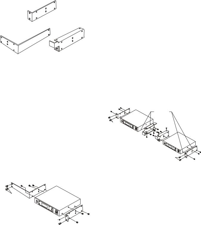
The rack mounting brackets come with each BTR-1. These brackets may be used to mount a single base station in a 19" wide rack or mount two base stations side by side in a rack. Figure 5-1 shows the three brackets that come with a base sta- tion.
DOUBLE UNIT RACK MOUNT BRACKET
SINGLE UNIT RACK MOUNT BRACKET |
RACK MOUNT MIDDLE BRACKET |
Figure 5-1
Rack Mount Brackets
Rack Mounting a Single Base Station
1.Remove the four pan head screws (two on each side) closest to the front panel.
2.Place the double unit side bracket on the side of the base station you wish closest to the edge of the rack.
3.Replace the two pan head screws and use a third pan head screw (2 supplied with base station) to screw into the upper middle location of the bracket.
4.Place the single unit rack mount bracket on the other side of the base station.
5.Replace the two pan head screws and the other pan head screw that came with the base to secure the bracket. Screw the third screw into the upper middle hole of the bracket.
6.Use the rack mount screws (not supplied) to secure the unit to the rack.
NOT
SUPPLIED
NOT
SUPPLIED 

Figure 5-2
Rack Mounting of a Single Unit
Rack Mounting Two Base Stations
Side-by-Side
1.Remove the four pan head screws (two on each side) closes to the front panel.
2.Place the double unit side brackets on the sides of the base stations you wish closest to the edge of the rack.
3.Replace the two pan head screws and use a third pan head screw (2 supplied with base station) to screw into the upper middle location of the rack mount middle bracket.
4.Place the dual bracket on the other sides of the base stations. Make sure the bracket is flipped so the front bend is toward the front of the base station. As you face the rack, the right base station will have the middle bracket front bend high and left base station will have the bend low.
5.Replace the two pan head screws and the other pan head screw into the upper middle hole of each bracket.
6.Use the four flat head screws (2 supplied with base station) to secure the top and bottom of the middle brackets together.
7.Use rack mount screws (not supplied) to secure the unit to the rack.
REMOVE SCREWS
(TYPICAL 4 SIDES)
NOT
SUPPLIED
NOT
SUPPLIED
Figure 5-3
Rack Mounting Two Base Units Side-by-Side
5-2
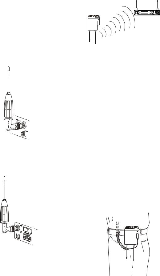
Antenna Connection
The base station is supplied with two (2) antennas. One 1/2-wave antenna for Transmit and one 1/2-wave for Receive. The antennas have TNC male connectors.
The frequency range of the antennas should match the receiver and transmitter of the base station. Match the color code on the antenna with the color code on the base station.
Attach the transmit 1/2-wave antenna to the antenna input re- ceptacle labeled “TRAN” on the right side of the rear panel. The antenna should be vertically aligned.
Figure 5-4
Attaching Transmit 1/2-Wave Antenna
Attach the receive 1/2-wave antenna to the antenna input re- ceptacle labeled “RCV” on the left side of the rear panel. The antenna should be vertically aligned.
Figure 5-5
Attaching Receive 1/2-Wave Antenna
Antenna Polarization
The Telex Wireless Intercom System is “Vertically Polarized”. This means both the transmitting and receiving antennas should operate in the vertical position.
xeleT
Telex
RadioComTM
TR-1
ANTENNAS SHOULD BE VERTICAL
Figure 5-6
Vertically Polarized Antennas
Distance between Antennas
The distance between the base station’s receive and transmit antennas is not adjustable when the antennas are connected di- rectly on the back of the unit.
The antennas can be remoted for better signal path. A Telex coax assembly with remote antennas may be required. See “Accessory and Replacement Parts” section for ordering infor- mation.
NOTE: If your base station is to be located in a shielded rack mount enclosure or other poor RF location, you must remote the 1/2-wave antennas with coax assemblies. See “Accessories and Replacement Parts” section for remote mounting hard- ware.
Antenna Placement
Proper antenna placement probably has the most effect on your TELEX Wireless Intercom System’s overall perfor- mance. The following suggestions will result in optimum per- formance.
Proper placement of the beltpack can be critical. The antennas should be in the open. Bending the antennas up and placing the beltpack in a pocket, etc., will reduce system distance.
It is suggested that the unit be worn on the belt or pocket with both antenna’s vertical for best operating range and perfor- mance.
xeleT
Telex
TM
RadioCom
TR-1
Figure 5-7
Proper Dressing of the Antennas
5-3
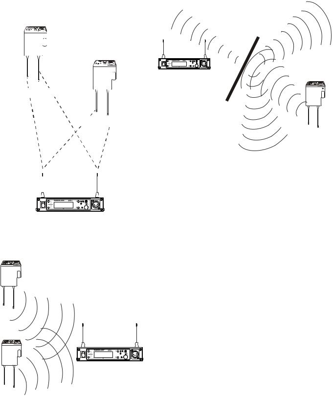
Keep the distance between the base station and the beltpacks as short as possible. The greater the distance, the weaker the signal. Make sure the “signal paths” between the base station and beltpacks are unobstructed. You should be able to visibly locate the base station antennas at all times for best perfor- mance.
xeleT
Telex
Attempting to operate the wireless intercom system through or around walls, ceilings, metal objects, etc. will reduce system range and performance.
xeleT
Telex
xeleT
Telex
700 FEET
RadioComTM
TR-1
100 FEET
Figure 5-8
Distance Between base station and beltpack
xeleT
Telex
RadioComTM
TR-1
xeleT
Telex
TM
RadioCom
TR-1
Figure 5-10
Operating System Near Obstructions
DO NOT - mount the base station 1/2-wave antennas on, or next to metal, such as beams, walls with metal studs, equip- ment racks, etc. This also applies to the antennas when assem- bled directly to the Base Station. This will “detune” the antennas which can result in noise or loss of RF signal at the base station.
Keeping the distance from the base station and beltpack as short, and unobstructed as possible will produce the most reli- able performance.
The base station is supplied with two antennas. This should provide satisfactory system performance in most applications. System range can be enhanced by remoting the 1/2-wave an- tennas.
Figure 5-9
Keeping Site Clear to Antennas
5-4
 Loading...