


 Loading...
Model IP-223
Remote Adapter Panel
Technical Manual
up to and including version 4.100
803641 Rev K |
07/2008 |
PROPRIETARY NOTICE
The product information and design disclosed herein were originated by and are the property of Telex Communications, Inc. Telex reserves all patent, proprietary design, manufacturing, reproduction, use and sales rights thereto, and to any article disclosed therein, except to the extent rights are expressly granted to others.
COPYRIGHT NOTICE
Copyright 2008 by Telex Communications, Inc. All rights reserved. Reproduction, in whole or in part, without prior written permission from Telex is prohibited.
WARRANTY NOTICE (LIMITED)
All Telex manufactured signaling products are guaranteed against malfunction due to defects in materials and workmanship for three (3) years, beginning at the original date of purchase.If such a malfunction occurs, the product be repaired or replaced (at our option) without charge during the three (3) year period, if delivered to the Telex factory. Warranty does not extend to damage due to improper repairs, finish or appearance items, or malfunction due to abuse or operation under other than the specified conditions, nor does it extend to incidental or consequential damages. Some states do not allow the exclusion or limitation of incidental or consequential damages. Some states do not allow the exclusion or limitation of incidental or consequential damages, so the above limitation may not apply to you. This warranty gives the customer specific legal rights, and there may be other rights which vary from state to state.
FACTORY SERVICE CENTER
Factory Service Center
Telex Communications, Inc.
Radio Dispatch Products
8601 East Cornhusker Highway
Lincoln, Nebraska, 68507
PHONE NUMBERS |
|
Sales: |
|
Phone ................................................................... |
(800) 752-7560 |
Fax........................................................................ |
(402) 467-3279 |
E-mail........................................... |
TelexDispatch@us.bosch.com |
Customer Service Repair: ................................................. |
(800) 553-5992 |
Technical Support: |
|
Phone ................................................................... |
(800) 898-6723 |
E-mail ........................ |
TelexDispatchtechsupport@us.bosch.com |
Web .................................................................................. |
www.telex.com |
CLAIMS |
|
No liability be accepted for damages directly or indirectly arising from the use of our materials or from any other causes. Our liability shall be expressly limited to replacement or repair of defective materials.

Table
of
Contents
OVERVIEW..................................................... |
13 |
Operating Modes .................................................. |
13 |
FEATURES ................................................................... |
14 |
IP-223 ACCESSORIES .................................................. |
15 |
IP-223 Specifications ............................................ |
16 |
Front Panel ........................................................... |
16 |
TEST AND ADJUSTMENT POINTS .................................. |
16 |
HANDSET JACK ........................................................... |
17 |
IC BUTTON ................................................................. |
17 |
LCD DISPLAY ............................................................. |
17 |
LINE BUTTON ............................................................. |
18 |
TX LED ..................................................................... |
18 |
LNK LED .................................................................. |
18 |
Back Panel ............................................................ |
19 |
10/100 ETHERNET CONNECTOR .................................. |
19 |
SERIAL CONNECTOR ................................................... |
19 |
RADIO 1 AND RADIO 2 (LINE 1 AND LINE 2) |
|
CONNECTORS .............................................................. |
20 |
POWER CONNECTION .................................................. |
20 |
COMMUNICATIONS SYSTEM DESIGN .... |
23 |
Network Requirements .......................................... |
23 |
BANDWIDTH ................................................................ |
23 |
MULTICAST ................................................................. |
23 |
INTERNET GROUP MANAGEMENT PROTOCOL (IGMP) 24 |
|
NETWORK PERFORMANCE ........................................... |
24 |
INSTALLATION AND LEVEL SETTINGS . 25 |
|
Local/Radio Connections ..................................... |
25 |
JUMPER POSITIONS ..................................................... |
25 |
TX AUDIO CONNECTION ............................................. |
27 |
RX AUDIO CONNECTION ............................................. |
27 |
COR (CARRIER OPERATED RELAY) I/O |
|
(INPUT/OUTPUT) ........................................................ |
28 |
PTT CONNECTION ...................................................... |
28 |
MONITOR CONNECTION .............................................. |
28 |
R1 AND R2 RELAYS ..................................................... |
28 |
DIGITAL I/O ............................................................... |
29 |
CTCSS (CONTINUOUS TONE CODED SQUELCH SYSTEM) |
|
CONNECTION ............................................................. |
29 |
Tone/Console Operation ....................................... |
29 |
2-/4-WIRE JUMPER SETTINGS ..................................... |
29 |
TX SIDE SETTINGS ..................................................... |
29 |
LOCAL PTT I/O ......................................................... |
30 |
CROSS MUTE I/O ....................................................... |
30 |
SUPERVISORY I/O ....................................................... |
30 |
Level Adjustments ................................................. |
30 |
GENERAL ALIGNMENT ................................................ |
31 |
RADIO/LINE TX LEVEL ............................................... |
31 |
RADIO/LINE RX LEVEL ............................................... |
31 |
LINE TX MONITOR LEVEL (TONE AND CONSOLE MODE |
|
ONLY) ......................................................................... |
31 |
CTCSS LEVEL ........................................................... |
32 |
Frequency Decoding ............................................. |
32 |
SETUP INFORMATION ................................ |
33 |
Setting the IP Address Information ...................... |
33 |
USING HYPERTERMINAL ............................................. |
34 |
Accessing IP-223 Web Browser Configuration |
|
Windows ................................................................ |
39 |
IP-223 Web Setup Windows Standards ................ |
40 |
LINKS ......................................................................... |
40 |
Welcome Window ................................................. |
42 |
Basic Ethernet Setup Window ............................... |
43 |
SERIAL NUMBER FIELD .............................................. |
43 |
MAC ADDRESS .......................................................... |
43 |
USE DHCP SERVER CHECK BOX ............................... |
44 |
UNIT IP ADDRESS FIELD ............................................ |
44 |
SUBNET MASK FIELD ................................................. |
44 |
GATEWAY ADDRESS FIELD ......................................... |
44 |
DNS (DOMAIN NAME SERVER) NUMBER 1–3 FIELDS . 44 |
|
PACKET DELAY BEFORE PLAYBACK FIELD ................. |
44 |
QOS (QUALITY OF SERVICE): PRECEDENCE BITS |
|
FIELD ........................................................................ |
44 |
QOS: D, T, AND R (DELAY, THROUGHPUT, AND |
|
RELIABILITY) BITS FIELD ............................................ |
45 |
LOCAL COMPUTER IP ADDRESS 1-10 FIELDS ............ |
45 |
SUBMIT BUTTON ......................................................... |
46 |
General Gain Setup ............................................. |
47 |
HANDSET MIC GAIN DROP DOWN MENU .................... |
47 |
HANDSET SIDETONE GAIN DROP DOWN MENU ........... |
47 |
RECEIVE GAIN DROP DOWN MENU ............................ |
47 |
TRANSMIT GAIN DROP DOWN MENU .......................... |
48 |
CTCSS GAIN DROP DOWN MENU .............................. |
48 |
TX VOICE GAIN FIELD ............................................... |
48 |
SUBMIT BUTTON ......................................................... |
48 |
Multicast Address Setup Window ........................ |
49 |
LINE NUMBER FIELD .................................................. |
49 |
ENABLE VIA ETHERNET CHECK BOX ........................... |
49 |
LINE TYPE DROP DOWN MENU .................................. |
50 |
LINE NAME FIELD ...................................................... |
50 |
RX MCAST ADDRESS FIELD ........................................ |
50 |
RX PORT FIELD .......................................................... |
51 |
TX GROUP PORT FIELD ............................................. |
51 |
TTL FIELD ................................................................. |
51 |
VOCODER TYPE DROP DOWN MENU .......................... |
52 |
ENABLE CHECK BOX .................................................. |
52 |
LINE NAME FIELD ...................................................... |
52 |
MULTICAST ADDRESS FIELD ....................................... |
52 |
OUTGOING PORT FIELD ............................................. |
53 |
TTL FIELD ................................................................. |
53 |
ENABLE CHECK BOX .................................................. |
53 |
NAME FIELD ............................................................... |
53 |
MULTICAST ADDRESS FIELD ....................................... |
53 |
INCOMING PORT FIELD .............................................. |
53 |
OUTGOING PORT FIELD ............................................. |
53 |
TTL FIELD ................................................................. |
53 |
ENABLE CHECK BOX .................................................. |
53 |
VOCODER TYPE DROP DOWN MENU .......................... |
54 |
LINE NAME FIELD ...................................................... |
54 |
MCAST ADDRESS FIELD .............................................. |
54 |
PORT FIELD ................................................................ |
54 |
TTL FIELD ................................................................. |
54 |
SUBMIT BUTTON ......................................................... |
54 |
Per Line Setup Window ........................................ |
55 |
Per Line Setup Window— |
|
Local, Tone, and Console Mode Configuration .. 56 |
|
LINE 1 BUTTON .......................................................... |
56 |
LINE 2 BUTTON .......................................................... |
57 |
SUBMIT BUTTON ......................................................... |
57 |
LINE MODE STATUS FIELD ......................................... |
57 |
PORT ENABLED CHECK BOX ....................................... |
57 |
ALWAYS ON RADIO BUTTON ....................................... |
57 |
ON WITH PTT RADIO BUTTON ................................... |
58 |
TAPE OUTPUT RADIO BUTTON .................................... |
58 |
TX DELAY FIELD ........................................................ |
58 |
RX DELAY FIELD ........................................................ |
58 |
SQUELCH TAIL DELAY FIELD ...................................... |
58 |
JUMP TO ENTRY DROP DOWN MENU ......................... |
58 |
UPDATE BUTTON ........................................................ |
58 |
TONE ENABLE CHECK BOX ......................................... |
59 |
RELAY DROP DOWN MENU ......................................... |
59 |
RELAY GROUP DROP DOWN MENU ............................. |
59 |
RELAY TIME (MS) FIELD ............................................. |
59 |
DIGITAL OUTPUT FIELD - LOCAL MODE ONLY ........... |
60 |
CTCSS FREQ FIELD - LOCAL MODE ONLY ................. |
60 |
CTCSS DEFAULT CHECK BOX - LOCAL MODE ONLY .60 |
|
SYSTEM FIELD - LOCAL MODE .................................... |
60 |
CHAN FIELD - LOCAL MODE ....................................... |
60 |
LAM LEVEL FIELD ..................................................... |
61 |
LAM TIME FIELD ....................................................... |
61 |
OPTIONS ..................................................................... |
62 |
Supervisor Check Box ........................................... |
62 |
Cross Mute Check Box .......................................... |
62 |
Full Duplex Check Box ......................................... |
62 |
RxAGC Check Box................................................ |
62 |
Hi-Pass RX Check Box.......................................... |
62 |
Pre-Emphasize TX Check Box .............................. |
62 |
TX Monitor Check Box ......................................... |
62 |
2-Wire Check Box ................................................. |
63 |
Parallel Console Check Box .................................. |
63 |
PTT Notch Filter Check Box ................................. |
63 |
PTT TIMEOUT FIELD .................................................. |
63 |
Serial Port Mode Drop Down Menu...................... |
63 |
Serial Port Params Drop Down Menu ................... |
64 |
FleetSync Decode Check Box |
|
(Tone and Local Modes)........................................ |
65 |
FleetSync Encode Check Box (Local Mode Only) 66 |
|
MDC Decode Check Box |
|
(Tone and Local Modes)........................................ |
66 |
MDC Encode Check Box....................................... |
66 |
Tone Type Drop Down Menu................................ |
66 |
ANI Suffix Field .................................................... |
67 |
Digit Duration Field............................................... |
67 |
Interdigit Duration Field ........................................ |
67 |
Pause Duration Field.............................................. |
67 |
Preamble Duration Field ........................................ |
67 |
Group Digit Field................................................... |
67 |
Repeat Digit Field .................................................. |
67 |
ANI Decoder # Field.............................................. |
67 |
ANI Call Type Drop Down Menu ......................... |
68 |
ANI Call Format Field ........................................... |
68 |
Per Line Setup Window— |
|
Phone Mode Configuration ................................. |
69 |
Auto Answer Field................................................. |
69 |
Auto Disconnect Time Field.................................. |
69 |
TX DELAY FIELD ........................................................ |
69 |
RX DELAY FIELD ........................................................ |
70 |
LAM LEVEL FIELD ..................................................... |
70 |
LAM TIME FIELD ....................................................... |
70 |
Mic Click Call Enabled Check Box....................... |
70 |
Number of Clicks Field.......................................... |
70 |
Time Between Clicks Field.................................... |
70 |
Click Dial String Field ........................................... |
70 |
Click Dial Timeout Field ....................................... |
71 |
Relay Closure......................................................... |
71 |
R1 - Ring Check Box.......................................... |
71 |
R2 - OffHook Check Box ................................... |
72 |
Rx AGC Enabled Check Box ................................ |
72 |
Keep Alive Digits Enabled Check Box ................. |
72 |
Star/Pound Keying Enabled Check Box ................ |
72 |
Detect Tones Enabled Check Box ......................... |
72 |
Hook Flash Time Field .......................................... |
72 |
Network Call Timeout Field .................................. |
72 |
Station ID Field...................................................... |
72 |
Busy Channel Lockout Check Box........................ |
72 |
C550 Operation Enabled Check Box..................... |
73 |
RP251 Operation Enabled Check Box................... |
73 |
RP251 Access Digits Field .................................... |
73 |
RP251 Connect Digits Field .................................. |
73 |
SERIAL PORT MODE DROP DOWN MENU .................... |
73 |
SERIAL PORT PARAMETERS DROP DOWN MENU .......... |
73 |
FleetSync Decode Check Box ............................... |
75 |
MDC Decode Check Box ...................................... |
75 |
Tone Type Drop Down Menu................................ |
75 |
ANI Suffix Field .................................................... |
75 |
Digit Duration Field............................................... |
75 |
Interdigit Duration Field ........................................ |
76 |
Pause Duration Field.............................................. |
76 |
Preamble Duration Field ........................................ |
76 |
Group Digit Field................................................... |
76 |
Repeat Digit Field .................................................. |
76 |
ANI Decoder Field................................................. |
76 |
ANI Call Type Drop Down Menu ......................... |
76 |
ANI Call Format Field ........................................... |
77 |
Per Line Setup Window— |
|
iDEN Radio Configuration ................................... |
77 |
TX DELAY FIELD ........................................................ |
78 |
RX DELAY FIELD ........................................................ |
78 |
SQUELCH TAIL DELAY FIELD ...................................... |
78 |
THE RANGE FOR THIS FIELD IS 0 TO 5000. .................. |
79 |
JUMP TO ENTRY DROP DOWN MENU .......................... |
79 |
UPDATE BUTTON ........................................................ |
79 |
TONE ENABLE CHECK BOX ......................................... |
79 |
RELAY DROP DOWN MENU ......................................... |
80 |
RELAY GROUP DROP DOWN MENU ............................. |
80 |
RELAY TIME (MS) FIELD ............................................. |
80 |
CALL TYPE DROP DOWN MENU .................................. |
81 |
IDEN NUMBER FIELD ................................................. |
81 |
LAM LEVEL FIELD ..................................................... |
82 |
LAM TIME FIELD ....................................................... |
82 |
Full Duplex Check Box ......................................... |
82 |
RxAGC Check Box................................................ |
82 |
Hi-Pass RX Check Box.......................................... |
82 |
Pre-Emphasize TX Check Box .............................. |
82 |
F1 Last Call Check Box (iDEN Mode only) ......... |
83 |
PTT Notch Filter Check Box ................................. |
83 |
Busy Channel Lockout Check Box........................ |
83 |
PTT TIMEOUT FIELD .................................................. |
83 |
SERIAL PORT MODE DROP DOWN MENU .................... |
83 |
SERIAL PORT PARAMETERS DROP DOWN MENU .......... |
83 |
Per line Setup Window— |
|
Tetra Radio Configuration .................................. |
84 |
JUMP TO ENTRY DROP DOWN MENU ......................... |
84 |
UPDATE BUTTON ....................................................... |
84 |
TONE ENABLE CHECK BOX ........................................ |
84 |
RELAY DROP DOWN MENU ........................................ |
85 |
RELAY GROUP DROP DOWN MENU ............................ |
85 |
RELAY TIME (MS) FIELD ............................................. |
85 |
TYPE DROP DOWN MENU .......................................... |
85 |
ISSI/GSSI NUMBER FIELD ......................................... |
86 |
TX DELAY FIELD ....................................................... |
87 |
RX DELAY FIELD ....................................................... |
87 |
LAM LEVEL FIELD ..................................................... |
88 |
LAM TIME FIELD ....................................................... |
88 |
Full Duplex Check Box......................................... |
88 |
RxAGC Check Box............................................... |
88 |
Hi-Pass RX Check Box ......................................... |
88 |
Pre-Emphasize TX Check Box ............................. |
89 |
PTT Notch Filter Check Box ................................ |
89 |
Busy Channel Lockout Check Box ....................... |
89 |
PTT TIMEOUT FIELD ................................................. |
89 |
SERIAL PORT MODE DROP DOWN MENU ................... |
89 |
SERIAL PORT PARAMETERS DROP DOWN MENU ......... |
89 |
Save to EEPROM Window ................................... |
90 |
SAVE PARAMETERS BUTTON ....................................... |
90 |
RESET IP-223 BUTTON .............................................. |
90 |
Account Setup Window ........................................ |
91 |
Admin System Account ........................................ |
91 |
User System Account ............................................ |
91 |
Enable Check Box................................................. |
92 |
Username Display Column ................................... |
92 |
Password Field ...................................................... |
92 |
New Password Field.............................................. |
92 |
Confirm Password Field........................................ |
93 |
Edit Button ............................................................ |
93 |
Save Button ........................................................... |
93 |
Submit Button ....................................................... |
93 |
Delete, Username, Password, New Password, |
|
Confirm Password Display Columns .................... |
93 |
Delete Button......................................................... |
94 |
Add New User Button ........................................... |
94 |
Reset System Parameters Button........................... |
94 |
Edit System Accounts Window ............................. |
94 |
Add New User Window ........................................ |
96 |
Username Field ..................................................... |
96 |
Password Field ...................................................... |
96 |
Confirm Password Field........................................ |
96 |
Additional Feature Check Box.............................. |
97 |
Save To EEPROM Check Box.............................. |
97 |
Welcome Page Check Box.................................... |
97 |
Account Setup Check Box .................................... |
97 |
Basic Ethernet & Multicast Setup Check Box ...... |
97 |
Clone Console & Pass Change Check Box........... |
97 |
CRP Setup & PIN Table Check Box..................... |
97 |
General Gain Check Box ....................................... |
97 |
Per Line Setup Check Box..................................... |
97 |
Tone Freq & Durations Check Box ....................... |
98 |
Submit Button........................................................ |
98 |
Cancel Button ........................................................ |
98 |
Edit Created Accounts Window ........................... |
99 |
Additional Feature Setup Window ..................... |
100 |
Clone Console Window ...................................... |
101 |
Crosspatch Setup Window ................................. |
102 |
Enable Line – Line Check Box............................ |
103 |
Start Patch FTone Drop Down Menu .................. |
103 |
Stop Patch FTone Drop Down Menu .................. |
103 |
RCP Enable Check Box....................................... |
103 |
Dialing Digits Field ............................................. |
103 |
Interdigit Time Field............................................ |
103 |
Beep Dly Field..................................................... |
103 |
Patch Timeout Field............................................. |
104 |
Global Field ......................................................... |
104 |
Drop All Field...................................................... |
104 |
RCP TABLES ............................................................. |
104 |
JUMP TO ENTRY DROP DOWN MENU AND |
|
GO BUTTON .............................................................. |
104 |
Entry Field ........................................................... |
104 |
Add String Field .................................................. |
104 |
Delete String Field............................................... |
105 |
Mode Drop Down Menu...................................... |
105 |
Phone Field (DIAL option only).......................... |
105 |
#1 or #2 Drop Down Menu |
|
(XPATCH option only) ....................................... |
105 |
IP Address Field (XPATCH option only) ........... |
106 |
Rx Multicast Field (DLVOIP option only).......... |
106 |
Rx Port Field (DLVOIP option only) .................. |
106 |
Tx Multicast Field (DLVOIP option only).......... |
106 |
Tx Port Field (DLVOIP option only) .................. |
106 |
COMMAND BUTTONS ................................................ |
106 |
Prev 10 Button ..................................................... |
106 |
Next 10 Button..................................................... |
107 |
CRP PIN Table Window .................................... |
108 |
JUMP TO ENTRY DROP DOWN MENU AND |
|
GO BUTTON .............................................................. |
109 |
SUBMIT BUTTON ....................................................... |
109 |
PIN ENABLE CHECK BOX ......................................... |
109 |
ENTRY FIELD ............................................................ |
109 |
PIN FIELD ................................................................ |
109 |
SUBMIT BUTTON ....................................................... |
109 |
Prev 30 Entries Button......................................... |
110 |
Next 30 Entries Button ........................................ |
110 |
Pass Change Window ........................................ |
111 |
Tone Frequency & Durations Window .............. |
112 |
MONITOR FREQUENCY FIELD ................................... |
112 |
PTT FREQUENCY DROP DOWN MENU ...................... |
113 |
GUARD TONE DURATION FIELD ................................ |
113 |
GUARD TONE MAGNITUDE FIELD ............................. |
113 |
HOLD TONE MAGNITUDE FIELD ............................... |
113 |
HOLD TONE HANGTIME FIELD .................................. |
113 |
FUNCTION TONE DURATION FIELD ........................... |
114 |
FUNCTION TONE MAGNITUDE FIELD ........................ |
114 |
FTONE 1-16 FREQUENCY FIELDS ............................. |
114 |
UPDATE FIRMWARE ................................. |
117 |
Update Firmware ............................................... |
117 |
INSTALL TSM ............................................................ |
117 |
DOWNLOAD TELEX FIRMWARE .................................. |
119 |
UPDATE FIRMWARE TOOL WINDOW .......................... |
120 |
File Field .............................................................. |
120 |
Device Type Field................................................ |
120 |
Firmware Version Field ....................................... |
120 |
Left Navigation Pane ........................................... |
120 |
Manual Entry Field .............................................. |
121 |
Username Field .................................................... |
121 |
Password Field ..................................................... |
121 |
Write Firmware Button ........................................ |
121 |
Close Button......................................................... |
121 |
UPLOAD VOIP HARDWARE FIRMWARE ...................... |
121 |
IP-223 SETTINGS - QUICK REFERENCE 123 |
|
I/O Connectors ................................................... |
123 |
Adjustments ........................................................ |
123 |
Jumper Settings .................................................. |
124 |
PCB 750743 OR PCB 750630 REVISION F ............... |
124 |
PCB 750743 OR PCB 750630 REVISION |
|
C, D, E, AND F ........................................................ |
124 |
PCB 750630 REVISION A ......................................... |
124 |
Jumper Locations ............................................... |
125 |
Additional Resources ......................................... |
127 |
CTCSS Tone Frequency Table ........................... |
131 |
Digital Output Table .......................................... |
133 |
Tone Frequency Table ....................................... |
135 |

List
of
Figures
FIGURE 1. Local and Tone Mode Connections ................................................................................................. |
13 |
FIGURE 2. Console Mode Connection ............................................................................................................... |
14 |
FIGURE 3. IP-223 Front Panel .......................................................................................................................... |
16 |
FIGURE 4. IP-223 Case Top Test Points ........................................................................................................... |
17 |
FIGURE 5. IP-223 Back Panel ........................................................................................................................... |
19 |
FIGURE 6. DB25 Connector Pinout Configuration ........................................................................................... |
21 |
FIGURE 7. Jumper Positions .............................................................................................................................. |
25 |
FIGURE 8. IP-223 PCB Assembly ...................................................................................................................... |
26 |
FIGURE 9. HyperTerminal Navigation .............................................................................................................. |
34 |
FIGURE 10. Com Terminal Setup Windows ....................................................................................................... |
35 |
FIGURE 11. HyperTerminal Window Password ................................................................................................ |
36 |
FIGURE 12. HyperTerminal Factory Setup Options – Serial Port Access Window .......................................... |
37 |
FIGURE 13. Connect to [IP Address] Window .................................................................................................. |
39 |
FIGURE 14. IP-223 Links ................................................................................................................................... |
40 |
FIGURE 15. Welcome Window ........................................................................................................................... |
42 |
FIGURE 16. Basic Ethernet Setup Window ........................................................................................................ |
43 |
FIGURE 17. General Gain Setup Window .......................................................................................................... |
47 |
FIGURE 18. Multicast Address Setup.................................................................................................................. |
49 |
FIGURE 19. Line Type Drop Down Menu .......................................................................................................... |
50 |
FIGURE 20. Vocoder Type Drop Down Menu ................................................................................................... |
52 |
FIGURE 21. Vocoder Type Drop Down Menu ................................................................................................... |
54 |
FIGURE 22. Per Line Setup - Local, Tone, and Console Modes (view 1) .......................................................... |
56 |
FIGURE 23. Relay Drop Down Menu—Per Line Setup ..................................................................................... |
59 |
FIGURE 24. Per Line Setup - Local Tone and Console Modes (view 2) ............................................................ |
61 |
FIGURE 25. Serial Port Drop Down Menu - Local Mode ................................................................................. |
64 |
FIGURE 26. Serial Port Params Drop Down Menu - Normal Mode ................................................................. |
64 |
FIGURE 27. Per Line Setup - Local, Tone, and Console Mode (view 3) ........................................................... |
65 |
FIGURE 28. Tone Type Drop Down Menu ......................................................................................................... |
66 |
FIGURE 29. ANI Call Type Drop Down Menu-Per Line Setup ......................................................................... |
68 |
FIGURE 30. Per Line Setup - Phone Mode (view 1) .......................................................................................... |
69 |
FIGURE 31. Per Line Setup - Phone Mode (view 2) .......................................................................................... |
71 |
FIGURE 32. Serial Port Params Drop Down Menu - Phone Mode ................................................................... |
74 |
FIGURE 33. Per Line Setup - Phone Mode (view 3) .......................................................................................... |
74 |
FIGURE 34. Tone Type Drop Down Menu ......................................................................................................... |
75 |
FIGURE 35. ANI Call Type Drop Down Menu .................................................................................................. |
77 |
FIGURE 36. Per Line Setup - iDEN Radio Mode (view 1) ................................................................................. |
78 |
FIGURE 37. Relay Drop Down Menu-Per Line Setup ....................................................................................... |
80 |
FIGURE 38. Call Type Drop Down Menu - iDEN Mode ................................................................................... |
81 |
FIGURE 39. Per Line Setup - iDEN Mode (view 2) ........................................................................................... |
81 |
FIGURE 40. Per Line Setup - Tetra Mode (view 1) ........................................................................................... |
84 |
FIGURE 41. Relay Drop Down Menu ................................................................................................................ |
85 |
FIGURE 42. Type Drop Down Menu - Tetra Mode ........................................................................................... |
86 |
FIGURE 43. Per lIne Setup - Tetra Mode (view 2) ............................................................................................ |
87 |
FIGURE 44. Save to EEPROM .......................................................................................................................... |
90 |
FIGURE 45. Reset IP-223 .................................................................................................................................. |
91 |
FIGURE 46. Account Setup ................................................................................................................................ |
92 |
FIGURE 47. Edit System Account ...................................................................................................................... |
94 |
FIGURE 48. Success Message ............................................................................................................................ |
95 |
FIGURE 49. Add New User—Account Setup ..................................................................................................... |
96 |
FIGURE 50. Edit Created Account—Account Setup .......................................................................................... |
99 |
FIGURE 51. Additional Feature Access ........................................................................................................... |
100 |
FIGURE 52. Clone System Parameters ............................................................................................................ |
101 |
FIGURE 53. Crosspatch Setup ......................................................................................................................... |
102 |
FIGURE 54. Crosspatch Setup - Mode Drop Down Menu .............................................................................. |
105 |
FIGURE 55. #1 or #2 Drop Down Menu-Crosspatch Setup ............................................................................ |
106 |
FIGURE 56. Remote Crosspatch Pin ............................................................................................................... |
108 |
FIGURE 57. Account Password Change .......................................................................................................... |
111 |
FIGURE 58. Tone Frequency and Durations ................................................................................................... |
112 |
FIGURE 59. PTT Frequency Drop Down Menu .............................................................................................. |
113 |
FIGURE 60. Select Installation Folder ............................................................................................................ |
118 |
FIGURE 61. Confirm Installation .................................................................................................................... |
118 |
FIGURE 62. Telex Website Firmware Downloads. .......................................................................................... |
119 |
FIGURE 63. Firmware Update Tool ................................................................................................................ |
120 |
FIGURE 64. Firmware Update Tool— Success Messages .............................................................................. |
122 |
FIGURE 65. Jumper Locations ........................................................................................................................ |
125 |

List
of
Tables
Table 66. |
IP-223 Specifications ........................................................................................................................... |
16 |
Table 67. |
Jumper Position ................................................................................................................................... |
19 |
Table 68. DB9 Pinout .......................................................................................................................................... |
20 |
|
Table 69. DB25 Connector Pinout Connections .................................................................................................. |
21 |
|
Table 70. |
IP-2002 Links ....................................................................................................................................... |
40 |
Table 71. |
D, T, R Binary Reference ..................................................................................................................... |
45 |
Table 72. Standard Function Tone Frequencies ................................................................................................ |
114 |
|
Table 73. CTCSS Tone Frequencies .................................................................................................................. |
131 |
|
Table 74. |
Digital Output Values ........................................................................................................................ |
133 |
Table 75. Supported Radio Dispatch Tone Frequencies ................................................................................... |
135 |
|
CHAPTER 1
Overview
The IP-223 Remote Adapter Panel provides a reliable means of remotely controlling two (2) audio devices. The adapter has multiple modes allowing it to connect to both digital and analog consoles, and performs a variety of other tasks related to putting radios on a digital network.
The IP-223 is interconnected to the distant remote control console(s) by means of any available WAN (Wide Area Network) or LAN (Local Area Network) connection.
Operating Modes
The IP-223 is capable of operating each audio port in different modes:
Local Mode – The radio is connected directly to the IP-223 allowing for simple migration and local control of the radio.
Tone Mode – The IP-223, based on Ethernet traffic, generates the keytones required to control standard industry toneequipped radio circuits. This allows an existing tone decoder and radio to be connected. This mode also supports a parallel analog console.
FIGURE 76. Local and Tone Mode Connections
13
Overview
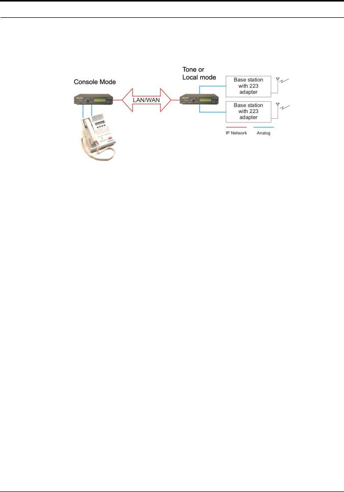
Console Mode – Allows the use of existing tone-based consoles. The IP-223 decodes industry standard tones, converts it to Ethernet traffic to another IP-223 that can be in tone or local mode.
|
|
|
|
|
FIGURE 77. Console Mode Connection |
|
|
Phone Mode – |
Using a PIB (Phone Interface Box) or TDI (Telephone Dispatch Interface), a line on the IP- |
||
|
223 is used to connect to an analog phone line. |
||
iDen Radio Mode – Using the NI-223, allows interface with a Falcon Class PTT (Push-To-Talk) mobile phone system.
TETRA Radio Mode – Used to interface to a TETRA digital trunked system using the IP-223 and the Sepura SRM2000 mobile radio. The IP-223 interfaces the radio through the PEI (Peripheral Equipment Interface) allowing dispatch access to TETRA radio assets.
Features
NOTE: The features listed below for the IP-223 version 4.100 do not comprise the full feature set. For more information on all the features available, contact Radio Dispatch Sales listed on www.telex.com
.
•Ethernet TX and LINK LEDs
•PTT, Monitor, F1 and F2 relays (programmable to any function tone or revert to F1)
•Four (4) PTT modes and three (3) monitor modes
•Nine (9) selectable PTT frequencies
•Seven (7) digital outputs for channel selection, completely programmable per function tone
•CTCSS (Continuous Tone Coded Squelch System) generation (64 frequencies)
•Hardware and software gain control
•Local handset port for monitoring activity and transmission back to base or to radio
•RS-232C port on rear for initial configuration and direct radio control
•Single function tone recognition (16 function tones)
•RX (Receive) audio squelch
•Crosspatch capability
•ANI (Automatic Number Identification) over-the-air- protocol—decode and display
•Provides iDEN interface
•Supports Sepura SRM2000, TETRA radio
•E.F. Johnson RS5300 P25 radio interface
•Remote Crosspatch capabilities
•POTS line fail-over
•Phone line interface
•MDC and Fleetsync Decode
•5/6 Tone signalling encode/decode
•Kenwood radios interface
14

Operating Modes
NOTE: Transient protection is provided near all audio inputs and outputs. The IP-223 line transformers are not designed to operate on lines carrying DC (direct current). If a voltage is on the line, isolate with external capacitors. If the line termination must conduct direct current, install a 600:600 Ohm transformer designed for the current involved.
IP-223 Accessories
There are several optional accessories available for the IP-223:
Part Number |
Description |
|
|
223RACK |
1 unit high rack shelf to hold up to two (2) IP-223 units |
|
|
2490248 |
Alignment Handset |
|
|
730153 |
Power Supply |
|
|
301611000 |
Fleetsync Over the Air Decode |
|
|
301611004 |
FleetSync Encode/Decode |
|
|
301611001 |
MDC Over the Air Decode |
|
|
301912000 |
NI-223 |
|
|
PRD000003000 |
IP223 to EFJohnson 5300 Mobile Radio Advanced Control Interface Box |
|
|
301953000 |
IP223DB9Splitter - Serial Port splitter cable DB9 |
|
|
301956000 |
IP223CAB150/180 - IP223-Kenwood TK-150/180 cable |
|
|
301957000 |
IP223CAB90 - IP223-Kenwood TK-90 cable |
|
|
301969000 |
IP223CABCDM1250 - IP-223-Motorola CDM and GM cable |
|
|
301961000 |
IP223CAB2000 - IP-223-Sepura SRM2000 cable |
|
|
879794 |
IP223CAB Tone - IP-223-Dual DB25 Tone cable 24ft. |
|
|
15
Overview
IP-223 Specifications
The specifications for the IP-223 are listed in Table 1. The specifications are subject to change without notice.
CAUTION: This device is NOT PoE (Power Over Ethernet) compatible.
TABLE 1. IP-223 Specifications
Operating Temperature Range |
0 to 70°C for full specifications |
|
|
Power Requirements |
+12 to +16Vdc, semi-regulated, ~700mA |
|
|
Ethernet Speed |
10 BaseT or 100 BaseTX |
|
|
Lease Lines |
2W and 4W supported |
|
|
Radio Interface |
±45VDC withstand rating |
|
|
Relay Contact Ratings |
1A at 125Vac |
|
|
Non-Relay Outputs |
Open collector, active low, 200mA maximum, 40V collector to emitter voltage |
|
|
Radio Input Level |
10mVpp to 10Vpp, adjustable |
|
|
Radio Output Level |
10mVpp to 10Vpp for mic level or -40 to +10dBm into 600Ω load, adjustable |
|
|
Radio Output Impedance |
600Ω for balanced mode, 200Ω for single ended mode |
|
|
Frequency Response |
±1.5dB, 300 to 3000Hz |
|
|
Audio Distortion |
2% THD maximum |
|
|
DTMF Detection Bandwidth |
± 25 Hz around center of frequency |
|
|
MON timer |
10ms to 9999ms, adjustable |
|
|
Dimensions |
8 ½” (215.9mm) Wide, 9 3/4” (247.65mm) Deep, by 1 5/8” (41.275mm) High |
|
|
Actual Weight |
3.75lb (1.701kg) |
|
|
Shipping Weight and Dimensions |
5lbs (2.267kg) ~ 12”(304.8mm) x 10”(254mm) x3”(76.2mm) |
|
|
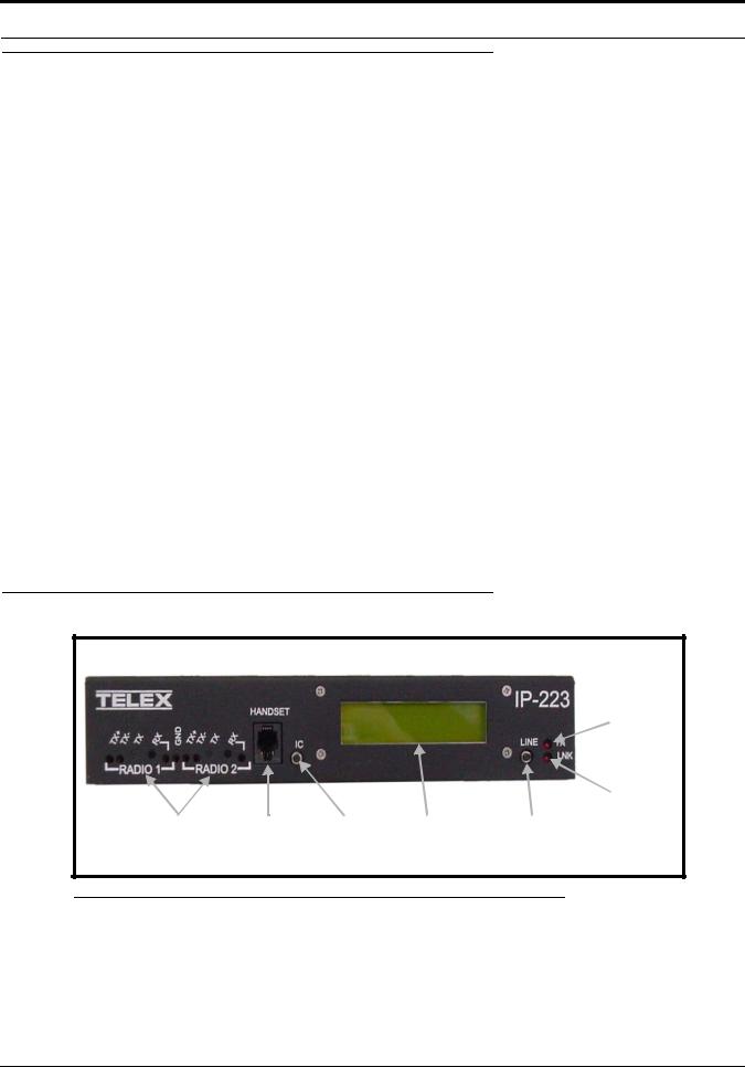
Front Panel
 TX LED
LNK LED
Test and |
Handset IC button LCD display |
Line button |
adjustment points |
jack |
|
FIGURE 78. IP-223 Front Panel
Test and Adjustment Points
Test and adjustment points for Radio 1 and Radio 2 are provided on the front panel. Newer versions of the IP-223 provide access to additional test and adjustment points on the case top, as shown in Figure 79.
16

Front Panel
NOTE: Radio 1 and radio 2 are also referred to as line 1 and line 2 in this manual.
FIGURE 79. IP-223 Case Top Test Points
Handset Jack
An optional handset is available for the IP-223. When the optional handset is plugged into the handset jack, the ability to monitor and talk on either line is available. The handset jack is located on the front of the unit, see Figure 78. When the handset PTT switch is pressed, the selected radio connected to the IP-223 is keyed up on the existing frequency and the handset microphone audio is transmitted.
Ethernet audio is also generated on the TX multicast and port for the selected line. This functionality can be used to test both the Ethernet network and the analog connection.
IC Button
The IC button, when pressed, sends audio from the handset microphone back through the IP Network on the selected TX multicast and port. It also sends audio to the transmit lines of the IP-223 without keying up the radio. This means no PTT relay in local mode and no EIA (Electronic Industries Association) tones in tone mode.
NOTE: A handset is required to use the IC button.
LCD Display
The LCD display provides panel status information, such as the IP and subnet addresses, line status, and handset line selection.
•TX F# (# is the selected function tone) indicates a PTT is active.
•RX F# (# is the selected function tone) indicates the RX radio is active.
•ID # displays when a Fleetsync or MDC ANI ID is decoded. This does not include serial decoding.
17

Overview
•When connected to a serially controlled radio, iDEN, Sepura, Kenwood or Johnson displays.
•INTCOM displays when the front panel IC button is pressed.
•EnetIC displays when the console generated intercom is received.
•CTX F# displays when the console mode IP-223 decodes tones from a tone console in Console mode.
•CRX F# displays when the IP-223 transmits wire-line audio to a legacy tone console in Console mode.
•PTX F# displays when the IP-223 decodes tones from a legacy tone console attached in parallel in Tone mode.
•CPT F# displays when the IP-223 transmits to a line if the line-to-line crosspatch is enabled.
•Ring displays when there is an incoming phone call in Phone mode.
•Offhook displays when the line is in use during a phone call.
•LLM displays when no phone line is connected to the PIB or TDI in Phone mode.
•NO LINE ENABLED displays after power-up if neither line is enabled.
•Scan List.... displays during power up while the IP-223 is communicating with serial controlled radios that support the Scan List feature.
To toggle the LCD display, do the following:
1.Press and hold the line button and then momentarily press the IC button.
Three different displays are available with each press of the IC button:
•While pressing the line button, press the IC button once.
The IP Address and Mask Address of the unit displays.
•Continue to hold the line button, then press the IC button a second time.
The TX alignment tones are turned ON.
•Continue to hold the line button, then press the IC button a third time.
The RX VU meter displays.
2.Press the IC button a fourth time to clear the display and return to the normal LCD display.
3.Release the line button.
Line Button
The Line button is used to select which radio, or line, the handset audio is routed and which line is being monitored. The handset line selection is displayed as an asterisk (*) in the right most column of the LCD display. An asterisk (*) on the top line of the display indicates a connection to line 1, and an asterisk (*) on the bottom line of the display indicates a connection to line 2.
TX LED
The TX LED provides a visual indication the IP-223 is generating IP packets. When the LED is illuminated, packets are being transmitted to the network.
LNK LED
The LNK LED provides a visual indication of the Ethernet connection. When the LED is illuminated, a valid network connection is established.
18
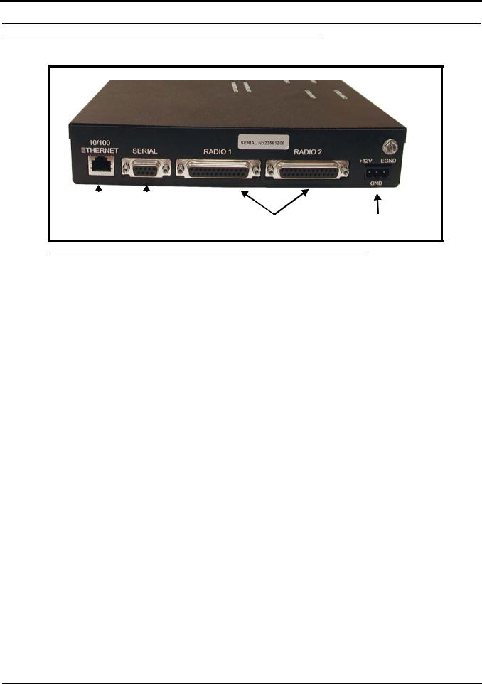
Back Panel
Back Panel
|
|
|
|
|
|
|
|
Serial |
|
|
|||||
10/100 |
Radio 1 and radio 2 |
Power |
|||||
Ethernet |
connector |
||||||
connector |
(DB9) |
connectors (DB25) |
connection |
||||
FIGURE 80. IP-223 Back Panel
10/100 Ethernet Connector
The 10/100 Ethernet connector provides the LAN or WAN connection for the IP-223.
Serial Connector
The serial connector (DB9) is used for either of the following:
•To program an initial IP Address into the IP-223 unit, if the IP Address cannot be programmed through the Ethernet port on the installed system.
NOTE: To communicate with HyperTerminal, the jumper setting must be RS-232.
•To provide serial communication to various radios. Both radio (or line) 1 and radio (or line) 2 are supported on this connector, with the appropriate splitter cable.
NOTE: You must adjust the position of the jumper, on J35 when using line 1, or on J26 when using line 2, according to the serial connection type for the radio interface shown below. See “Jumper Positions” on page 25 for more information.
Jumper position |
Connection type |
|
|
A |
RS-232 |
|
|
B |
TTL |
|
|
TABLE 2. Jumper Position
19

Overview
SERIAL DB9 PINOUT
SIGNAL |
LINE # |
DB9 PIN # |
|
|
|
TX 232 |
1 |
2 |
|
|
|
RX 232 |
1 |
3 |
|
|
|
TX TTL |
1 |
9 |
|
|
|
RX TTL |
1 |
1 |
|
|
|
Ground |
both |
5 |
|
|
|
TX 232 |
2 |
8 |
|
|
|
RX 232 |
2 |
7 |
|
|
|
TX TTL |
2 |
4 |
|
|
|
RX TTL |
2 |
6 |
|
|
|
TABLE 3. DB9 Pinout |
|
|
Radio 1 and Radio 2 (Line 1 and Line 2) Connectors
Two (2) DB25 connectors are provided for connection to various audio devices. The pinouts shown in Table 4 are used when custom cables need to be fabricated.
Power Connection
The IP-223 requires +12 to +16VDC, ~700mA of clean power. A 3-pin screw terminal receptacle is provided on the right rear of the unit, pin 1 is the positive terminal, pin 2 is the ground terminal, and pin 3 is the earth ground terminal.
As with all communication equipment earth ground should be used. Earth ground is a low impedance path to earth for the purpose of discharging lightening, static, and radiated energy.
20

Back Panel
FIGURE 81. DB25 Connector Pinout Configuration
TABLE 4. DB25 Connector Pinout Connections
Pin # |
Signal |
Cable color |
|
|
|
1 |
PTT Relay N.C. |
Brown |
|
|
|
2 |
PTT Relay Common |
Red |
|
|
|
3 |
MON Relay N.O. |
Orange |
|
|
|
4 |
R1 Relay N.C. |
Pink |
|
|
|
5 |
R1 Relay Common |
Yellow |
|
|
|
6 |
R2 Relay N.O. |
Green |
|
|
|
7 |
Ground |
Lt. Green |
|
|
|
8 |
Digital 0/X-Mute |
Blue |
|
|
|
9 |
Digital 2 |
Violet |
|
|
|
10 |
Digital 4 |
Gray |
|
|
|
11 |
CTCSS |
White |
|
|
|
12 |
Radio RXin / 4-wire RX |
Black |
|
|
|
13 |
Radio TXout / 4-wire TX or 2-wire |
Brown/White |
|
|
|
14 |
PTT Relay N.O. |
Red/White |
|
|
|
15 |
MON Relay N.C. |
Red/Black |
|
|
|
16 |
MON Relay Common |
Orange/White |
|
|
|
17 |
R1 Relay N.O. |
Orange/Black |
|
|
|
18 |
R2 Relay N.C. |
Pink/Black |
|
|
|
19 |
R2 Relay Common |
Yellow/Black |
|
|
|
20 |
Digital 6/COR |
Green/White |
|
|
|
21 |
Digital 1/Supervisory |
Green/Black |
|
|
|
22 |
Digital 3 |
Blue/White |
|
|
|
23 |
Digital 5/Local PTT |
Violet/White |
|
|
|
24 |
Radio RX+ input / 4-wire RX |
Gray/Black |
|
|
|
25 |
Radio TX+ out / 4-wire TX or 2-wire |
Black/White |
|
|
|
Shield |
Ground |
|
|
|
|
21

Overview
22
CHAPTER 2
Communications System Design
Designing an IP-223 system requires an understanding of the radio network and how the various radios and communication equipment are connected.
The first step in designing an IP-223 system is to create a roadmap of the radio, console, and any other communication equipment locations. This roadmap must include the following:
•Multicast addresses for each channel of TX (transmit) and RX (receive) communication.
•Port numbers for each channel of TX and RX communication.
•Base IP Addresses assigned to each console and IP-223 on the network.
Network Requirements
Bandwidth
Each VoIP channel requires 50kBit of bandwidth while active. Full-duplex conversation (audio in each direction) requires 100kBit of bandwidth.
NOTE: Most radio voice communications are half-duplex (only in one direction at any one time), thus requiring 50kbits.
Some radio systems transmit go-ahead beeps when it is clear to talk. In order for the console operator to hear the beeps, the system must support full-duplex communication. Full-duplex bandwidth may only be required for the first few seconds of a conversation, due to the brief nature of the go-ahead beeps at the beginning of the transmission.
When using a PIB, TDI, C-6200, or the NI-223 for a telephone connection, 100kBit is required since it is a constant, fullduplex conversation.
Multicast
In general, Telex systems require multicast to function. The network must be able to support the multicast traffic generated by the system.
It is very common for networks to enable multicast after an IGMP (Internet Group Management Protocol) join message is sent out, and then prune off branches after a period of time. Due to the intermittent usage patterns of two-way radios, such a system can appear to work flawlessly for a period of time, then no longer work.
23

Communications System Design
NOTE: When using Cisco technology, IP PIM dense mode is generally recommended. Generally speaking, sparse- dense-mode can also be implemented effectively. We recommend explicitly joining the multicast group with an IP IGMP static-join X.X.X.X command. For more information on Cisco and IGMP, visit www.cisco.com
Internet Group Management Protocol (IGMP)
IGMP can be used to control where multicast is allowed to propagate. When a console on the subnet is expected to be continually operational, multicast must be active for that subnet at all times.
Network Performance
Networks should perform well under any loading conditions. The default audio delay is 120ms, plus any delay added by the network. While delay alone does not cause issues, variable delay (jitter) does. Jitter in a network cannot exceed the maximum packet buffer of any individual product buffer. Refer to the individual product manuals for these specifications. For example, the IP-223 can handle approximately 600ms of network jitter.
NOTE: Losing more than 5% of the total packets transmitted compromises audio quality and system performance. Optimally, packet loss should be less than 1%.
24

CHAPTER 3
Installation and Level Settings
Local/Radio Connections
NOTE: Connections to radios differ from connections for remote operation; therefore connections are discussed separately.
Jumper Positions
An example of the jumper positions are shown in Figure 82. In the figure, jumper 14 (J14) is shown in position A, jumper 3 (J3) is shown in position B, and jumper 23 (J23) has been placed on the center pin indicating the jumper is in the NULL position.
FIGURE 82. Jumper Positions
To adjust the position of a jumper, do the following:
1.Remove power from the IP-223 unit.
CAUTION: Failure to remove power may cause damage to the IP-223.
2.Remove the six (6) screws from the case top.
25
Installation and Level Settings
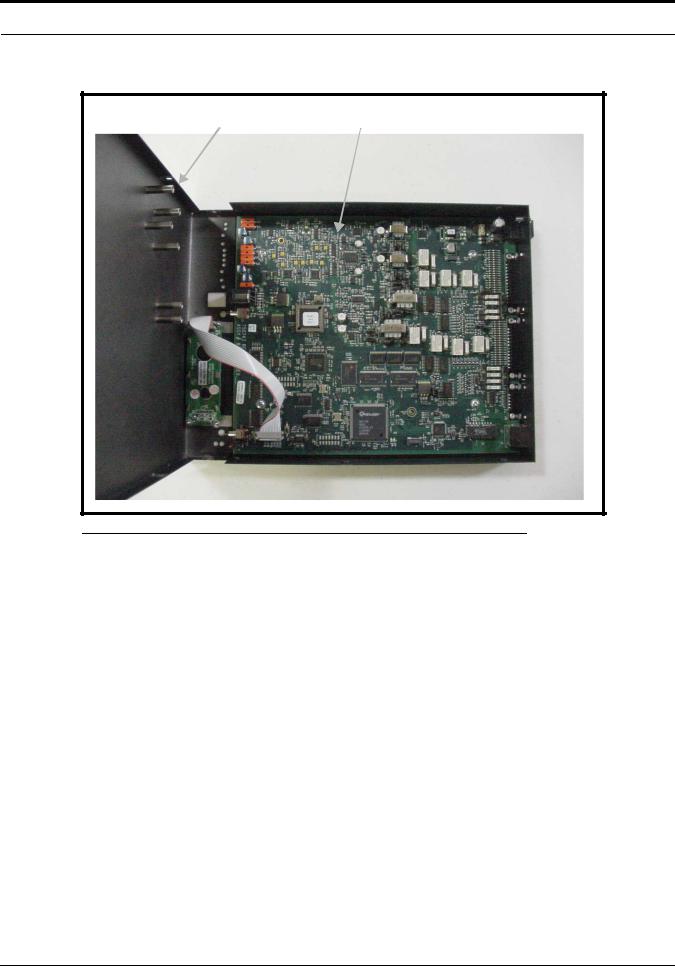
3.Carefully slide the case top forward past the IC and LINE buttons, and then lift up to gain access to the PCB (Printed Circuit Board) as shown in Figure 83.
Case top |
PCB assembly |
FIGURE 83. IP-223 PCB Assembly
4.Locate the desired jumper on the PCB assembly and use needle nose pliers to adjust the jumper, if necessary.
5.Carefully lift up the case top and place it into position on the chassis bottom.
6.Secure the case top into position using the six (6) screws.
7.Connect power to the IP-223 unit.
26

Local/Radio Connections
TX Audio Connection
The IP-223 has a number of options when connecting to the radio. Different jumper settings are required for different revisions of the PCB installed in the IP-223 unit, and are noted below. Set the jumper position listed for the line according to the connection type shown below.
If the radio transmit audio output is balanced,
•connect to pins 13 and 25 of the DB25 connector.
If the transmit audio is single ended,
•use pin 25 of the DB25 connector.
NOTE: Shielded cable is recommended.
PCB 750743 or PCB 750630 revision C and higher
Line 1 jumpers: J3, J9, and J11
Line 2 jumpers: J25, J28, and J29
Jumper Position |
Connection Type |
|
|
A |
Single Ended Low-Impedence |
|
|
B |
Balanced 600 ohm |
|
|
RX Audio Connection
To connect the radio receiver audio to the IP-223, different jumper settings are required for different revisions of the PCB installed in the IP-223 unit, and are noted below. Set the jumper position for the line according to the connection type shown below.
•If the radio receiver audio output is balanced, connect to pins 12 and 24 of the DB25 connector.
•If the receiver audio is single ended, use pin 24 of the DB25 connector. The audio source must be after the squelch circuit to prevent sending continuous noise to the remote console.
•If a high-impedance point in the receiver is used, a shielded cable is recommended.
PCB 750743 or PCB 750630 revision C and higher
Line 1 jumpers: J16 and J21
Line 2 jumpers: J19 and J20
Jumper Position |
Connection Type |
|
|
A |
Single Ended Low-Impedence |
|
|
B |
Balanced 600 ohm |
|
|
27

Installation and Level Settings
|
Jumper Position |
|
|
|
|
|
Line 1 |
Line 2 |
|
|
|
Receive Input Impedance: |
J14 |
J24 |
|
|
|
8 ohms (for a speaker input) |
B |
B |
|
|
|
600 ohm |
A |
A |
|
|
|
10k ohm |
NULL |
NULL |
|
|
|
NOTE: When the speaker output is used, the radio volume control affects the audio levels of the IP-223.
|
|
|
Jumper Position |
|
|
|
|
|
|
|
|
|
|
|
Line 1 |
|
|
Line 2 |
||
|
|
|
|
|
|
|
Receive Input Impedance: |
J14 |
|
J23 |
J17 |
|
J24 |
|
|
|
|
|
|
|
8 ohms (for a speaker input) |
B |
|
A |
A |
|
B |
|
|
|
|
|
|
|
600 ohm |
A |
|
B |
B |
|
A |
|
|
|
|
|
|
|
10k ohm |
B |
|
B |
B |
|
B |
|
|
|
|
|
|
|
COR (Carrier Operated Relay) I/O (Input/Output)
The COR I/O connection indicates that audio is being received from the radio. The COR connection is provided at DIG6, pin 20 of the DB25 connector.
PTT Connection
Connect the radio PTT circuit to the PTT relay contact terminals on the DB25 connector. Usually the common of the relay contact switch is grounded and the normally open contact connects to the PTT input. An alternative method to ground the common of the relay internal to the unit is to jumper R377 (line 1) and R381 (line 2) with a piece of wire soldered closed.
Monitor Connection
Connect the radio MON circuit to the MON relay contact terminals on the DB25 connector. Usually the common of each relay contact switch is grounded and the normally open contact connects to the MON input. An alternative method to ground the common of the relay internal to the unit is to jumper R376 (line 1) and R380 (line 2) with a piece of wire soldered closed.
R1 and R2 Relays
The IP-223 provides two (2) relay closures for controlling the frequency of the radio, or switching a remote ancillary device. The F1 and F2 contacts can be connected through the DB25 connector. Usually the common of each relay contact switch is grounded and the normally open contact connects to the radio frequency control terminals. Information on programming the R1 and R2 relays is provided in the “Setup Information” chapter of this manual starting on page 33. An alternative method to ground the common of the relay R1 internal to the unit is to jumper R375 (line 1) and R379 (line 2), and for relay R2 jumper R374 (line 1) and R378 (line 2) with a piece of wire soldered closed.
28

Tone/Console Operation
Digital I/O
In addition to the two standard relay closures, seven (7) lines of digital I/O are also included. These lines are open-collector transistor outputs. They can be programmed on a per line basis to generate any of 128 combinations. They pull down to ground and can be jumper selected to pull up to either +5V or the power supply voltage (minimum +12V).
Jumpers J8 (line 1) and J30 (line 2) are used to select the pull up voltage. Jumper position A pulls up to +5V and jumper position B pulls to the power supply value.
NOTE: Some radios provide a pull-up voltage. When this occurs, place the jumper into the null position. Information on programming the digital I/O lines is provided in the “Setup Information” chapter of this manual starting on page 33.
CTCSS (Continuous Tone Coded Squelch System) Connection
The IP-223 connection can be used for a recorder output or as a CTCSS output:
Recorder output - The analog audio is generated at the connection.
CTCSS output - Each function tone can be assigned a CTCSS number which corresponds to a CTCSS frequency. See “CTCSS Tone Frequency Table” on page 131.
Tone/Console Operation
Tone and Console operation require jumpers set to specific locations. The following section discusses the jumper settings. See “Jumper Locations” on page 125.
2-/4-Wire Jumper Settings
2-Wire / 4-Wire Selection: |
Line 1 |
Line 2 |
|
|
|
2-Wire A position |
J33 and J34 |
J5 and J6 |
|
|
|
4-Wire B position |
J33 and J34 |
J5 and J6 |
|
|
|
The RX termination J14 (line 1) and J24 (line 2) should be placed in jumper position A on 4-wire systems for a single unit at the end of a line. If multiple units are connected in parallel, only one (1) unit should have the RX termination jumper in the A position. The RX termination jumper should be in the null position on the rest of the units.
For 2-wire operation:
•PCB 750743 or PCB 750630 revision C and higher - Set J14 or J24 to the NULL position.
TX Side Settings
PCB 750743 or PCB 750630 revision C and higher
Two (2) jumpers on the transmit pair allow a degree of control over the output impedance. The jumper positions for each line, depending on how many consoles are placed in parallel, are shown below.
NOTE: PCB 750630 revision A does not have these jumpers.
29

Installation and Level Settings
Jumper Position
|
|
Line 1 |
|
Line 2 |
|
||
|
|
|
|
|
|
|
|
Consoles in Parallel: |
J17 |
|
J22 |
J10 |
|
J15 |
Output Impedance |
|
|
|
|
|
|
|
|
1 |
B |
|
B |
B |
|
B |
600 ohms |
|
|
|
|
|
|
|
|
2 |
A |
|
B |
A |
|
B |
1200 ohms |
|
|
|
|
|
|
|
|
3 |
B |
|
A |
B |
|
A |
1800 ohms |
|
|
|
|
|
|
|
|
4 |
A |
|
A |
A |
|
A |
2400 ohms |
|
|
|
|
|
|
|
|
Local PTT I/O
The Local PTT I/O is used to generate TX Ethernet traffic on a local keyed system as opposed to the 2175Hz detection on a tone keyed system. The input is at DIG5; pin 23 of the DB25 connector. The TX condition is caused by an active low.
Cross Mute I/O
Cross mute information to local consoles is provided at DIG0, pin 8 of the DB25 connector.
Supervisory I/O
Supervisory information to and from consoles is provided at DIG1, pin 21 of the DB25 connector. The supervisory I/O is both an input and an output.
Supervisory input and output in console, tone or local mode behaves as follows:
Console Mode – Input - An Ethernet packet supervisor is sent on detection.
Output - When an Ethernet packet is received. The line level is set.
While under supervisory control, TX traffic from the Ethernet to the console is muted. The console’s audio to the Ethernet is muted. Handset PTT and the IC button are disabled.
Tone Mode – Input - An Ethernet packet supervisor is sent on detection.
Output - When an Ethernet packet is received, the line level is set.
When an Ethernet packet is received, the line level is set.
Local Mode - InputNo affect on I/O.
Output - No affect, when Ethernet packet is received.
While under control, manual PTT and the IC button are disabled.
NOTE: Information on programming the supervisory I/O is provided in the “Setup Information” chapter of this manual starting on page 33..
Level Adjustments
Once the IP-223 unit is connected to the system, the level potentiometers can be set. Access to test and adjustment points on newer versions of the IP-223 are provided through labeled openings on the case top and on the front panel of the unit. On older versions of the IP-223, access to some of the test and adjustment points is provided through labeled openings on the front panel; however, the case top needs to be opened to access the other test and adjustment points.
30

Level Adjustments
General Alignment
The IP-223 has a TX alignment tone and an RX alignment VU meter accessible from the front panel of the unit.
•Press and hold the line button and then momentarily press the IC button twice to generate the 1kHz 0dB TX alignment tone on both lines.
•Press and hold the line button and then momentarily press the IC button three times to display the RX VU meters.
Radio/Line TX Level
The Radio 1 TX test points (TP2 and TP6) and the Radio 2 TX test points (TP8 and TP9) are located on the front panel of the IP-223. These provide a point to measure the actual signal being placed into the radio or balanced TX line. The front panel accessible adjustment Radio 1 TX potentiometer (R47) and Radio 2 RX potentiometer (R61) are used to adjust these levels.
NOTE: If the unit is placed into single-ended mode, the radio TX+ should be measured with respect to ground.
It is also possible to place jumper J9 (line 1) or J26 (line 2) into the A position to decrease the output of the TX line by a factor of 10. The final adjustment should allow for undistorted audio to be transmitted for the full range of transmission levels at the desired deviation. This can be accomplished by turning on the TX alignment tone and adjusting the TX output to 0dB, as measured into a 600 ohm load.
Radio/Line RX Level
Standard Alignment Procedure for a 2- or 4- wire System:
•Inject a 0dBm test tone on the RX pair (4-wire pins 12 and 24: 2-wire pins 13 and 25).
•Measure the RX level on test point TP13 for line 1 or TP1 for line 2.
•Adjust potentiometer R175 for line 1 or potentiometer R110 for line 2 until 0dBm is measured between the test point and GND. (0dBM = 2VPP = .707VRMS)
•Detune slightly 1-2dBm to provide overhead for large transients.
•AGC (Automatic Gain Control) compression potentiometers RV5 for line 1 and RV1 for line 2 control the aggressiveness of the AGC circuitry, if enabled. The AGC can be used to enhance the gain capabilities of the RX circuitry. Set RV5/RV1 fully clockwise and, if required, back off 10 to15 degrees maximum.
•Use the RX alignment tool (VU meter) accessed through the LCD display (press and hold the line button and then momentarily press the IC button 3 times) to verify the dBm level. The reading should be 0dBm with the AGC turned off. If the AGC is ON, it is likely the RX alignment software always displays 0dBm, the targeted level for the AGC circuitry.
Line TX Monitor Level (Tone and Console Mode only)
PCB 750743 or PCB 750630 revision C and higher
The Line TX Monitor Level adjustment is used when the IP-223 is connected to consoles set in 4-wire mode. This allows for local TX audio to be sent back on the Ethernet and played at other consoles so both sides of the radio traffic can be heard. The alignment for TX monitor is similar to 4-wire RX alignment.
31

Installation and Level Settings
To adjust the TX monitor, do the following:
1.In the options section of the Per Line Setup window, select the TX Monitor.
NOTE: If this feature is not necessary, or the line is in 2-wire mode, the TX Monitor field in the Options section on the Per Line Setup window should be cleared.
2.Verify the RX alignment is completed first.
To perform a standard alignment for a 4-wire system, do the following:
1.Transmit a 0dBm test tone on the TX audio pairs pins 13 and 25.
2.Measure the RX level on test point TP13 for line 1 or TP1 for line 2.
3.Adjust potentiometer R390 for line 1 or potentiometer R391 for line 2 until 0dBm is measured between the test point and GND. (0dBM = 2VPP = .707VRMS).
NOTE: Do not adjust the RX potentiometers.
4.Use the RX alignment tool (VU meter) accessed through the LCD display (press and hold the line button and then momentarily press the IC button 3 times) to verify the dBm level.
CTCSS Level
The CTCSS level is measured by connecting an oscilloscope or RMS meter to ground and Radio 1 CTCSS test point (TP7) or Radio 2 CTCSS test point (TP10). With the radio connected to the CTCSS output, have the remote console open to receive audio so CTCSS is present. Adjust the Radio 1 CTCSS potentiometer (R50) or Radio 2 CTCSS potentiometer (R53) until the desired level is achieved.
Frequency Decoding
The IP-223 is factory tuned to the frequencies shown below. The detection frequencies cannot be changed as they are coded into the software. However, any actual function or output can be made to work with any existing programmed frequency. Please consult the factory for special requirements for frequency selections.
Guard tone/PTT Tone: 2175 Hz |
|
|
|
MON Function Tone: 2050 Hz |
|
|
|
Frequency Select Function Tones (where used) |
|
||
F1: 1950 Hz |
F5: 1550 Hz |
F9: 1150 Hz |
F13: 750 Hz |
F2: 1850 Hz |
F6: 1450 Hz |
F10: 1050 Hz |
F14: 650 Hz |
F3: 1750 Hz |
F7: 1350 Hz |
F11: 950 Hz |
F15: 550 Hz |
F4: 1650 Hz |
F8: 1250 Hz |
F12: 850 Hz |
F16: 450 Hz |
32
Loading...