


TelexR
Operating Instructions
FMR-500
User Guide

Section 1 - Quick Set-Up
Quick Set-up: Receiver
1.Do not connect the receiver to any other equipment yet!
2.Connect the two antennas to the receiver.
3.Plug the power supply into the back of the receiver and into an outlet.
4.Press the POWER switch. Display will light up.
5.P r es s a n d h o l d th e S ET b u t t o n u n t i l ClearScanTM shows and starts flashing on the
right side of the screen.
6.When ClearScan stops flashing, the receiver will automatically set itself and display the clearest group and channel.
7.If you are using a guitar, turn off the receiver. Press and hold SET while you turn the receiver on. A guitar symbol will appear in the display to indicate instrument mode.
8.Turn the receiver off and connect the mixer or other audio system to the receiver XLR Connector or the ¼ inch Line Level Jack.
9.Set the audio mixer or other system input level to minimum.
10.Press the Power switch button in again.
Receiver “Quick Set-up” is complete.
Quick set-up: Transmitter
1.With the Power Switch on the transmitter OFF, install a fresh alkaline battery into the transmitter.
2.Place the transmitter Power Switch to the ON position.
3.The Red Battery Low Light near the display will flash on and then off. The display will also come on and display a group and channel.
4.Press the SET button once and the Group number will flash.
Section 2 - System Description
5.Use the up and down arrows to change the Group number to match the Group number displayed on the receiver. Press SET and the Channel Number will flash.
6.Use the up and down arrow buttons to change the Channel to match the receiver. Press Set and nothing will be flashing. The channel is now set.
7.If you are using a bodypack transmitter, plug the microphone into the transmitter connector. If using a guitar, turn the transmitter off and wait until display is blank. Hold SET down and turn the transmitter on. A guitar symbol should appear on the display. Plug the cord into the transmitter and guitar.
Transmitter “Quick Set-up” is complete.
Quick set-up: System Operation
1.With the transmitter and receiver on, monitor the display screen. Note that the RF (1-100) Bar graph should indicate near the 100 mark. The AF Bar should show very little, if any, indication until you talk or sing into the microphone. While talking or singing in the loudest voice used in performance, adjust the transmitter gain control if necessary to cause the AF Bar Graph to peak near -6 to -3 but not over +3 for best performance.
2.Set the mixer/amp gain.
3.Talk or sing into the microphone or play the guitar at a normal volume. You should hear audio coming out of the system.
4.If using the unbalanced 1/4" output, you may have to adjust the gain (via the control next to the connector on the back panel) to match the level found when singing or playing with a wired connection.
"Quick Set-up" is now complete.
Please enjoy your FMR-500 system.
The FMR-500 Wireless Microphone system combines frequency agility and ease of use like no other. The transmitters and receivers operate over a 24 MHz bandwidth in the UHF portion of the Radio Frequency spectrum.
System Features Include:
The high quality audio circuitry and advanced Radio Frequency (RF) signal processing offer broadcast quality signal-to-noise and audio clarity.
•Advanced ClearScan technology for selecting the clearest available channels in intermodulation free groups
•Completely programmable in 25 kHz steps for over 950 possible frequencies
•LCD Displays for ease of viewing-Group, Channel, Frequency, Battery Status, Diversity Activity, Audio Meter and RF Meter
•Patented Phase Diversity System
•Adjustable Unbalanced Line Level 1/4 inch output jack
•Balanced XLR output jack for fixed Microphone Level or adjustable Line Level
-1-
•Front Panel Power ON/OFF Switch
•Front Panel Software Control of Squelch settings
•Double Squelch (Amplitude and Tone) system prevents false squelch
•Lockout feature to prevent accidental channel changes
•"Smart" battery feature in the transmitter means there is no wrong orientation
•Power Lock On feature prevents accidental turn off
•Battery level displayed at the receiver
Section 3 - Detailed Components Description
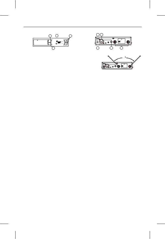
FMR-500 Receiver Controls, Connectors, and Indicators
|
|
|
1 |
2 |
|
|
3 |
|
8 |
5 |
|
|
|
|
|
|
|
|
|
|
|
|
|
|
|
|
|
|||||||
|
|
|
|
|
|
|
|
|
|
|
|
|
|
|
|
Balanced U.S. Patent No. 6,256,484 |
|
|
|
|
|
|
|
|
|
|
||||||||
|
|
|
|
|
|
|
|
|
|
|
|
|
|
|
|
Audio |
|
|
|
|
|
|
|
|
|
Telex |
|
|
|
|
|
|||
|
|
Telex |
|
|
|
|
|
|
|
|
|
|
|
12-15V |
|
|
|
|
|
|
|
|
|
|
Antenna |
|||||||||
|
|
power |
|
|
-20 -10 -6 |
- 3 |
0 +3 |
|
|
|
|
AC/DC |
|
|
|
|
|
|
|
|
|
|
FMR-500 BAND A |
|
|
|
|
|
||||||
|
|
GPA CH |
|
|
+ |
|
- |
|
|
|
|
|
|
|
|
|
|
|
|
|
Tested to Comply |
|
|
|
|
|
||||||||
|
|
CLEAR |
|
|
|
|
|
|
|
|
|
|
|
|
|
|
|
|
|
|
|
|
|
|
|
|
|
|
with FCC Standards |
|
|
|
|
|
|
|
SCAN |
|
12u 05 |
|
|
|
|
|
|
|
|
|
|
|
|
|
|
|
|
|
|
|
|
|
|
|
|
|
|
|
|
|
|
|
|
FMR-500 |
|
E V |
|
|
|
|
|
|
|
|
|
|
|
|
|
|
|
|
|
High |
|
|
|
|
CANADA |
|
|
|
|
|
||
|
|
|
|
|
|
|
|
|
|
|
|
|
|
Mic Line |
Line |
|
|
|
|
S.N. 1059 |
|
|
|
|
|
|||||||||
|
|
|
set |
AU DIO |
1 3 10 |
30 |
100 |
|
|
|
|
|
|
|
|
|
|
|
|
Z |
|
|
|
|
|
|
|
|
|
|
||||
|
|
|
|
|
|
|
|
|
|
|
|
|
|
|
|
Level |
|
|
|
|
Telex Communications, Inc. |
Made in U.S.A. |
||||||||||||
|
|
|
|
|
|
|
|
|
|
|
|
|
|
|
|
|
|
|
|
|
|
|
|
|
|
|
|
|
|
|
|
|
|
|
|
|
|
|
3 |
|
|
|
|
|
|
|
|
|
|
|
|
|
|
|
|
|
|
|
|
|
|
|
|
|
|
|
|
|
|
|
|
|
|
|
|
|
|
|
|
4 |
|
|
|
|
|
|
|
|
6 |
|
|
|
|
7 |
|
|
|
|
|
|||||
|
Figure 1 - FMR-500 Front Panel |
|
Figure 2 - FMR-500 Back Panel |
|||||||||||||||||||||||||||||||
1. Power ON/OFF |
|
3. Display Control Buttons (Set/Up/Down) |
|
|
|
|
|
|
|
|
|
|
|
|
|
|
90 |
|
|
|
|
|
||||||||||||
2. Graphical Display |
|
4. Power Connector |
|
|
|
|
|
|
|
Balanced U.S. Patent No. 6,256,48 |
|
|
|
|
|
|
||||||||||||||||||
a. |
Channel Display |
|
5. XLR BalancedMic/Line Level |
|
|
|
|
|
|
Audio |
|
|
|
|
|
|
Telex |
|
|
|
|
|
||||||||||||
|
|
|
|
|
|
12-15V |
|
|
|
|
|
|
|
|
|
|
Antenna |
|||||||||||||||||
|
|
|
|
|
|
AC/DC |
|
|
|
|
|
|
|
|
|
FMR-500 BAND A |
|
|
|
|
||||||||||||||
b. |
Frequency |
|
|
Audio Output Line Level Adjustable |
|
+ - |
|
|
|
|
|
|
|
|
High |
|
|
|
|
|
|
|||||||||||||
|
|
|
|
|
|
|
|
Mic |
|
Line |
Line |
|
|
|
|
|
|
|||||||||||||||||
|
|
|
|
|
|
|
|
|
|
|
|
Level |
Z |
Telex Communications, Inc. Made in U.S.A. |
||||||||||||||||||||
c. |
Battery Strength |
|
6. Unbalanced Line Level Audio Output |
|
Proper Antenna Orientation |
|||||||||||||||||||||||||||||
d. |
Indicator |
|
|
Connector with Level Adjustment |
|
|
|
|
||||||||||||||||||||||||||
Diversity Indicator |
7. TNC Antenna Input Connectors |
|
|
|
|
|
|
|
|
|
|
|
|
|
|
|
|
|
|
|
|
|
|
|
||||||||||
e. |
RF Strength of |
|
|
|
|
|
|
|
|
|
|
|
|
|
|
|
|
|
|
|
|
|
|
|
|
|||||||||
|
|
|
|
|
|
|
|
a. |
ClearScan for Groups: From the main dis- |
|||||||||||||||||||||||||
|
Signal Indicator |
|
8. Power Cord Retainer |
|||||||||||||||||||||||||||||||
f. |
|
|
play screen, push SET once and the Group |
|||||||||||||||||||||||||||||||
Audio Level Indicator |
|
|
|
|
|
|
Number will flash. While Group is flashing, |
|||||||||||||||||||||||||||
g. |
Guitar Mode Indicator |
|
|
|
|
|
|
|||||||||||||||||||||||||||
|
|
|
|
|
|
press and hold SET until ClearScan appears, |
||||||||||||||||||||||||||||
|
|
|
|
|
|
|
|
|
|
|
|
|||||||||||||||||||||||
Receiver Setup and Operation |
|
release the set key. When the scan is com- |
||||||||||||||||||||||||||||||||
|
pleted, the display will show the group with |
|||||||||||||||||||||||||||||||||
1. Place the receiver and antennas where there is a |
|
the most clear channels and the Channel num- |
||||||||||||||||||||||||||||||||
clear line of sight to the area where the transmit- |
|
ber will indicate how many clear channels are |
||||||||||||||||||||||||||||||||
ter will be used. Rotate the antennas to separate |
|
in that group. Use the UP/DOWN keys and to |
||||||||||||||||||||||||||||||||
them by 90 degrees. |
|
|
|
|
|
|
|
|
view other groups and press SET to select a |
|||||||||||||||||||||||||
|
|
|
|
|
|
|
|
|
|
|
|
group. The Group will be set and the Channel |
||||||||||||||||||||||
2. Connect the power supply cord to the receiver. |
|
will start to flash. Select a channel manually |
||||||||||||||||||||||||||||||||
Plug the power supply into an AC outlet. Turn |
|
or use ClearScan for Channels. |
|
|
|
|
|
|||||||||||||||||||||||||||
the receiver on and confirm that it is ON by |
b. |
ClearScan for Channels: To scan for the |
||||||||||||||||||||||||||||||||
checking the main display screen. |
|
clearest channel in a group, press and hold set |
||||||||||||||||||||||||||||||||
Caution: Please make sure the AC power supply |
|
while the Channel is flashing until ClearScan |
||||||||||||||||||||||||||||||||
|
appears, release the SET button. When the |
|||||||||||||||||||||||||||||||||
is the correct voltage for your local requirements |
|
scan is complete, the display will show the |
||||||||||||||||||||||||||||||||
before it is plugged into the wall. |
|
|
|
|
clearest available channel. Use UP/DOWN to |
|||||||||||||||||||||||||||||
|
|
|
|
|
|
|
|
|
|
|
|
scroll through the other available channels |
||||||||||||||||||||||
3. Manual Channel Change. Press the SET but- |
|
rank from clearest to least clear (but still avail- |
||||||||||||||||||||||||||||||||
|
able for use, ClearScan will not display any |
|||||||||||||||||||||||||||||||||
ton and the Group number will start to flash. |
|
|||||||||||||||||||||||||||||||||
The Up and DOWN buttons allow you to scroll |
|
channel that can't be used). Press SET to se- |
||||||||||||||||||||||||||||||||
through the factory set group. When the group |
|
lect the channel. |
|
|
|
|
|
|
|
|
|
|
|
|
||||||||||||||||||||
you desire is displayed, press SET to select that |
c. |
Auto ClearScan: This function will find the |
||||||||||||||||||||||||||||||||
group and the Channel Number will start flash- |
|
clearest group and channel with the press of |
||||||||||||||||||||||||||||||||
ing. Scroll to the desired channel and press SET |
|
just one button. With nothing flashing, press |
||||||||||||||||||||||||||||||||
to select. The numbers will stop flashing and the |
|
and hold the SET button until ClearScan ap- |
||||||||||||||||||||||||||||||||
new group and channel are installed. |
|
pears on the right side of the screen. When the |
||||||||||||||||||||||||||||||||
|
|
|
|
|
|
|
|
|
|
|
|
scan is complete, the receiver will be set to the |
||||||||||||||||||||||
4. Frequency Assignment (Outside of preset |
|
clearest channel in the clearest group. |
||||||||||||||||||||||||||||||||
Groups and Channels), press SET and UP at |
d. |
ClearScan Band: While in the Frequency |
||||||||||||||||||||||||||||||||
the same time and the group and channel will go |
|
Mode, this function will scan the entire band |
||||||||||||||||||||||||||||||||
blank and the Frequency will start flashing. Use |
|
looking for the clearest frequency, regardless |
||||||||||||||||||||||||||||||||
UP/DOWN to scroll in 25 KHz steps to the de- |
|
of groups and channels. In Frequency Mode, |
||||||||||||||||||||||||||||||||
sired frequency. Press SET and the frequency |
|
press Set once and the frequency will flash, |
||||||||||||||||||||||||||||||||
will be selected and stop flashing. Press Set and |
|
press and hold set until ClearScan appears on |
||||||||||||||||||||||||||||||||
UP at the same time to return to group and chan- |
|
the right side of the display. The scan will |
||||||||||||||||||||||||||||||||
nel operation. Hint: holding in the Up or Down |
|
continue until you press Set again so you can |
||||||||||||||||||||||||||||||||
key will increase the speed of the scroll. Just re- |
|
scan a location overnight, 24 hrs, a week, or a |
||||||||||||||||||||||||||||||||
lease and press again for fine control. |
|
few seconds. When you press Set again, the |
||||||||||||||||||||||||||||||||
|
|
|
|
|
|
|
|
|
|
|
|
scan will stop and the clearest frequency will |
||||||||||||||||||||||
5. Advanced ClearScan: This feature automates |
|
be displayed. You |
|
can |
scroll |
through the 8 |
||||||||||||||||||||||||||||
|
clearest frequencies using the Up and Down |
|||||||||||||||||||||||||||||||||
the |
process of |
finding |
a |
|
clear group of |
|
||||||||||||||||||||||||||||
buttons. Press Set to accept the frequency dis-
inter-modulation free channels and the clearest
played.
channels within those groups.
-2-

NOTE: Groups 9 and above are set up to work with the other US frequency band (A and B). If you are using a mix of Band A and Band B, scroll down to these groups and use the clearest group.
6.Change Lock-Out: By pressing and holding the UP and DOWN arrow keys together for 3 seconds, the SET key is disabled.To reactivate the SET key, simply press and hold the UP and DOWN keys again for 3 seconds. This feature can be useful when the receiver is in a location where unauthorized personnel have access to the receiver.
7.For set up, make sure the mixer or amplifier input used for the FMR-500 is muted or turned down to a minimum level.
8.Plug an audio cable (not supplied) into the 3 pin XLR or 1/4 inch output of the FMR-500.
a.NOTE: The XLR connector is the preferred connection since the output is balanced and will be more immune to noise for longer runs of cable although either can be used with good results. If the 1/4 inch connector is used, adjust the output level on the back panel to 12 o'clock (midway in the range) to start and adjust later if necessary.
Now refer ahead to transmitter setup and return to step 9 when that is completed.
9.With the transmitter on, speak into the microphone or play the guitar. Turn up the level on the mixer or amplifier until you are able to hear the desired signal. If no audio is present, repeat setup and refer to the troubleshooting section.
NOTE: If the 1/4 inch output is used, it may be necessary to adjust the receiver output until the volume level from the wireless system approximates the level of an equivalent wired microphone/instrument.
10.Squelch Adjustment - The squelch setting can be used to maximize range or immunity to noise. Press and hold Up for 3 seconds. The current squelch setting will be displayed. Adjust the squelch using the UP/DOWN keys. Maximum squelch (9) maximizes noise immunity but limits the range. Minimum squelch (1) will maximize the range but allow more noise to break through the squelch. Press SET to save the new squelch setting.
Receiver Push-Button Reference Sheet
Display |
Status Button |
Function Activated |
Edit |
Accept |
Nothing Flashing |
Press and hold SET |
Auto ClearScan |
n/a |
n/a |
Nothing Flashing |
SET |
Edit Group -Group will flash |
|
SET |
Group Flashing |
Press and hold SET |
ClearScan Group - list clear groups in order |
|
SET |
Group Flashing |
SET |
Edit Channel - Channel will flash |
|
SET |
Channel Flashing |
Press and hold SET |
ClearScan Channel - list clear channels in order |
|
SET |
Nothing Flashing |
Press and hold Up |
Edit Squelch Setting |
|
SET |
Nothing Flashing |
Press and hold Up & Down |
Edit Lock - Secure will appear |
n/a |
n/a |
Edit Lock On |
Press and hold Up & Down |
Return to Access Mode |
n/a |
n/a |
Power Off |
Press and hold SET |
Toggle between Guitar and Voice mode |
n/a |
n/a |
Nothing Flashing |
Press SET and Up |
Toggle to Frequency Mode - Freq will flash |
|
SET |
Frequency Flashing |
Press and hold SET |
ClearScan Band - Clear Scan will flash |
n/a |
SET |
ClearScan Band Running |
Press SET |
End ClearScan Band after next full scan |
n/a |
n/a |
ClearScan Band Results |
n/a |
Clearest frequencies listed |
|
SET |
Frequency Mode |
Press SET and Up |
Return to Group and Channel Mode |
n/a |
n/a |
Nothing Flashing |
Press and hold Down |
Display Software Revision |
n/a |
n/a |
|
|
|
|
|
-3-
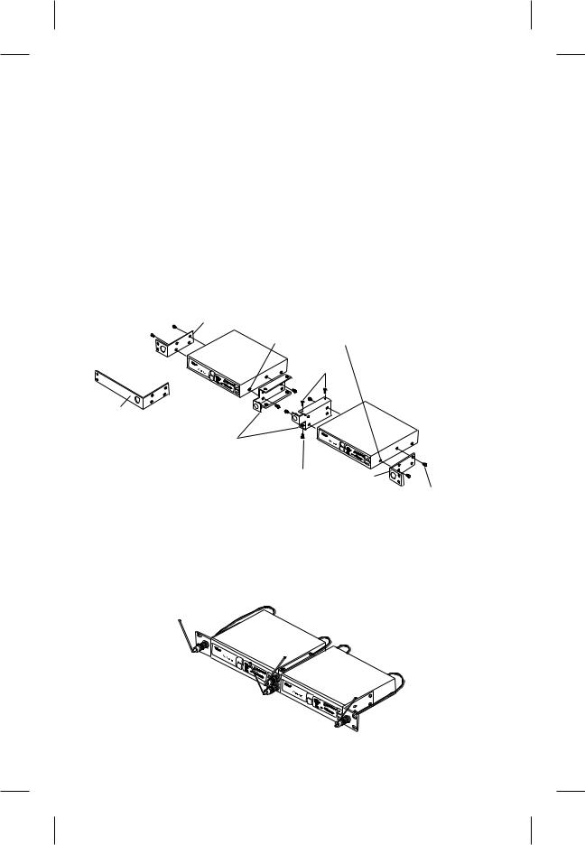
Rack Mount Installation
The FMR-500 is supplied with rack mounts for single and double mounting in a standard EIA 19"/ 483mm equipment rack (see Figure 3). For rack mounting a single unit, a long (#3) and short (#1) "ear" are used. For dual side-by-side mounting, use the short (#1) "ears" and the mid brackets (#2) from two FMR-500's as shown.
To assemble the rack mount adapters to the FMR-500 proceed as follows:
1.Remove the front Phillips head screws from each side of each unit.
2.Align the correct rack ear or bracket with the holes on the side of the unit. Install the previously removed screws. Insert an additional screw (#2, provided in the parts pack) into the remaining hole. Repeat this step for the opposite side of the unit. Be sure to tighten all screws securely.
Four double mounting of two FMR-500's proceed as follows:
1.Align the mid brackets (#2) with the holes on the adjacent sides of each unit.
2.Install the previously removed screws. Insert an additional screw (#4, provided in the parts pack) into the remaining holes. Tighten all screws securely.
3.Place the two assemblies side-by-side with the mid brackets together. (The left bracket should fit above the right so that the countersinks are visible). Install 4 flat head screws (#5, provided in the parts pack) and tighten them securely.
1 |
REMOVE SCREWS |
|
|
|
(TYPICAL 4 SIDES) |
|
5 |
3
2 |
|
(TYPICAL BOTH SIDES) |
|
5 |
1 |
|
4 |
Figure 3 |
(TYPICAL ALL SIDES) |
Rack Mount Installation |
|
Front Mounting Antennas
1.Remove hole plugs from brackets.
2.Attach the antenna connectors to the brackets.
3.Attach the supplied extension cables from the rack connectors to the antenna connections on the back of the receiver. See Figure 4.
CLEA
SCARN
 power
power
set
CLSECAARN
 power
power 
set
Figure 4
Front Mounting Antennas
-4-
 Loading...