

Page 1
conference
LINGUA IR
from
BRAMSHAW
ICS CONFERENCE
COMMUNICATIONS
www.bramshawics.com
t: 1800 507 557
USER & INSTALLATION GUIDE
Page 2

Copyright Statement
No part of this publication or documentation accompanying this product may be reproduced in any form or
by any means or used to make any derivative such as translation, transformation, or adaptation without the
prior written permission of the publisher, except in case of brief quotations embodied in critical articles or
reviews. Contents are subject to change without prior notice.
Copyright © 2019 by Televic Conference NV. All rights reserved.
The authors of this manual have made every effort in the preparation of this book to ensure the accuracy of
the information. However, the information in this manual is supplied without warranty, either express or
implied. Neither the authors, Televic Conference NV, nor its dealers or distributors will be held liable for any
damages caused or alleged to be caused either directly or indirectly by this book.
Trademarks
All terms mentioned in this manual that are known to be trademarks or service marks have been
appropriately capitalized. Televic NV cannot attest to the accuracy of this information. Use of a term in this
book should not be regarded as affecting the validity of any trademark or service mark.
Page 3

CONTENTS
Introduction
Getting started 7
About this manual 7
Compatibility 8
About Lingua IR 9
Concept anddesign 9
Safety Instructions
Safety instructions 12
Safety 12
FCC & ICES Information 12
Conformity and Certification Info for Japan 13
Important safety instructions 13
Lithium batteries 16
Power connections 18
Lingua IR Components
Lingua IR Transmitter 21
Overview 21
Transmitter status LED meaning 22
Reset the Lingua IR transmitter 22
Lingua IR Radiator 24
Overview 24
Radiator power levels 25
Radiator LED status meaning 25
Lingua IR Receiver 27
Overview 27
Receiver Variants 28
Receiver information 28
Lingua Charging Case 30
overview 30
Charging case status LED meaning 31
charging case receiver LEDmeaning 31
Reset the Lingua IR Charging Case 31
3
Page 4

Installation Design
General infrared guidelines 34
Rulesand standards 34
Infrared bandsand channels 34
Infrared influencing elements 34
Footprint of the radiator 36
Position the Lingua IR components 38
Lingua IR radiator position 38
Compatibility with other systems 40
Compatibility of LinguaIR transmitter 40
Compatibility of LinguaIR radiator 41
Compatibility of LinguaIR receiver 41
How to use the footprint calculator tool 42
Installation Process
Mount the radiators 45
Lingua RAD mount specifications 45
Attach Lingua RAD mount to the wall 46
Prepare radiator for mounting 47
Adjust orientation of mount 49
Remove from mount 49
50
Couple Lingua IR components 51
Introduction 51
Couple transmitter and radiators 51
Connect LinguaIR system to anetwork 51
Connect to a conference system 51
Connect to an emergency signal 53
Connect to an audio installation 53
receiver Batteries 55
Change receiver batteries 55
Battery Maintenance 56
Set up Dante™ 57
Prepare the system for Dante™ configuration 57
Configure Dante™ routing 58
Set up Dante™ routing with more than 11 languages 59
Test radiator coverage 60
Best practices for good infrared signalreception 60
Test the coverage area 60
Causesfor bad infrared reception 60
4
Page 5

Configuration
Configure IP settings 63
Change IP settings in Windows 63
Change IP settings in macOS 66
Configure the transmitter settings 69
Introduction 69
The home scr een 69
Configure transmitter audio settings 71
Set AUX INsettings 71
Configure Dante input gain settings 71
Configure audio channels 72
Import / export audio configuration 72
Configure transmitter network settings 73
Network information 73
Configure radiator settings 75
radiator functionality 75
Delay line compensation 76
Select infrared bands 79
Infrared band gains 80
Test the Lingua IR system 81
Configure the Test tone 81
Configure the front panel headphones 81
General Transmitter settings 83
View system information 83
Manage transmitter licenses 83
Manage system configurations 84
View system logging 84
Update the Lingua IR transmitter and radiator 85
Configure the charging case settings 87
Introduction 87
Configure charging case network settings 89
Network information 89
Configure the Lingua IR receivers 91
Monitor receivers 91
Update receivers 92
Charging case system information 93
Update the charging case and receiver 95
5
Page 6

INTRODUCTION
This chapter will give you a short introduction to this manualand a general
description of the Lingua IR and its functionalities.
Page 7
GETTING STARTED
About This Manual
Throughout this guide we use different icons to designate different types of information:
This is a note. A note gives additional information, such as the meaning of the color of the LEDs. A
note also provides information that may only be applicable to some situations.
This is a tip. A tip gives you an alternative way to do a particular step or procedure, or lets you know
of an option that you may find helpful.
This indicates that something is very important. Important information is something that you need to
do in order to accomplish a certain task.
This provides safety precaution information, that is, information that you need to be careful about to
prevent potential problems when using our systems.
GET TI NG STA RTED 7
Page 8
Compatibility
This user manual applies to the following products:
Product Version
Lingua RAD_H (71.98.0220 and 71.98.0223) ≥ 1.0
Lingua T (71.98.0215) ≥ 1.0
Lingua R6 (71.98.0205)
Lingua R12 (71.98.0206)
Lingua R40 (71.98.0208)
Lingua CHC (71.98.0235) ≥ 1.0
Lingua BP (71.98.0234) ≥ 1.0
≥ 1.0
GET TI NG STA RTED 8
Page 9
ABOUT LINGUA IR
Digital Audio Sources
Conference system
Central Unit
televic
REC
Transmitter
Radiator
Receivers
Concept And Design
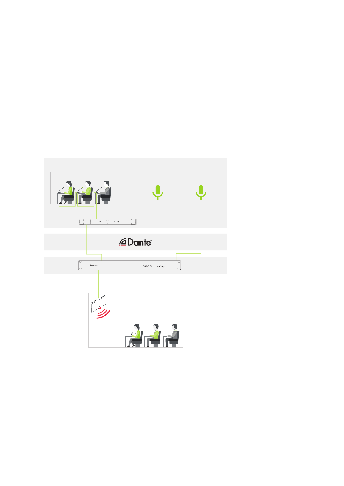
Lingua Infrared (IR) is Televic Conference's wireless solution for language distribution using infrared. You
can combine this system with Plixus engines or another third-party system to feed the floor and interpreter
audio to the Lingua IR. Link this audio source to the Lingua IR transmitter through a Dante™ connection.
The transmitter will send the audio signal to the radiators inside the room. The radiator will then send the
audio signal as infrared radiation to the receivers present in the room. These will then convert the radiation
back into an audio signal. Finally, with the receiver the participant can use which languages they wish to
hear.
Figure 1-1 A typical Lingua IR setup where one ore more audio sources (such as a conference system) are used to
feed audio into the infrared system. Participants present in the room can listen to the audio they want using the
receivers that pick up the infrared radiation.
AB O U T L ING U A I R 9
Page 10

Lingua IR consists out of four parts:
Lingua T (transmitter): accepts the audio signal from the conference system (for example
Plixus) and transmits the signal to the radiator(s). By default you can transmit up to 6 channels,
however additional licenses are available to transmit 12 (Lingua L12) or 40 channels (Lingua
L40).
Lingua RAD_H (radiator): distributes the signal throughout the conference venue.
Lingua Rx (receiver): allows attendees to select the language they want to hear the speaker
in. Three variants are available to receive 6, 12 or 40 channels.
Lingua CHC (charging case): case to charge and transport receivers in.
AB O U T L ING U A I R 10
Page 11

SAFETY INSTRUCTIONS
This chapter describes all safety instructions needed to use the Lingua IR system.
Read this before using the equipement.
Page 12

SAFETY INSTRUCTIONS
The safety instructions contain general safety guidelines that integrators, installers, operators, end users,
and anyone else who installs or uses Televic Conference material is required to read and follow at all times.
Safety
All Televic Conference systems are state of the art devices and have been designed to meet all quality
standards. Nevertheless, the individual components of the conference system can cause danger for persons
and material assets if
the conference system is not used as intended,
the conference system is set up by personnel not familiar with the safety regulations,
the conference system is converted or altered incorrectly,
the safety instructions are not observed.
FCC & ICES Information
(U.S.A and Canadian Models only).
This Class B digital apparatus complies with Canadian norm ICES-003.
Cet appareil numérique de la classe B est conforme à la norme NMB-003 du Canada.
This equipment has been tested and found to comply with the limits for a Class B digital device, pursuant to
Part 15 of the FCC Rules. These limits are designed to provide reasonable protection against harmful
interference in a residential installation. This equipment generates, uses and can radiate radio frequency
energy and, if not installed and used in accordance with the instructions, may cause harmful interference to
radio communications. However, there is no guarantee that interference will not occur in a particular
installation. If this equipment does cause harmful interference to radio or television reception, which can be
determined by turning the equipment off and on, the user is encouraged to try to correct the interference by
one or more of the following measures:
Reorient or relocate the receiving antenna
Increase the separation between the equipment and receiver
Connect the equipment into an outlet on a circuit different from that to which the receiver is
connected
Consult the dealer or an experienced radio/TV technician for help
SA F ETY INST RUC TIO NS 12
Page 13

Consult the Federal Communications Commission’s manual “How to Identify and Resolve
Radio-TV Interference Problems”
Operation is subject to the following two conditions:
1. This device may not cause harmful interference
2. This device must accept any interference received, including interference that may cause undesired
operation.
Changes or modifications made to this equipment not expressly approved by Televic Conference
may void the FCC authorization to operate this equipment.
Conformity And Certification Info For Japan
This device has been granted a designation number by Ministry of Internal Affairs and Communications
according to:
Ordinance concerning Technical Regulations Conformity Certification etc. of Specified Radio
Equipment (特定 無 線 設 備 の技術 基 準 適 合 証 明 等 に関する規 則 )
Article 2 clause 1 item 19/3
Approval No.:
202WW10120791/2
202XW10120791/2
This device should not be modified, otherwise the granted designation number will be invalid.
Important Safety Instructions
1.
Read Instructions. All the safety and operating instructions should be read before the product,
device or system is operated.
2.
Retain Instructions. The safety and operating instructions should be retained for future reference.
The instructions should be kept in the vicinity of the product or system.
3.
Heed Warnings. All warnings on the product and the operating instructions should be closely
adhered to.
4.
Follow Instructions. All instructions for installation or operating/use should be followed closely.
SA F ETY INST RUC TIO NS 13
Page 14

5.
Cleaning. Unplug this product from the wall outlet before cleaning. Do not use liquid cleaners or
aerosol cleaners. Use only a damp cloth for cleaning.
6.
Ventilation. Any slots and openings in the device or equipment are provided for ventilation and to
ensure reliable operation of the product and to protect it from overheating. These openings must
not be blocked or covered. The openings should never be blocked by placing the product on a chair,
table, rug, or other similar surface. This product should not be placed in a built-in installation such as
a bookcase or rack unless proper ventilation is provided or the manufacturer's instructions have
been adhered to.
7.
Heat. The product should be situated away from heat sources such as radiators, heat registers,
stoves, or other products (including amplifiers) that produce heat. Do not use or operate any
equipment in environments that exceed the standard operating temperatures.
8.
Modifications. Do not use any modifications, extension, or other attachments not recommended
by the product manufacturer as they may cause hazards.
9.
Accessories. Only use attachments/accessories specified by the manufacturer. Do not place this
product on an unstable cart, stand, tripod, bracket, or table. The product may fall, causing serious
injury to a child or adult, and serious damage to the product. Use only with a cart, stand, tripod,
bracket, or table recommended by the manufacturer, or sold with the product. Any mounting of the
product should follow the manufacturer's instructions, and should use a mounting accessory
recommended by the manufacturer.
10.
Water and Moisture. Do not use this product near water or in a humid environment.
11.
Moving. A product and cart combination should be moved with care. Quick stops, excessive force,
and uneven surfaces may cause the product and cart combination to overturn.
12.
Power Sources. This product should be operated only from the type of power source indicated on
the marking label. If you are not sure of the type of power supply of your room, consult your product
dealer or local power company. For products intended to operate from battery power, or other
sources, refer to the operating instructions.
13.
Power Lines. An outdoor system should not be located in the vicinity of overhead power lines or
other electric light or power circuits, or where it can fall into such power lines or circuits. When
installing an outdoor system, extreme care should be taken to keep from touching such power lines
or circuits, as contact with them might be fatal. U.S.A. models only - refer to the National Electrical
Code Article 820 regarding installation of CATV systems.
14.
Grounding or Polarization. Do not defeat the safety purpose of the polarized or ground-type
plug. A polarized plug has two blades with one wider than the other. A grounding type plug has two
blades and a third grounding prong. The wider blade or the third prong are provided for your safety.
SA F ETY INST RUC TIO NS 14
Page 15

If the provided plug does not fit into your outlet, consult an electrician for replacement of the
obsolete outlet.
15.
Power-Cord Protection. Power-supply cords should be routed to that they are not likely to be
walked on or pinched by items placed upon or against them, paying particular attention to cords at
plug, convenience receptacles, and the point where they exit from the product.
16.
Lightning. For added protection for this product during a lightning storm, or when it is left
unattended and unused for long periods of time, unplug it from the wall outlet. This will prevent
damage to the product due to lightning and power-line surges. (Not applicable when special
functions are to be maintained, such as evacuation systems.)
17.
Overloading. Do not overload wall outlets, extension cords or integral convenience receptacles as
this can result in a risk of fire or electric shock.
18.
Object and Liquid Entry. Never push objects of any kind into this product through openings as
they may touch dangerous voltage points or short-out parts that could result in a fire or electric
shock. Never spill liquid of any kind on the product.
19.
Inflammable and Explosive Substance. Avoid using this product where there are gases, and
also where there are inflammable and explosive substances in the immediate vicinity.
20.
Heavy Shock or Vibration. When carrying this product around, do not subject the product to
heavy shock or vibration.
21.
Servicing. Do not attempt to service this product yourself as opening or removing covers may
expose you to dangerous voltage or other hazards. Refer all servicing to qualified service personnel.
22.
Damage Requiring Service. Unplug this product from the wall outlet and refer servicing to
qualified service personnel under the following conditions:
a. When the power-supply cord or plug is damaged.
b. If liquid has been spilled, or objects have fallen into the product.
c. If the product has been exposed to rain or water.
d. If the product does not operate normally by following the operating instructions. Adjust
only those controls that are covered by the operating instructions as an improper
adjustment of other controls may result in damage and will often require extensive work
by a qualified technician to restore the product to its normal operation.
e. If the product has been dropped or damaged in any way.
f. When the product exhibits a distinct change in performance-this indicates a need for
service.
SA F ETY INST RUC TIO NS 15
Page 16

23.
Replacement Parts. When replacement parts are required, be sure the service technician has used
replacement parts specified by the manufacturer or have the same characteristics as the original
part. Unauthorized substitutions may result in fire, electric shock, or other hazards.
24.
Safety Check. Upon completion of any service or repairs to this product, ask the service technician
to perform safety checks to determine that the product is in proper operating condition.
25.
Coax Grounding. If an outside cable system is connected to the apparatus, be sure the cable
system is grounded. U.S.A. models only: Section 810 of the National Electrical Code, ANSI/NFPA
No.70-1981, provides information with respect to proper grounding of the mount and supporting
structure, grounding of the coax to a discharge apparatus, size of grounding conductors, location of
discharge unit, connection to grounding electrodes, and requirements for the grounding electrode.
26.
Eye exposure. Beware of permanent eye damage due to the infrared radiation. Permanent
exposure is allowed at a distance of 50cm (E=100W/m² limit according to IEC62471 2006-2007
first edition). At distances below 10 cm (=for servicing, installation testing), limit is reached after 20
to 30 seconds. Take precautions : cover the LEDs during servicing/testing and limit the exposure
time. Avoid looking directly into the LEDs and limit the exposure time. At distances between 10 to
50 cm : avoid looking directly into the LEDs and limit the exposure time.
Lithium Batteries
DANGER
ELECTRICAL MISUSAGE
Only use the dedicated charging case to charge the battery
Do not charge the battery by an electric outlet directly or a cigarette lighter charger
Do not charger the battery reversely
ENVIRONMENTAL MISUSAGE
Do not leave the battery near the fire or a heated source.
Do not throw the battery into the fire.
Do not leave, charge or use the battery in a place where the inside temperature may be over
60°C
Do not immerse, throw or wet the battery in water
SA F ETY INST RUC TIO NS 16
Page 17

OTHER
Do not fold the battery cased with laminated film such as pouch and Polymer.
Do not store the battery in a pocket or a bag together with metallic objects such as keys,
necklaces, hairpins, coins, or screws.
Do not short circuit (+) and (-) terminals with metallic object intentionally.
Do not pierce the battery with a sharp object such as a needle, screw drivers.
Do not heat partial areas of the battery with heated objects such as soldering iron.
Do not hit battery with heavy objects such as a hammer.
Do not step on the battery and throw or drop the battery on a hard floor to avoid mechanical
shock.
Do not disassemble the battery or modify the battery design including electric circuit.
Do not solder on the battery directly.
Do not use seriously scared or deformed battery.
Do not put the battery into a microwave oven, dryer ,or high-pressure container.
Do not use or assemble the battery with other makers' batteries, different types and/or models
of batteries such as dry batteries, nickel-metal hydride batteries, or nickel-cadmium batteries.
Do not use or assemble old and new batteries together.
WARNING
Stop charging the battery if charging isn't completed within the specified time.
Stop using the battery if the battery becomes abnormally hot, order, discoloration, deformation,
or abnormal conditions is detected during use, charge, or storage.
Keep away from fire immediately when leakage or foul odors are detected. If liquid leaks onto
your skin or cloths, wash well with fresh water immediately.
If liquid leaking from the battery gets into your eyes, don't rub your eyes and wash them with
clean water and go to see a doctor immediately.
If the terminals of the battery become dirty, wipe with a dry cloth before using the battery.
SA F ETY INST RUC TIO NS 17
Page 18

The battery can be used within the following temperature ranges. Don't exceed these ranges.
Charge temperature ranges : 0℃ ~ 45℃
Discharge Temperature ranges : -20℃ ~ 60℃
Store the battery at temperature below 60℃
Cover terminals with proper insulating tape before disposal.
CAUTION
ELECTRICAL MISUSAGE
Battery must be charge with constant current-constant voltage (CC/CV).
Charge current must be controlled by specified value in Cell specification.
Cut-off Voltage of charging must be 4.2V.
OTHERS
Charger must stop charging battery by detecting either charging time or current specified in
Cell’s specification.
Discharge current must be controlled by specified value in Cell’s specification.
Cut-off Voltage of discharging must be over 2.5V.
Before using the battery or charging case, read the user manual and precaution of it's handling.
Replace the battery when using time of battery becomes much shorter than usual.
Cover terminals with insulating tape before proper disposal.
If the battery is needed to be stored for an long period, battery should be removed from the
application and stored in a place where humidity and temperature are low.
While the battery is charged, used and stored, keep it away from object materials with static
electric chargers.
Power Connections
For permanently connected equipment, a readily accessible disconnect device shall be incorporated in the
fixed wiring; For pluggable equipment, the socket-outlet shall be installed near the equipment and shall be
easily accessible.
SA F ETY INST RUC TIO NS 18
Page 19
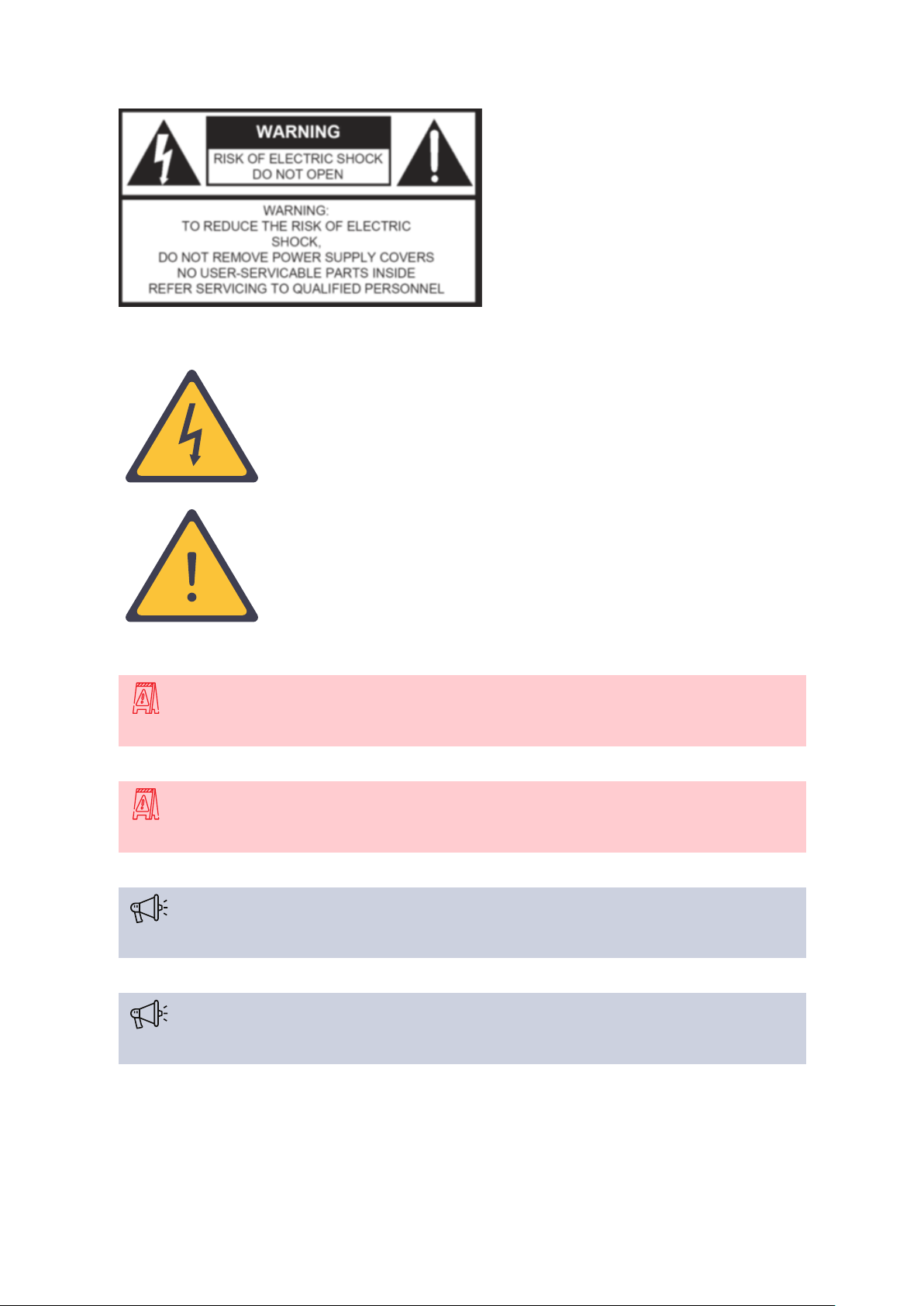
This label may appear on the bottom of the apparatus due to space limitations.
The lightning flash with an arrowhead symbol, with an equilateral triangle, is intended
to alert the user to the presence of un-insulated ‘dangerous voltage’ within the
products enclosure that may be of sufficient magnitude to constitute a risk of electric
shock to persons.
The exclamation mark within an equilateral triangle is intended to alert the user to the
presence of important operating and maintenance (servicing) instructions in the
literature accompanying the appliance.
To reduce the risk of fire or electric shock, do not expose this appliance to rain or moisture. Do not
open the cabinet; refer servicing to qualified personnel only.
To prevent electric shock, do not use this (polarized) plug with an extension cord receptacle or
other outlet unless the blades can be fully inserted to prevent blade exposure.
Installation should be performed by qualified service personnel only in accordance with the
National Electrical Code or applicable local codes.
Installation should be performed by qualified service personnel only in accordance with the
National Electrical Code or applicable local codes.
SA F ETY INST RUC TIO NS 19
Page 20

LINGUA IR COMPONENTS
A Lingua IR setup consists of four elements: the transmitter, radiators, receivers and
a charging case. This chapter will describe these hardware components together
with how you can use these components to match your needs.
Page 21
LINGUA IR TRANSMITTER
DANGER
™
! !
1
2
4
3
5 6 7
8
9
11
10
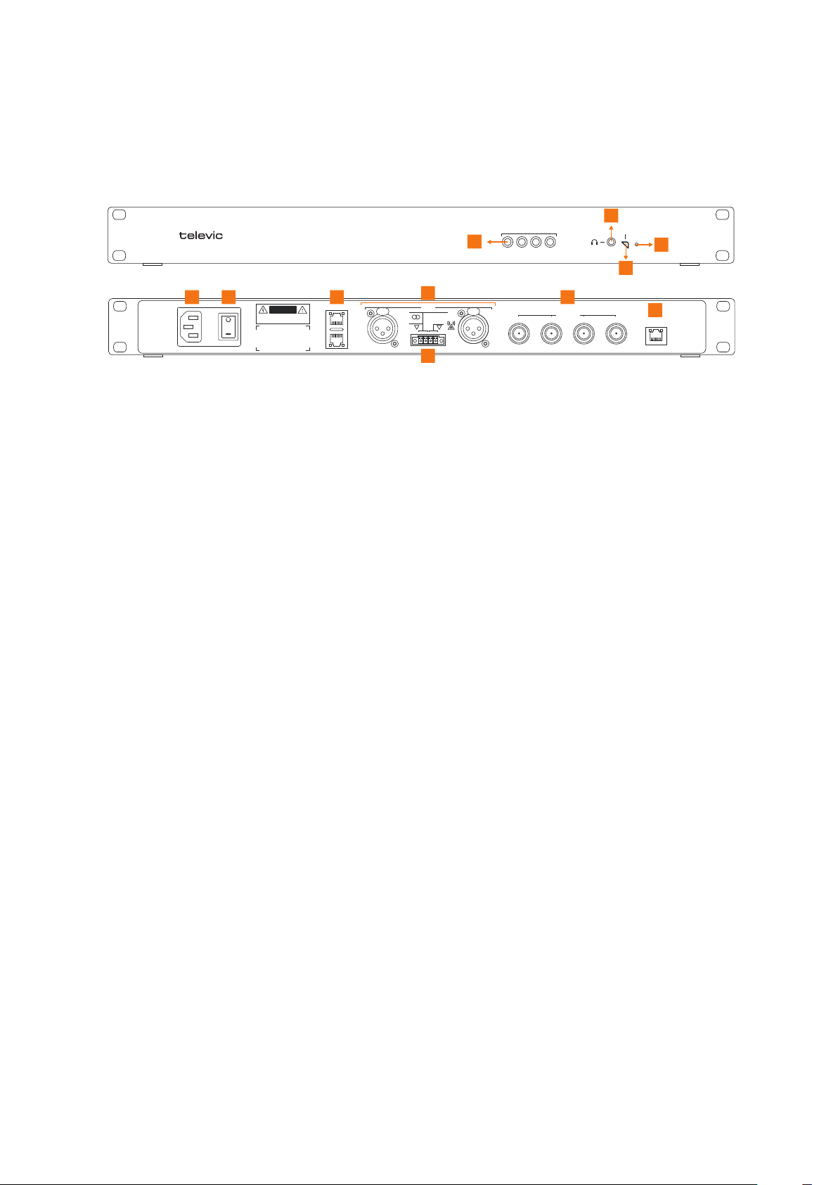
Overview
Figure 1-2 Front and back view of Lingua IR transmitter
1.
Transmitter status LED: shows the current status of the transmitter
2.
Headphone connector: plug in headphone to check all audio input (audio over Dante™ and
audio from the auxiliary audio inputs). Select the channel and adjust the volume using the web
server.
3.
Monitoring Infrared LEDs: LED lights transmitting the same IR signal as the radiator, this allows
you to monitor the transmitted audio using a Lingua IR receiver.
4.
Reset button: different reset options are available see "Reset the Lingua IR transmitter" on the
next page for more information.
5.
Mains connection: with fuse and spare fuse
6.
On/Off switch
7.
Dante™ signal input: interface to connect the transmitter to a conference system. The primary
connector is marked by "1" and the secondary by "2"(use for redundancy).
8.
Auxiliary audio inputs: connect with audio installation (left) or emergency system (right).
9.
Emergency/Override switch connector: Close the left switch to override the audio on all output
channels, use right switch to broadcast emergency signal on all output channels. If both switches
are closed the emergency signal has priority.
10.
Radiator connector: four BNC output connectors to connect the transmitter to the radiators.
11.
LAN connector: use LAN connection to configure the transmitter settings using the web server.
LIN G UA I R T RAN SMIT TER 21
Page 22
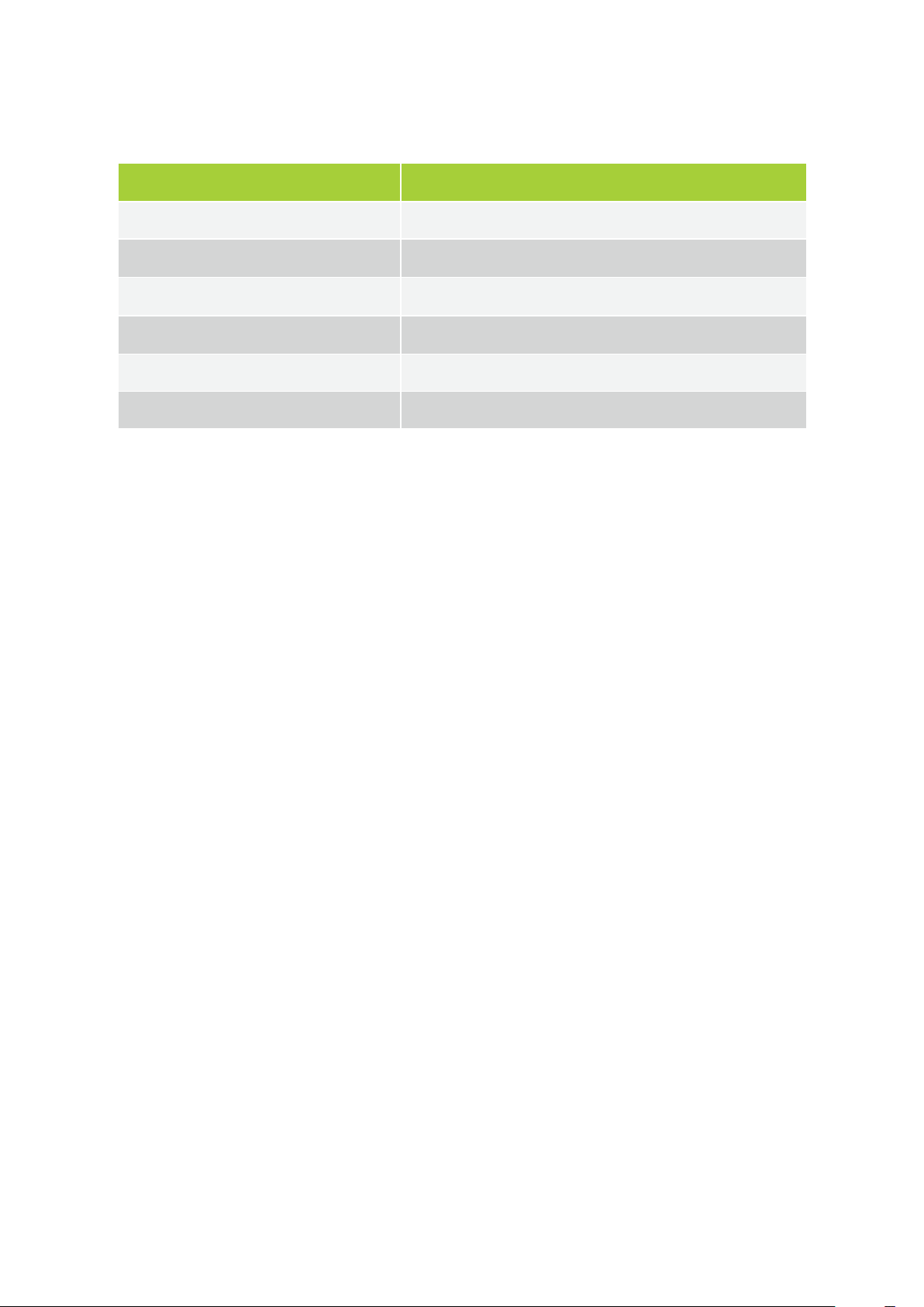
Transmitter Status LED Meaning
LED status Meaning
White During startup
Green System operating normally
Blinking blue Updating system
Blinking green Emergency
Red Indicates an error
Yellow Fallback mode
Reset The Lingua IR Transmitter
There is a reset button on the transmitter that allows you to reset specific settings depending on the reset
procedure you perform:
RESET NETWORK SETTINGS:
When the status LEDis green (after power-up), you can reset the network settings back to 192.168.0.140
with subnet mask 255.255.255.0. Press and hold the reset button until the status LED changes to red
(approximately 10 seconds). After you release the reset button, the transmitter will reboot with the default
network settings.
FACTORY RESET
When you perform a factory reset you reset network settings and all configurations. Press and hold
the reset button before switching on the power of the transmitter. Hold the reset button until the status
LED turns blue. Release the reset button to reboot the transmitter in fallback mode.
In fallback mode, the web server will have reduced functionalities. You are only able to upload an update
file. After reboot, the web server will have all functionalities again. Now, upload the update file again to
complete the update process of the firmware. After the final reboot, you can create new configurations.
LIN G UA I R T RAN SMIT TER 22
Page 23
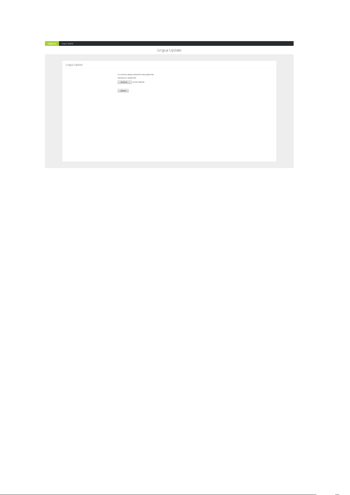
Figure 1-3 The transmitter web server in fallback mode
LIN G UA I R T RAN SMIT TER 23
Page 24
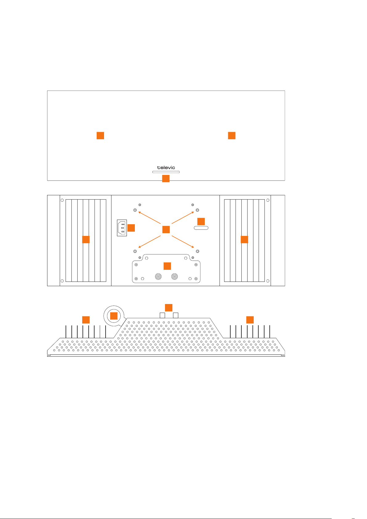
LINGUA IR RADIATOR
1
22
4
7 7
6
5
6
3
4
77
Overview
Figure 1-4 Front, back, and top view of Lingua IR radiator
1.
Status LED: consists of three multicolor LED lights that show the radiator status and other radiator
related information.
2.
Infrared LEDs: the LED lights that transmit the IR signal. Adjust the intensity by changing the power
settings.
3.
Mains connector
LIN G UA I R R A DIATO R 24
Page 25
4.
IR signal connector: connect to transmitter or other radiator using a RG59 coax cable with BNC
connectors.
5.
VESA mounting holes: compatible with all VESA 100×100 mounts
6.
Safety eye: for additional security to mount the radiator
7.
Cooling fins: to cool the radiator during usage
Radiator Power Levels
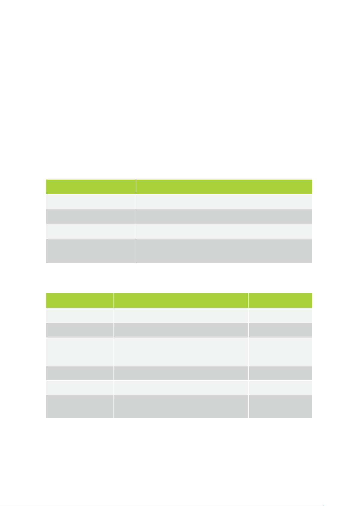
The Lingua IR radiator has four different power modes, which you can set using the web server. You can use
different power levels to increase the life span of the infrared LEDs (by reducing the power level) or to
increase the range of your infrared signal (by increasing the power level). The following power levels are
available:
Power level Description
Power off No power
Reduced power Power at 33% of its maximum capacity
Normal power Power at 66% of its maximum capacity
Boost power Power at 100% of its maximum capacity. Beware that when you use the
radiator at this power level this reduces the life span of the infrared LEDs.
Radiator LED Status Meaning
LED status Meaning Remark
Middle LED red Power OK, but there is no signal
Middle LED Green Power on, signal present
Middle LED Orange
Middle LED blue Calibration started
Right LED green Calibration successful
Right LEDred Calibration failed All IR LEDs are forced to
Power on, signal present
Synchronization error
power off
LIN G UA I R R A DIATO R 25
Page 26

LED status Meaning Remark
Left LEDred Temperature error All IR LEDs are forced to
power off
Left LEDgreen No temperature error, less than three IR diode lines
defective
Left LEDorange Three or more IR diode lines defective
Board defective
LIN G UA I R R A DIATO R 26
Page 27
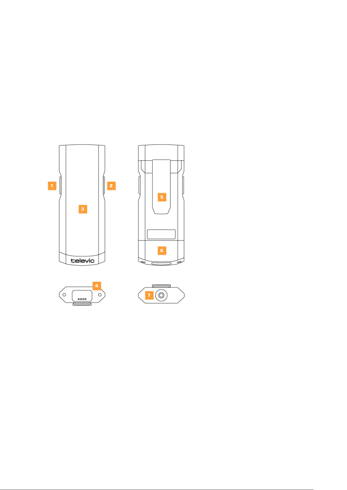
LINGUA IR RECEIVER
With the receiver you can listen to the audio transmitted by the radiator. Depending on your license you can
receive six, twelve or forty channels. The receiver has 270° wide reception angle and needs no
configuration to use. With the clip available on the back, you can easily attach the receiver to your clothes
while keeping your hands free.
When you plug in the headphone, the receiver automatically switches on.
Overview
Figure 1-5 The Lingua IR receivers
1.
Volume control: Use the up or down buttons to adjust the volume accordingly.
2.
Channel selector: press the up and down buttons to switch between channels.
3.
LCD display: shows the ISO code of the selected language and channel number. Additional
information can be displayed when you press and hold different button combinations. See note for
more information.
4.
Charging contacts: these need to be aligned correctly with the contacts in the charging case to
charge correctly.
LIN G UA I R R ECE IV ER 27
Page 28
5.
Clip: use the clip to attach the receiver to your clothes or belts.
6.
Battery: to change the battery, unfasten the screws at the bottom of the receiver.
7.
Headphone connector: plug in the headphone to switch on the receiver.
Keep the top part of the receiver free at all times. This part holds the infrared sensitve diode and
placing objects (like stickers or headphone cords) on top of the LED will block the infrared signal
and prevent you from receiving the audio.
For optimal reception of the IR signal, aim the back of the receiver towards the radiator. All
objects between the receiver and the radiator will block the infrared signal from reaching the
receiver.
When you press different buttons at the same time you can see additional information on the
receiver screen. The following combinations are possible:
> For application, bootloader, VHDL and hardware version: press and hold the top buttons
on each side of the receiver and plug in the headphone.
> For logging: press and hold the top button on one side and the bottom button on the other side
and plug in the headphone. Press the right button to reset the logging
Receiver Variants
Different variants are available for the Lingua IR receiver with different amounts of channels. The amount of
channels is hard coded into the devices, which means you cannot upgrade the receiver when you need
additional channels.
Receiver Information
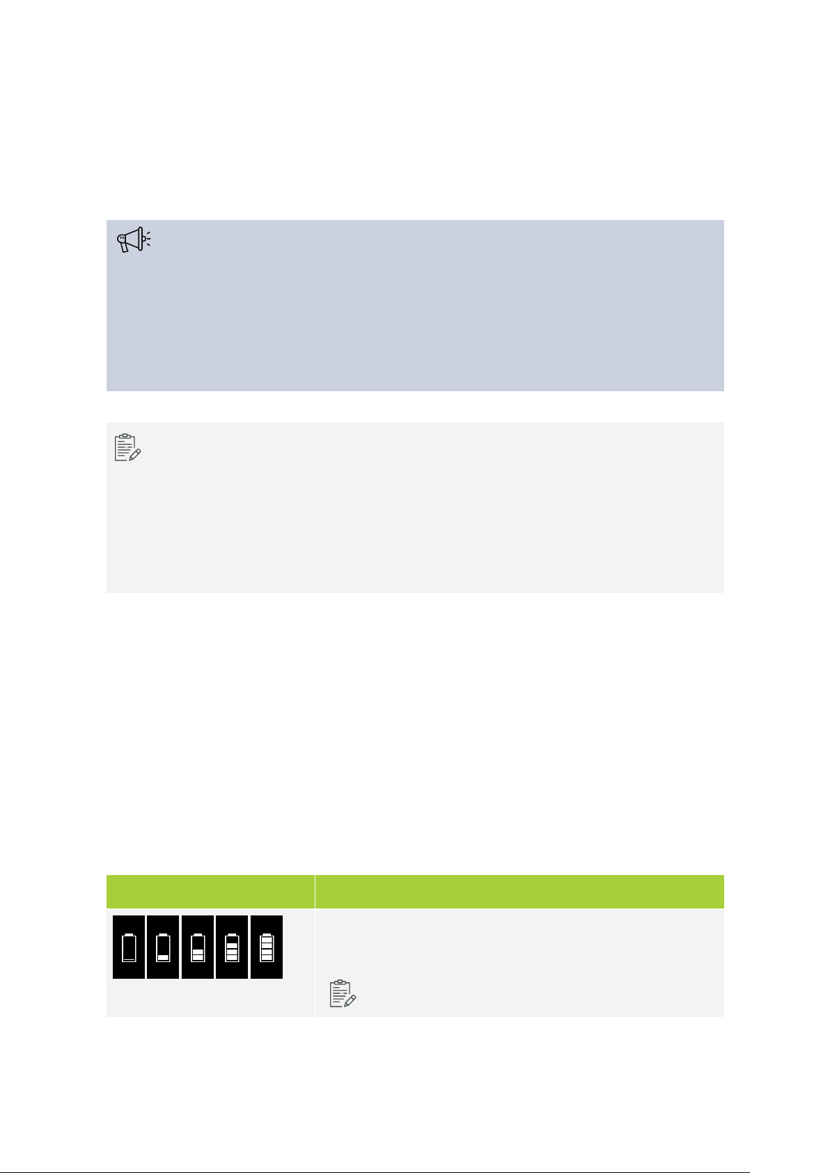
On the OLED screen of the receiver different information can be displayed. You can see the channel and
the language (ISO) , and the volume of the receiver. There are also different icons availabe that have a
specific meaning:
Icon Description
Shows the remaining battery life of the receiver (5%, 25%, 50%,
75%, 100%).
The receiver will indicate when the battery is almost empty
LIN G UA I R R ECE IV ER 28
Page 29
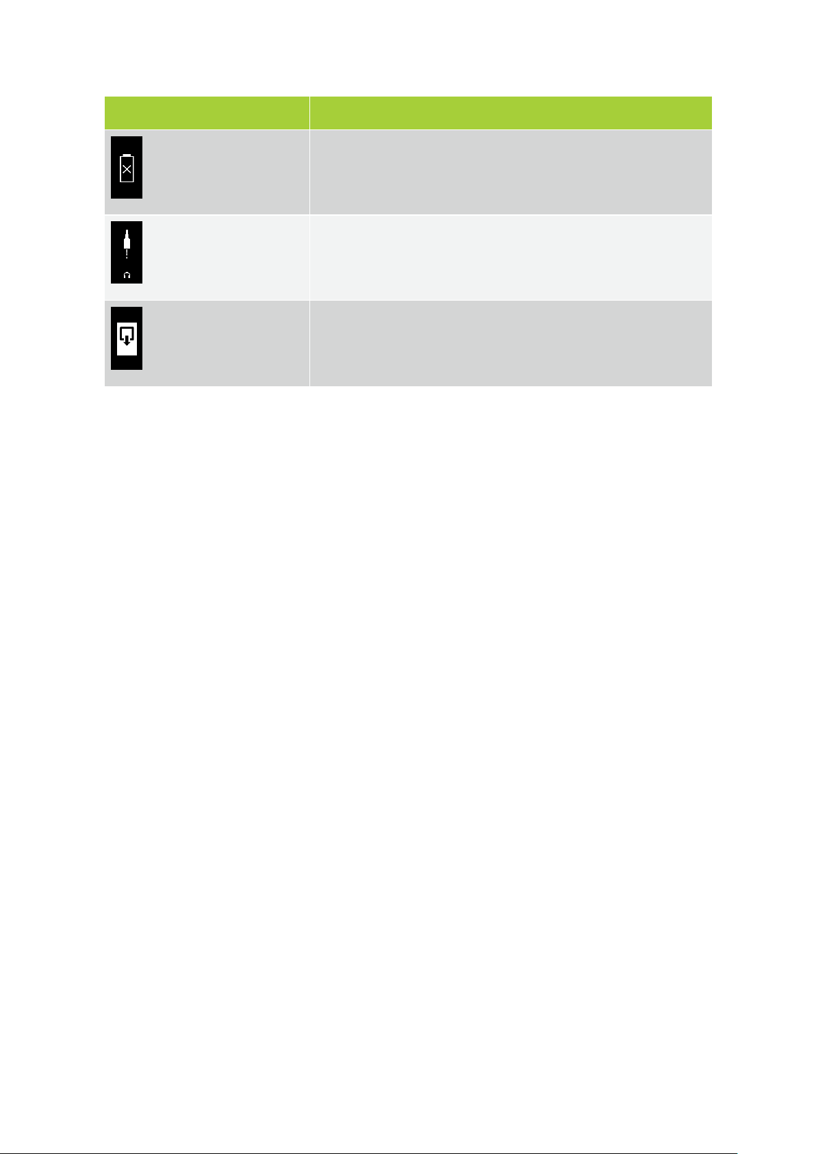
Icon Description
Problem with fuel gauge of battery: it is notpossible to see the battery
life of the receiver.
Remove the battery and insert it gain to solve the problem.
Plug in the headphone
The emergency signal is being broadcast
LIN G UA I R R ECE IV ER 29
Page 30
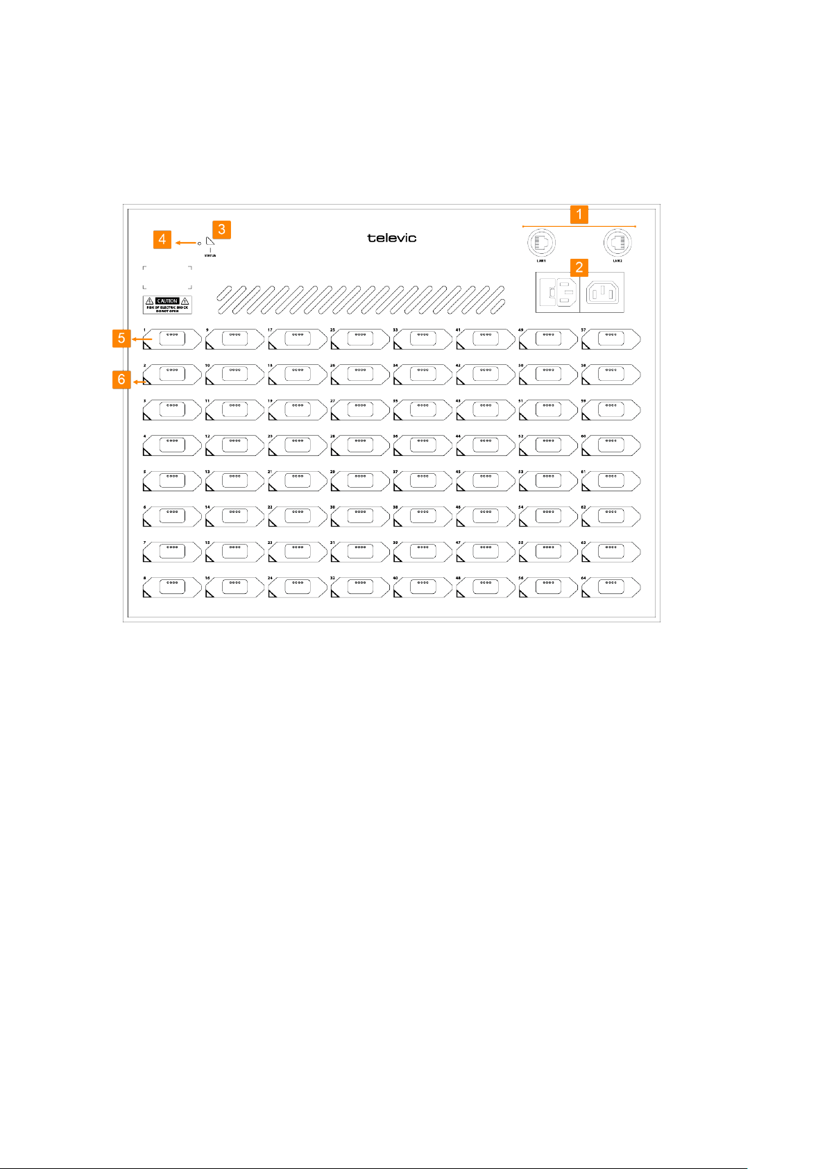
LINGUA CHARGING CASE
Overview
Figure 1-6 Lingua IR charging case
1.
LAN connection: two connections to daisy chain multiple charging cases and to configure the
charging case and receiver settings using the web server.
2.
Two mains connectionsfor loop through. You can daisy chain up to three charging cases when
using 125V or maximum of six for 230V.
3.
Status LED: shows the status of the Lingua IR charging case.
4.
Reset button: different reset options are available see "Reset the Lingua IR Charging Case" on the
next page for more information.
5.
Receiver slot: positions in the case to charge and update Lingua IR receivers.
6.
Receiver LED: indicates the status of the receiver.
LIN G UA C HAR G ING CASE 30
Page 31
You can use multiple charging cases in one setup. Simply connect the different charging cases
using the LAN connection provided on the case.
Charging Case Status LED Meaning
LED status Meaning
Green Normal operating system
Blinking blue Updating receivers or charging case
Red Indicates an error
Yellow fallback mode
Charging Case Receiver LEDMeaning
LED status Meaning
Blinking green The receiver is charging
Green The receiver is fully charged and functional
Blue Indicates the receiver is updating
Red Indicates that there is something wrong with the receiver, go to
the receiver web server to see the type of error.
Reset The Lingua IR Charging Case
There is a reset button on the charging case that allows you to reset specific settings depending on the reset
procedure you perform:
RESET NETWORK SETTINGS:
When the status LEDis green (after power-up), you can reset the network settings back to 192.168.0.150
with subnet mask 255.255.255.0. Press and hold the reset button until the status LED changes to red
(approximately 10 seconds). After you release the reset button, the charging case will reboot with the
default network settings.
LIN G UA C HAR G ING CASE 31
Page 32

FACTORY RESET
When you perform a factory reset you reset network settings and all configurations. Press and hold
the reset button before switching on the power of the charging case. Hold the reset button until the
status LED turns blue. Release the reset button to reboot the charging case in fallback mode.
In fallback mode, the web server will have reduced functionalities. You are only able to upload an update
file. After reboot, the web server will have all functionalities again. Now, upload the update file again to
complete the update process of the firmware. After the final reboot, you can create new configurations.
LIN G UA C HAR G ING CASE 32
Page 33

INSTALLATION DESIGN
This chapter describes how to set up the installation of the Lingua IR system before
you can physically install it. You will find more information on the technical details
of the different components and how to combine and configure them.
Page 34
GENERAL INFRARED GUIDELINES
270°
Rules And Standards
The Lingua IR systems conforms to IEC 61603 part 7 (for 24 channels), the international standard for digital
infrared transmission of audio signals for conference use and similar applications.
Infrared Bands And Channels
The Lingua IR system can use a maximum of ten infrared bands, each band can have up to four
channels. The maximum amount of channels on your system depends on the license you have (6, 12 or 40
channels).
Infrared Influencing Elements
SENSITIVITY OF THE RECEIVER
The positioning of the receiver relative to the radiator(s) has an effect on how efficiently you will receive a
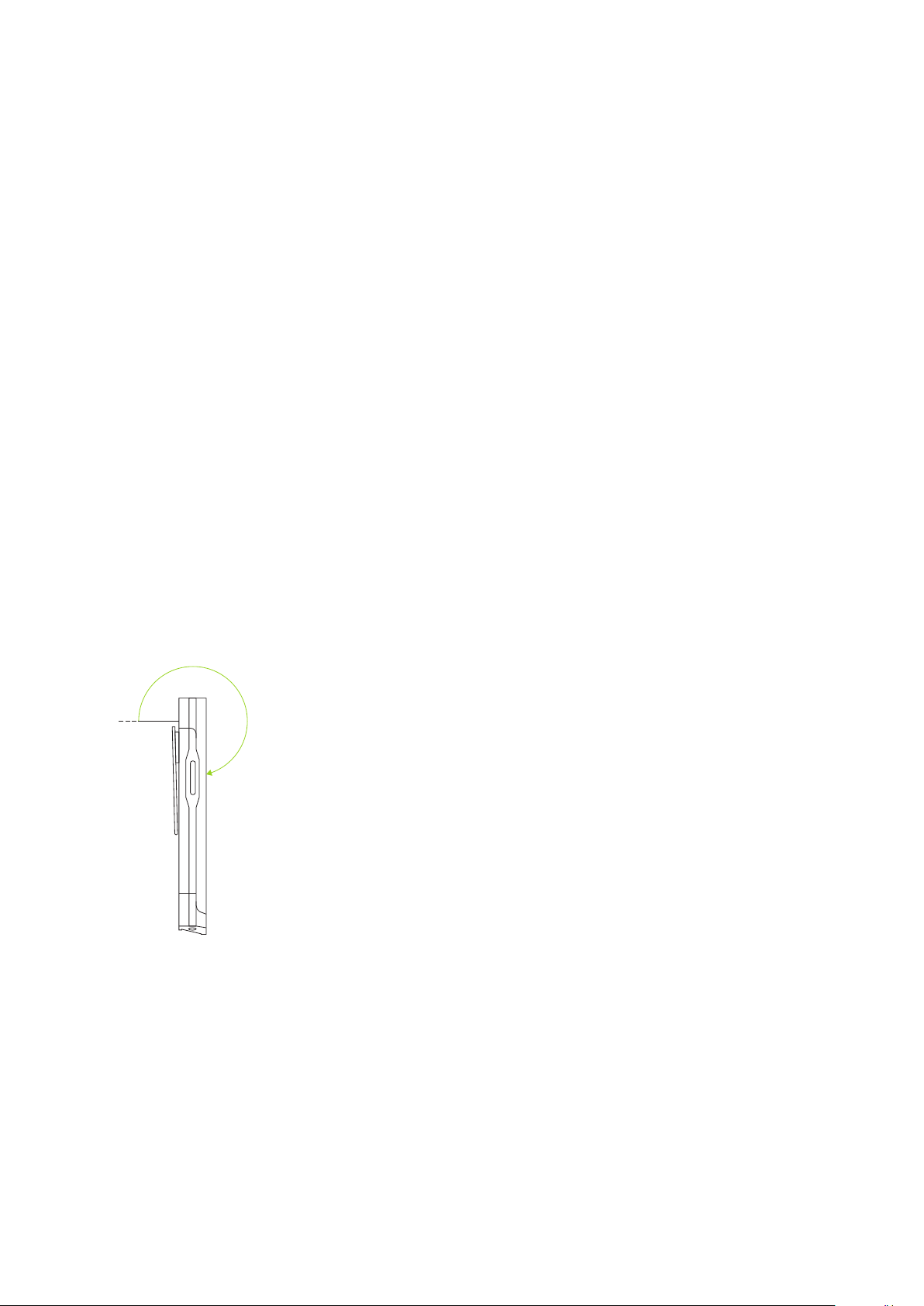
signal. For maximum sensitivity aim the back side of the receiver (the side with the clip) directly towards the
radiator. When you tilt the receiver this will reduce the sensitivity of the receiver. The receiver has a 270°
wide reception angle.
Figure 1-7 The reception angle of the Lingua IR receiver
AMBIENT LIGHTING
Ambient lighting can disturb the distribution of the infrared signal. For this reason the Lingua IR system
should not be used in outdoor conditions or in rooms with very bright lightning.
GEN ERA L INFRA R ED G U ID ELIN ES 34
Page 35
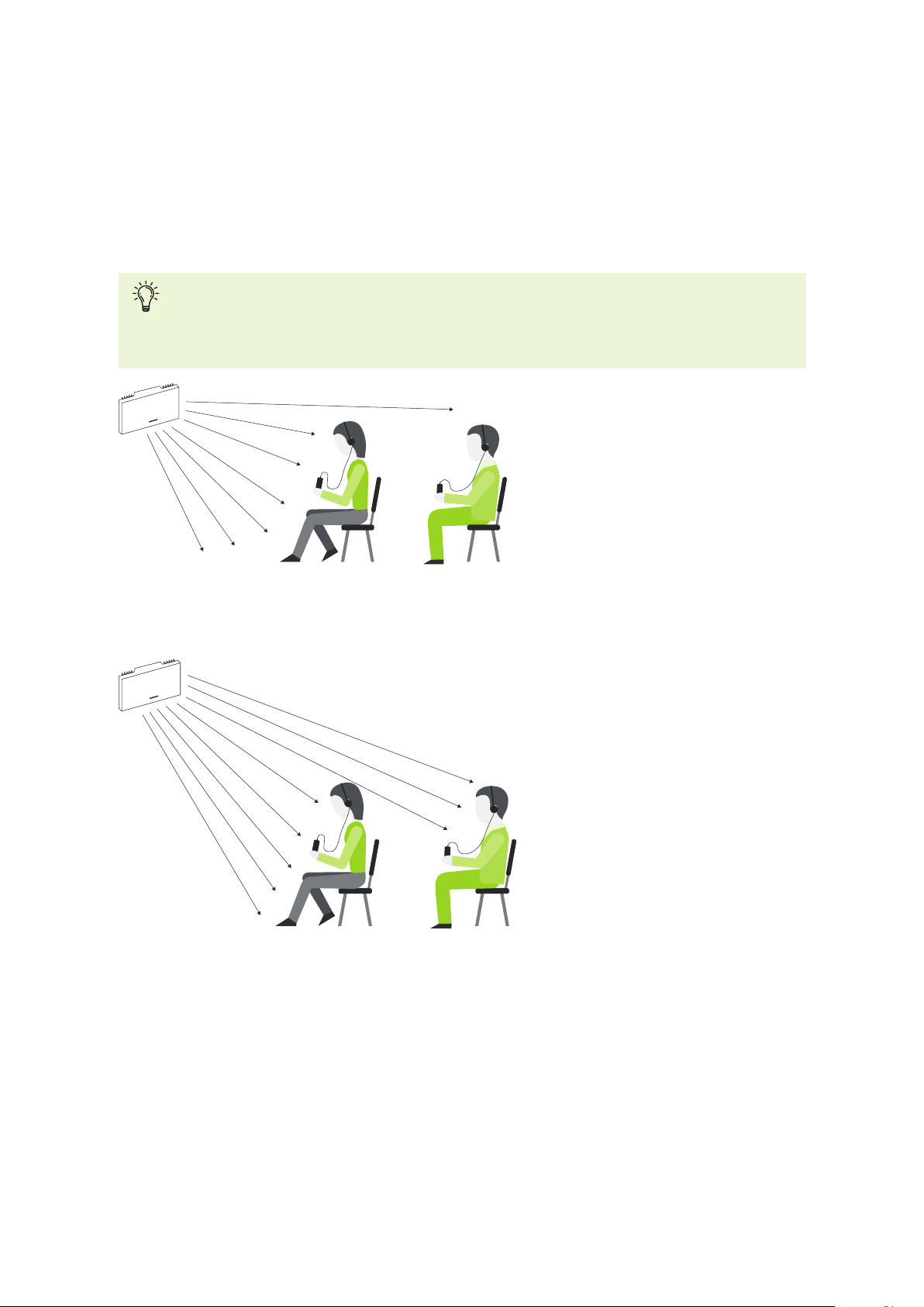
VENUE PROPERTIES AND RADIATOR POSITION
Different elements present in the room can effect the infrared signal transmission. Most objects reflect
infrared, with the exception of dark and rough surfaces that absorb a large portion of the infrared signal.
Infrared will not pass trough objects that are opaque to visible light, therefore it is important to position your
radiators carefully.
Do not put objects between the radiator and the receivers because this will hinder the infrared
signal. This also applies to people, the radiation will not pass through people. Therefore you should
position enough radiators at the correct locations inside the venue for optimal coverage.
Figure 1-8 Effect of positioning the radiator too low, preventing people sitting in further rows from picking up
the infrared signal
Figure 1-9 Correct position of the radiator, participants on all rows can pick up the infrared signal
If the venue permits it, the receiver can pick up reflected infrared radiation as well as direct radiation. The
radiation can be reflected by the wall, floor or other objects present in the room.
GEN ERA L INFRA R ED G U ID ELIN ES 35
Page 36
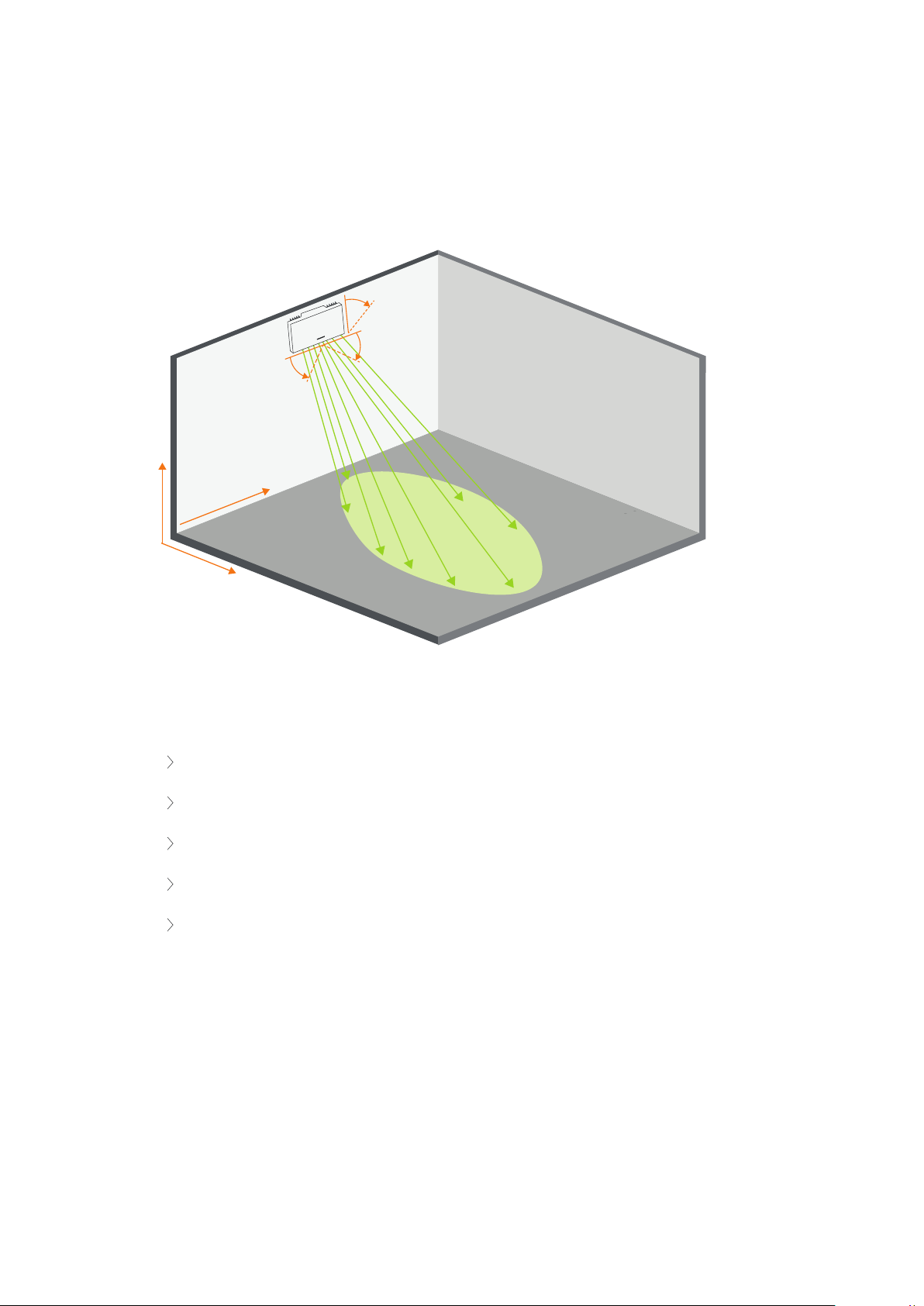
Footprint Of The Radiator
Length
Width
Vertical
angle
Horizontal
angle
Height
Every radiator has a certain reach. This is the area that can receive the infrared radiation, this is called the
footprint of the radiator. The footprint of the radiators depends on the position of the radiator as well as the
amount of channels used.
Figure 1-10 The footprint of the radiator and the physical parameters that influence the footprint
The position of the radiator is determined by the following parameters:
The x position in the room
The y position in the room
The height of the mounted radiator
The vertical angle: how the radiator is tilted
The horizontal angle: the angle the radiator is turned left or right
For a detailed description of how these parameters effect the footprint see "Position the Lingua IR
components" on page38.
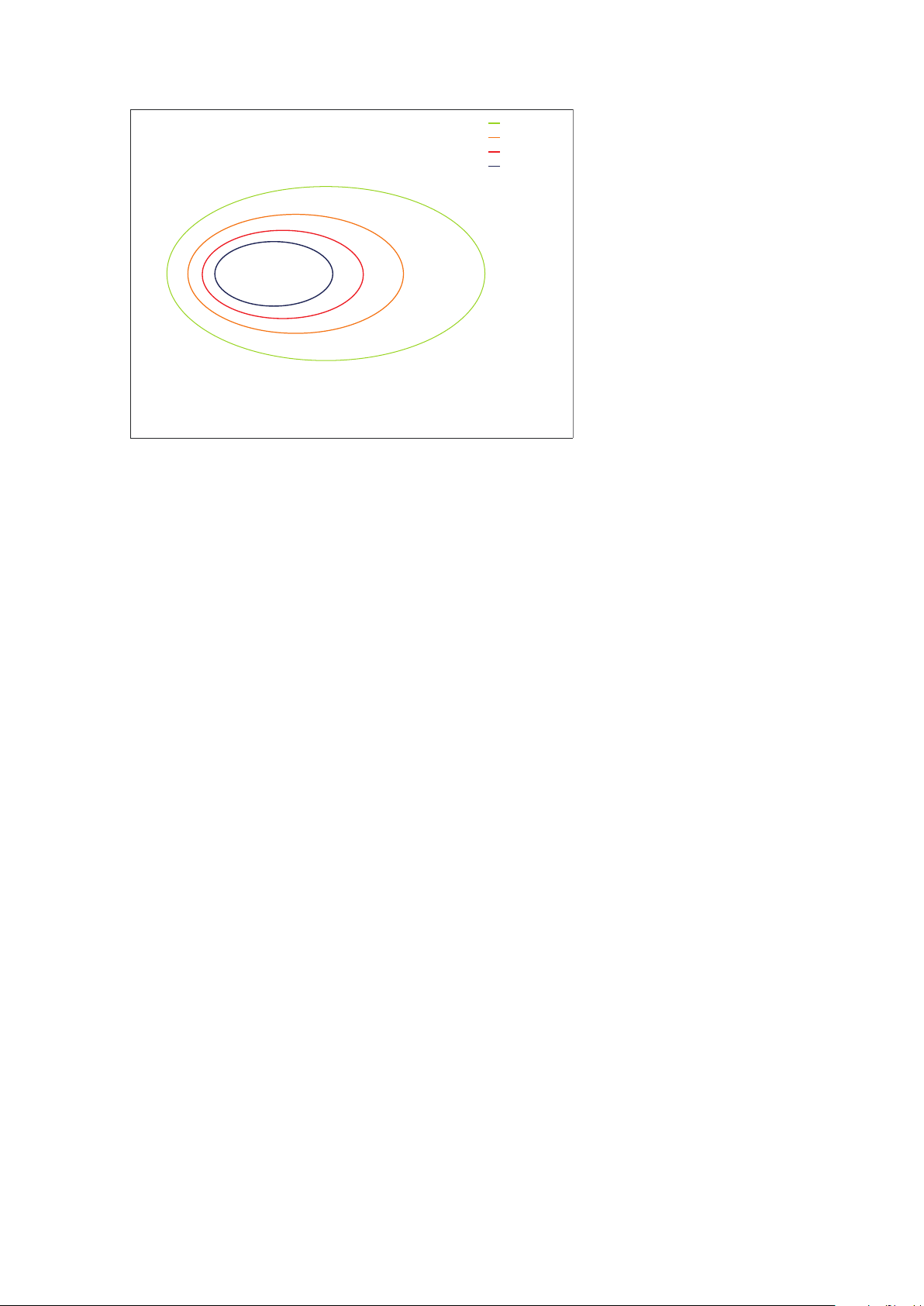
The amount of channels can also change the footprint of the radiator. When you have more than four,
eight, twelve, etc. channels, this will drastically reduce the size of the radiator footprint.
GEN ERA L INFRA R ED G U ID ELIN ES 36
Page 37
4 channels
5 channels
9 channels
13 channels
Room Length
Room Width
Figure 1-11 The effect of the amount of channels on the footprint of the radiator
OVERLAPPING FOOTPRINTS
When there are multiple radiators in a room, the footprints of the different radiators can overlap. If these
radiators are connected to the transmitter with cables having different lengths then the signal will reach the
radiators at a different time. This mismatch will results in the reduction or canceling of the infrared signal (in
places where the IR signal of the radiatiors have equal strength), thus creating black spots. For more
information see
GEN ERA L INFRA R ED G U ID ELIN ES 37
Page 38
POSITION THE LINGUA IR COMPONENTS
Lingua IR Radiator Position
The position of the radiators is very important for a successful set up. Depending on the layout of your room,
the radiators need to be set up in different places of the room. Below you can find some examples of
different setups and the position of the radiators.
To see the effect of the position and angle of all radiator on the footprint of the radiators and the IR
reception in the room, use the calculator tool. You can find the calculator on Sharefile in the folder
TCS-Marketing > Public > Technical Documentation > Calculators.
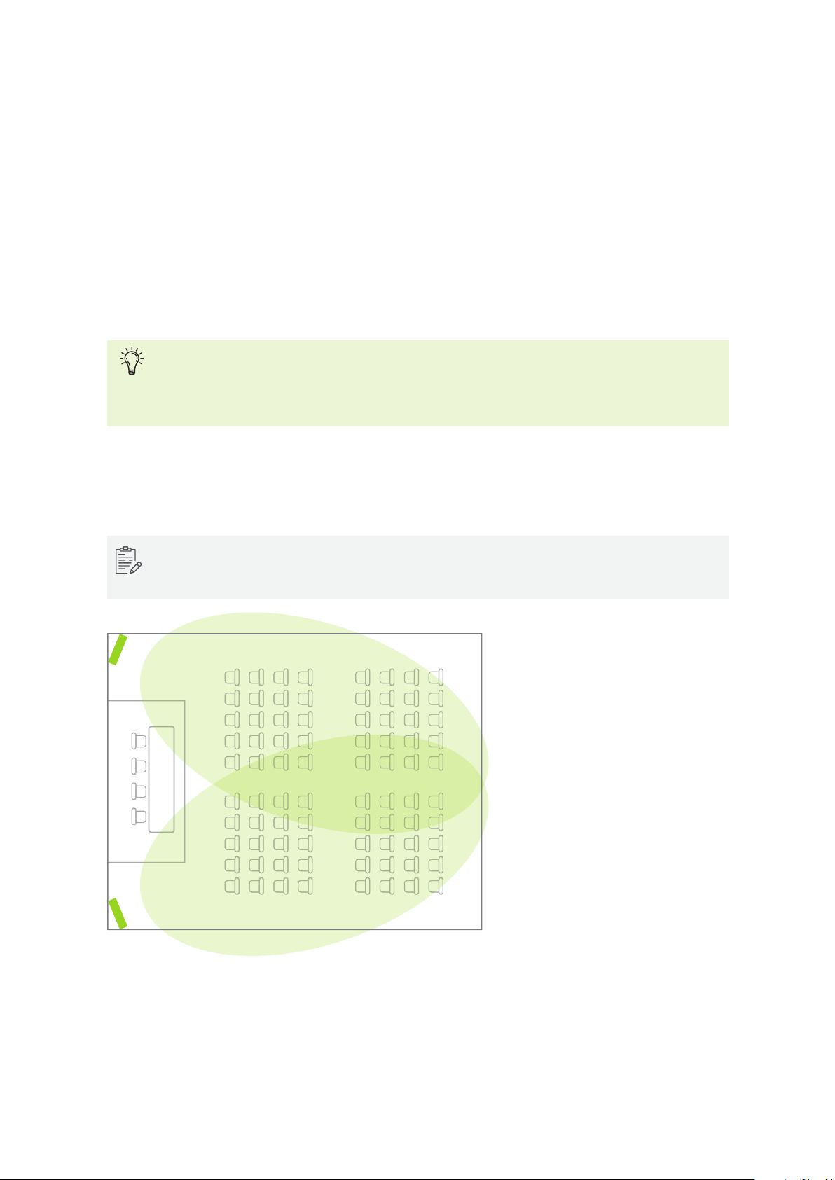
In the first example all seats are pointing towards the stage in the same direction. In order for everyone to
receive the infrared signal, you need to place two radiators in two corners of the room to cover the entire
room (by reflected and direct radiation).
When the length of the cables from the transmitter to the radiators differs, then this difference
should be corrected using the automatic delay line calibration.
Figure 1-12 Conference setup with all chairs pointing in the same direction
PO S IT IO N THE L ING UA IR C O MPO NEN TS 38
Page 39
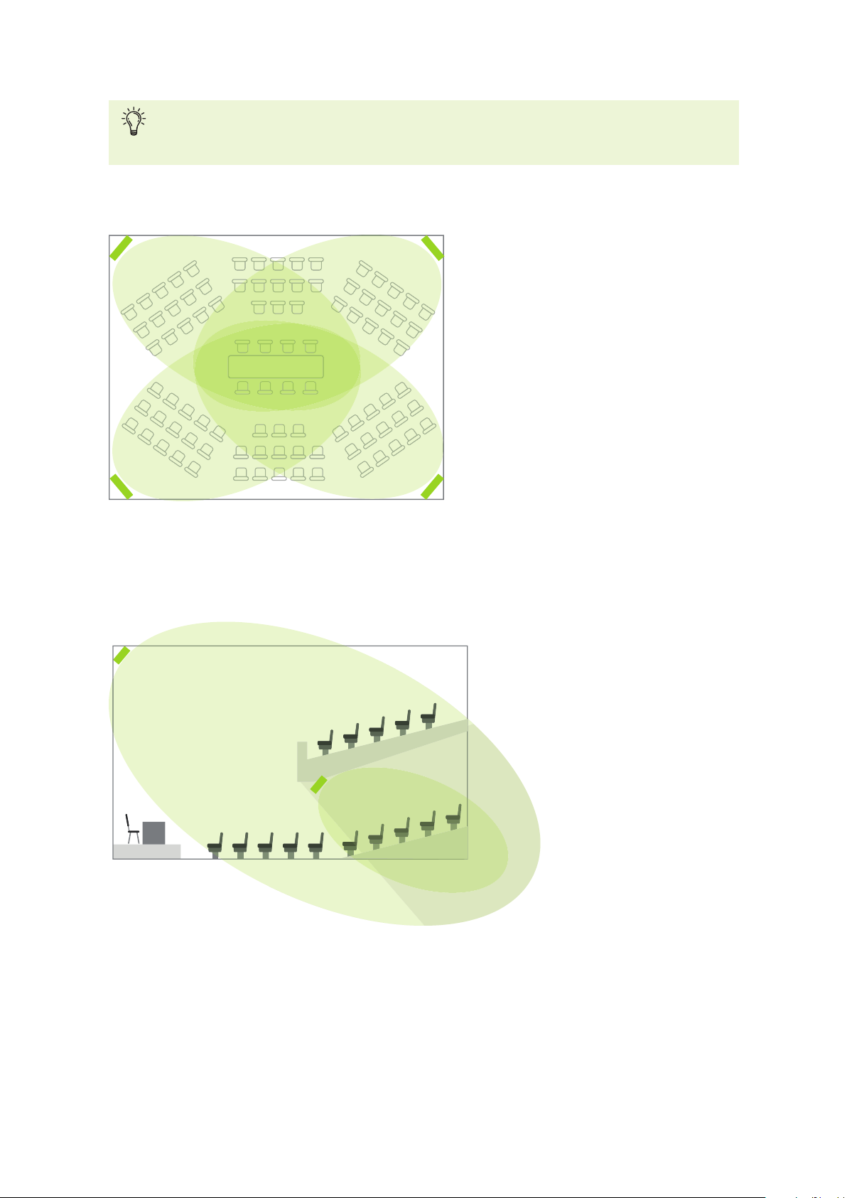
In cases where beam width is an issue, you can position multiple radiators on a cluster. The loop
through the different radiators in the cluster should be done with a short cable (1m).
For rooms where the rearrangement can change or rooms where seats are positioned concentrically,
radiators should be present in every corner of the room.
Figure 1-13 Position of the radiators in a concentrically organized room
In case of rooms with a balcony, an additional radiator needs to be present under the balcony to ensure the
transmission of the signal to the seats under the balcony.
Figure 1-14 Radiator setup for room with a balcony. The balcony blocks all radiation therefore you should place
an additional radiator below the balcony to extend the signal to the people sitting below the balcony.
PO S IT IO N THE L ING UA IR C O MPO NEN TS 39
Page 40
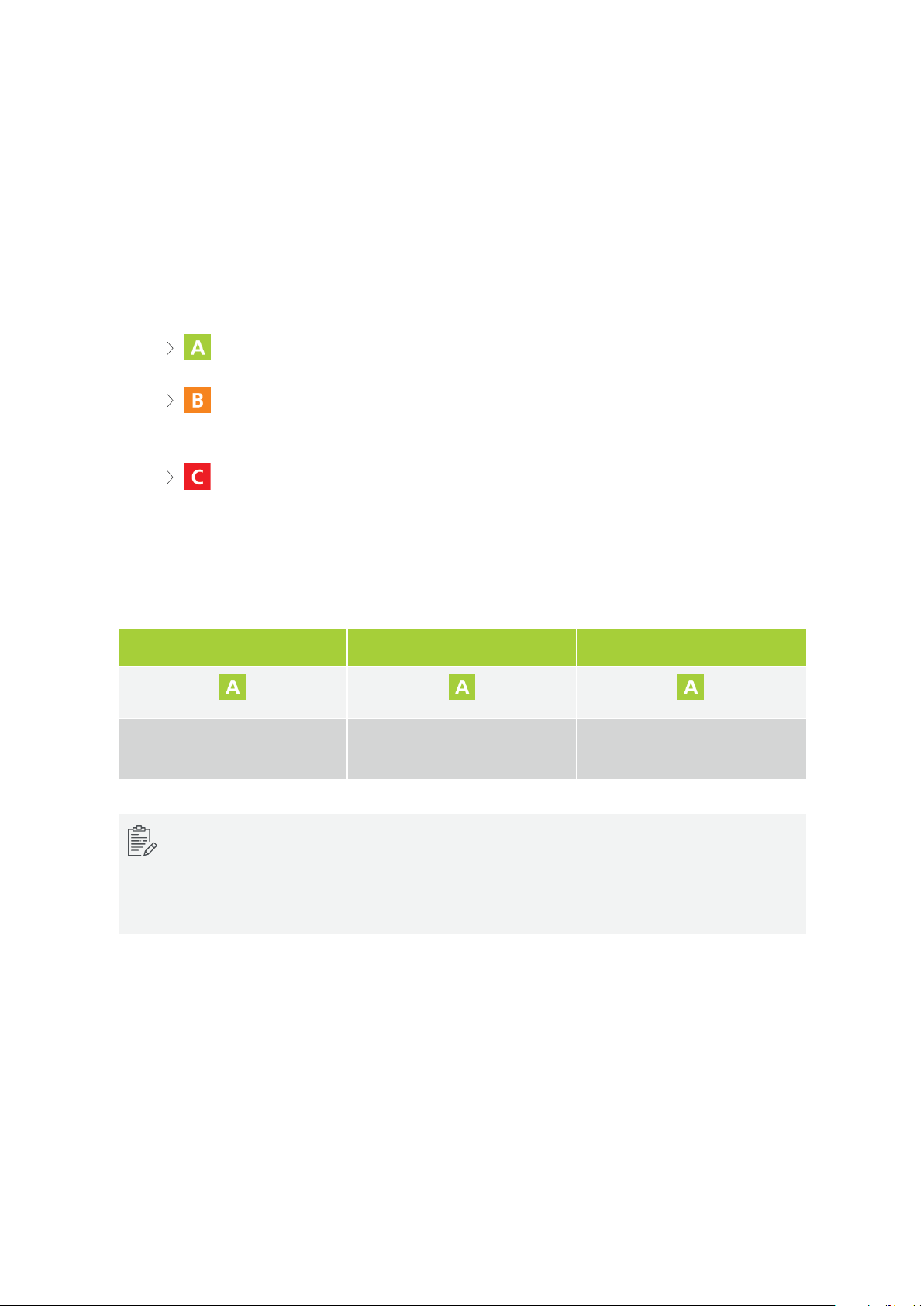
COMPATIBILITY WITH OTHER SYSTEMS
One of the benefits of the Lingua IR system is that you can combine different components of the system
with those of other party systems. The table below shows which functions are compatible with other
systems.
Different icons show how compatible the systems are:
components are compatible and all functionality is maintained
components are compatible, main functionality is maintained, but there are some
limitations
components are not compatible
Compatibility Of Lingua IR Transmitter
RADIATOR
Lingua RAD_H Aladdin RAD Bosch RAD
Automatic delay line compensation No automatic delay line
compensation
Do not mix radiators from different manufacturers on one transmitter. However, when it is
inevitable, you need to keep the following in mind: each radiator from another manufacturer has
different internal delay values. Mixing these radiators may result in bad or even no reception. This
phenomenon especially occurs in regions where the footprints of the radiators overlap.
No automatic delay line
compensation
RECEIVER
The table below shows the compatibility of the Lingua IR transmitter with receivers from different
manufacturers.
CO MPATI BIL ITY WI TH OTHER SY STEMS 4 0
Page 41
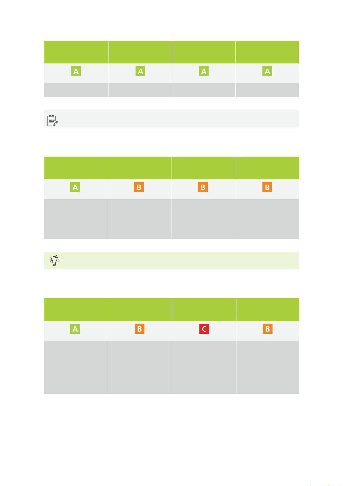
Lingua Rx
Up to 40 channels Maximum 32 channels Maximum 32 channels Maximum 32 channels
Alladin / Taiden Rx
(up to 32 channels)
Taiden Rx
(40 channels)
Bosch Rx
It is possible to mix receiver from different manufacturers in one setup.
Compatibility Of Lingua IR Radiator
Lingua Tx
< Automatic delay line
compensation
Aladdin / Taiden Tx
( up to 32 channels)
< No delay line
compensation: minimize
cable length and use
equal cables lengths
Taiden Tx
( 40 channels)
< No delay line
compensation: minimize
cable length and use
equal cables lengths
Do not mix radiators from different manufacturers.
Compatibility Of Lingua IR Receiver
Lingua Tx
Aladin / Taiden Tx
(up to 32 channels)
Taiden Tx
( 40 channels)
Bosch Tx
< No delay line
compensation: minimize
cable length and use
equal cables lengths
Bosch Tx
< Supports mono
medium quality
< Flexible name
indication from web
server
CO MPATI BIL ITY WI TH OTHER SY STEMS 4 1
< Only supports mono
medium quality (MMQ)
audio
< No channel information
displayed on receivers
Not compatible < Only supports mono
medium quality (MMQ)
audio
Page 42
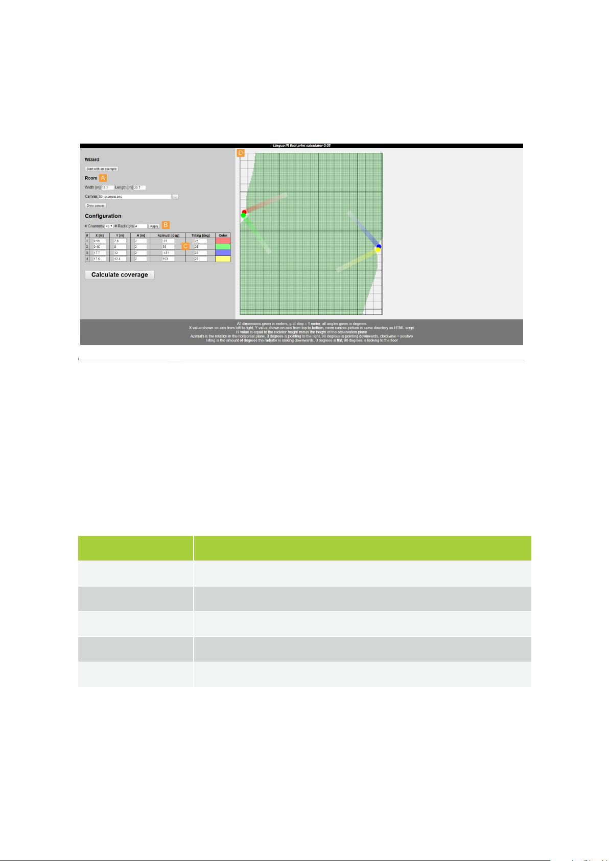
HOW TO USE THE FOOTPRINT CALCULATOR TOOL
Figure 1-15 The footprint calculator tool
With this tool you can visualize the footprint of your radiators by adjusting the position parameters of the
radiators. To get a clear picture of the different footprints in your room, start by defining the length and
width (A) You can also upload an image of your room setup by clicking the button next to the Canvas
parameter, then you can check if all seats have reception. Click Draw canvas to visualize the room.
Select the number of channels (B), because this can significantly affect the footprint of the radiators.Then
add the radiators to the room. Enter the number of radiators and click Apply. Per radiator you can define
the following parameters (C):
Parameter Description
X [m] The X position of the radiator in the room
Y [m] The Y position of the radiator in the room
H [m] The height of the mounted radiator
Azimuth [deg] The radius of the radiator in a horizontal pane
Tilting [deg] The tilting angle of the mounted radiator
HO W TO USE THE FO O T PR INT CALCU L A TO R TO O L 42
Page 43

Each radiator has a different color. If you want to remove radiators, reduce the number of radiators in the
#Radiators field and click Apply. The last radiator(s) in the list will be removed. Click Calculate coverage
to visualize the radiator footprints. When you change one of the parameters, you need to click Calculate
coverage again to update the footprints.
The visualization (D) shows all radiators and the direction of the radiation they emit. In this view you can
also see the combined footprint of all radiators. You can easily add or adjust the radiators to cover your
complete room.
The calculator takes into account the boost mode of the Lingua IR radiator.
HO W TO USE THE FO O T PR INT CALCU L A TO R TO O L 43
Page 44

INSTALLATION PROCESS
This chapter describes how to physically set up and install the Lingua IR system.
Here you can find all technical details needed to correctly install all Lingua IR
components.
Make sure to read the safety instructions before installing the system because the
infrared radiation may cause damage to your eyes.
Page 45
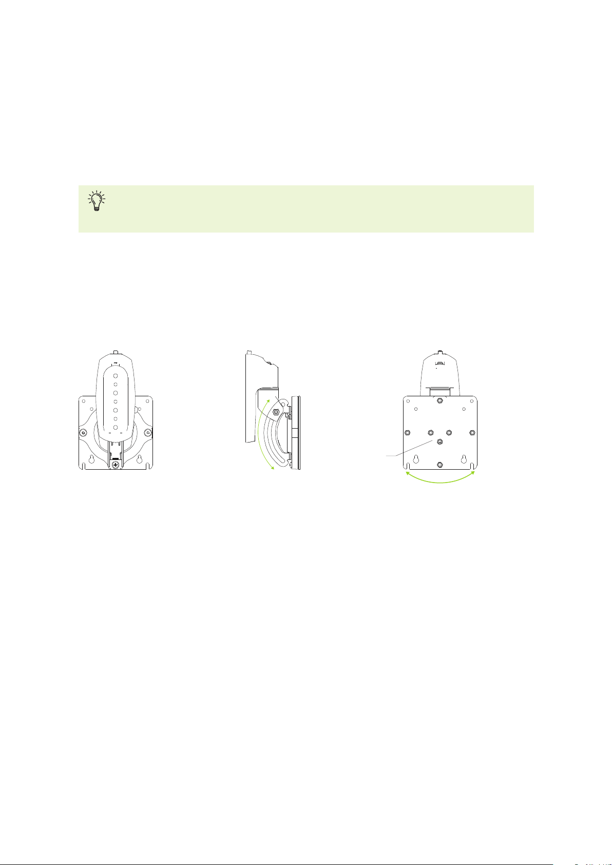
MOUNT THE RADIATORS
Tilt Range
75° down
10° up
Interference Rotation
Range ± 90°
Mounting Pattern
Compatibility
100 × 100
75 × 75
Wall Mounting Side Radiator Mounting SideSide View
The design of the radiators does not restrict you to a to a specific mount. The radiator supports all VESA
100×100 mounts. Below you can find a detailed description of how to install Televic Conference's radiator
mount. For other VESA mounts you can use a similar installation process.
Position the radiator as defined by the calculator tool. After mounting you will still need to test the
coverage of the transmitter using the Lingua IR receivers.
Lingua RAD Mount Specifications
Televic Conference also provides a radiator mount. This is a basic VESA mount which you can tilt and turn
sideways.
Figure 1-16 The front, side, and back view of the Lingua RAD view together with tilting and pivoting range of
the mount
MO U NT THE R A DIA TO RS 45
Page 46
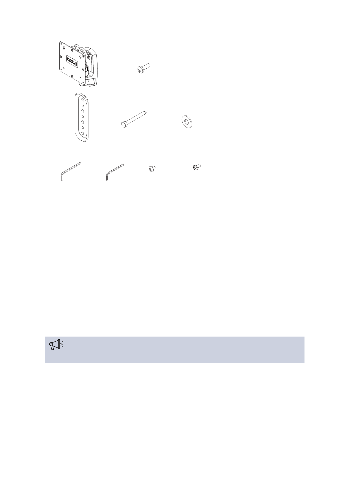
B (4)
M4x14mm
E (1)
[wall bracket]
F (2)
1/4 x 2 1/2”
G (2)
1/4”
3/16”
P (1)
1/8”
Q (1)
A (1)
[monitor arm]
M (1)
#10-32 x 3/8”
N (1)
M4 x 4mm
Figure 1-17 Lingua RAD mount parts
Attach Lingua RAD Mount To The Wall
Follow the procedure described below to attach the RAD mount to a wall:
1. Determine the mounting location on the wall.
2. Use a stud finder to locate 2" x 4" wood stud
3. Use wall bracket (E) to mark and drill two 1/8 x 2 1/2” holes in wall at desired mounting location.
(See Figure 1-18 )
4. Use two 1/4-2 1/2” hex head lag screws (F) and two 1/4” washers (G) to install wall bracket (E) onto
wall.
Over-tightening screws (F) may cause bracket to compress into soft wall surface resulting in
difficult mount installation or improper engaging of set screw in Step 6.
5. Hang monitor arm (A) over wall bracket (E).
6. Secure monitor arm to wall bracket (E) by tightening set screw. Ensure set screw engages back side
of wall bracket (E) to properly secure mount.
MO U NT THE R A DIA TO RS 46
Page 47
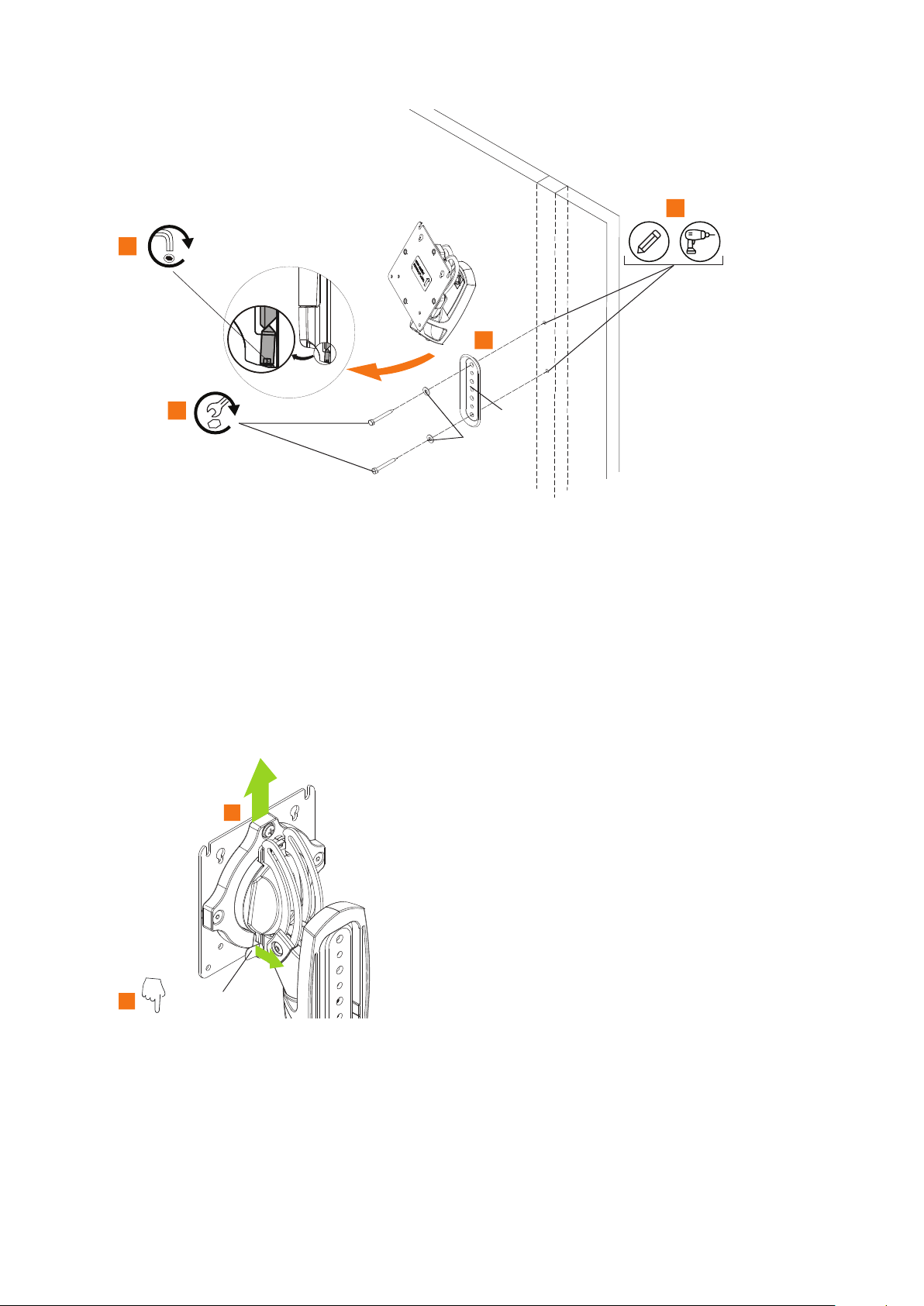
(F) x 2
(E)
(G) x 2
set screw
side view
4
5
3
6
Figure 1-18 How to mount the Lingua RAD mount onto the wall
quick release lever
1
1
Prepare Radiator For Mounting
To attach the radiator to the wall, you first need to remove the faceplate from the mount and attach it to
the radiator. Follow the instructions below to prepare the radiator:
1. Remove quick release faceplate from mount by pulling quick release lever and sliding faceplate off
mount.
MO U NT THE R A DIA TO RS 47
Figure 1-19 How to remove the faceplate from the mount
Page 48
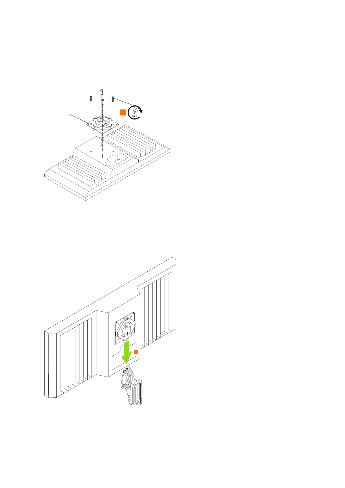
2. Carefully place front face down on protective surface.
(B) x 4
Quick Release
Faceplate
3
3
3. Connect faceplate to back cover. Using a Phillips screwdriver, carefully install four M4x14mm
screws (B) through corresponding holes on faceplate and into the mounting holes on the radiator.
(See Figure 1-20 )
Figure 1-20 Attach faceplate to radiator
4. Position radiator with faceplate attached above mount. (See Figure 1-21 )
5. Slide faceplate onto mounting head until quick release tab clicks into place. (See figure below)
Figure 1-21 Position radiator onto Lingua RAD mount
MO U NT THE R A DIA TO RS 48
Page 49
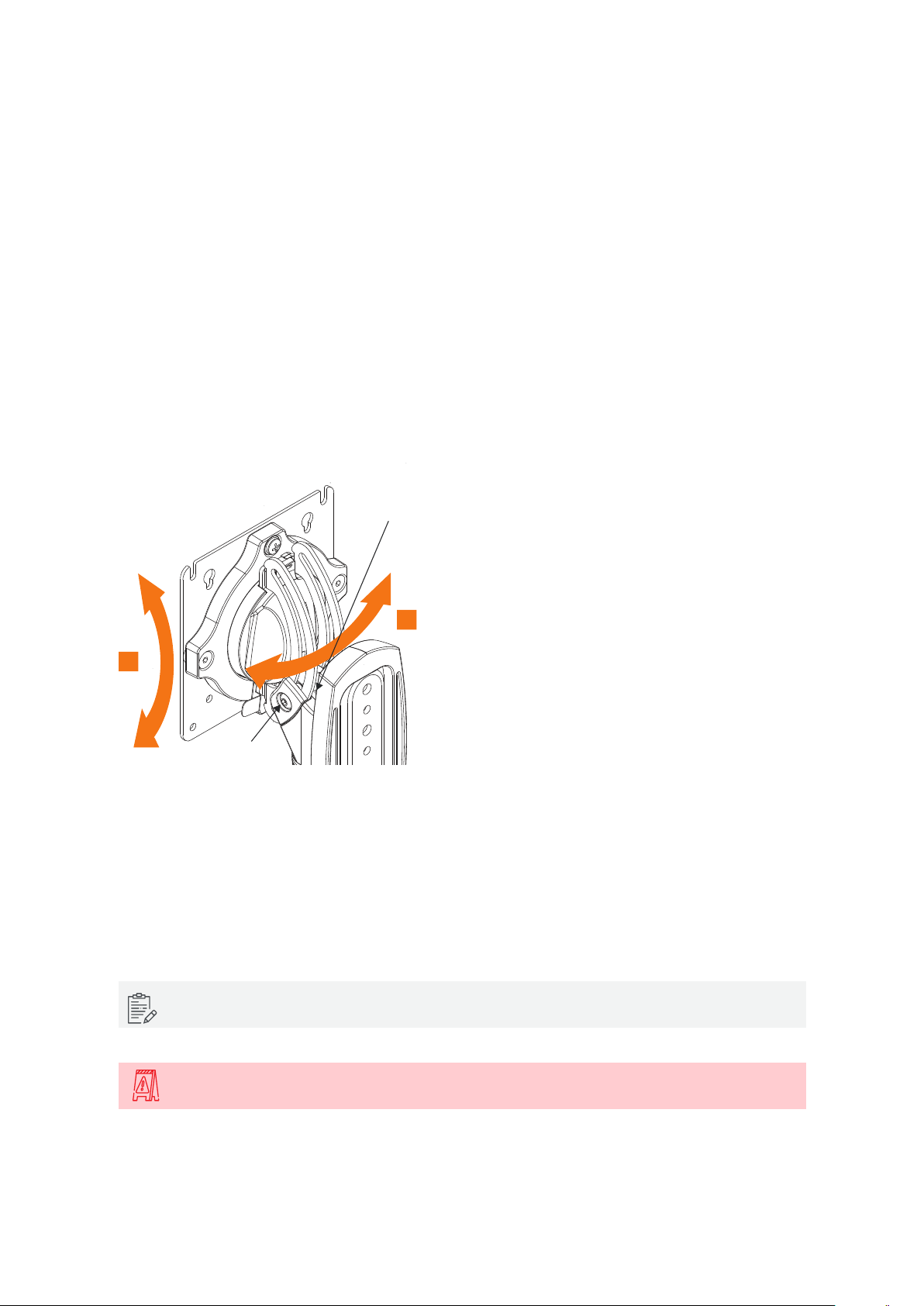
Adjust Orientation Of Mount
Pitch
Pivot Point
Tension
Tension
1
3
PITCH ADJUSTMENT
1. Adjust pitch to desired tilt position. (See Figure 1-22 )
2. Adjust pitch tension screw to change the adjustment tension. (See Figure 1-22 )
PIVOT ADJUSTMENT
3. Adjust pivot position as desired. (See Figure 1-22 )
4. Use 3/16” hex key (Q) to adjust pivot point tension screws to change pivot adjustment tension. (See
Figure 1-22 )
Figure 1-22 How to change the orientation of the Lingua RAD mount
Remove From Mount
Remove the radiator from the mount by pulling the quick release lever and sliding the faceplate off the
mount. (See Figure 1-23 ).
Only remove the radiator from mount when the radiator can be lifted up from the mount!
DO NOT remove radiator unless the radiator is in the upright position!
MO U NT THE R A DIA TO RS 49
Page 50
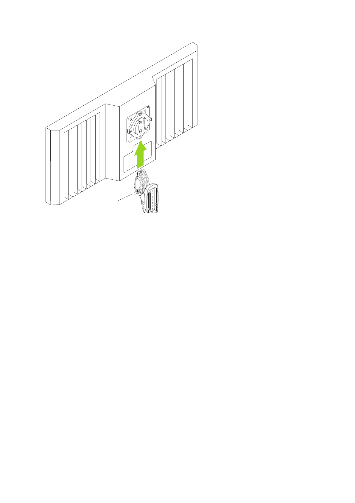
Quick Rel ease Tab
Figure 1-23 How to release the radiator from the RAD mount
MO U NT THE R A DIA TO RS 50
Page 51

COUPLE LINGUA IR COMPONENTS
Introduction
Lingua IR is specifically designed for the wireless language distribution. You need to connect the Lingua IR
system with another system, such as a conference system, to feed the audio channels that needs to be
transmitted. You can connect to different systems, below you can find a description of how to couple the
Lingua IR components and how to connect to an external system.
Couple Transmitter And Radiators
Connect the radiators to the transmitter to send out the infrared signal. One transmitter can feed multiple
radiators. When you couple the radiators to the transmitter, you should keep the following rules in mind:
Only use 75 Ohm coax cables (RG59) with well crimped BNC connectors
You can daisy-chain a maximum of 20 radiators on one port (a total of 80 radiators per
transmitter)
The total cable length per port should not exceed 1 km
You also have the option to use multiple transmitters in one system. To connect the different
transmitters use the LAN connections on the transmitters.
Connect Lingua IR System To A Network
Lingua IR is configured with a web server. Therefore the transmitter and charger needs to be connected to a
network. Use an LAN cable and the LAN connection available on the different computers.
It is possible to daisy chain different charging cases. When using 125V a maximum 3 charging cases can be
daisy chained, when using 230V this amount is 6.
Connect To A Conference System
The Lingua IR system was designed to make it possible to connect to different conference systems to input
audio channels for transmission. Below you can find a detailed description of how to connect the different
conference systems to the Lingua IR transmitter.
CO UPL E LING UA IR C O MPONE NTS 51
Page 52
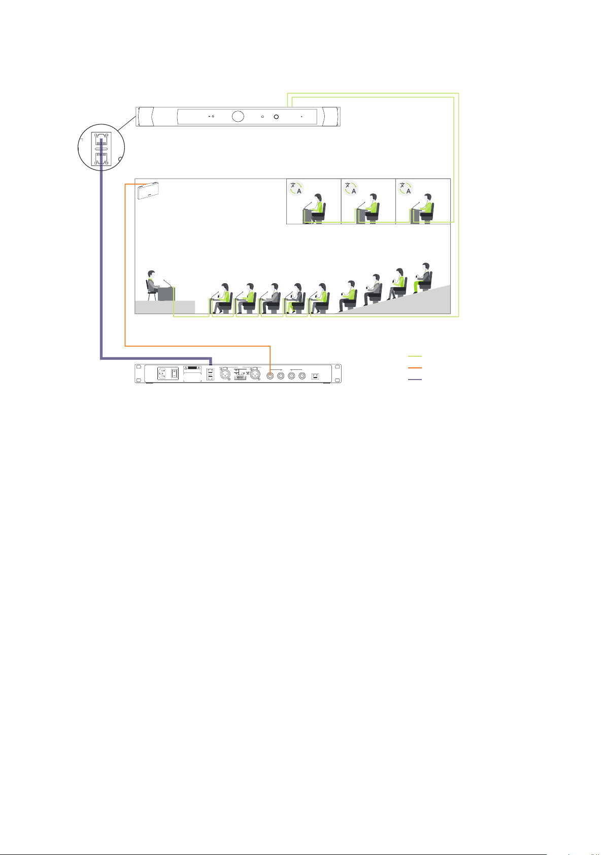
CONNECT TO PLIXUS SYSTEM
televic
REC
DANGER
™
Plixus Engine
Lingua IR Transmitter
Dante
TM
LAN
USB
AUX OUT
AUX IN
Booths with Lingua Interpreter Desk
Plixus
Lingua IR
Dante™
Figure 1-24 How to connect your Plixus conference system with the Lingua IR system to distribute the languages
provided by the interpreters to the participants inside the room. Connection goes through the Dante™
connection on the Plixus engine and the Lingua IR transmitter.
You need to feed input into the Lingua IR system to broadcast this content to the receivers. One option is to
use the audio from your Plixus conference system.
In a typical conference setup some delegates have a microphone and can join the discussion, others are
passive participants that can hear the meeting in the language they prefer. Interpreters provide these
languages with the Lingua Interpreter Desk. Transfer the languages from the Plixus system to the Lingua IR
system over Dante. The radiator can then transmit the infrared signal with these languages to the
receivers in the room.
Use the Dante™ connection on the engine and the transmitter to couple both systems. After connecting
both systems, you still need to configure the Dante™ routing as described in "Set up Dante™" on page57.
CO UPL E LING UA IR C O MPONE NTS 52
Page 53
CONNECT TO CONFERENCE SYSTEM WITH DANTE
DANGER
!"!
™
It is possible to connect with conference system from other manufacturers that provide a Dante™ on their
system. Simply connect the conference system to the Lingua IR transmitter using an LAN cable together
with the Dante™ connections on the devices. Configure the Dante™ routing as described in "Set up
Dante™" on page57
CONNECT TO CONFERENCE SYSTEM WITHOUT DANTE
When you have an analog conference system you can still connect it to the Lingua IR system: for this you
need an analog IN to Dante™ converter. Connect the analog systems to the break-in converter and then
connect Dante™ to the Lingua IR system.
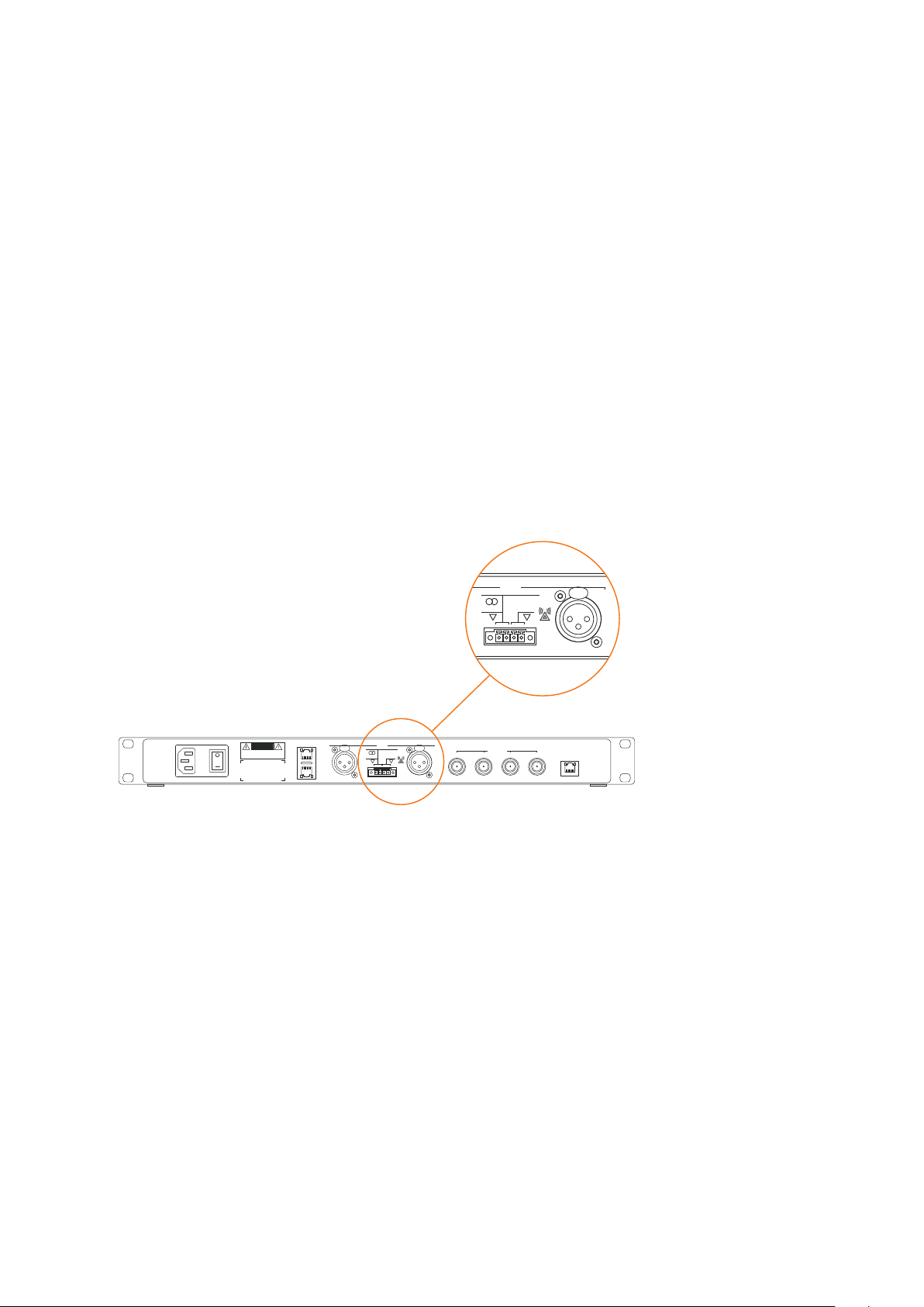
Connect To An Emergency Signal
To connect the transmitter to an emergency signal system, connect a switch (normally open) to the
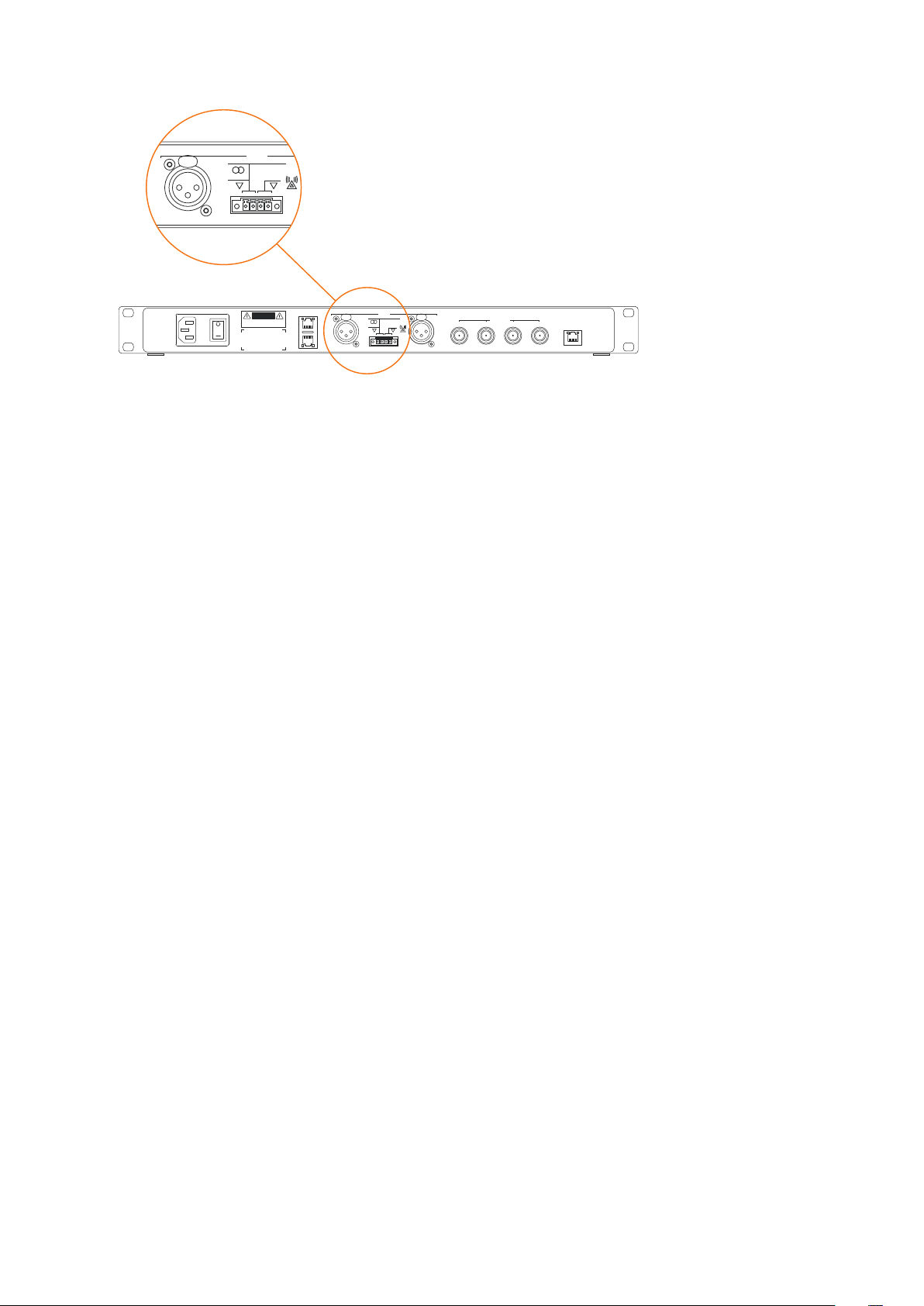
emergency switch connector (AUX Right). When the switch closes then the emergency signal from the AUX
R input will override all other audio input on all channels.
Figure 1-25 Where to connect the emergency signal system
Connect To An Audio Installation
When you want to connect an external audio system to the Lingua IR system to for example play music until
the meeting starts. Connect the audio system to the AUX IN L and make sure to close the left switch of the
connector.
CO UPL E LING UA IR C O MPONE NTS 53
Page 54
DANGER
!"!
!!
"
#
# $ % &$
'
"
()*+,™
'(-!'
!-
"
!!
"
'
"
'(-!'
!-
"
Figure 1-26 Where to connect an external audio system
CO UPL E LING UA IR C O MPONE NTS 54
Page 55
RECEIVER BATTERIES
conference
CAUTION:
DO NOT INCINERATE,
DISASSEMBLE, SHORT,
HEAT ABOVE 60°C/140°F,
USE DESIGNATED
CHARGER ONLY
Li-io n R echa rge able Ba tte ry
1
2
4
Change Receiver Batteries
To change the battery of the receiver follow the procedure described below:
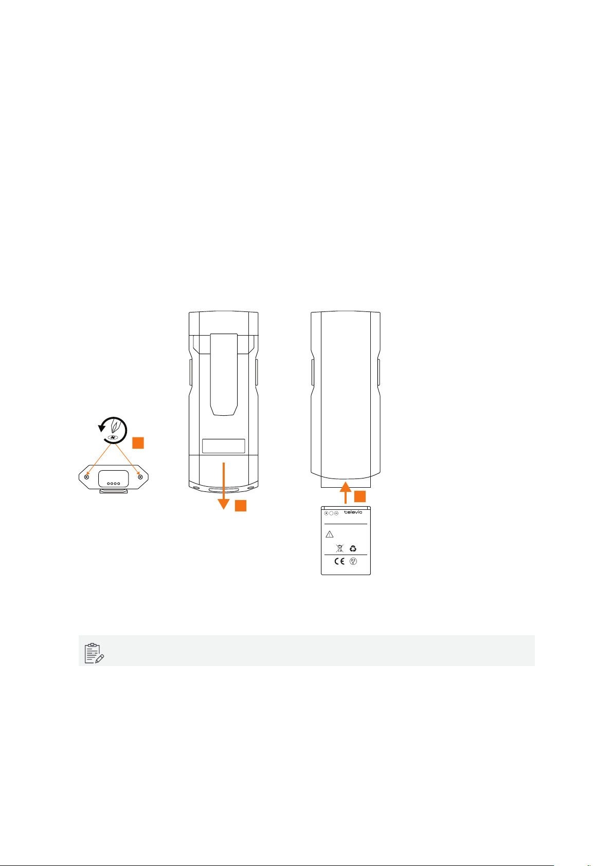
1. Loosen the screws from the bottom of the receiver using a TX6 screwdriver.
2. Remove the bottom part of the receiver.
3. Hold the receiver upright to remove the battery from the receiver.
4. Insert the new battery with the text and the front of the receiver facing the same way.
5. Reattach the bottom of the receiver and tighten the screws.
Figure 1-27 How to change the battery of the Lingua IR receiver
If you insert the batteries incorrect, you will not be able to reattach the bottom of the receiver.
REC EI V ER B A TT ER IES 5 5
Page 56

Battery Maintenance
For low frequency usage: less than four hours and not used daily
Remove the battery after three years.
For high frequency usage: receivers are used over six hours per day and almost daily
Change batteries when the battery life of the receivers is significantly reduced.
REC EI V ER B A TT ER IES 5 6
Page 57
SET UP DANTE™
Netwotk Switch
Central unit
Lingua IR Transmitter Dante™ Controller
televic
REC
Primary Dante™ port
Primary Dante™ port
Prepare The System For Dante™ Configuration
If your setup requires more than 11 languages see the procedure described in "Set up Dante™
routing with more than 11 languages" on page59
If you use the Plixus network with Core functionality, you need to activate the option
Automatically route interpretation channels to Dante in the Plixus Core web server. With
this option all interpretation channels will automatically be assigned to a Dante™ channel.
Note that this option is only available when your setup has 11 languages or less.
When you connect the Lingua IR transmitter to another conference system with Dante™, you need to
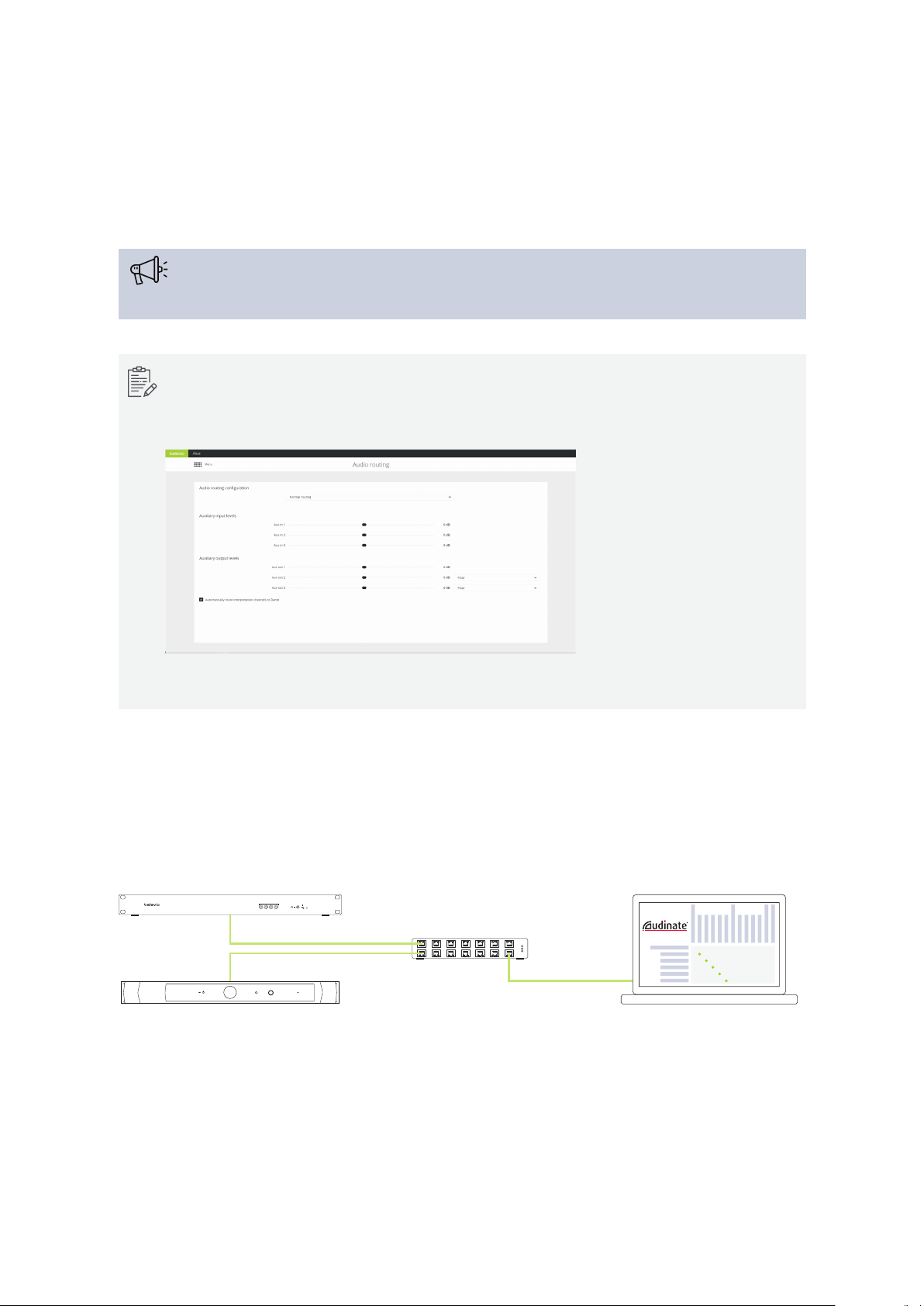
configure some settings before you can use the system. To configure these settings you have to connect all
devices to same network. Use a network switch to connect the central unit of the conference system, the
Lingua IR transmitter and the computer running the Dante™ controller (you can download this from the
Audinate website).
Figure 1-28 All Dante™ devices need to be connected before you can configure the Dante™ routing
SE T U P D ANTE™ 57
Page 58
Make sure your computer does not have a fixed IP address. A Dante-enabled device
connected to a network will automatically setup its own network configuration, including its IP
address.
If the network has a DHCP server, which may be the case for installed networks, it will receive its
IP configuration using the standard DHCP protocol.
On a network without a DHCP server, which may be the case for temporary or smaller networks,
the Dante-enabled device will automatically assign itself an address using link local protocols, in
the same way PCs and printers often do.
Configure Dante™ Routing
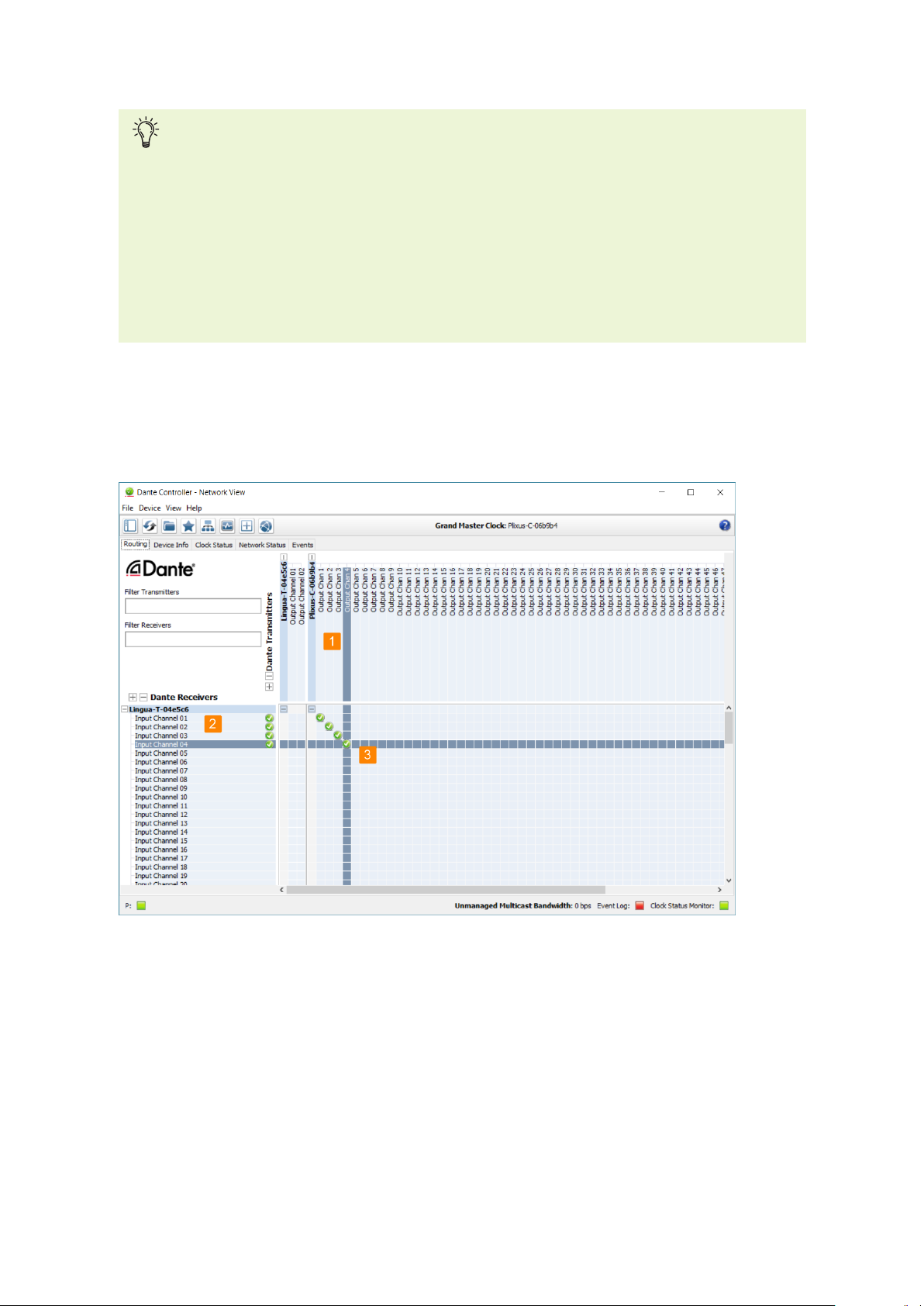
Once the Dante™ devices are connected, you need to route the Dante™ channels from your input system
to the Dante™ channels of the transmitter.
Figure 1-29 How to route the output from the conference system to the input of the Lingua IR transmitter
The Routing tab of the controller shows all Dante™ devices with their inputs and outputs. The top part
shows the outputs. Here you can find the output from your conference system (1). The bottom part on
the left hold all inputs together with the Dante channels of the transmitter (40 channels) (2).
SE T U P D ANTE™ 58
Page 59
Now link the output of the conference system to the input channels of the transmitter using the
matrix (3). Do this by checking the box where the input and output intersect. A checkmark appears when
the routing was successful.
Once you finish the configuration of the routing, this configuration is remembered on every Dante™ device.
Therefore you can remove the network switch and connect the transmitter to the central engine directly.
Set Up Dante™ Routing With More Than 11 Languages
In Plixus Core it is only possible to configure up to 11 languages. If your setup requires more than 11
languages you need CoCon Interpretation and CoCon Audio Routing to configure the languages that
will be available on the Dante™ channels. Use CoCon Interpretation to set up your languages and
booths.
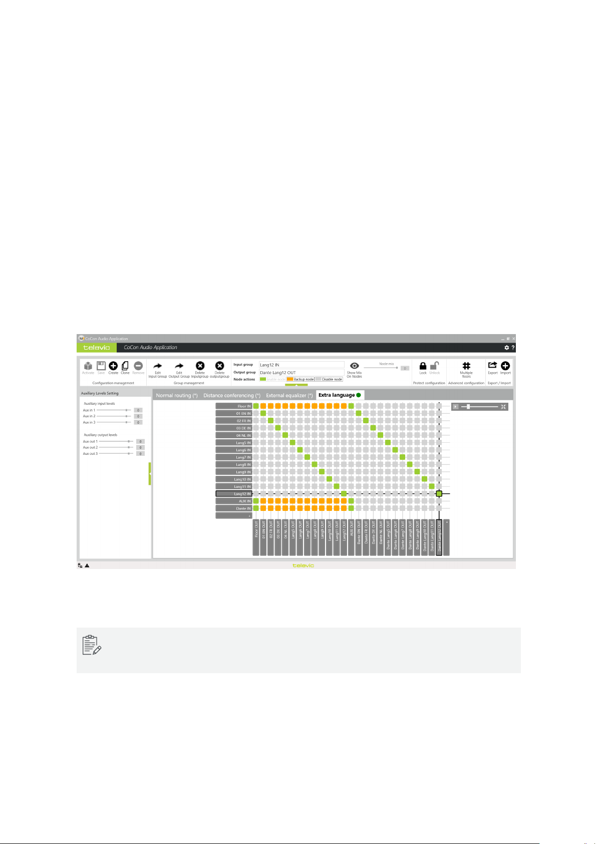
In CoCon Audio Routing you can configure which input language to route to which output channel of the
microphone unit. Every input language you then also need to route to a Dante™ output channel, these will
then be available on the receivers.
Figure 1-30 How to route the audio input to the Dante™ output channels in CoCon Audio Routing
For more information on the CoCon Interpretation and CoCon Audio Routing applications see the
CoCon Core user guide.
SE T U P D ANTE™ 59
Page 60

TEST RADIATOR COVERAGE
Best Practices For Good Infrared Signal Reception
There should be no objects between the receiver and the transmitter.
Do not attach any kind of object, such as the headphone cord or a sticker, on the top of the
receiver where the infrared sensitive diode is located.
Test The Coverage Area
After installation you need to test the coverage of the transmitter in the room itself.
1. Configure the channels as described here .
2.
Activate the test tone on the transmitter using the web server ( see ).
3. Plug in headphones to activate the receiver.
4. Test the reception quality in all positions and directions. Go around the room and test all positions
that should receive the infrared signal using the test tone.
Causes For Bad Infrared Reception
RADIATOR TRANSMISSION
One option for the lack of reception is that you are testing an area that is not covered by the footprint of the
radiator. Another reason is the presence of objects between the radiator and the receiver that block the
infrared radiation. This could be structural elements such as balcony, poles or beams.
BLACK SPOTS
When the infrared system has multiple radiators which use different cable lengths, the signal will reach the
radiators at different times. As a consequence the radiation from the different radiators can cancel each
other out. Solve this by using the automatic delay line compensation (). It is possible that you may need
to tune these settings a little inside the room.
Typically you can identify a black spot as an area of bad reception that only occurs along a specific line
and/or rotating the receiver into another direction will restore the reception. Confirm this type of
interference by turning of one of the radiators. Typically higher bands are more sensitive to black spots.
IR radiation that is reflected by highly reflective surfaces can also cause black spots.
TE ST RA DIATO R CO V E RAG E 60
Page 61

INTERFERENCE
Other systems using infrared at certain frequencies can disturb the reception of the receivers. Disable
the bands that can experience interference using the web server. See for more information.
TE ST RA DIATO R CO V E RAG E 61
Page 62

CONFIGURATION
This chapter describes how to configure the Lingua IR system using the Lingua IR
web server.
Page 63
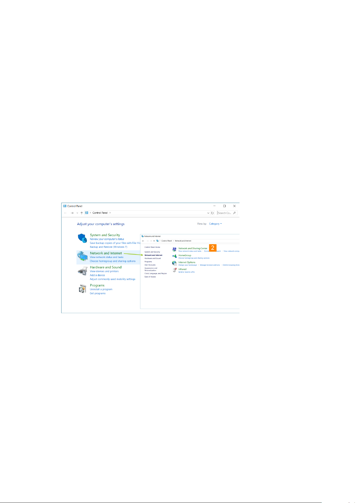
CONFIGURE IP SETTINGS
Before you start using the Lingua IR web server you need to configure your local IP settings to be able to
access the web server. Follow the procedure below to configure this.
To be able to access the web server your computer needs an IP address and subnet mask that can access
the IP address of the engine. The default IP address of the transmitter is 192.168.0.140 and of charging
case 192.168.0.150, which means the computer should have an IP address that is within the same subnet,
like 192.168.0.200. The subnet mask must be the same for all equipment on the network, being
255.255.255.0.
Change IP Settings In Windows
1.
Go to Control panel.
2.
Click Network and Internet and then Network and sharing center.
CO NF IG U R E I P S ETTINGS 63
Page 64
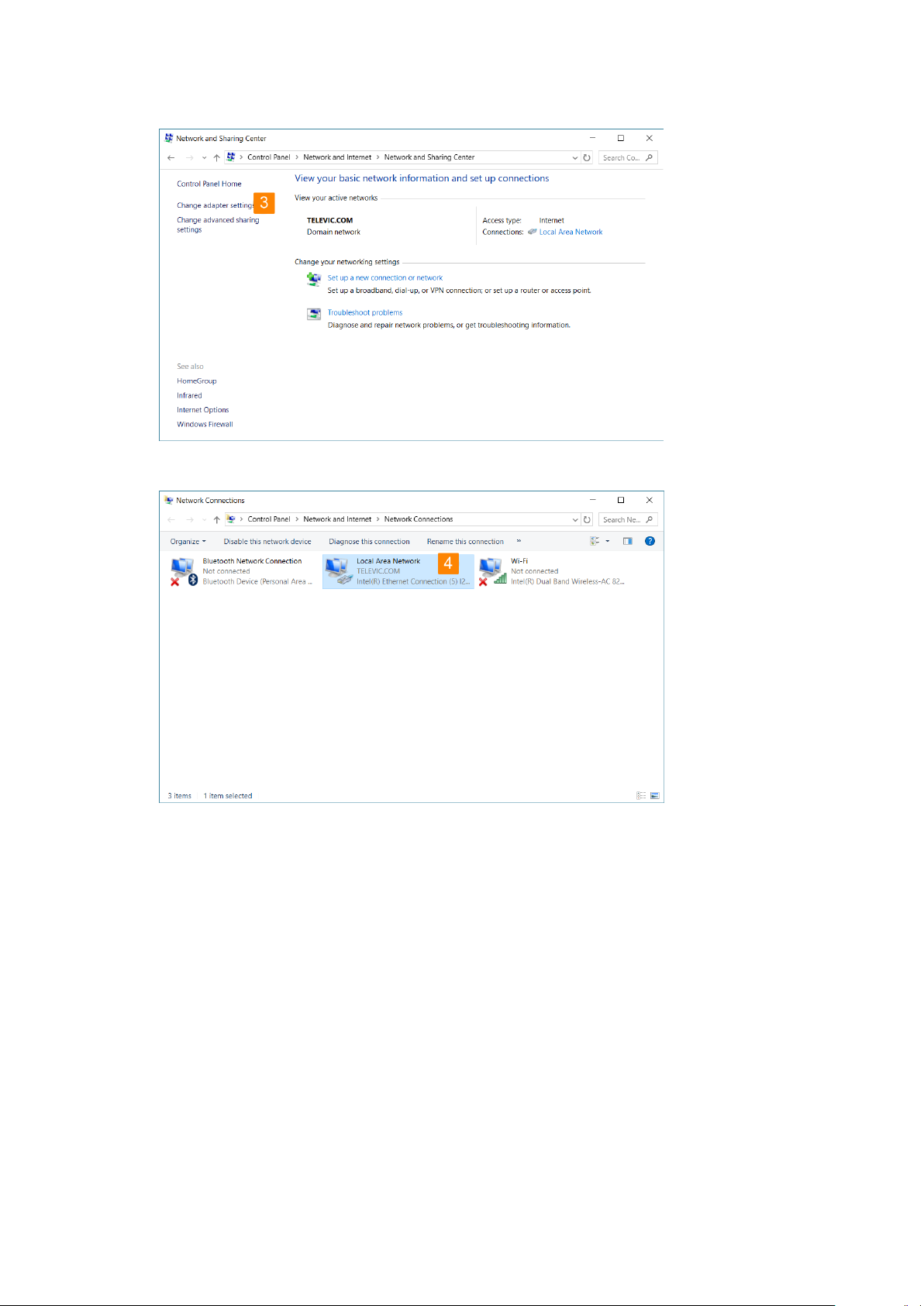
3.
Click Change adapter settings in the menu on the left.
4.
Right-click the Local Area Connection and select Properties.
CO NF IG U R E I P S ETTINGS 64
Page 65
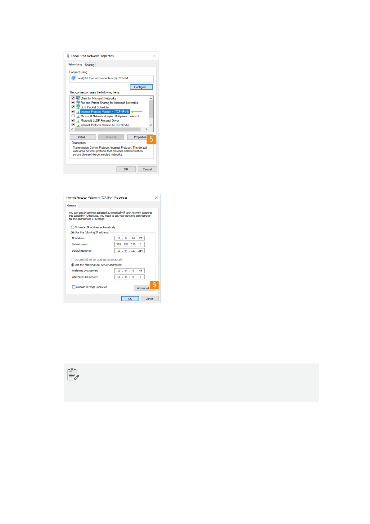
5.
Select Internet Protocol Version 4 (TCP/IPv4) and click Properties.
6.
To assign a fixed IP address to your computer, click Advanced.
7.
Click Add in the IP address pane.
8. Enter an IP address in the range of the transmitter and charging case, for example 192.168.0.26. Fill
in 255.255.255.0 as subnet mask.
When you use mulyiple networks on your computer (for example when your computer is
connected to the Internet via WIFI, and it is connected to a central engine using a network
cable), do not fill in the default gateway.
9.
Click OK. You are now ready to access the Lingua IR system.
CO NF IG U R E I P S ETTINGS 65
Page 66
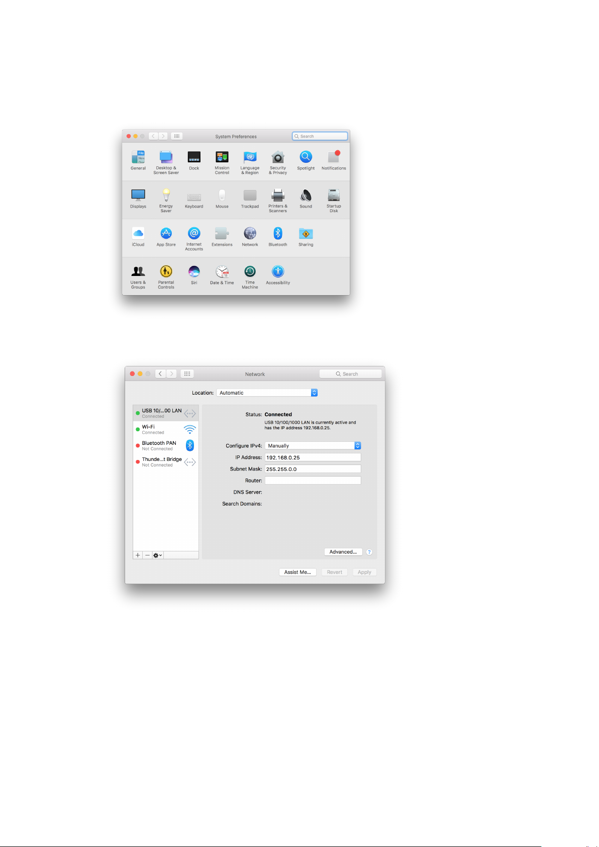
Change IP Settings In MacOS
1.
Go to the Apple Menu and select System Preferences.
2.
Select Network from the menu.
CO NF IG U R E I P S ETTINGS 66
Page 67
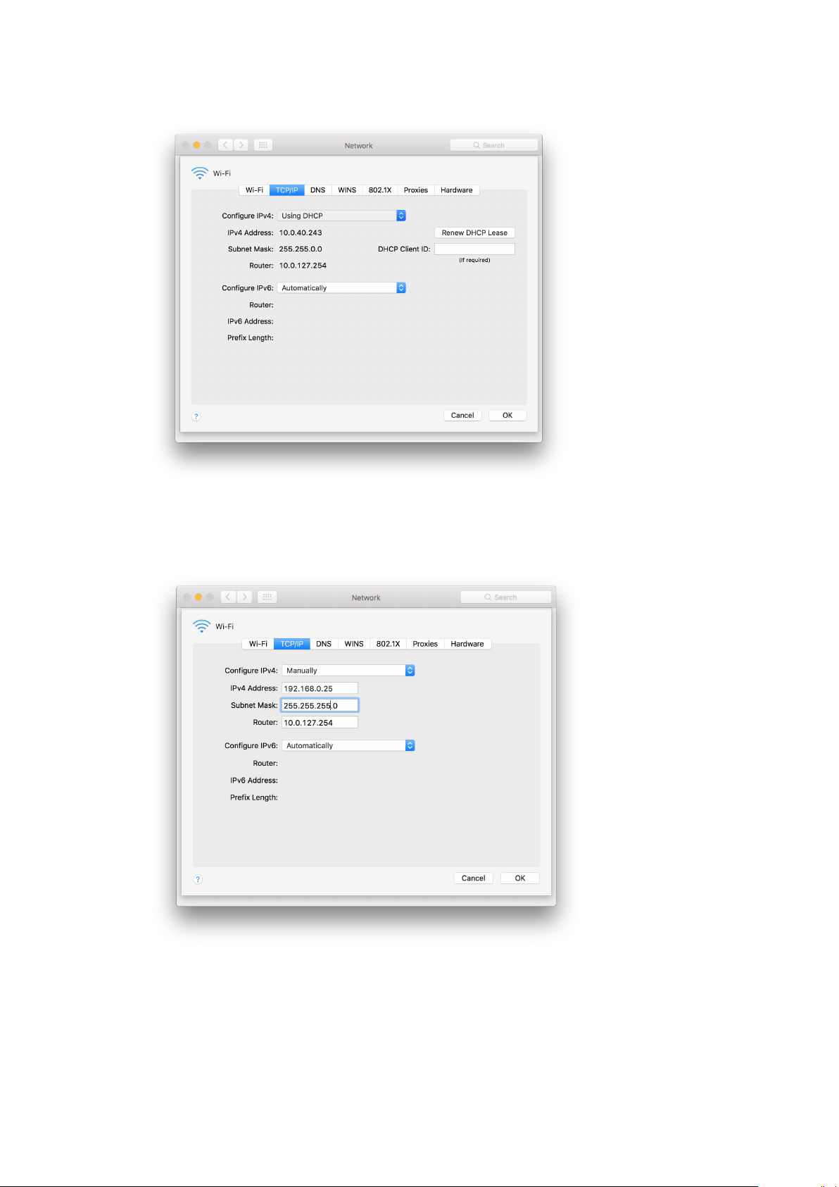
3.
Click the Advanced button.
4.
Select TCP/IP in the menu on top.
5.
Change Configure IPv4 to Manually.
CO NF IG U R E I P S ETTINGS 67
Page 68

6. Enter an IP address in the range of the engine, for example 192.168.0.25. Fill in 255.255.255.0 as
subnet mask.
7.
Click OK.
CO NF IG U R E I P S ETTINGS 68
Page 69
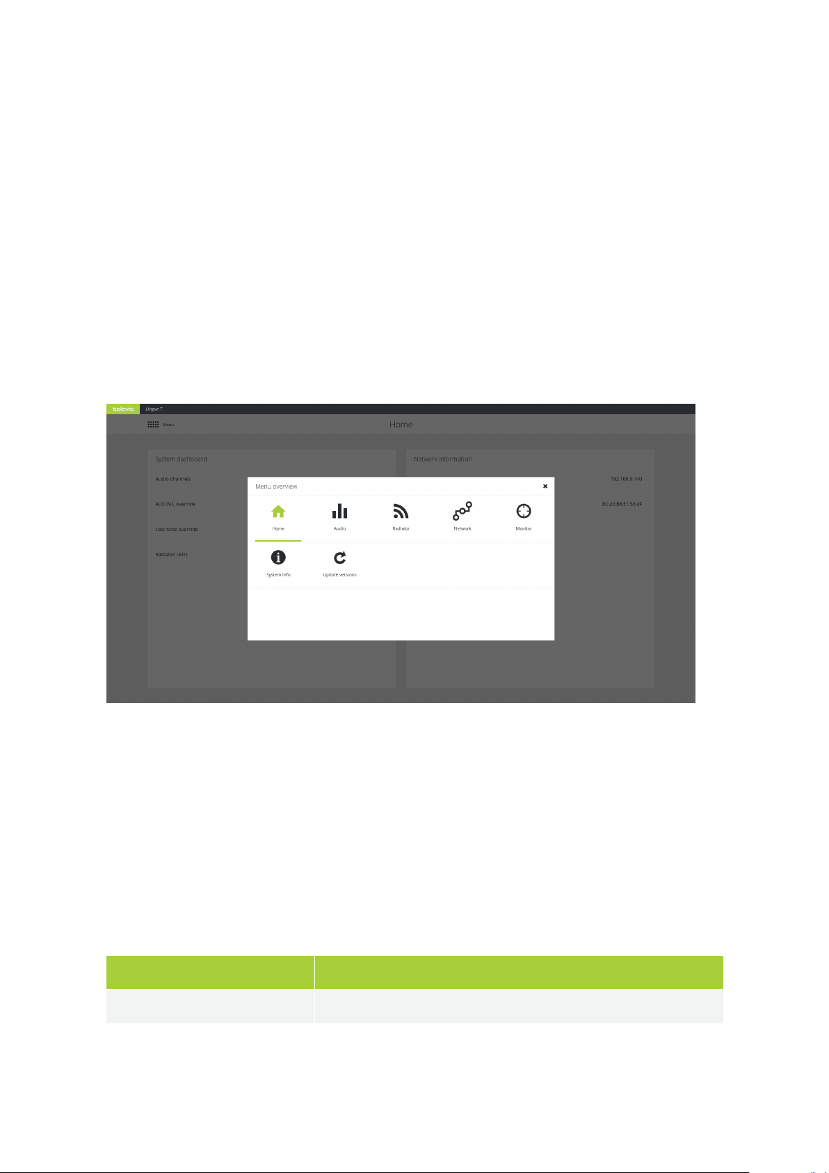
CONFIGURE THE TRANSMITTER SETTINGS
Introduction
Lingua IR has an intuitive web server that allows you to configure different transmitter and radiator settings.
With the web server you can configure the audio settings, the radiator, the network settings, some
monitoring settings, licensing and updates.
The default IP address of the transmitter web server is 192.168.0.140. To be able to access the web server,
configure your network settings as described in "Configure IP settings" on page63.
Figure 3-1 The main menu of the Lingua IR transmitter web server
The Home Screen
The Home screen is the landing page of the transmitter. This page shows a summary of the most important
parameters, some of which you can adjust here or click the parameter to go to the page where you can
configure them. Two group of settings are available: the System dashboard settings and the Network
information settings.
The following system dashboard settings are displayed:
Setting Description
Audio channels The amount of configured channels
CO NF IG U R E T HE TRAN SM IT TE R S ET TI NGS 69
Page 70
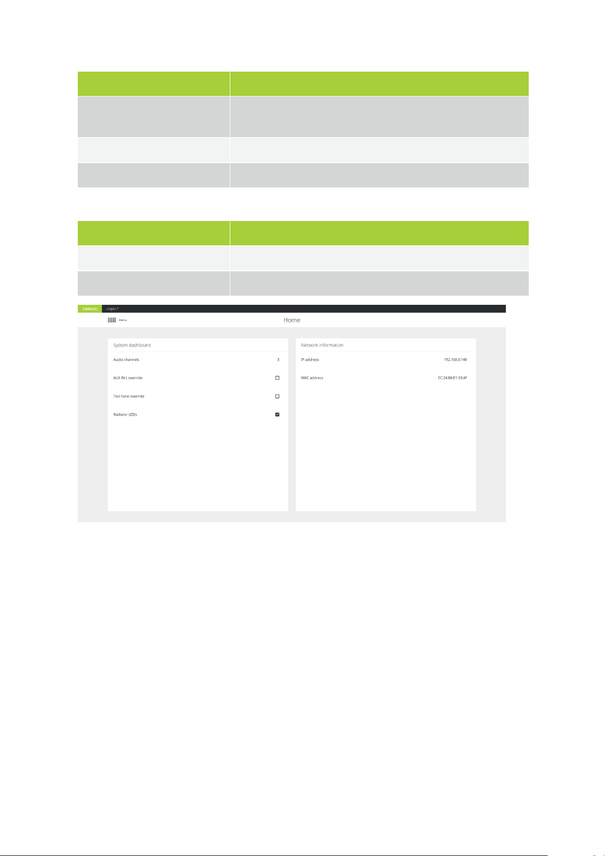
Setting Description
AUX IN L override Select to override the audio on all channels with the audio from the AUX
IN L input.
Test tone override Select to override the audio on all channels wit a test tone
Radiator LEDs Switch the radiator status LEDs on or off
The following network information is displayed:
Setting Description
IP address The IP address of the transmitter
MAC address The MAC address of the computer you use to access the web server
Figure 3-2 The transmitter Home page
CO NF IG U R E T HE TRAN SM IT TE R S ET TI NGS 70
Page 71
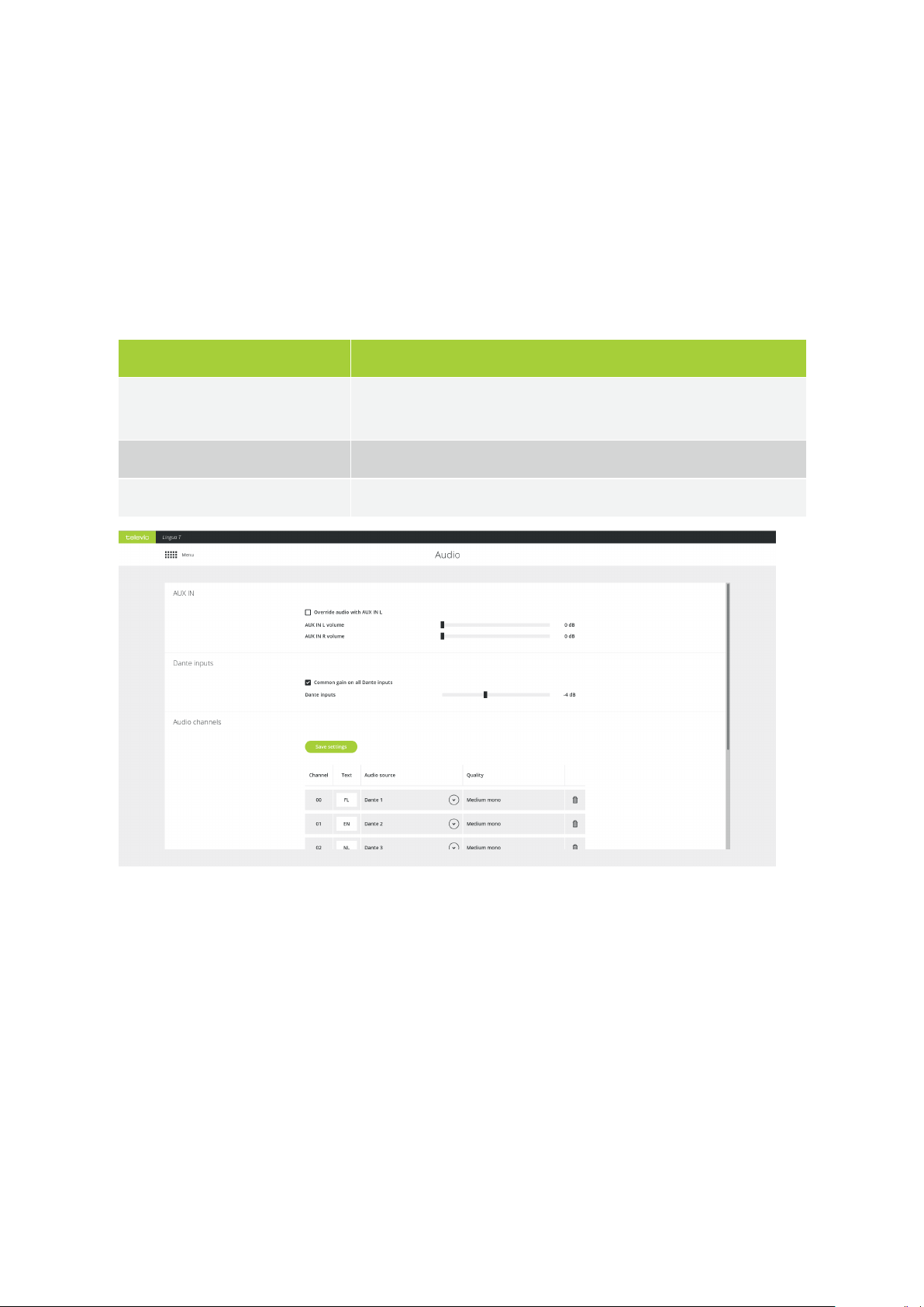
CONFIGURE TRANSMITTER AUDIO SETTINGS
Set AUX IN Settings
With the AUX IN settings you can configure the following parameters
Parameter Description
Override audio with AUX IN L When you select this option, the AUX IN L audio will replace the audio
on all output channels
AUX IN L volume Set the volume of the AUX IN L audio
AUX IN R volume Set the volume of the AUX IN R audio
Figure 4-1 Transmitter audio settings (part one)
Configure Dante Input Gain Settings
The Dante inputs section allows you to set the gain of all Dante inputs at once or change the gain of the
individual Dante channels. Select Common gain on all Dante inputs to use the same gain settings for
all channels.
CO NF IG U R E T RAN SMITTER AUDI O SET TI NGS 71
Page 72
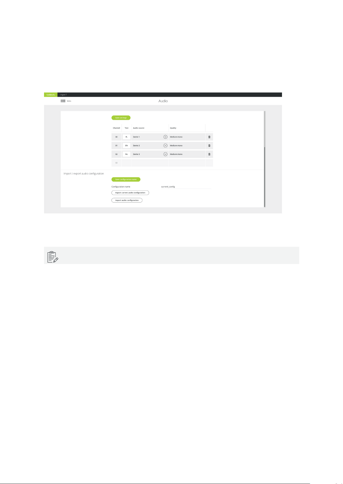
Configure Audio Channels
In the Audio channels section you can add or remove audio channels. Per channel you can set the text to
be displayed on the receiver as well as which Dante™ channel is routed on that channel. Click Save
settings to confirm the configuration.
Figure 4-2 Transmitter audio settings (part two)
Beware that you cannot add more channels than specified in your license.
Import / Export Audio Configuration
It is possible to import and export audio configuration settings. Define the Configuration name and click
Save configuration name to confirm. Click Export current audio configuration to export the settings
or Import audio configuration to import settings.
CO NF IG U R E T RAN SMITTER AUDI O SET TI NGS 72
Page 73
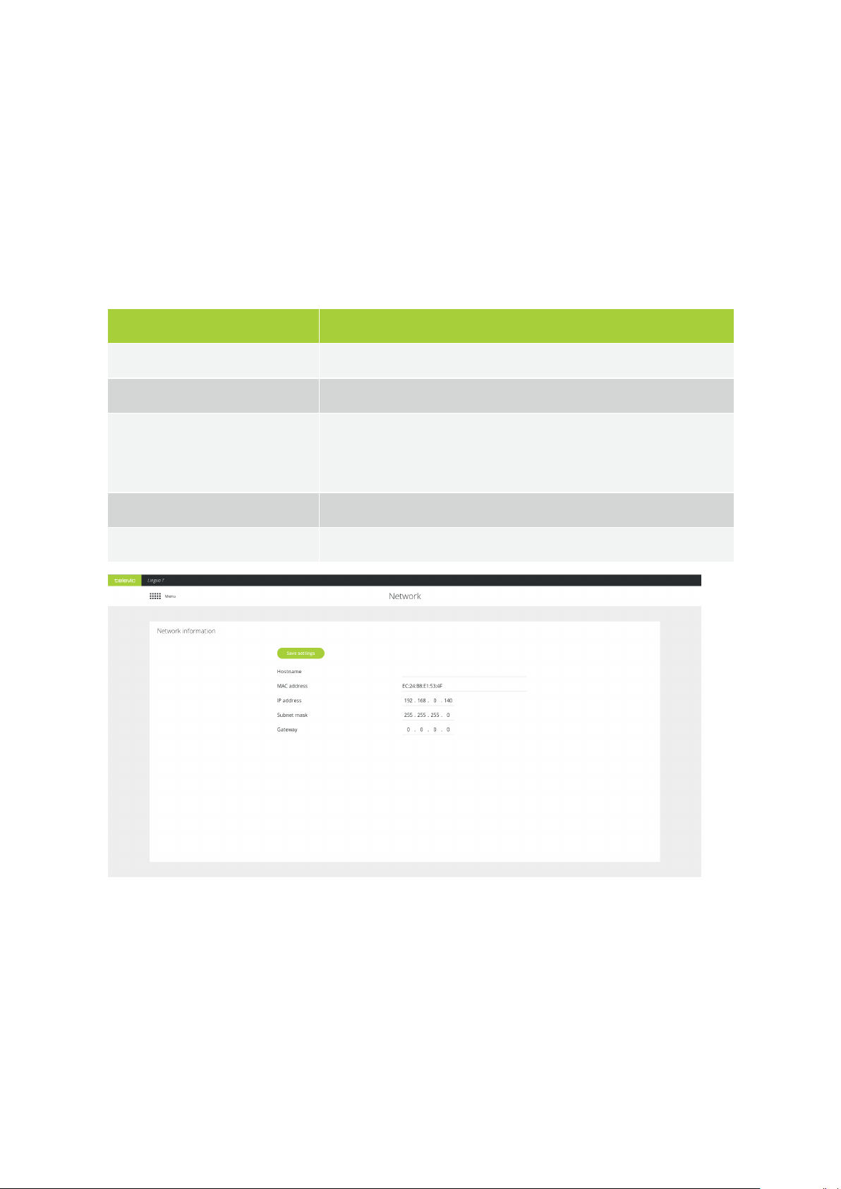
CONFIGURE TRANSMITTER NETWORK SETTINGS
Network Information
On the Network page you can configure the following parameters:
Parameter Description
Hostname The name you want to give to the Lingua IR system
MAC address The MAC address of the transmitter
IP address The IP address to access the transmitter, the default value is
192.168.0.140
page automatically reloads using the new IP address.
Subnet mask Default subnet is 255.255.255.0
Gateway The access point to another network.
. When you change the IP address of the transmitter, the
Figure 5-1 Network information page
CO NF IG U R E T RAN SMITTER NETW O RK S ETTINGS 73
Page 74

Page 75
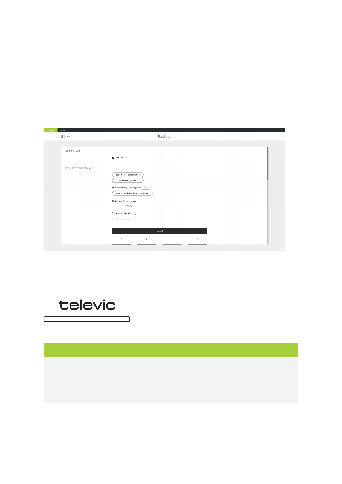
CONFIGURE RADIATOR SETTINGS
1 2 3
Radiator Functionality
On the transmitter web server you can configure different radiator settings. You can only access and
configure the radiator through the transmitter. On the radiator page you can choose to disable the radiator
status LEDs. In order not to distract, the status LEDs of the radiators can be switched during a meeting.
Figure 6-1 The Radiator page
You can also select the information the LEDs display. This is convenient when setting up the system. To
change the LED indication mode click Open initialization. The following options are available:
Radiator LED mode Description
Normal mode
When initialization is open the LED light will be blue indicating
initialization.
Normal mode use the LEDs as described in "Lingua Radiator" on
page1.
CO NF IG U R E R A DIA TO R SETTIN G S 75
Page 76
Radiator LED mode Description
Radiator 2
Radiator 1
No signal
1
2
Radiator identification
Delay line compensation value
Power level
Current radiator temperature
Shows the position of the radiator.
LED 1 shows the port number of the transmitter.
LED 2 and 3 show the position of the radiator on that branch.
LED 2 shows multiples of ten and LED 3 shows the number
zero to nine.
LED 2 and 3 show the delay line compensation value of the radiator.
LED 2 shows multiples of ten and LED 3 shows the number zero to
nine.
LED 3 shows the power level of the radiator. Zero means power off, one
is reduced power, two is normal power and three is boost power. For
more information on power levels see "Lingua Radiator" on page1.
LED 2 and 3 show the current temperature of the radiator.
LED 2 shows multiples of ten and LED 3 shows the number zero to
nine.
Delay Line Compensation
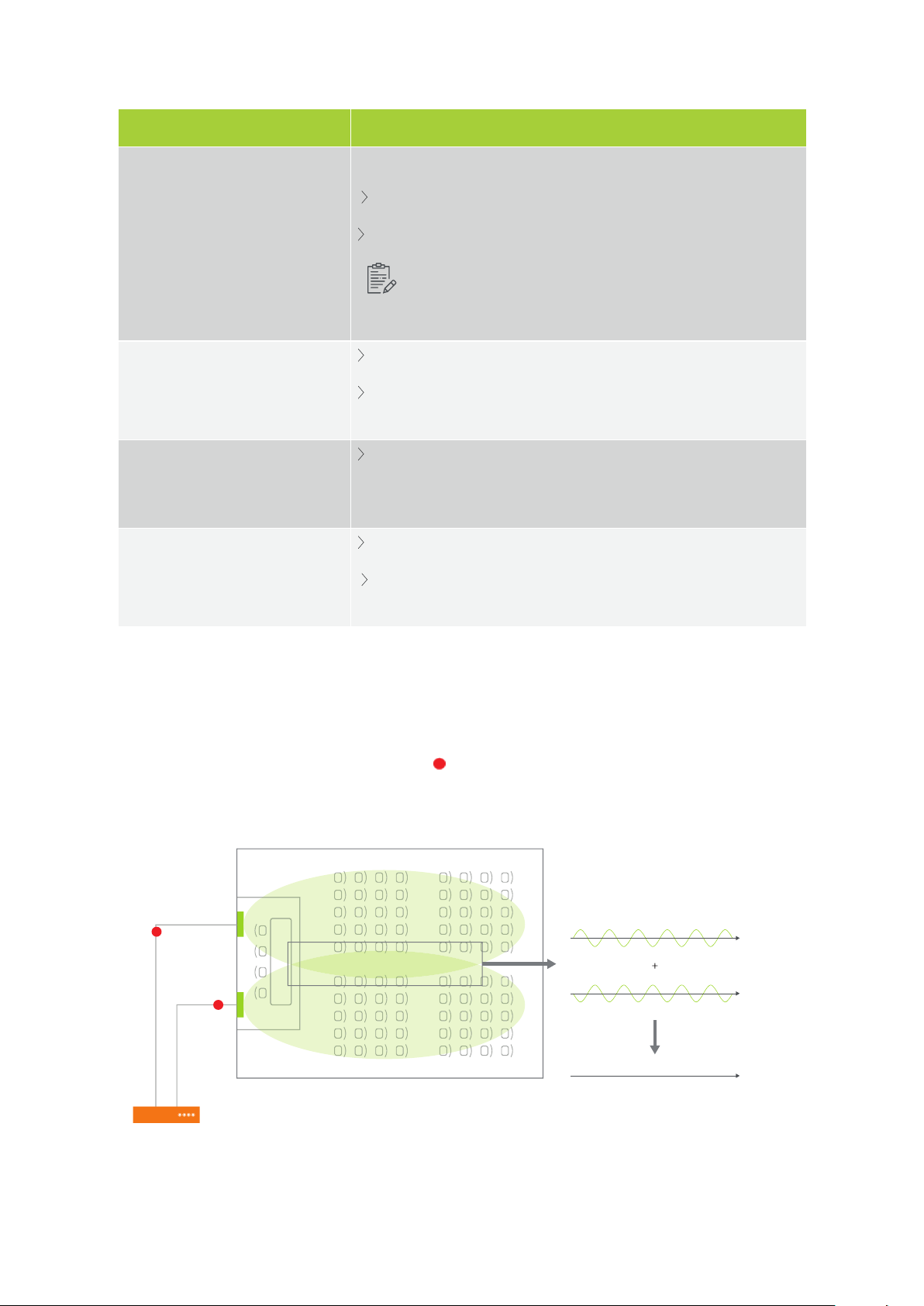
When two or more radiators have overlapping footprints then the signal of these radiators can cancel each
other out in the overlapping areas. This is the case when the length of the cable differs between the
different radiators, due to the delay of the signal ( ) over the cable. This can lead to black spots, where
you are unable to receive the infrared signal of the radiators using the receivers.
CO NF IG U R E R A DIA TO R SETTIN G S 76
Page 77
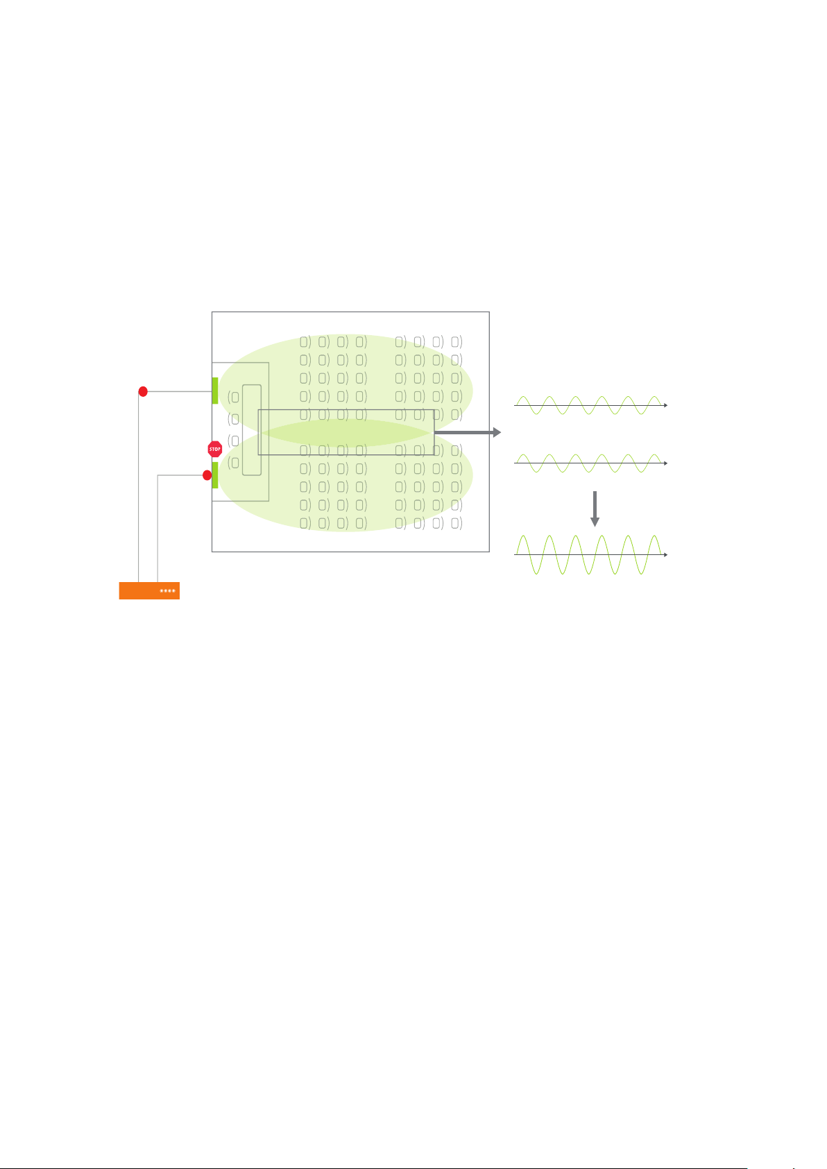
Figure 6-2 The relation between the delay of a signal in the cable and the signal picked up by the receiver. When
+
Radiator 2
Radiator 1
Enhanced
Signal
1
2
the infrared signals of the radiators are asynchronous, they cancel each other out. As a result the receiver will
have no audio.
To prevent this effect you need to compensate for this delay. This means that the radiators need to send
their signal at the same time of that of the slowest radiator, delaying their signal until the slowest radiator
receives the data. The slowest radiator is the one which has the longest cable between the transmitter and
the radiator.
Figure 6-3 After delay line compensation the radiator halts the transmission of its infrared signal until the
slowest radiator also receives the signal.
The Lingua IR system has an automatic delay line compensation mechanism where the software measures
the delay based on pulses it sends over the cable. Based on the results it will specify the delay as a multiple
of 25ns (for 71.98.0223) or 12,5 ns (71.98.0220). The web server will also give a visual representation of all
radiators and their distance to the transmitter.
CO NF IG U R E R A DIA TO R SETTIN G S 77
Page 78
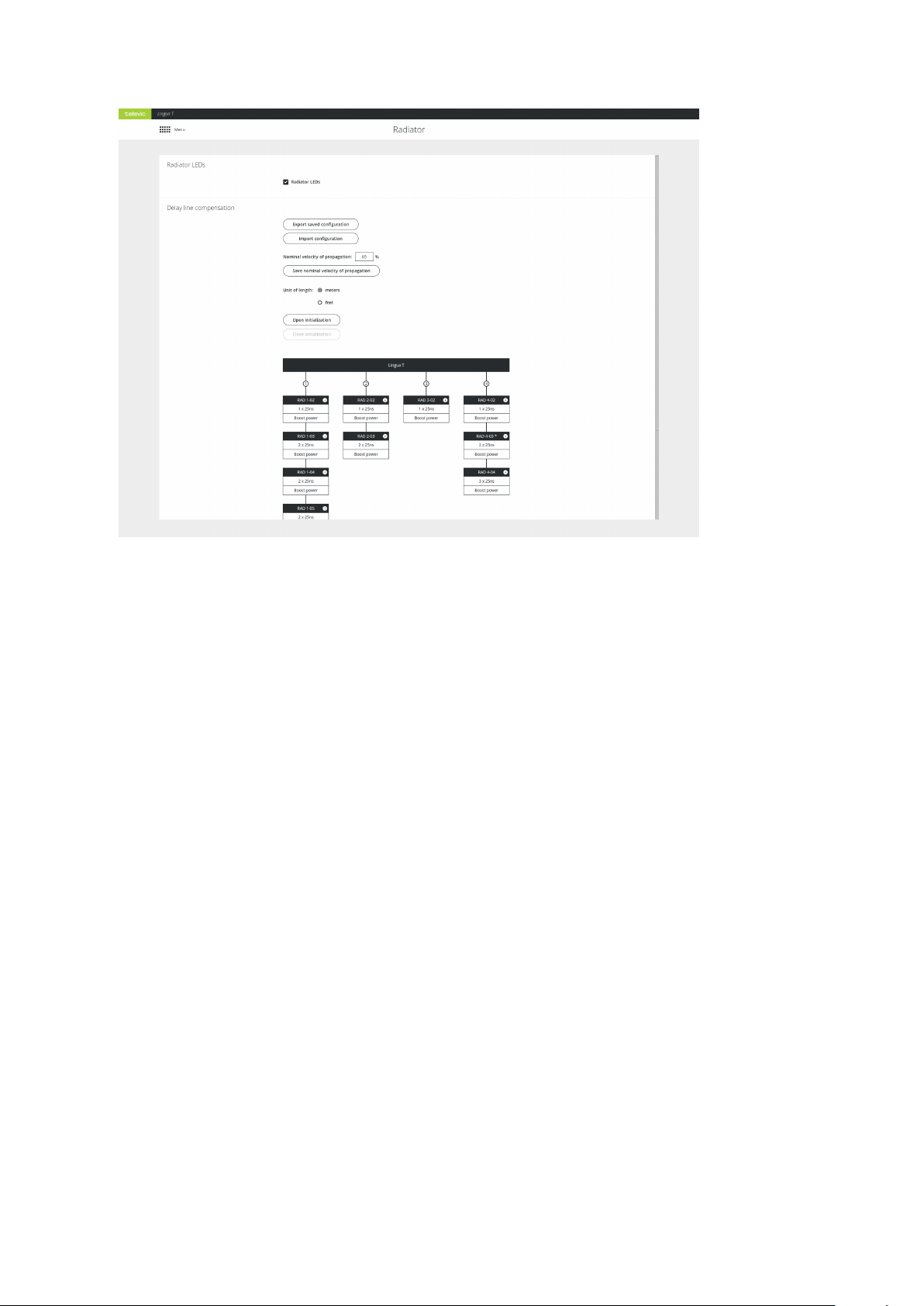
Figure 6-4 Automatic delay line compensation calibration using the Lingua IR web server
START AUTOMATIC DELAY LINE CALIBRATION
1.
Define the Nominal velocity of propagation, this is the speed at which data signals travel down
the cable expressed as a percentage of the speed of light in a vacuum. This value should be
indicated on the datasheet of the cables you are using. A typical value for this type of cable is 65%.
If no detailed value can be found it is save to use this value.
2.
Click Save nominal velocity of propagation.
3.
Click Open initialization to configure the delay line compensation.
4.
To start the calibration click Start automatic calibration. A progress icon will show that the
calibration process is ongoing. Select the check box below the port number to enable this port.
5. Once calibration is ready the web server will show a visual representation of the setup and its
transferred values. Older versions of the radiator are indicated by an asterisk (71.98.0223).
6.
Click Close initialization.
7. Test the audio reception in the room using the Lingua IR receiver and check whether there is full
coverage.
CO NF IG U R E R A DIA TO R SETTIN G S 78
Page 79
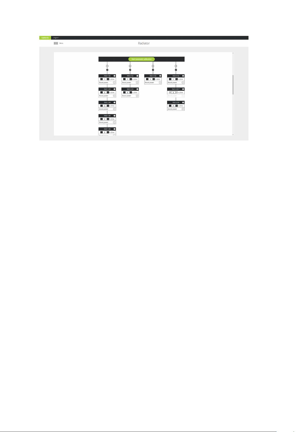
Figure 6-5 How to start automatic delay line compensation calibration using the Lingua IR web server
DELAY LINE COMPENSATION CALIBRATION RESULTS
When the calibration is ready, you get an overview of all radiators per transmitter port. Per radiator you can
adjust the delay line compensation as well as the power level. However, when you have a previous version
of the radiator (71.98.0223) it is not possible to change the power level (it is greyed out). These radiators are
indicated by an asterisk *.
Select Infrared Bands
When you use infrared, sometimes interference from other systems using the same frequency can occur. In
these cases you can disable bands.
On the Radiator page of the web server go to Disable occupied infrared bands, where you can disble
infrared bands to avoid interference from other systems that use the same infrared band such as IR wireless
microphones. Select those bands you want to disable and select Save settings.
CO NF IG U R E R A DIA TO R SETTIN G S 79
Page 80
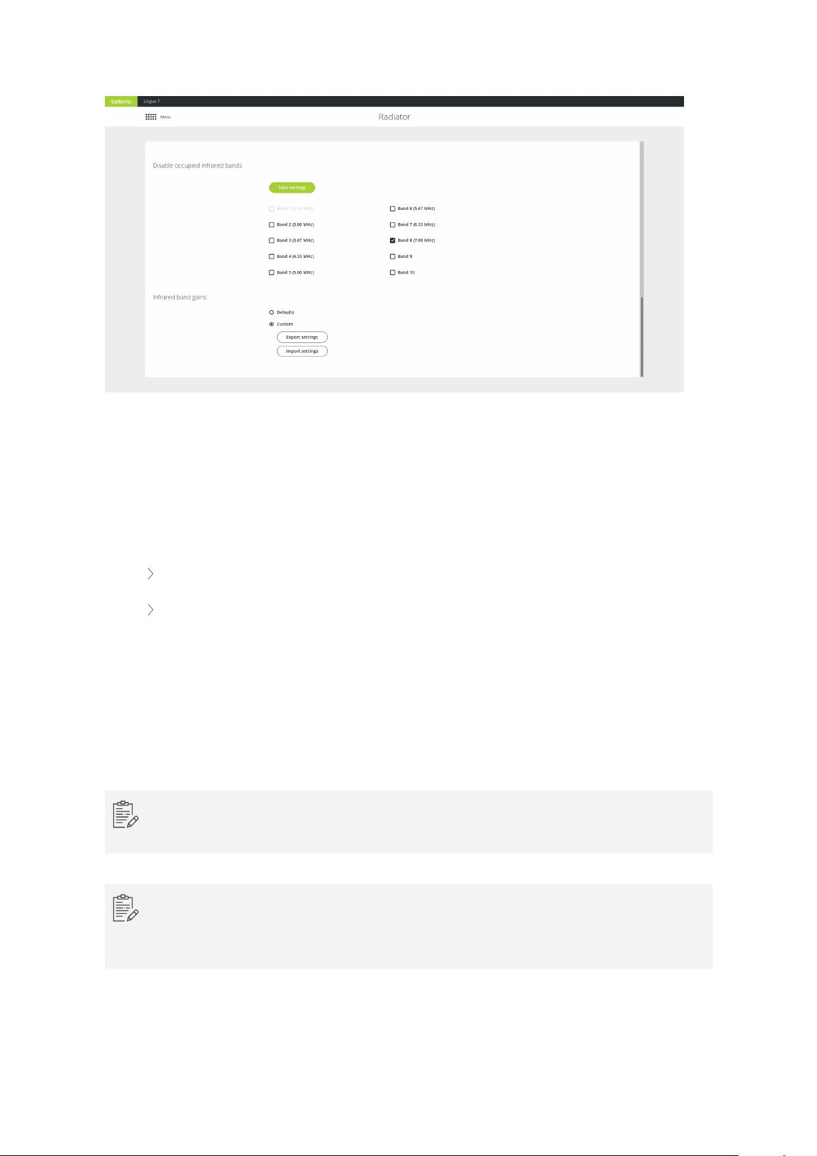
Figure 6-6 Configure infrared bands using the Lingua IR web server
Infrared Band Gains
With this setting you can configure the gain of individual infrared bands (see figure Figure 6-6 ). There are
two options available:
Default: flat gain configuration, meaning no gains are set on the radiated bands.
Custom: when you select custom and do not upload a file, the radiator uses optimized radiated
band gains. The radiator has built-in values optimized explicitly for optimal performance of an
end-to-end Televic system (compensating for frequency response characteristics). In case of
high channel counts (>12 audio channels), this will ensure that equal reception for all audio
channels.
When your system contains third-party equipment, or you want to finetune the infrared band
gains, you can upload a settings file containing the desired band gain values.
The settings file to define the custom band gain should have the extension .tir_bc. You can export
the current gain settings and use these as reference to create a custom file.
When you upload a settings file with custom values, you do not return to the Televic optimized
settings when you remove these values. To obtain these built-in settings, you need to upload a
settings file containing these Televic optimized band gain values.
CO NF IG U R E R A DIA TO R SETTIN G S 80
Page 81
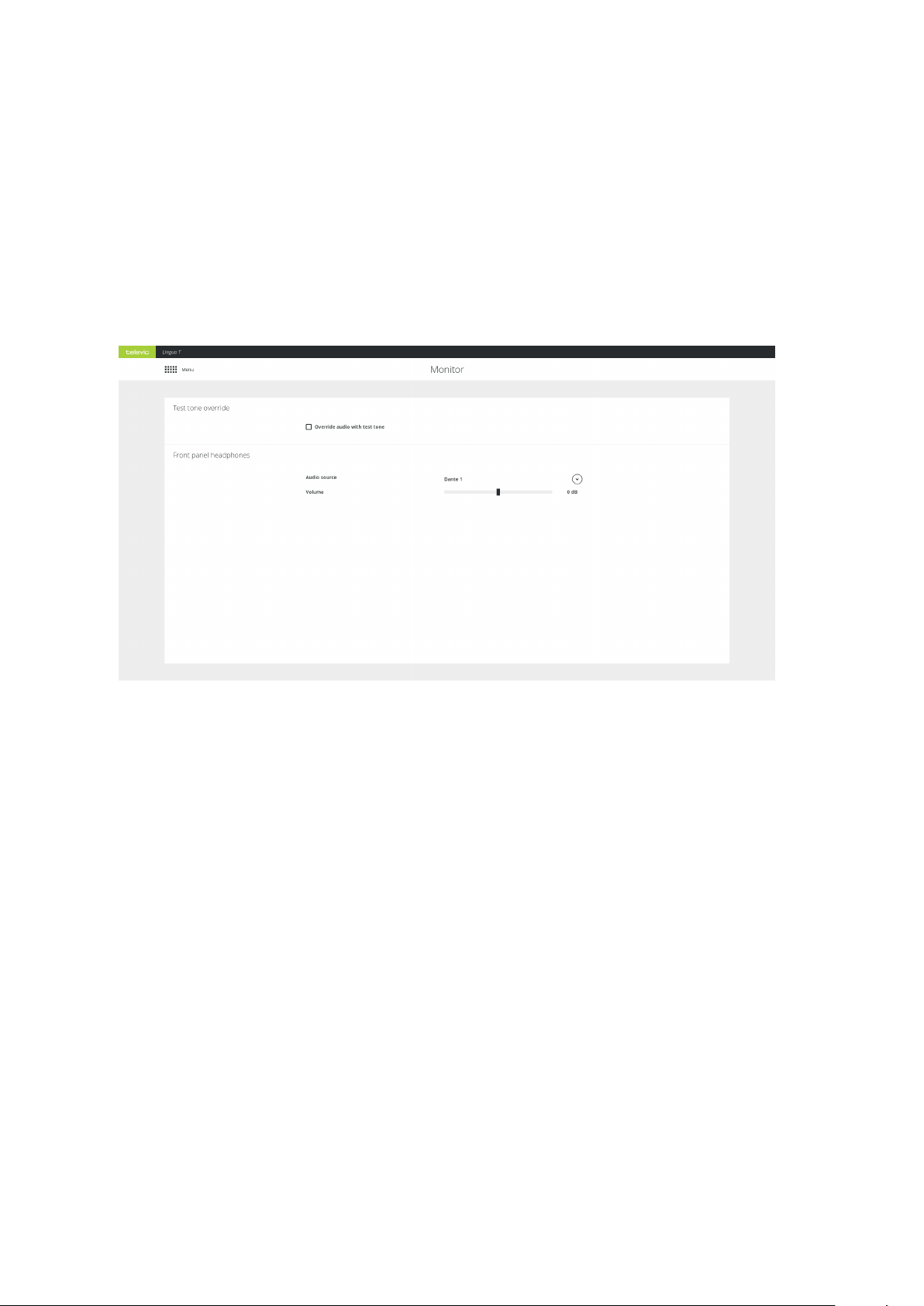
TEST THE LINGUA IR SYSTEM
Configure The Test Tone
When you set up the Lingua IR system, you need to test the audio inside the room. If during testing there is
no audio is available, you can use the test tone to check whether the receivers have audio. Select Override
audio with test tone on the Monitor page.
Figure 7-1 The Monitor page
Configure The Front Panel Headphones
On the transmitter it is possible to check the input of every Dante™ channel and the AUX input. To hear the
input plug a headphone into the front of the transmitter. On the Monitor page of the transmitter you can
select the Dante™ channel you want to listen to by opening the dropdown next to Audio source. Change
the volume of the channel by adjusting the Volume slider.
TE ST THE L ING U A IR SY ST EM 81
Page 82

Page 83
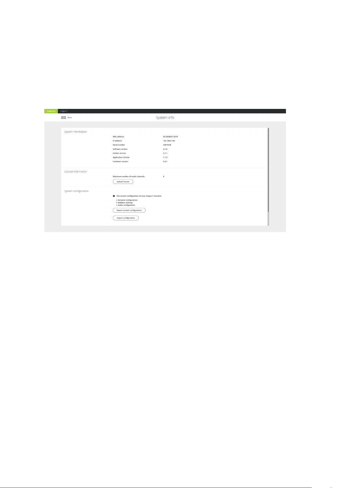
GENERAL TRANSMITTER SETTINGS
On the System info page you can find different general transmitter settings such as the MAC address, as
well as the software and hardware version of the transmitter. This is also the location where you can
manage the transmitter licenses and import and export the configurations of all settings of the transmitter.
Figure 8-1 The System info page
View System Information
Under System information you can find all transmitter specifications such as the MAC address, the IP
address and the serial number of the transmitter. Next to this information you can also see which versions
are running on the transmitter.
Manage Transmitter Licenses
There are two different licenses available for the Lingua IR transmitter, which license you need depends on
the amount of channels you require. There is a license for six, twelve or forty channels. You can upgrade the
license whenever you require additional channels. Follow the procedure described below to acquire a new
license. Once you have received the license, click Upload license on the System info page.
HOW OBTAIN A NEW LICENSE
When you want to upgrade your license perform the following procedure:
GEN ERA L TR ANSMITTER SET TINGS 83
Page 84
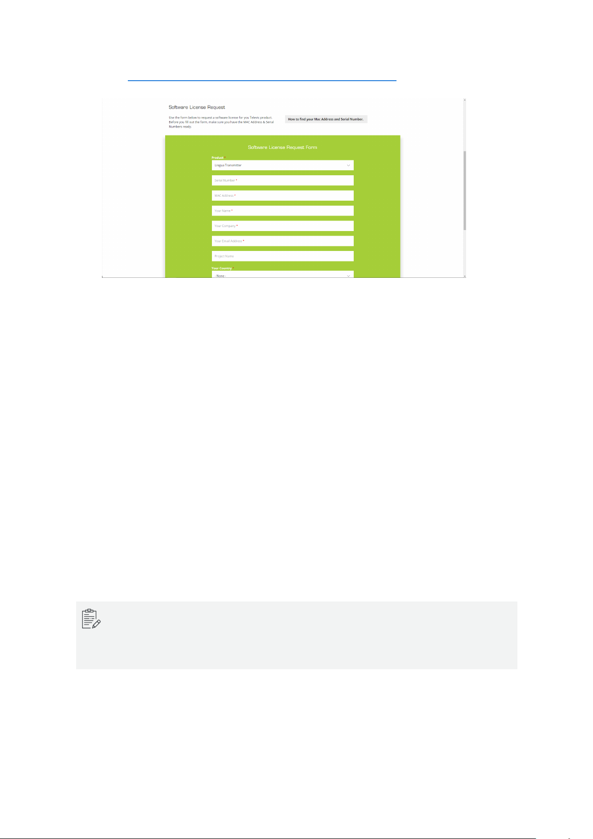
1. Go to https://www.televic-conference.com/en/software-license-request , the website describes
where you can find all relevant information needed to request a license.
2. Fill in the request form with the product details and your contact information.
3.
Click Submit.
4. You will receive an email with the license file on the email address specified in the form.
Manage System Configurations
When you have similar rooms with similar setups you can export the complete configuration of one room
and upload it to the infrared system of the other room. The system configuration file contains the network
settings, the radiator settings and the audio settings.
Click Export current configuration to export the configuration. To upload the configuration click Import
configuration.
View System Logging
When you have some technical problems with your system it can help to view the logging of the system. To
download the log files click Download under Download log archive on the System info page.
It may take some time to download the log files because the system first needs to retrieve all data
and then compress them to a TAR file.
The most recent log file is it the one with the number 00.
GEN ERA L TR ANSMITTER SET TINGS 84
Page 85
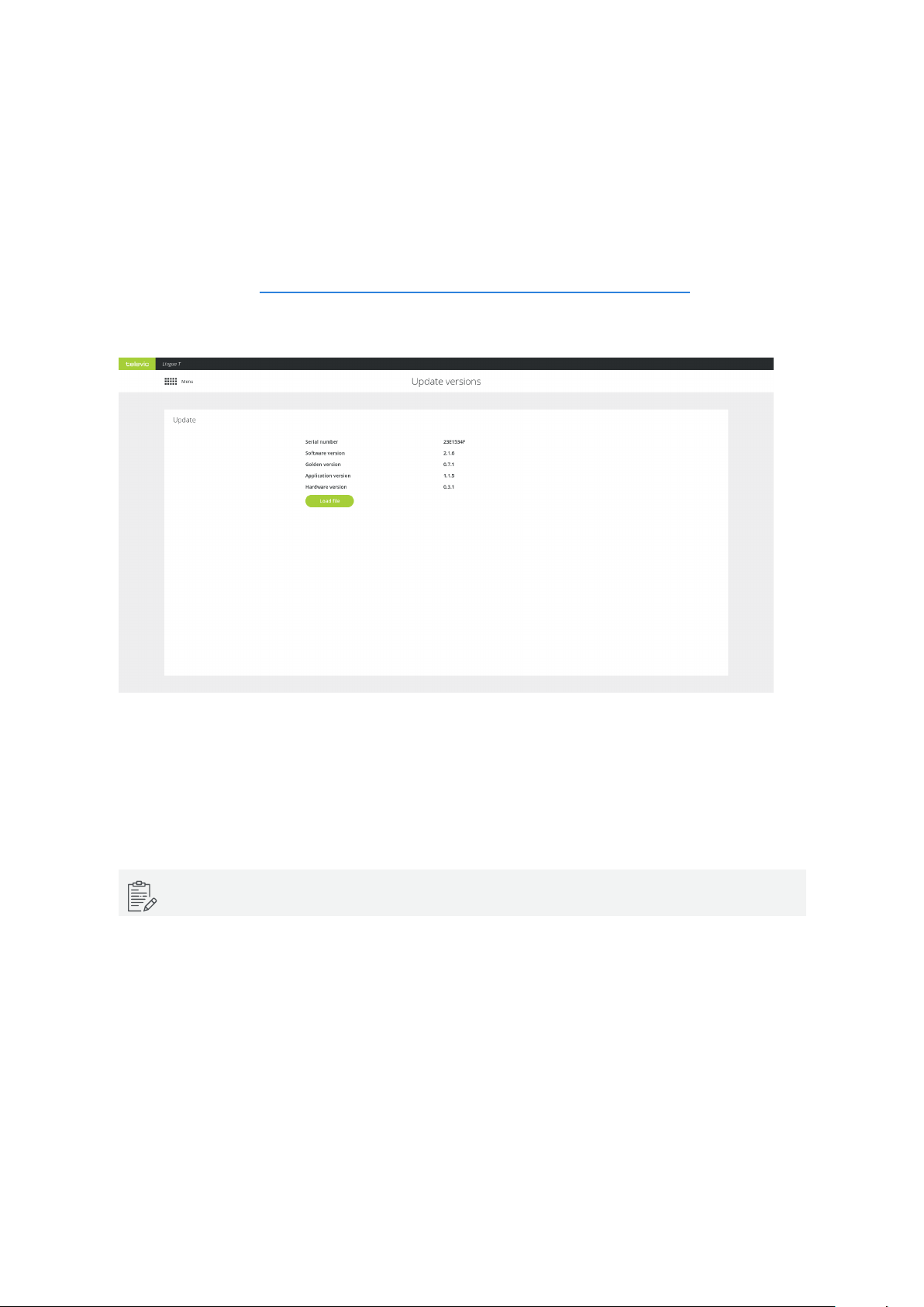
UPDATE THE LINGUA IR TRANSMITTER AND RADIATOR
When there is a new version available for the transmitter or radiator, you can download it from the Televic
Conference website ( https://www.televic-conference.com/en/lingua-ir-software-updates). Then click Load
file on the Update page and select the file, then click Start update. During update you can monitor the
progress on the page.
Figure 9-1 The Update page
On the update page you can find all versions related to the transmitter. The software version is the version
for the web server, the fallback version is the firmware fallback version and the application version is the
firmware version of the transmitter.
Perform a power cycle after the update to complete the update process.
UP DAT E T HE L ING U A I R T RAN SMITTER AND R A DIATO R 85
Page 86

Page 87
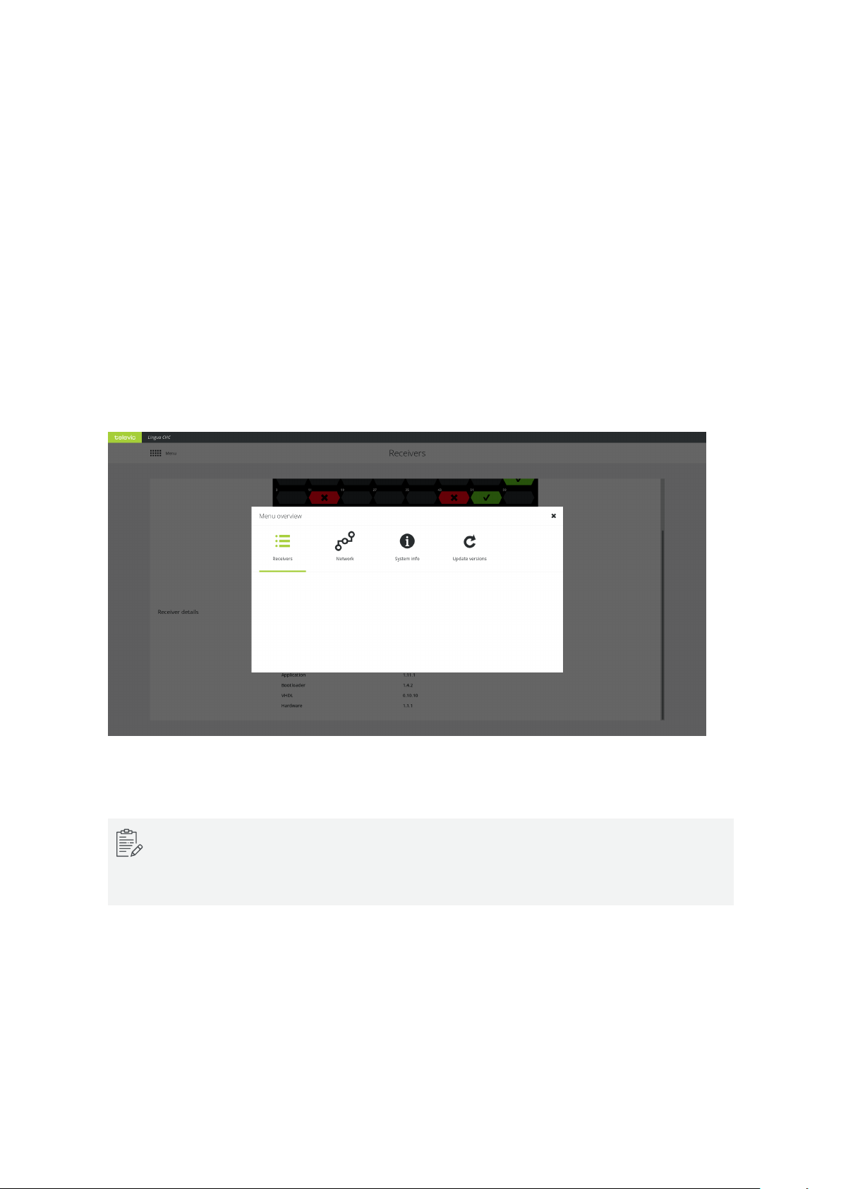
CONFIGURE THE CHARGING CASE SETTINGS
Introduction
Lingua IR has an intuitive web server that allows you to configure and monitor different charging cases and
receiver settings. With the web server you can configure the network settings, update the charging case
and the receivers and monitor the receivers. You can easily navigate to the different pages using the main
menu.
The default IP address of the transmitter web server is 192.168.0.150. To be able to access the web server,
configure your network settings as described in "Configure IP settings" on page63.
Figure 10-1 The main menu of the Lingua IR charging case web server
When you have more than one charging case, they will all have the same IP address by default.
You need the change the IP address of all charging cases individually to be able to access them at
the same time.
CO NF IG U R E T HE C HAR G ING CA SE SETTING S 87
Page 88

Page 89
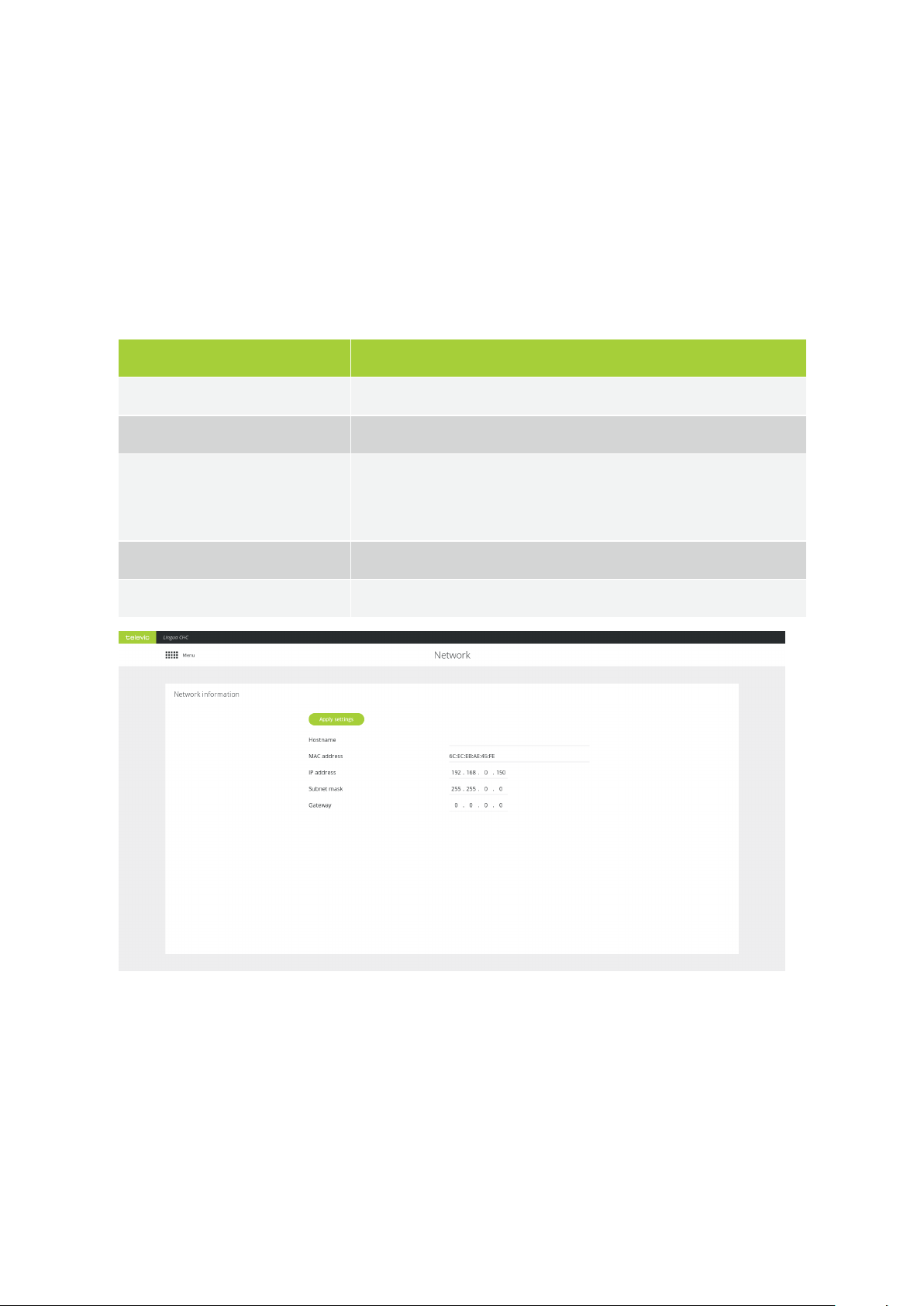
CONFIGURE CHARGING CASE NETWORK SETTINGS
Network Information
On the Network page you can configure the following parameters:
Parameter Description
Hostname The name you want to give to the Lingua IR system
MAC address The MAC address of the charging case
IP address The IP address to access the transmitter, the default value is
192.168.0.150
the page automatically reloads using the new IP address.
Subnet mask Default subnet is 255.255.255.0
Gateway The access point to another network.
. When you change the IP address of the charging case,
Figure 11-1 The Network page
CO NF IG U R E C H ARG I NG C ASE N ET WORK SET TI NGS 89
Page 90

Page 91
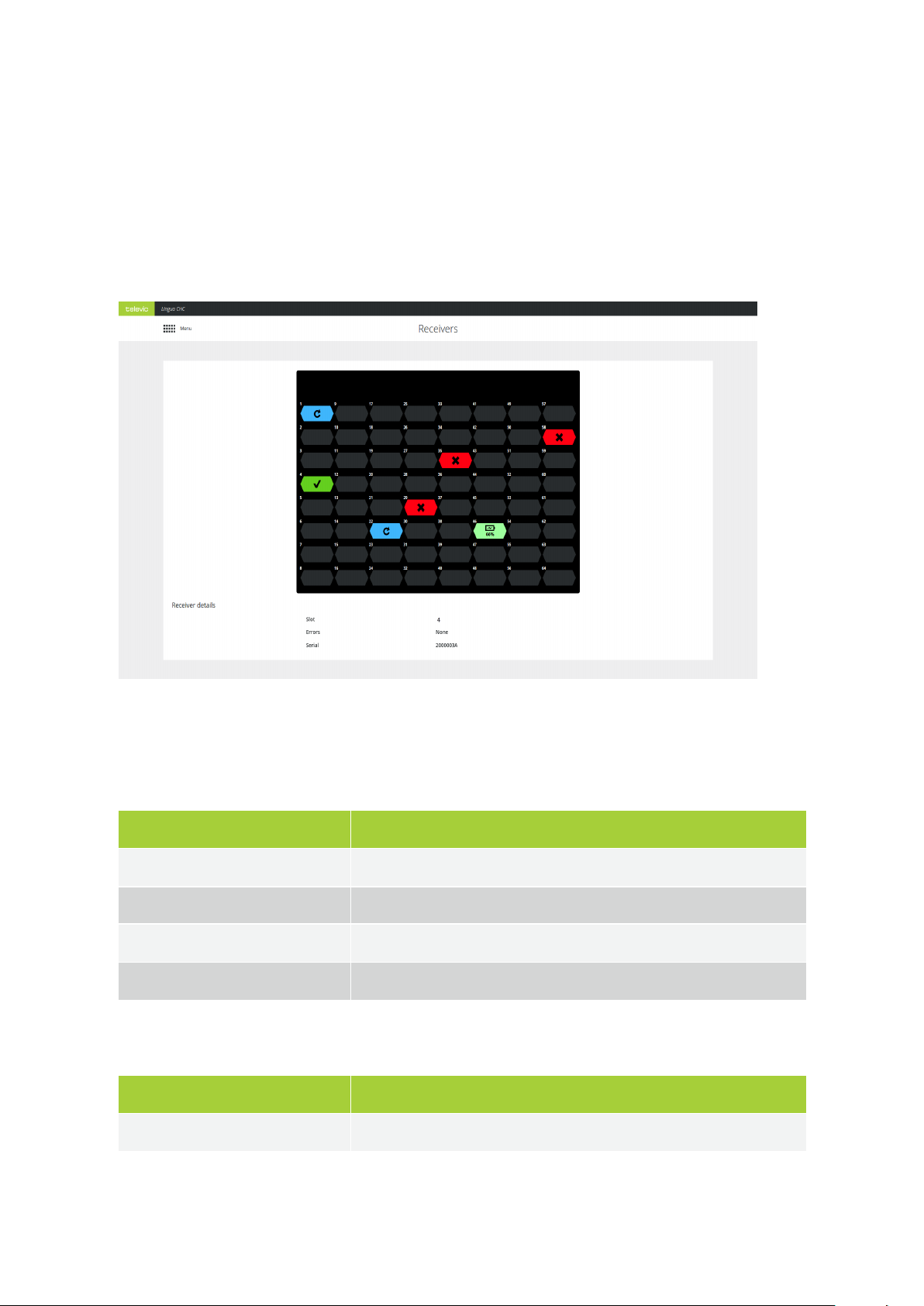
CONFIGURE THE LINGUA IR RECEIVERS
Monitor Receivers
Figure 12-1 The Receiver page of the web server
On the Receiver page you get an overview of the receivers in the charging case. Here you can see on which
positions receivers are charging. Different colors indicate different states of the receivers:
Color Meaning
Green Receiver fully charged and no errors
Light green The receiver is updating
Red Error with receiver. Depending on the error different actions are possible.
Blue The receiver is updating
Below the table you can find additional receiver information when you click on a receiver in the overview
image.
Parameter Description
Slot The position in the charging case were the receiver is located
CO NF IG U R E T HE L ING U A I R R ECE IV ERS 91
Page 92
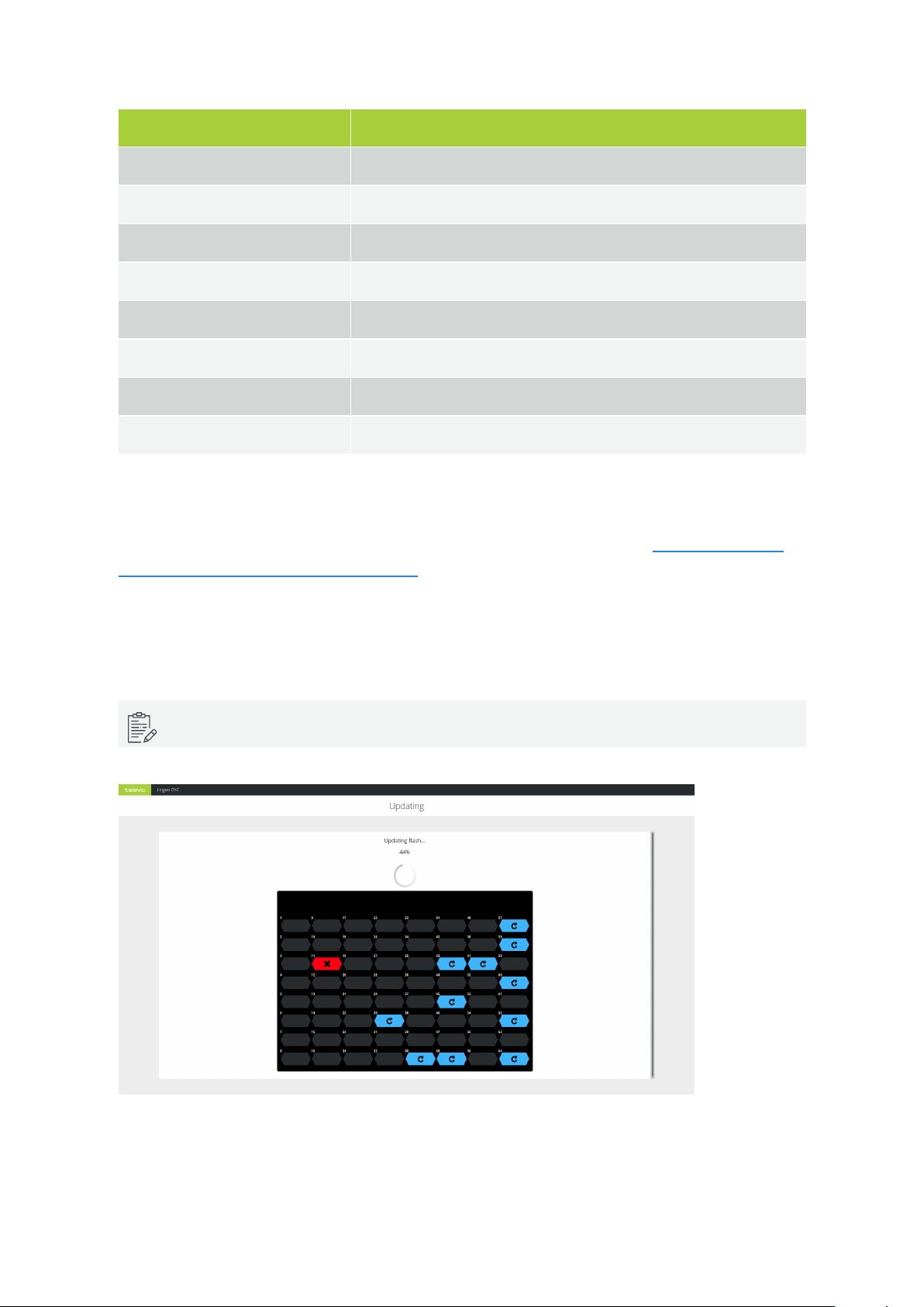
Parameter Description
Errors Errors on the receiver
Serial Serial number of the receiver
Battery charge Battery percentage of the receiver
Maximum channels Amount of licensed channels on the receiver
Application Firmware version
Bootloader Bootloader version
VHDL VHDL version
Hardware Hardware version
Update Receivers
To update the receivers download the tuf file from the Televic Conference website (https://www.televic-
conference.com/en/lingua-ir-software-updates). Open the file and start the upload on the Update page.
When the upload is complete, you can start the update process.
On the receiver page you can see the progress of the update process. Updating receivers are indicated in
blue. When the receiver update is done click Finish update.
When there is a communication error on the receiver then that receiver will not update.
Figure 12-2 The charging case view when the receivers are updating
CO NF IG U R E T HE L ING U A I R R ECE IV ERS 92
Page 93
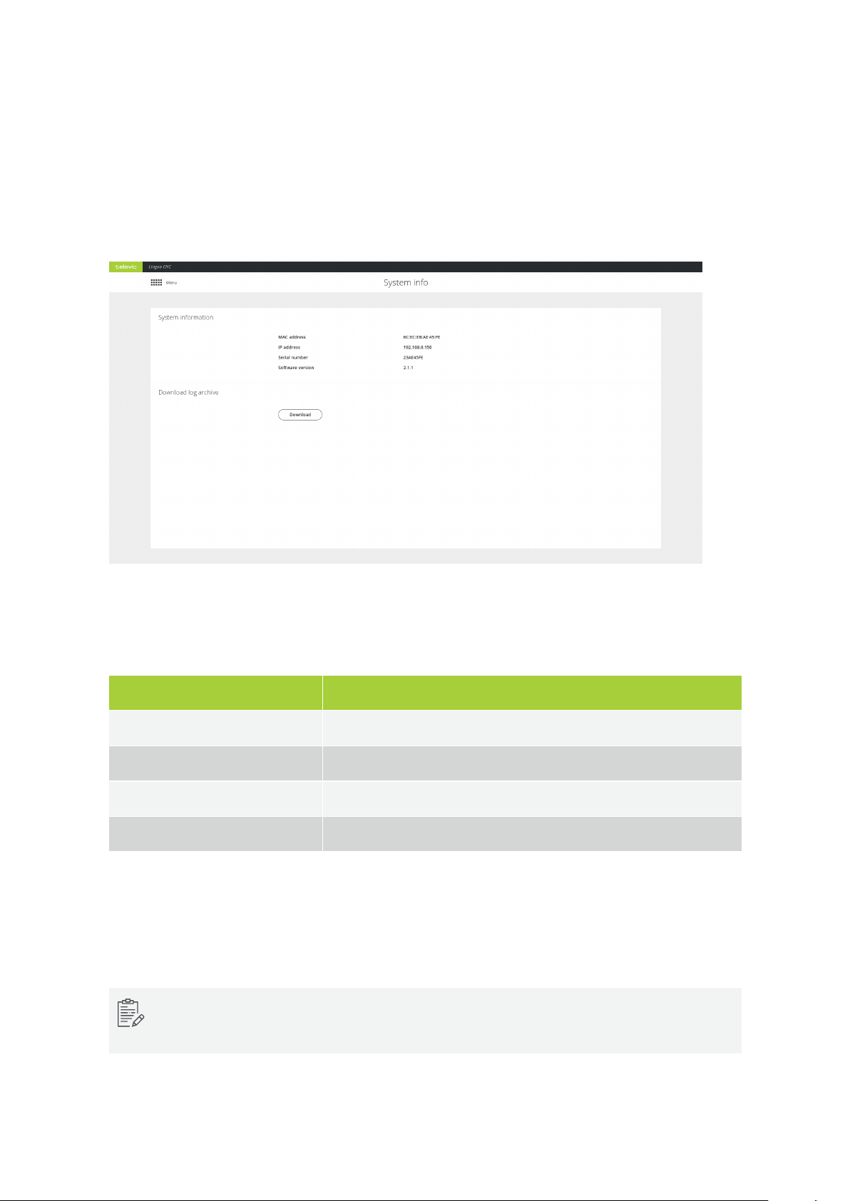
CHARGING CASE SYSTEM INFORMATION
The system info page shows the following information:
Figure 13-1 The System info page of the web server
SYSTEM INFORMATION
Parameter Description
MAC address The MAC address of the charging case
IP address The IP address of the charging case (192.168.150) is the default address)
Serial number The serial number of the charging case
Software version The version of the web server
DOWNLOAD LOG ARCHIVE
For troubleshooting purposes it is interesting to have the log files containing all events. Click Download for
all these log files.
It may take some time to download the log files because the system first needs to retrieve all data
and then compress them to a TAR file. The latest log files it the one with the number 00.
CH A RGIN G CASE S Y STEM INF O R MA TIO N 93
Page 94

Page 95
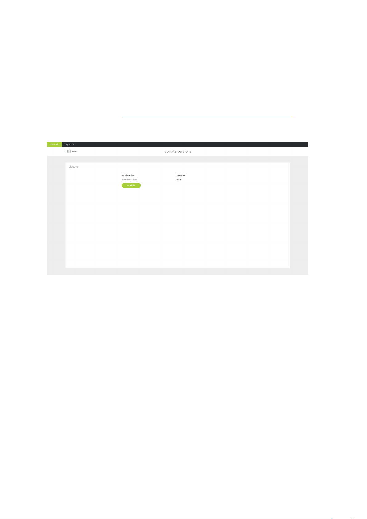
UPDATE THE CHARGING CASE AND RECEIVER
When there is a new version available for the charging case or receivers, you can download these from the
Televic Conference website ( https://www.televic-conference.com/en/lingua-ir-software-updates). Then
click Load file on the Update page and select the file, then click Start update. During update you can
monitor the progress on the Update page.
Figure 14-1 The Update page
On the update page you can find all versions related to the charging case. The software version is the
version for the web server.
UP DAT E T HE C HAR G ING CA SE A ND R ECE IV ER 95
Page 96

TE LE VIC CONF E R E N CE
www.bramshawics.com
t: 1800 507 557
from
BRAMSHAW ICS
Conference Communications
Leo Bekaertlaan 1
8870 Izegem
Belgium
+32 51 30 30 45
GET IN TOUCH
 Loading...